EP2581879A2 - Three-frame difference moving target acquisition system and method for target track identification - Google Patents
Three-frame difference moving target acquisition system and method for target track identification Download PDFInfo
- Publication number
- EP2581879A2 EP2581879A2 EP12161420.0A EP12161420A EP2581879A2 EP 2581879 A2 EP2581879 A2 EP 2581879A2 EP 12161420 A EP12161420 A EP 12161420A EP 2581879 A2 EP2581879 A2 EP 2581879A2
- Authority
- EP
- European Patent Office
- Prior art keywords
- image
- frame
- generate
- warped
- target
- Prior art date
- Legal status (The legal status is an assumption and is not a legal conclusion. Google has not performed a legal analysis and makes no representation as to the accuracy of the status listed.)
- Granted
Links
Images



Classifications
-
- G—PHYSICS
- G06—COMPUTING OR CALCULATING; COUNTING
- G06T—IMAGE DATA PROCESSING OR GENERATION, IN GENERAL
- G06T7/00—Image analysis
- G06T7/20—Analysis of motion
- G06T7/254—Analysis of motion involving subtraction of images
-
- G—PHYSICS
- G06—COMPUTING OR CALCULATING; COUNTING
- G06T—IMAGE DATA PROCESSING OR GENERATION, IN GENERAL
- G06T2207/00—Indexing scheme for image analysis or image enhancement
- G06T2207/10—Image acquisition modality
- G06T2207/10016—Video; Image sequence
-
- G—PHYSICS
- G06—COMPUTING OR CALCULATING; COUNTING
- G06T—IMAGE DATA PROCESSING OR GENERATION, IN GENERAL
- G06T2207/00—Indexing scheme for image analysis or image enhancement
- G06T2207/10—Image acquisition modality
- G06T2207/10032—Satellite or aerial image; Remote sensing
-
- G—PHYSICS
- G06—COMPUTING OR CALCULATING; COUNTING
- G06T—IMAGE DATA PROCESSING OR GENERATION, IN GENERAL
- G06T2207/00—Indexing scheme for image analysis or image enhancement
- G06T2207/30—Subject of image; Context of image processing
- G06T2207/30212—Military
Definitions
- Embodiments pertain to systems and methods for acquiring and tracking moving targets. Some embodiments pertain to video tracking systems. Some embodiments pertain to target trackers for identifying a target track of a moving target. Some embodiments pertain to imaging systems.
- Video tracking systems may be used to locate a moving object over time using a camera or other imaging device. These systems have a variety of uses that include human-computer interaction, security and surveillance, video communication and compression, augmented reality, traffic control, medical imaging and video editing. Video tracking can be processing intensive due to the amount of data that is contained in video. Adding further to the complexity of video tracking is the possible need to use object recognition techniques for tracking.
- a target-tracking system and method for acquiring a moving target and determining an initial target track suitable for use in a high-clutter environment are generally described herein.
- the system may register image information of first and second warped images with image information of a reference image. Pixels of the warped images may be offset based on the outputs of the registration to align the warped images with the reference image.
- a three-frame difference calculation may be performed on the offset images and the reference image to generate a three-frame difference output image.
- Clutter suppression may be performed on the three-frame difference image to generate a clutter-suppressed output image for use in moving target acquisition.
- the clutter suppression may include performing a gradient operation on a background image and dividing the three-frame difference output image by the gradient to remove residuals.
- FIG. 1 illustrates an operational environment of a target-tracking system in accordance with some embodiments
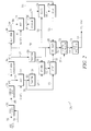
- FIG. 2 is a block diagram of a three-frame difference moving target-tracking system in accordance with some embodiments
- FIG. 3 illustrates an example three-frame difference calculation in accordance with some embodiments
- FIG. 4 is a sketch of a reference image in accordance with some embodiments.
- FIG. 5 is a sketch of a three-frame difference output image in accordance with some embodiments.
- FIG. 6 is a sketch of a clutter-suppressed output image in accordance with some embodiments.
- FIG. 7 is a procedure for target track identification in accordance with some embodiments.
- FIG. 1 illustrates an operational environment of a target-tracking system in accordance with some embodiments.
- Operational environment 100 includes a moving platform 110, which may include a target-tracking system 102 and imager 104 configured for tracking a moving target 106 and identifying a target track 107.
- the target-tracking system 102 may be suitable for identifying and tracking the moving target 106 in an environment with high-clutter 108.
- the imager 104 may provide video frames to the target-tracking system 102.
- the target-tracking system 102 may be configured to process the video frames and generate a clutter-suppressed output image for subsequent image processing for use in moving target acquisition and target tracking.
- the target-tracking system 102 may be configured to register image information of first and second warped images with image information of a reference image, and offset pixels of the warped images based on the outputs of the registration to align the warped images with the reference image.
- the target-tracking system 102 may perform a three-frame difference calculation on both the offset images and the reference image to generate a three-frame difference output image.
- Clutter suppression may be performed on the three-frame difference image to generate the clutter-suppressed output image for use in moving target acquisition and target tracking.
- the target-tracking system 102 may also be used to identify a target track 107.
- the use of three frames may be sufficient to segment a moving target without the need to perform a background estimate.
- the three-frame difference calculation may locate and remove any misregistration and any parallax induced clutter.
- the target-tracking system 102 may be suitable for use on a moving platform 110, although this is not a requirement as the target-tracking system 102 is equally suitable for use on a non-moving platform.
- the moving platform 110 may be an aerial sensor such as aircraft including an unmanned aerial vehicle (UAV), although the scope of the embodiments is not limited in this respect.
- UAV unmanned aerial vehicle
- the target-tracking system 102 may also be suitable for use on wide-area sensors.
- FIG. 2 is a block diagram of a three-frame difference moving target-tracking system in accordance with some embodiments.
- Three-frame difference moving target-tracking system 200 may be suitable for use as target-tracking system 102 ( FIG. 1 ), although other configurations may also be suitable.
- the three-frame difference moving target-tracking system 200 may be configured to receive frames of a video stream 201 from an imager, such as imager 104 ( FIG. 1 ), receive navigation data 211 and 261 and frame-timing and target information 241 from the imager 104 and from a platform, such as moving platform 110 ( FIG. 1 ).
- the target-tracking system 200 may be configured to generate a clutter-suppressed output image 233 which may be subsequently processed to identify a target track and to track a target, such as target 106 ( FIG. 1 ).
- the three-frame difference moving target-tracking system 200 may include a frame-selection element 202 to select frames from the video stream 201, a condition element 204 to condition the selected frames 203 and delay elements 206 and 208 to delay the selected frames 203.
- the target-tracking system 200 may also include warping elements 210 and 212 to generate first and second warped images 213 and 215, respectively, and transform elements 216, 218 and 220 to operate and the selected frames 203 as described below.
- the three-frame difference moving target-tracking system 200 may also include a first registration element 222 to align image information 217 of a first warped image 213 with image information 219 of a reference frame 207 and a second registration element 224 to align image information 221 of a second warped image 215 with the image information 219 of the reference frame 207.
- Image information 217 may be generated by transform element 216 and image information 221 may be generated by transform element 220.
- the target-tracking system 200 may also include a first offset element 226 to offset pixels of the first warped image 213 based on the output 223 of the first registration element 222 to align the pixels with corresponding pixels of the reference frame 207 to generate a first offset image 227.
- the target-tracking system 200 may also include a second offset element 228 to offset the pixels of the second warped image 215 based on the output 225 of the second registration 224 to align the pixels with corresponding pixels of the reference frame 207 to generate a second offset image 229.
- the three-frame difference moving target-tracking system 200 may also include a three-frame difference calculation element 230 to perform a pixel-by-pixel three-frame difference calculation (see FIG. 3 ) on the first offset image 227, the second offset image 229 and the reference frame 207 (see FIG. 4 ) to generate a three-frame difference output image 231 (see FIG. 5 ).
- the three-frame difference moving target-tracking system 200 may also include a clutter suppression element 232 to perform clutter suppression on the three-frame difference image 231 to generate the clutter-suppressed output image 233 (see FIG. 6 ) for use in identification of the target track 107.
- the three-frame difference moving target-tracking system 200 may also include an image-processing element 234.
- the image-processing element 234 may be configured to perform image processing on the clutter-suppressed output image 233.
- a target-track output 235 may be provided by image-processing element 234.
- FIG. 3 illustrates an example three-frame difference calculation in accordance with some embodiments.
- the three-frame difference calculation may comprise generating each pixel of the three-frame difference output image 231 based on the following equation: abs ⁇ D C - D B - abs D A / 2 * sign D C .
- D A is a difference between corresponding pixels in the reference frame 207 and the second offset image 229
- D B is a difference between corresponding pixels in the reference frame 207 and the first offset image 227
- D C is a difference between corresponding pixels in the first offset image 227 and the second offset image 229.
- the above equation may be calculated for each pixel of the image. In these embodiments, the above equation may be used to recover moving objects at time T.
- a moving object is illustrated at three different times, time M T-2n , time M T-n and time M T .
- D A M T-n -M T-2n
- D B M T-n -M T
- D C M T -M T-2n .
- Deflections in lines 302, 304 and 306 illustrated in FIG. 3 correspond to a location of a moving target in a row of pixels of the image.
- Deflections in lines 308, 310 and 312 illustrate the differences D A , D B and D C .
- Deflections in lines 314, 316 and 318 illustrate the portions of the above equation shown on the left, which are used to compute the three-frame difference output image 231 on a pixel-by-pixel basis.
- the frame arithmetic to recover moving objects at time T -n may be based on the following equation:
- the frame arithmetic to recover the moving objects at time T -2n may be based on the following equation:
- This pixel-by-pixel three-frame difference calculation performed by the three-frame difference calculation element 230 may be performed on the first offset image 227, the second offset image 229 and the reference frame 207 to generate the three-frame difference output image 231.
- FIG. 4 is a sketch of a reference frame 207 in accordance with some embodiments.
- Reference frame 207 includes moving target 106 in an environment shown with high clutter 108.
- the target-tracking system 102 may be configured to acquire the moving target 106 and identify a target track based on frames of the reference frame 207 as described herein.
- Reference frame 207 may be provided by delay element 206 ( FIG. 2 ).
- FIG. 5 is a sketch of a three-frame difference output image 231 in accordance with some embodiments.
- Three-frame difference output image 231 shows the moving target 106 of the reference frame 207 ( FIG. 4 ). Although most of the clutter and background have been removed, gradient objects 502 within the background 504 may remain. Gradient objects 502 are the residual that results from registration errors and parallax-induced misalignment. Gradient objects 502 may be considered ⁇ clutter leakage'.
- Three-frame difference output image 231 may be generated by the three-frame difference calculation element 230 ( FIG. 2 ).
- the clutter suppression element 232 ( FIG. 2 ) may be configured to perform clutter suppression on the three-frame difference image 231 to generate the clutter-suppressed output image 233 for subsequent use in target tracking and identification of the target track 107.
- FIG. 6 is a sketch of a clutter-suppressed output image 233 in accordance with some embodiments.
- the clutter-suppressed output image 233 shows the moving target 106 of the three-frame difference output image 231 ( FIG. 5 ) however the gradient objects 502 ( FIG. 5 ) have been removed from the background 604.
- the clutter suppression element 232 may be configured to calculate the image background 504 ( FIG. 5 ) of the three-frame difference output image 231 ( FIG. 5 ) by subtracting, on a pixel-by-pixel basis, the three-frame difference output image 231 from the reference frame 207 to remove moving objects and generate a background image.
- the background image would correspond to image 231 without moving objects (e.g., the moving target 106).
- the clutter suppression element 232 may perform a gradient operation on this background image to calculate a gradient of the background image and may divide the three-frame difference output image 231 by the gradient to generate the clutter-suppressed output image 233 shown in FIG. 6 .
- the gradient operator may identify any gradient objects 502 that may result from translation error in the warping and registration processes.
- the clutter-suppressed output image 233 shown in FIG. 6 has gradient objects removed from the background 604 leaving only the moving target 106. Any other moving objects in the reference frame 207 ( FIG. 4 ) may also remain.
- the image-processing element 234 may be configured to perform image processing on the clutter-suppressed output image 233 to segment the pixels of the background 604 from non-background pixels to detect the moving target 106 in the image 233.
- the target track 107 ( FIG. 1 ) as well as determine an initial target location may also be determined.
- a target-track output 235 ( FIG. 2 ) may be provided by image-processing element 234.
- the delay elements 206 and 208 may each be configured to delay a first frame by a predetermined frame delay time (T).
- the first frame may be a first frame of the selected group of frames 203 and may be considered a twice-delayed frame 209 (having a delay of 2T).
- Delay element 206 may be configured to delay a second frame by the predetermined frame delay time T.
- the second frame may also be selected from the selected group of frames 203 and may be used as the reference frame 207.
- the warp element 212 may be configured to warp, based on the navigation data 211, a third frame 205 of the selected group of frames 203 to generate the first warped image 213.
- the third frame 205 may have no delay with respect to the twice-delayed frame 209 and the reference frame 207.
- Warp element 214 may be configured to warp, based on the navigation data 261, the twice-delayed frame 209 to generate the second warped image 215.
- the frame delay time (T) may range from as little as the time of one frame to up to several seconds, depending on the navigation data and the frame timing and target information.
- the frame delay time may be determined based on the speed and size of the target 106. For fast moving targets, shorter frame delay times may be used. Longer frame delays may be determined by the length of time the moving object takes to vacate the region it occupied during the previous selected frame (i.e., to get out of its own way). In other words, the frame delay time may be selected so that the target 106 does not overlap with itself in adjacent selected frames. In an example, embodiment, for a small car travelling at 2.5 miles per hour, the frame delay time may be roughly 2.5 seconds.
- warping the third frame 205 may align non-moving objects in the image of frame 205 so that they occupy the same positions as they do in the reference frame 207.
- warping the twice-delayed frame 209 may align the non-moving objects in the image of frame 209 so that they occupy the same positions as they do in the reference frame 207.
- the twice-delayed frame 209 may delayed by T-2n with respect to the third frame 205 and the reference frame 207 may be delayed by T-n with respect to the third frame 205.
- the use of the navigation data 211 and 261 allows the images of frames 205 and 209 to be aligned with the reference frame.
- the navigation data 211, 261 comprises first and second navigation data streams that include position information of the imager 104 ( FIG. 1 ), directional information of the imager 104 (i.e., a direction the imager 104 is pointed), and velocity information of the imager 104 (i.e., when the imager 104 is moving).
- the navigation data 211, 261 may take into account the movement of the moving platform 110 ( FIG. 1 ).
- the navigation data 211, 261 may describe the position and altitude of the platform 110, which may correspond to the position of the imager 104.
- the navigation data 211, 261 may also describe where the imager 104 is pointed in embodiments in which the imager 104 is configured to swivel.
- the navigation data 211, 261 may also describe additional imager-related information for use by warp elements 212 and 214 to calculate an image-warp so that will get the images of frames 205 and 209 will overlay with the reference frame 207.
- the additional imager-related information may include specs that may change in real time, such as focal length (e.g., zoom), the wavelengths that the imager 104 is recording (B&W, color or infrared (IR)), etc.
- the warping elements 212 and 214 may perform dynamic and real-time image warping.
- a one-to-one correspondence between the navigation data 211, 261 and the frames 205, 209 may be provided, while in other embodiments, the navigation data 211, 261 and the frames 205, 209 may be recorded at different rates.
- the navigation data 211, 261 may be interpolated to correspond to the time when a corresponding frame was captured.
- the navigation data may be fixed and navigation data 211 may be the same as navigation data 261.
- the transform element 216 may be configured to perform a transform on the first warped image 213 to generate spatial frequency domain image information 217 of the first warped image 213.
- Transform element 220 may be configured to perform a transform 220 on the second warped image 215 to generate spatial frequency domain image information 221 of the second warped image 215.
- Transform element 218 may be configured to perform a transform on the reference frame 207 to generate spatial frequency domain image information 219 of the reference frame 207.
- the transform elements 216, 218 and 220 may be configured to perform discrete Fourier transforms such as fast-Fourier transforms (FFTs).
- FFTs discrete Fourier transforms
- performing an FFT on the first warped image 213 may generate the spatial frequency domain image information 217 of the first warped image 213
- performing an FFT on the second warped image 215 may generate the spatial frequency domain image information 221 of the second warped image 215,
- performing an FFT on the reference image (of reference frame 207) may generate the spatial frequency domain image information 219 of the reference frame 207.
- the FFTs are performed concurrently on the three images 213, 207 and 215 (i.e., in parallel).
- the first registration element 222 may perform a first correlation to correlate the spatial frequency domain image information 217 of the first warped image 213 with the spatial frequency domain image information 219 of the reference frame 207.
- the second registration element 224 may perform a second correlation to correlate the spatial frequency domain image information 221 of the second warped image 215 with the spatial frequency domain image information 219 of the reference frame 207.
- the pixels of the first warped image 213 may be offset by offset element 226 based on the output 223 of the first correlation to align the pixels with corresponding pixels of the reference frame 207 to generate the first offset image 227.
- Pixels of the second warped image 215 may be offset by offset element 228 based on the output 225 of the second correlation to align the pixels with corresponding pixels of the reference frame 207 to generate the second offset image 229.
- the correlations may help correct for errors in the navigation data and may remove translation error.
- the three-frame difference moving target-tracking system 200 may be configured to delay, warp, transform, register, offset, perform the three-frame difference calculation and perform clutter suppression for a next set of three frames for further use in target tracking and target track identification. In some of these embodiments, these operations are repeated in such a way that the reference frame 207 from a prior operation now becomes the twice-delayed frame 209 of a next set of operations, and the third frame 205 becomes the reference frame 207.
- frame-selection element 202 may be configured to select frames 202 from the video stream 201 based on the frame timing and target information 241.
- the frame timing and target information 241 may include a length of the moving target 106, a minimum velocity of the target 106, and frame-timing information of frames of the video stream 201.
- the frame-selection element 202 may select every frame of the video stream.
- every n th frame of the video stream 201 may be selected in which n may range from two to up to one-hundred or more.
- every third frame may be selected in some embodiments, while in other embodiments, every tenth or hundredth frame of the video stream 201 may be selected depending on the size or length of the target 106, the velocity of the target 106 and the frame timing.
- the selected frames 203 may be conditioned by the frame condition element 204 to remove or reduce noise, correct for corrupted pixels and correct for brightness, among other things.
- a ground sample distance may also be used to determine the amount of ground that each pixel represents for use in determining how often frames are selected by the frame-selection element 202.
- target-tracking system 200 is illustrated as having several separate functional elements, one or more of the functional elements may be combined and may be implemented by combinations of software-configured elements, such as processing elements including digital signal processors (DSPs), and/or other hardware elements.
- processing elements including digital signal processors (DSPs), and/or other hardware elements.
- DSPs digital signal processors
- ASICs application specific integrated circuits
- the functional elements of the target-tracking system 200 may refer to one or more processes operating on one or more processing elements.
- FIG. 7 is a procedure for target track identification in accordance with some embodiments.
- Procedure 700 may be performed by a target-tracking system, such as target-tracking system 200 ( FIG. 2 ) although other target-tracking systems may also be suitable.
- a target-tracking system such as target-tracking system 200 ( FIG. 2 ) although other target-tracking systems may also be suitable.
- Operation 702 comprises registering image information of first and second warped images with the image information of a reference image, such as reference image corresponding to reference frame 207 (shown in FIG. 4 ). Operation 702 may be performed by registration elements 222 and 224 ( FIG. 2 ).
- Operation 704 comprises offsetting pixels of the warped images based on the outputs of the registrations to align each warped image with corresponding pixels of the reference image. Operation 704 may be performed by offset elements 226 and 228 ( FIG. 2 ).
- Operation 706 comprises performing a three-frame difference calculation on the offset images and the reference image to generate a three-frame difference image. Operation 706 may be performed by three-frame difference calculation element 230 ( FIG. 2 ) to generate three-frame difference output image 231 ( FIG. 5 ).
- Operation 708 comprises performing clutter suppression on the three-frame difference image 231 to generate a clutter-suppressed output image 233 ( FIG. 6 ) for use in target track identification. Operation 708 may be performed by the clutter suppression element 232 ( FIG. 2 ). Subsequent image processing may be performed on the clutter-suppressed output image for target tracking and target track identification.
- Embodiments may be implemented in one or a combination of hardware, firmware and software. Embodiments may also be implemented as instructions stored on a computer-readable storage device, which may be read and executed by at least one processor to perform the operations described herein.
- a computer-readable storage device may include any non-transitory mechanism for storing information in a form readable by a machine (e.g., a computer).
- a computer-readable storage device may include read-only memory (ROM), random-access memory (RAM), magnetic disk storage media, optical storage media, flash-memory devices, and other storage devices and media.
- the target-tracking system 200 may include one or more processors that may be configured with instructions stored on a computer-readable storage device.
Landscapes
- Engineering & Computer Science (AREA)
- Multimedia (AREA)
- Computer Vision & Pattern Recognition (AREA)
- Physics & Mathematics (AREA)
- General Physics & Mathematics (AREA)
- Theoretical Computer Science (AREA)
- Image Analysis (AREA)
- Radar Systems Or Details Thereof (AREA)
Abstract
Description
- This invention was not made with United States Government support. The United States Government does not have certain rights in this invention.
- Embodiments pertain to systems and methods for acquiring and tracking moving targets. Some embodiments pertain to video tracking systems. Some embodiments pertain to target trackers for identifying a target track of a moving target. Some embodiments pertain to imaging systems.
- Video tracking systems may be used to locate a moving object over time using a camera or other imaging device. These systems have a variety of uses that include human-computer interaction, security and surveillance, video communication and compression, augmented reality, traffic control, medical imaging and video editing. Video tracking can be processing intensive due to the amount of data that is contained in video. Adding further to the complexity of video tracking is the possible need to use object recognition techniques for tracking.
- Many conventional tracking systems identify moving targets by subtracting current frames of video from background estimates. One problem with these conventional tracking systems is that the background estimates may take many frames to compute and may be corrupted by the motion of the target. Another problem with these conventional tracking systems is that they are not suitable for moving platforms because parallax-induced motion affects the background estimate.
- Thus, there are general needs for improved target-tracking systems and methods for tracking targets. There are also general needs for target-tracking systems and methods for tracking targets that are less computationally expensive. There are also general needs for target-tracking systems and methods for tracking targets that are suitable for use on moving platforms.
- A target-tracking system and method for acquiring a moving target and determining an initial target track suitable for use in a high-clutter environment are generally described herein. The system may register image information of first and second warped images with image information of a reference image. Pixels of the warped images may be offset based on the outputs of the registration to align the warped images with the reference image. A three-frame difference calculation may be performed on the offset images and the reference image to generate a three-frame difference output image. Clutter suppression may be performed on the three-frame difference image to generate a clutter-suppressed output image for use in moving target acquisition. The clutter suppression may include performing a gradient operation on a background image and dividing the three-frame difference output image by the gradient to remove residuals.
-
FIG. 1 illustrates an operational environment of a target-tracking system in accordance with some embodiments; -
FIG. 2 is a block diagram of a three-frame difference moving target-tracking system in accordance with some embodiments; -
FIG. 3 illustrates an example three-frame difference calculation in accordance with some embodiments; -
FIG. 4 is a sketch of a reference image in accordance with some embodiments; -
FIG. 5 is a sketch of a three-frame difference output image in accordance with some embodiments; -
FIG. 6 is a sketch of a clutter-suppressed output image in accordance with some embodiments; and -
FIG. 7 is a procedure for target track identification in accordance with some embodiments. - The following description and the drawings sufficiently illustrate specific embodiments to enable those skilled in the art to practice them. Other embodiments may incorporate structural, logical, electrical, process, and other changes. Portions and features of some embodiments may be included in, or substituted for, those of other embodiments. Embodiments set forth in the claims encompass all available equivalents of those claims.
-
FIG. 1 illustrates an operational environment of a target-tracking system in accordance with some embodiments. Operational environment 100 includes a movingplatform 110, which may include a target-tracking system 102 andimager 104 configured for tracking a movingtarget 106 and identifying atarget track 107. The target-tracking system 102 may be suitable for identifying and tracking the movingtarget 106 in an environment with high-clutter 108. - In accordance with embodiments, the
imager 104 may provide video frames to the target-tracking system 102. The target-tracking system 102 may be configured to process the video frames and generate a clutter-suppressed output image for subsequent image processing for use in moving target acquisition and target tracking. In these embodiments, the target-tracking system 102 may be configured to register image information of first and second warped images with image information of a reference image, and offset pixels of the warped images based on the outputs of the registration to align the warped images with the reference image. The target-tracking system 102 may perform a three-frame difference calculation on both the offset images and the reference image to generate a three-frame difference output image. Clutter suppression may be performed on the three-frame difference image to generate the clutter-suppressed output image for use in moving target acquisition and target tracking. The target-tracking system 102 may also be used to identify atarget track 107. The use of three frames may be sufficient to segment a moving target without the need to perform a background estimate. The three-frame difference calculation may locate and remove any misregistration and any parallax induced clutter. These embodiments are discussed in more detail below. - Unlike conventional systems, computationally expensive background estimates are not needed and the target-
tracking system 102 may be suitable for use on a movingplatform 110, although this is not a requirement as the target-tracking system 102 is equally suitable for use on a non-moving platform. The movingplatform 110 may be an aerial sensor such as aircraft including an unmanned aerial vehicle (UAV), although the scope of the embodiments is not limited in this respect. The target-tracking system 102 may also be suitable for use on wide-area sensors. -
FIG. 2 is a block diagram of a three-frame difference moving target-tracking system in accordance with some embodiments. Three-frame difference moving target-tracking system 200 may be suitable for use as target-tracking system 102 (FIG. 1 ), although other configurations may also be suitable. - The three-frame difference moving target-
tracking system 200 may be configured to receive frames of avideo stream 201 from an imager, such as imager 104 (FIG. 1 ), receivenavigation data target information 241 from theimager 104 and from a platform, such as moving platform 110 (FIG. 1 ). The target-tracking system 200 may be configured to generate a clutter-suppressedoutput image 233 which may be subsequently processed to identify a target track and to track a target, such as target 106 (FIG. 1 ). These embodiments are described in more detail below. - In some embodiments, the three-frame difference moving target-
tracking system 200 may include a frame-selection element 202 to select frames from thevideo stream 201, acondition element 204 to condition theselected frames 203 anddelay elements selected frames 203. The target-tracking system 200 may also includewarping elements 210 and 212 to generate first and second warpedimages transform elements selected frames 203 as described below. - The three-frame difference moving target-
tracking system 200 may also include afirst registration element 222 to alignimage information 217 of a first warpedimage 213 withimage information 219 of areference frame 207 and asecond registration element 224 to alignimage information 221 of a second warpedimage 215 with theimage information 219 of thereference frame 207.Image information 217 may be generated by transformelement 216 andimage information 221 may be generated bytransform element 220. - The target-
tracking system 200 may also include afirst offset element 226 to offset pixels of the first warpedimage 213 based on theoutput 223 of thefirst registration element 222 to align the pixels with corresponding pixels of thereference frame 207 to generate afirst offset image 227. The target-tracking system 200 may also include asecond offset element 228 to offset the pixels of the second warpedimage 215 based on theoutput 225 of thesecond registration 224 to align the pixels with corresponding pixels of thereference frame 207 to generate asecond offset image 229. - The three-frame difference moving target-
tracking system 200 may also include a three-framedifference calculation element 230 to perform a pixel-by-pixel three-frame difference calculation (seeFIG. 3 ) on the first offsetimage 227, the second offsetimage 229 and the reference frame 207 (seeFIG. 4 ) to generate a three-frame difference output image 231 (seeFIG. 5 ). The three-frame difference moving target-tracking system 200 may also include aclutter suppression element 232 to perform clutter suppression on the three-frame difference image 231 to generate the clutter-suppressed output image 233 (seeFIG. 6 ) for use in identification of thetarget track 107. - In some embodiments, the three-frame difference moving target-
tracking system 200 may also include an image-processing element 234. The image-processing element 234 may be configured to perform image processing on the clutter-suppressedoutput image 233. A target-track output 235, for example, may be provided by image-processing element 234. -
FIG. 3 illustrates an example three-frame difference calculation in accordance with some embodiments. The three-frame difference calculation may comprise generating each pixel of the three-framedifference output image 231 based on the following equation:
- In the above equation, DA is a difference between corresponding pixels in the
reference frame 207 and the second offsetimage 229, DB is a difference between corresponding pixels in thereference frame 207 and the first offsetimage 227, and DC is a difference between corresponding pixels in the first offsetimage 227 and the second offsetimage 229. In these embodiments, the above equation may be calculated for each pixel of the image. In these embodiments, the above equation may be used to recover moving objects at time T. - In the example illustrated in
FIG. 3 , a moving object is illustrated at three different times, time MT-2n, time MT-n and time MT. In this example, DA=MT-n-MT-2n; DB=MT-n-MT; DC=MT-MT-2n. Deflections inlines FIG. 3 correspond to a location of a moving target in a row of pixels of the image. Deflections inlines lines difference output image 231 on a pixel-by-pixel basis. - In other embodiments, the frame arithmetic to recover moving objects at time T-n may be based on the following equation:
-

- The frame arithmetic to recover the moving objects at time T-2n may be based on the following equation:
-

- This pixel-by-pixel three-frame difference calculation performed by the three-frame
difference calculation element 230 may be performed on the first offsetimage 227, the second offsetimage 229 and thereference frame 207 to generate the three-framedifference output image 231. -
FIG. 4 is a sketch of areference frame 207 in accordance with some embodiments.Reference frame 207 includes movingtarget 106 in an environment shown withhigh clutter 108. The target-tracking system 102 may be configured to acquire the movingtarget 106 and identify a target track based on frames of thereference frame 207 as described herein.Reference frame 207 may be provided by delay element 206 (FIG. 2 ). -
FIG. 5 is a sketch of a three-framedifference output image 231 in accordance with some embodiments. Three-framedifference output image 231 shows the movingtarget 106 of the reference frame 207 (FIG. 4 ). Although most of the clutter and background have been removed, gradient objects 502 within thebackground 504 may remain. Gradient objects 502 are the residual that results from registration errors and parallax-induced misalignment. Gradient objects 502 may be considered `clutter leakage'. - Three-frame
difference output image 231 may be generated by the three-frame difference calculation element 230 (FIG. 2 ). The clutter suppression element 232 (FIG. 2 ) may be configured to perform clutter suppression on the three-frame difference image 231 to generate the clutter-suppressedoutput image 233 for subsequent use in target tracking and identification of thetarget track 107. -
FIG. 6 is a sketch of a clutter-suppressedoutput image 233 in accordance with some embodiments. The clutter-suppressedoutput image 233 shows the movingtarget 106 of the three-frame difference output image 231 (FIG. 5 ) however the gradient objects 502 (FIG. 5 ) have been removed from thebackground 604. - The clutter suppression element 232 (
FIG. 2 ) may be configured to calculate the image background 504 (FIG. 5 ) of the three-frame difference output image 231 (FIG. 5 ) by subtracting, on a pixel-by-pixel basis, the three-framedifference output image 231 from thereference frame 207 to remove moving objects and generate a background image. The background image would correspond to image 231 without moving objects (e.g., the moving target 106). Theclutter suppression element 232 may perform a gradient operation on this background image to calculate a gradient of the background image and may divide the three-framedifference output image 231 by the gradient to generate the clutter-suppressedoutput image 233 shown inFIG. 6 . In these embodiments, the gradient operator may identify any gradient objects 502 that may result from translation error in the warping and registration processes. The clutter-suppressedoutput image 233 shown inFIG. 6 has gradient objects removed from thebackground 604 leaving only the movingtarget 106. Any other moving objects in the reference frame 207 (FIG. 4 ) may also remain. - The image-processing element 234 (
FIG. 2 ) may be configured to perform image processing on the clutter-suppressedoutput image 233 to segment the pixels of thebackground 604 from non-background pixels to detect the movingtarget 106 in theimage 233. The target track 107 (FIG. 1 ) as well as determine an initial target location may also be determined. A target-track output 235 (FIG. 2 ) may be provided by image-processing element 234. - Referring back to
FIG. 2 , in some embodiments, thedelay elements frames 203 and may be considered a twice-delayed frame 209 (having a delay of 2T).Delay element 206 may be configured to delay a second frame by the predetermined frame delay time T. The second frame may also be selected from the selected group offrames 203 and may be used as thereference frame 207. Thewarp element 212 may be configured to warp, based on thenavigation data 211, athird frame 205 of the selected group offrames 203 to generate the firstwarped image 213. Thethird frame 205 may have no delay with respect to the twice-delayedframe 209 and thereference frame 207.Warp element 214 may be configured to warp, based on thenavigation data 261, the twice-delayedframe 209 to generate the secondwarped image 215. The frame delay time (T) may range from as little as the time of one frame to up to several seconds, depending on the navigation data and the frame timing and target information. The frame delay time may be determined based on the speed and size of thetarget 106. For fast moving targets, shorter frame delay times may be used. Longer frame delays may be determined by the length of time the moving object takes to vacate the region it occupied during the previous selected frame (i.e., to get out of its own way). In other words, the frame delay time may be selected so that thetarget 106 does not overlap with itself in adjacent selected frames. In an example, embodiment, for a small car travelling at 2.5 miles per hour, the frame delay time may be roughly 2.5 seconds. - In these embodiments, warping the
third frame 205 may align non-moving objects in the image offrame 205 so that they occupy the same positions as they do in thereference frame 207. Likewise, warping the twice-delayedframe 209 may align the non-moving objects in the image offrame 209 so that they occupy the same positions as they do in thereference frame 207. The twice-delayedframe 209 may delayed by T-2n with respect to thethird frame 205 and thereference frame 207 may be delayed by T-n with respect to thethird frame 205. The use of thenavigation data frames - In some embodiments, the
navigation data FIG. 1 ), directional information of the imager 104 (i.e., a direction theimager 104 is pointed), and velocity information of the imager 104 (i.e., when theimager 104 is moving). In these embodiments, thenavigation data FIG. 1 ). Thenavigation data platform 110, which may correspond to the position of theimager 104. Thenavigation data imager 104 is pointed in embodiments in which theimager 104 is configured to swivel. Thenavigation data warp elements frames reference frame 207. The additional imager-related information may include specs that may change in real time, such as focal length (e.g., zoom), the wavelengths that theimager 104 is recording (B&W, color or infrared (IR)), etc. As a result, the warpingelements - In some embodiments, a one-to-one correspondence between the
navigation data frames navigation data frames navigation data navigation data navigation data 211 may be the same asnavigation data 261. - In some embodiments, the
transform element 216 may be configured to perform a transform on the firstwarped image 213 to generate spatial frequencydomain image information 217 of the firstwarped image 213.Transform element 220 may be configured to perform atransform 220 on the secondwarped image 215 to generate spatial frequencydomain image information 221 of the secondwarped image 215.Transform element 218 may be configured to perform a transform on thereference frame 207 to generate spatial frequencydomain image information 219 of thereference frame 207. - In some embodiments, the
transform elements warped image 213 may generate the spatial frequencydomain image information 217 of the firstwarped image 213, performing an FFT on the secondwarped image 215 may generate the spatial frequencydomain image information 221 of the secondwarped image 215, and performing an FFT on the reference image (of reference frame 207) may generate the spatial frequencydomain image information 219 of thereference frame 207. In some embodiments, the FFTs are performed concurrently on the threeimages - In some embodiments, the
first registration element 222 may perform a first correlation to correlate the spatial frequencydomain image information 217 of the firstwarped image 213 with the spatial frequencydomain image information 219 of thereference frame 207. Thesecond registration element 224 may perform a second correlation to correlate the spatial frequencydomain image information 221 of the secondwarped image 215 with the spatial frequencydomain image information 219 of thereference frame 207. In these embodiments, the pixels of the firstwarped image 213 may be offset by offsetelement 226 based on theoutput 223 of the first correlation to align the pixels with corresponding pixels of thereference frame 207 to generate the first offsetimage 227. Pixels of the secondwarped image 215 may be offset by offsetelement 228 based on theoutput 225 of the second correlation to align the pixels with corresponding pixels of thereference frame 207 to generate the second offsetimage 229. The correlations may help correct for errors in the navigation data and may remove translation error. - In some embodiments, the three-frame difference moving target-
tracking system 200 may be configured to delay, warp, transform, register, offset, perform the three-frame difference calculation and perform clutter suppression for a next set of three frames for further use in target tracking and target track identification. In some of these embodiments, these operations are repeated in such a way that thereference frame 207 from a prior operation now becomes the twice-delayedframe 209 of a next set of operations, and thethird frame 205 becomes thereference frame 207. - In some embodiments, frame-
selection element 202 may be configured to selectframes 202 from thevideo stream 201 based on the frame timing andtarget information 241. The frame timing andtarget information 241 may include a length of the movingtarget 106, a minimum velocity of thetarget 106, and frame-timing information of frames of thevideo stream 201. - In some embodiments, the frame-
selection element 202 may select every frame of the video stream. In other embodiments, every nth frame of thevideo stream 201 may be selected in which n may range from two to up to one-hundred or more. For example, every third frame may be selected in some embodiments, while in other embodiments, every tenth or hundredth frame of thevideo stream 201 may be selected depending on the size or length of thetarget 106, the velocity of thetarget 106 and the frame timing. In some embodiments, the selectedframes 203 may be conditioned by theframe condition element 204 to remove or reduce noise, correct for corrupted pixels and correct for brightness, among other things. In some embodiments, a ground sample distance may also be used to determine the amount of ground that each pixel represents for use in determining how often frames are selected by the frame-selection element 202. - Although target-
tracking system 200 is illustrated as having several separate functional elements, one or more of the functional elements may be combined and may be implemented by combinations of software-configured elements, such as processing elements including digital signal processors (DSPs), and/or other hardware elements. For example, some elements may comprise one or more microprocessors, DSPs, application specific integrated circuits (ASICs), and combinations of various hardware and logic circuitry for performing at least the functions described herein. In some embodiments, the functional elements of the target-tracking system 200 may refer to one or more processes operating on one or more processing elements. -
FIG. 7 is a procedure for target track identification in accordance with some embodiments.Procedure 700 may be performed by a target-tracking system, such as target-tracking system 200 (FIG. 2 ) although other target-tracking systems may also be suitable. -
Operation 702 comprises registering image information of first and second warped images with the image information of a reference image, such as reference image corresponding to reference frame 207 (shown inFIG. 4 ).Operation 702 may be performed byregistration elements 222 and 224 (FIG. 2 ). -
Operation 704 comprises offsetting pixels of the warped images based on the outputs of the registrations to align each warped image with corresponding pixels of the reference image.Operation 704 may be performed by offsetelements 226 and 228 (FIG. 2 ). -
Operation 706 comprises performing a three-frame difference calculation on the offset images and the reference image to generate a three-frame difference image.Operation 706 may be performed by three-frame difference calculation element 230 (FIG. 2 ) to generate three-frame difference output image 231 (FIG. 5 ). -
Operation 708 comprises performing clutter suppression on the three-frame difference image 231 to generate a clutter-suppressed output image 233 (FIG. 6 ) for use in target track identification.Operation 708 may be performed by the clutter suppression element 232 (FIG. 2 ). Subsequent image processing may be performed on the clutter-suppressed output image for target tracking and target track identification. - Embodiments may be implemented in one or a combination of hardware, firmware and software. Embodiments may also be implemented as instructions stored on a computer-readable storage device, which may be read and executed by at least one processor to perform the operations described herein. A computer-readable storage device may include any non-transitory mechanism for storing information in a form readable by a machine (e.g., a computer). For example, a computer-readable storage device may include read-only memory (ROM), random-access memory (RAM), magnetic disk storage media, optical storage media, flash-memory devices, and other storage devices and media. In some embodiments, the target-
tracking system 200 may include one or more processors that may be configured with instructions stored on a computer-readable storage device. - The Abstract is provided to comply with 37 C.F.R. Section 1.72(b) requiring an abstract that will allow the reader to ascertain the nature and gist of the technical disclosure. It is submitted with the understanding that it will not be used to limit or interpret the scope or meaning of the claims. The following claims are hereby incorporated into the detailed description, with each claim standing on its own as a separate embodiment.
Claims (15)
- A three-frame difference moving target-tracking system for target track identification, the system configured to:perform a three-frame difference calculation on a first offset image, a second offset image and a reference image to generate a three-frame difference output image; andperform clutter suppression on the three-frame difference image to generate a clutter-suppressed output image.
- The system of claim 1 further configured to:perform a first registration to align image information of a first warped image with image information of the reference image;perform a second registration to align image information of a second warped image with the image information of the reference image;offset pixels of the first warped image based on the output of the first registration to align with corresponding pixels of the reference image to generate the first offset image; andoffset pixels of the second warped image based on the output of the second registration to align with corresponding pixels of the reference image to generate the second offset image.
- The system of claim 2 wherein to perform the clutter suppression, the system is configured to:calculate image background by subtracting the three-frame difference output image from the reference image and generate a background image;perform a gradient operation on the background image to calculate a gradient of the background image; anddivide the three-frame difference output image by the gradient to generate the clutter-suppressed output image.
- The system of claim 3 further configured to perform image processing on the clutter-suppressed output image to segment background pixels from non-background pixels to detect a moving target and identify a target track.
- The system of claim 4 wherein the three-frame difference calculation comprises generating the three-frame difference output image based on the following equation:[abs(DC-DB)-abs(DA)]/2*sign(DC) wherein:DA is a difference between corresponding pixels in the reference image and the second offset image,DB is a difference between corresponding pixels in the reference image and the first offset image, andDC is a difference between corresponding pixels in the first offset image and the second offset image.
- The system of claim 3 further configured to:delay a first frame of a selected group of frames by twice a predetermined time to generate a twice-delayed frame;delay a second frame of the selected group of frames by the predetermined time to generate the reference frame;warp, based on navigation data, a third frame of the selected group of frames to generate the first warped image; andwarp, based on navigation data, the twice-delayed frame to generate the second warped image.
- The system of claim 6 wherein the frames are part of a sequence of frames generated by an imager, and
wherein the navigation data, comprises first and second navigation data streams and includes position information of the imager, directional information of the imager, and velocity information of the imager, when the imager is moving. - The system of claim 7 further configured to:perform a transform on the first warped image to generate spatial frequency domain image information of the first warped image;perform a transform on the second warped image to generate spatial frequency domain image information of the second warped image; andperform a transform on the reference image to generate spatial frequency domain image information of the reference image,wherein the first registration is performed to align the spatial frequency domain image information of the first warped image with the spatial frequency domain image information of a reference image, andwherein the second registration is performed to align the spatial frequency domain image information of the second warped image with the spatial frequency domain image information of the reference image.
- The system of claim 8 wherein the transforms comprise fast-Fourier transforms (FFTs),
wherein the first registration comprises a first correlation that is performed to correlate the spatial frequency domain image information of the first warped image with the spatial frequency domain image information of the reference image, and
wherein the second registration comprises performing a second correlation to correlate the spatial frequency domain image information of the second warped image with the spatial frequency domain image information of the reference image. - The system of claim 8 wherein the system is configured to delay, warp, transform, register, offset, perform a three-frame difference calculation and perform clutter suppression for a next set of three images for further use in target track identification.
- The system of claim 8 wherein the system is further configured to:select frames from a video stream generated from an imager based on frame-timing and target information, the target information including a length of a target, a velocity of the target, andwherein the imager is configured to be located on a moving platform.
- A method of target acquisition comprising:registering image information of first and second warped images with image information of a reference image;offsetting pixels of the warped images based on the outputs of the registering to align the warped images with the reference image;performing a three-frame difference calculation on the offset images and the reference image to generate a three-frame difference output image; andperforming clutter suppression on the three-frame difference image to generate a clutter-suppressed output image for use in identifying a moving target.
- The method of claim 12 further comprising:delaying a first frame of a selected group of frames by twice a predetermined time to generate a twice-delayed frame;delaying a second frame of the selected group of frames by the predetermined time to generate the reference frame;warping, based on navigation data, a third frame of the selected group of frames to generate the first warped image; andwarping, based on navigation data, the twice-delayed frame to generate the second warped image.
- The method of claim 13 wherein the frames are part of a sequence of frames generated by an imager, and
wherein the navigation data, comprises first and second navigation data streams and includes position information of the imager, directional information of the imager, and velocity information of the imager, when the imager is moving. - The method of claim 14 wherein the image information, of first and second warped images, comprises spatial frequency domain image information of first and second warped images,, and
wherein the image information of the reference image comprises spatial frequency domain image information of the reference image.
Applications Claiming Priority (1)
| Application Number | Priority Date | Filing Date | Title |
|---|---|---|---|
| US13/271,700 US8611600B2 (en) | 2011-10-12 | 2011-10-12 | Three-frame difference moving target acquisition system and method for target track identification |
Publications (3)
| Publication Number | Publication Date |
|---|---|
| EP2581879A2 true EP2581879A2 (en) | 2013-04-17 |
| EP2581879A3 EP2581879A3 (en) | 2016-04-13 |
| EP2581879B1 EP2581879B1 (en) | 2019-09-11 |
Family
ID=46044328
Family Applications (1)
| Application Number | Title | Priority Date | Filing Date |
|---|---|---|---|
| EP12161420.0A Active EP2581879B1 (en) | 2011-10-12 | 2012-03-27 | Three-frame difference moving target acquisition system and method for target track identification |
Country Status (3)
| Country | Link |
|---|---|
| US (1) | US8611600B2 (en) |
| EP (1) | EP2581879B1 (en) |
| IL (1) | IL218825A (en) |
Cited By (2)
| Publication number | Priority date | Publication date | Assignee | Title |
|---|---|---|---|---|
| EP2915100A2 (en) * | 2012-10-31 | 2015-09-09 | Raytheon Company | Video and lidar target detection and tracking system |
| CN105184814A (en) * | 2015-07-27 | 2015-12-23 | 成都天奥信息科技有限公司 | Moving target detecting and tracking method based on multi-frame radar image |
Families Citing this family (15)
| Publication number | Priority date | Publication date | Assignee | Title |
|---|---|---|---|---|
| US9208690B2 (en) * | 2009-03-18 | 2015-12-08 | Saab Ab | Calculating time to go and size of an object based on scale correlation between images from an electro optical sensor |
| US8774457B2 (en) * | 2009-03-18 | 2014-07-08 | Saab Ab | Calculating time to go and size of an object based on scale correlation between images from an electro optical sensor |
| KR101036280B1 (en) * | 2010-01-26 | 2011-05-23 | 광주과학기술원 | 3D menu system using manual manipulation tool |
| WO2013162735A1 (en) * | 2012-04-25 | 2013-10-31 | University Of Southern California | 3d body modeling from one or more depth cameras in the presence of articulated motion |
| JP5981857B2 (en) * | 2013-02-14 | 2016-08-31 | 富士重工業株式会社 | Outside environment recognition device and outside environment recognition method |
| US9111361B1 (en) * | 2013-02-22 | 2015-08-18 | The Boeing Company | Distinguishing between moving targets and clutter in a video |
| CN104751487B (en) * | 2015-03-26 | 2017-06-06 | 太原理工大学 | A kind of moving target detecting method based on the plane discoloration frames of colored RGB tri- difference |
| CN105578034A (en) * | 2015-12-10 | 2016-05-11 | 深圳市道通智能航空技术有限公司 | Control method, control device and system for carrying out tracking shooting for object |
| US10438326B2 (en) * | 2017-07-21 | 2019-10-08 | The Boeing Company | Recursive suppression of clutter in video imagery |
| US10453187B2 (en) * | 2017-07-21 | 2019-10-22 | The Boeing Company | Suppression of background clutter in video imagery |
| US10977808B2 (en) | 2019-02-18 | 2021-04-13 | Raytheon Company | Three-frame difference target acquisition and tracking using overlapping target images |
| US11145040B2 (en) * | 2019-08-09 | 2021-10-12 | The Boeing Company | Dynamic background clutter suppression |
| US11195286B2 (en) * | 2019-08-12 | 2021-12-07 | The Boeing Company | Image-based target tracking |
| US12299952B1 (en) | 2022-06-28 | 2025-05-13 | Bae Systems Information And Electronic Systems Integration Inc. | System and method for clutter suppression |
| US20250061706A1 (en) * | 2023-08-18 | 2025-02-20 | The Boeing Company | Image processing method and system for identifying a feature within a scene |
Family Cites Families (5)
| Publication number | Priority date | Publication date | Assignee | Title |
|---|---|---|---|---|
| US4937878A (en) * | 1988-08-08 | 1990-06-26 | Hughes Aircraft Company | Signal processing for autonomous acquisition of objects in cluttered background |
| US5150426A (en) * | 1990-11-20 | 1992-09-22 | Hughes Aircraft Company | Moving target detection method using two-frame subtraction and a two quadrant multiplier |
| US5960097A (en) * | 1997-01-21 | 1999-09-28 | Raytheon Company | Background adaptive target detection and tracking with multiple observation and processing stages |
| US7483551B2 (en) * | 2004-02-24 | 2009-01-27 | Lockheed Martin Corporation | Method and system for improved unresolved target detection using multiple frame association |
| US7933464B2 (en) * | 2006-10-17 | 2011-04-26 | Sri International | Scene-based non-uniformity correction and enhancement method using super-resolution |
-
2011
- 2011-10-12 US US13/271,700 patent/US8611600B2/en active Active
-
2012
- 2012-03-25 IL IL218825A patent/IL218825A/en active IP Right Grant
- 2012-03-27 EP EP12161420.0A patent/EP2581879B1/en active Active
Non-Patent Citations (1)
| Title |
|---|
| None |
Cited By (2)
| Publication number | Priority date | Publication date | Assignee | Title |
|---|---|---|---|---|
| EP2915100A2 (en) * | 2012-10-31 | 2015-09-09 | Raytheon Company | Video and lidar target detection and tracking system |
| CN105184814A (en) * | 2015-07-27 | 2015-12-23 | 成都天奥信息科技有限公司 | Moving target detecting and tracking method based on multi-frame radar image |
Also Published As
| Publication number | Publication date |
|---|---|
| US20130094694A1 (en) | 2013-04-18 |
| IL218825A0 (en) | 2012-06-28 |
| US8611600B2 (en) | 2013-12-17 |
| IL218825A (en) | 2016-03-31 |
| EP2581879A3 (en) | 2016-04-13 |
| EP2581879B1 (en) | 2019-09-11 |
Similar Documents
| Publication | Publication Date | Title |
|---|---|---|
| US8611600B2 (en) | Three-frame difference moving target acquisition system and method for target track identification | |
| EP3438776B1 (en) | Method, apparatus and computer program for a vehicle | |
| US11215700B2 (en) | Method and system for real-time motion artifact handling and noise removal for ToF sensor images | |
| KR940009239B1 (en) | Moving target detection device and method using 2 frame subtraction | |
| US10977808B2 (en) | Three-frame difference target acquisition and tracking using overlapping target images | |
| EP3428847B1 (en) | System for detecting image abnormalities | |
| US10922837B2 (en) | Cluttered background removal from imagery for object detection | |
| EP3432257A1 (en) | Suppression of background clutter in video imagery | |
| EP3438872A1 (en) | Method, apparatus and computer program for a vehicle | |
| CN113253254A (en) | Imaging and radar fusion for multiple object tracking | |
| EP2901236B1 (en) | Video-assisted target location | |
| CN112214009A (en) | Sensor data processing method and device, electronic equipment and system | |
| KR102195040B1 (en) | Method for collecting road signs information using MMS and mono camera | |
| May et al. | Moving target detection for sense and avoid using regional phase correlation | |
| US20160042544A1 (en) | Method and device for creating a recording of an object which lights up in a pulsed manner | |
| Quang et al. | Vietnamese vehicles speed detection with video-based and deep learning for real-time traffic flow analysis system | |
| US10549853B2 (en) | Apparatus, system, and method for determining an object's location in image video data | |
| KR102463522B1 (en) | Image-based structure motion measurement method using high-order image decomposition filter | |
| CN114730453B (en) | A method for detecting a stopped state of a vehicle and a ground vehicle | |
| Kloeker et al. | Comparison of Camera-Equipped Drones and Infrastructure Sensors for Creating Trajectory Datasets of Road Users. | |
| US20240070909A1 (en) | Apparatus and method for distance estimation | |
| Chunxian et al. | Hybrid video stabilization for mobile vehicle detection on SURF in aerial surveillance | |
| Solbrig et al. | Online annotation of airborne surveillance and reconnaissance videos | |
| JP7796632B2 (en) | Image processing device and image processing method | |
| Jeong et al. | OrbitTrack: Advanced RSO detection and tracking from wide field-of-view on-orbit images |
Legal Events
| Date | Code | Title | Description |
|---|---|---|---|
| PUAI | Public reference made under article 153(3) epc to a published international application that has entered the european phase |
Free format text: ORIGINAL CODE: 0009012 |
|
| AK | Designated contracting states |
Kind code of ref document: A2 Designated state(s): AL AT BE BG CH CY CZ DE DK EE ES FI FR GB GR HR HU IE IS IT LI LT LU LV MC MK MT NL NO PL PT RO RS SE SI SK SM TR |
|
| AX | Request for extension of the european patent |
Extension state: BA ME |
|
| PUAL | Search report despatched |
Free format text: ORIGINAL CODE: 0009013 |
|
| RIC1 | Information provided on ipc code assigned before grant |
Ipc: G06T 7/20 20060101AFI20160303BHEP |
|
| AK | Designated contracting states |
Kind code of ref document: A3 Designated state(s): AL AT BE BG CH CY CZ DE DK EE ES FI FR GB GR HR HU IE IS IT LI LT LU LV MC MK MT NL NO PL PT RO RS SE SI SK SM TR |
|
| AX | Request for extension of the european patent |
Extension state: BA ME |
|
| 17P | Request for examination filed |
Effective date: 20160708 |
|
| RBV | Designated contracting states (corrected) |
Designated state(s): AL AT BE BG CH CY CZ DE DK EE ES FI FR GB GR HR HU IE IS IT LI LT LU LV MC MK MT NL NO PL PT RO RS SE SI SK SM TR |
|
| STAA | Information on the status of an ep patent application or granted ep patent |
Free format text: STATUS: EXAMINATION IS IN PROGRESS |
|
| 17Q | First examination report despatched |
Effective date: 20161222 |
|
| REG | Reference to a national code |
Ref country code: DE Ref legal event code: R079 Ref document number: 602012063808 Country of ref document: DE Free format text: PREVIOUS MAIN CLASS: G06T0007200000 Ipc: G06T0007254000 |
|
| GRAP | Despatch of communication of intention to grant a patent |
Free format text: ORIGINAL CODE: EPIDOSNIGR1 |
|
| STAA | Information on the status of an ep patent application or granted ep patent |
Free format text: STATUS: GRANT OF PATENT IS INTENDED |
|
| RIC1 | Information provided on ipc code assigned before grant |
Ipc: G06T 7/254 20170101AFI20190321BHEP |
|
| INTG | Intention to grant announced |
Effective date: 20190423 |
|
| GRAS | Grant fee paid |
Free format text: ORIGINAL CODE: EPIDOSNIGR3 |
|
| GRAA | (expected) grant |
Free format text: ORIGINAL CODE: 0009210 |
|
| STAA | Information on the status of an ep patent application or granted ep patent |
Free format text: STATUS: THE PATENT HAS BEEN GRANTED |
|
| AK | Designated contracting states |
Kind code of ref document: B1 Designated state(s): AL AT BE BG CH CY CZ DE DK EE ES FI FR GB GR HR HU IE IS IT LI LT LU LV MC MK MT NL NO PL PT RO RS SE SI SK SM TR |
|
| REG | Reference to a national code |
Ref country code: GB Ref legal event code: FG4D |
|
| REG | Reference to a national code |
Ref country code: CH Ref legal event code: EP |
|
| REG | Reference to a national code |
Ref country code: AT Ref legal event code: REF Ref document number: 1179446 Country of ref document: AT Kind code of ref document: T Effective date: 20190915 |
|
| REG | Reference to a national code |
Ref country code: DE Ref legal event code: R096 Ref document number: 602012063808 Country of ref document: DE Ref country code: IE Ref legal event code: FG4D |
|
| REG | Reference to a national code |
Ref country code: NL Ref legal event code: MP Effective date: 20190911 |
|
| REG | Reference to a national code |
Ref country code: LT Ref legal event code: MG4D |
|
| PG25 | Lapsed in a contracting state [announced via postgrant information from national office to epo] |
Ref country code: LT Free format text: LAPSE BECAUSE OF FAILURE TO SUBMIT A TRANSLATION OF THE DESCRIPTION OR TO PAY THE FEE WITHIN THE PRESCRIBED TIME-LIMIT Effective date: 20190911 Ref country code: HR Free format text: LAPSE BECAUSE OF FAILURE TO SUBMIT A TRANSLATION OF THE DESCRIPTION OR TO PAY THE FEE WITHIN THE PRESCRIBED TIME-LIMIT Effective date: 20190911 Ref country code: FI Free format text: LAPSE BECAUSE OF FAILURE TO SUBMIT A TRANSLATION OF THE DESCRIPTION OR TO PAY THE FEE WITHIN THE PRESCRIBED TIME-LIMIT Effective date: 20190911 Ref country code: SE Free format text: LAPSE BECAUSE OF FAILURE TO SUBMIT A TRANSLATION OF THE DESCRIPTION OR TO PAY THE FEE WITHIN THE PRESCRIBED TIME-LIMIT Effective date: 20190911 Ref country code: NO Free format text: LAPSE BECAUSE OF FAILURE TO SUBMIT A TRANSLATION OF THE DESCRIPTION OR TO PAY THE FEE WITHIN THE PRESCRIBED TIME-LIMIT Effective date: 20191211 Ref country code: BG Free format text: LAPSE BECAUSE OF FAILURE TO SUBMIT A TRANSLATION OF THE DESCRIPTION OR TO PAY THE FEE WITHIN THE PRESCRIBED TIME-LIMIT Effective date: 20191211 |
|
| PG25 | Lapsed in a contracting state [announced via postgrant information from national office to epo] |
Ref country code: RS Free format text: LAPSE BECAUSE OF FAILURE TO SUBMIT A TRANSLATION OF THE DESCRIPTION OR TO PAY THE FEE WITHIN THE PRESCRIBED TIME-LIMIT Effective date: 20190911 Ref country code: LV Free format text: LAPSE BECAUSE OF FAILURE TO SUBMIT A TRANSLATION OF THE DESCRIPTION OR TO PAY THE FEE WITHIN THE PRESCRIBED TIME-LIMIT Effective date: 20190911 Ref country code: ES Free format text: LAPSE BECAUSE OF FAILURE TO SUBMIT A TRANSLATION OF THE DESCRIPTION OR TO PAY THE FEE WITHIN THE PRESCRIBED TIME-LIMIT Effective date: 20190911 Ref country code: AL Free format text: LAPSE BECAUSE OF FAILURE TO SUBMIT A TRANSLATION OF THE DESCRIPTION OR TO PAY THE FEE WITHIN THE PRESCRIBED TIME-LIMIT Effective date: 20190911 Ref country code: GR Free format text: LAPSE BECAUSE OF FAILURE TO SUBMIT A TRANSLATION OF THE DESCRIPTION OR TO PAY THE FEE WITHIN THE PRESCRIBED TIME-LIMIT Effective date: 20191212 |
|
| REG | Reference to a national code |
Ref country code: AT Ref legal event code: MK05 Ref document number: 1179446 Country of ref document: AT Kind code of ref document: T Effective date: 20190911 |
|
| PG25 | Lapsed in a contracting state [announced via postgrant information from national office to epo] |
Ref country code: AT Free format text: LAPSE BECAUSE OF FAILURE TO SUBMIT A TRANSLATION OF THE DESCRIPTION OR TO PAY THE FEE WITHIN THE PRESCRIBED TIME-LIMIT Effective date: 20190911 Ref country code: NL Free format text: LAPSE BECAUSE OF FAILURE TO SUBMIT A TRANSLATION OF THE DESCRIPTION OR TO PAY THE FEE WITHIN THE PRESCRIBED TIME-LIMIT Effective date: 20190911 Ref country code: EE Free format text: LAPSE BECAUSE OF FAILURE TO SUBMIT A TRANSLATION OF THE DESCRIPTION OR TO PAY THE FEE WITHIN THE PRESCRIBED TIME-LIMIT Effective date: 20190911 Ref country code: PL Free format text: LAPSE BECAUSE OF FAILURE TO SUBMIT A TRANSLATION OF THE DESCRIPTION OR TO PAY THE FEE WITHIN THE PRESCRIBED TIME-LIMIT Effective date: 20190911 Ref country code: PT Free format text: LAPSE BECAUSE OF FAILURE TO SUBMIT A TRANSLATION OF THE DESCRIPTION OR TO PAY THE FEE WITHIN THE PRESCRIBED TIME-LIMIT Effective date: 20200113 Ref country code: IT Free format text: LAPSE BECAUSE OF FAILURE TO SUBMIT A TRANSLATION OF THE DESCRIPTION OR TO PAY THE FEE WITHIN THE PRESCRIBED TIME-LIMIT Effective date: 20190911 Ref country code: RO Free format text: LAPSE BECAUSE OF FAILURE TO SUBMIT A TRANSLATION OF THE DESCRIPTION OR TO PAY THE FEE WITHIN THE PRESCRIBED TIME-LIMIT Effective date: 20190911 |
|
| PG25 | Lapsed in a contracting state [announced via postgrant information from national office to epo] |
Ref country code: SM Free format text: LAPSE BECAUSE OF FAILURE TO SUBMIT A TRANSLATION OF THE DESCRIPTION OR TO PAY THE FEE WITHIN THE PRESCRIBED TIME-LIMIT Effective date: 20190911 Ref country code: SK Free format text: LAPSE BECAUSE OF FAILURE TO SUBMIT A TRANSLATION OF THE DESCRIPTION OR TO PAY THE FEE WITHIN THE PRESCRIBED TIME-LIMIT Effective date: 20190911 Ref country code: IS Free format text: LAPSE BECAUSE OF FAILURE TO SUBMIT A TRANSLATION OF THE DESCRIPTION OR TO PAY THE FEE WITHIN THE PRESCRIBED TIME-LIMIT Effective date: 20200224 Ref country code: CZ Free format text: LAPSE BECAUSE OF FAILURE TO SUBMIT A TRANSLATION OF THE DESCRIPTION OR TO PAY THE FEE WITHIN THE PRESCRIBED TIME-LIMIT Effective date: 20190911 |
|
| REG | Reference to a national code |
Ref country code: DE Ref legal event code: R097 Ref document number: 602012063808 Country of ref document: DE |
|
| PLBE | No opposition filed within time limit |
Free format text: ORIGINAL CODE: 0009261 |
|
| STAA | Information on the status of an ep patent application or granted ep patent |
Free format text: STATUS: NO OPPOSITION FILED WITHIN TIME LIMIT |
|
| PG2D | Information on lapse in contracting state deleted |
Ref country code: IS |
|
| PG25 | Lapsed in a contracting state [announced via postgrant information from national office to epo] |
Ref country code: DK Free format text: LAPSE BECAUSE OF FAILURE TO SUBMIT A TRANSLATION OF THE DESCRIPTION OR TO PAY THE FEE WITHIN THE PRESCRIBED TIME-LIMIT Effective date: 20190911 Ref country code: IS Free format text: LAPSE BECAUSE OF FAILURE TO SUBMIT A TRANSLATION OF THE DESCRIPTION OR TO PAY THE FEE WITHIN THE PRESCRIBED TIME-LIMIT Effective date: 20200112 |
|
| 26N | No opposition filed |
Effective date: 20200615 |
|
| PG25 | Lapsed in a contracting state [announced via postgrant information from national office to epo] |
Ref country code: SI Free format text: LAPSE BECAUSE OF FAILURE TO SUBMIT A TRANSLATION OF THE DESCRIPTION OR TO PAY THE FEE WITHIN THE PRESCRIBED TIME-LIMIT Effective date: 20190911 |
|
| PG25 | Lapsed in a contracting state [announced via postgrant information from national office to epo] |
Ref country code: MC Free format text: LAPSE BECAUSE OF FAILURE TO SUBMIT A TRANSLATION OF THE DESCRIPTION OR TO PAY THE FEE WITHIN THE PRESCRIBED TIME-LIMIT Effective date: 20190911 |
|
| REG | Reference to a national code |
Ref country code: CH Ref legal event code: PL |
|
| REG | Reference to a national code |
Ref country code: BE Ref legal event code: MM Effective date: 20200331 |
|
| PG25 | Lapsed in a contracting state [announced via postgrant information from national office to epo] |
Ref country code: LU Free format text: LAPSE BECAUSE OF NON-PAYMENT OF DUE FEES Effective date: 20200327 |
|
| PG25 | Lapsed in a contracting state [announced via postgrant information from national office to epo] |
Ref country code: CH Free format text: LAPSE BECAUSE OF NON-PAYMENT OF DUE FEES Effective date: 20200331 Ref country code: LI Free format text: LAPSE BECAUSE OF NON-PAYMENT OF DUE FEES Effective date: 20200331 Ref country code: IE Free format text: LAPSE BECAUSE OF NON-PAYMENT OF DUE FEES Effective date: 20200327 |
|
| PG25 | Lapsed in a contracting state [announced via postgrant information from national office to epo] |
Ref country code: BE Free format text: LAPSE BECAUSE OF NON-PAYMENT OF DUE FEES Effective date: 20200331 |
|
| PG25 | Lapsed in a contracting state [announced via postgrant information from national office to epo] |
Ref country code: TR Free format text: LAPSE BECAUSE OF FAILURE TO SUBMIT A TRANSLATION OF THE DESCRIPTION OR TO PAY THE FEE WITHIN THE PRESCRIBED TIME-LIMIT Effective date: 20190911 Ref country code: MT Free format text: LAPSE BECAUSE OF FAILURE TO SUBMIT A TRANSLATION OF THE DESCRIPTION OR TO PAY THE FEE WITHIN THE PRESCRIBED TIME-LIMIT Effective date: 20190911 Ref country code: CY Free format text: LAPSE BECAUSE OF FAILURE TO SUBMIT A TRANSLATION OF THE DESCRIPTION OR TO PAY THE FEE WITHIN THE PRESCRIBED TIME-LIMIT Effective date: 20190911 |
|
| PG25 | Lapsed in a contracting state [announced via postgrant information from national office to epo] |
Ref country code: MK Free format text: LAPSE BECAUSE OF FAILURE TO SUBMIT A TRANSLATION OF THE DESCRIPTION OR TO PAY THE FEE WITHIN THE PRESCRIBED TIME-LIMIT Effective date: 20190911 |
|
| P01 | Opt-out of the competence of the unified patent court (upc) registered |
Effective date: 20230530 |
|
| PGFP | Annual fee paid to national office [announced via postgrant information from national office to epo] |
Ref country code: GB Payment date: 20260219 Year of fee payment: 15 |
|
| PGFP | Annual fee paid to national office [announced via postgrant information from national office to epo] |
Ref country code: DE Payment date: 20260219 Year of fee payment: 15 |
|
| PGFP | Annual fee paid to national office [announced via postgrant information from national office to epo] |
Ref country code: FR Payment date: 20260219 Year of fee payment: 15 |