EP2581756A1 - MR imaging using parallel signal acquisition - Google Patents
MR imaging using parallel signal acquisition Download PDFInfo
- Publication number
- EP2581756A1 EP2581756A1 EP11184643.2A EP11184643A EP2581756A1 EP 2581756 A1 EP2581756 A1 EP 2581756A1 EP 11184643 A EP11184643 A EP 11184643A EP 2581756 A1 EP2581756 A1 EP 2581756A1
- Authority
- EP
- European Patent Office
- Prior art keywords
- signal data
- data set
- space
- coils
- imaging sequence
- Prior art date
- Legal status (The legal status is an assumption and is not a legal conclusion. Google has not performed a legal analysis and makes no representation as to the accuracy of the status listed.)
- Withdrawn
Links
- 238000003384 imaging method Methods 0.000 title claims abstract description 48
- 238000000034 method Methods 0.000 claims abstract description 35
- 238000005070 sampling Methods 0.000 claims abstract description 23
- 230000035945 sensitivity Effects 0.000 claims abstract description 15
- 230000002093 peripheral effect Effects 0.000 claims abstract description 14
- 238000004590 computer program Methods 0.000 claims abstract description 6
- 230000003068 static effect Effects 0.000 claims description 2
- 230000002123 temporal effect Effects 0.000 claims description 2
- 230000005415 magnetization Effects 0.000 description 9
- 230000008901 benefit Effects 0.000 description 7
- 230000015572 biosynthetic process Effects 0.000 description 7
- 238000003786 synthesis reaction Methods 0.000 description 7
- 238000013459 approach Methods 0.000 description 5
- 238000010586 diagram Methods 0.000 description 3
- 230000009467 reduction Effects 0.000 description 2
- 230000004044 response Effects 0.000 description 2
- 230000009466 transformation Effects 0.000 description 2
- 238000005481 NMR spectroscopy Methods 0.000 description 1
- 230000005540 biological transmission Effects 0.000 description 1
- 238000006243 chemical reaction Methods 0.000 description 1
- 239000002131 composite material Substances 0.000 description 1
- 230000001419 dependent effect Effects 0.000 description 1
- 238000009795 derivation Methods 0.000 description 1
- 230000005284 excitation Effects 0.000 description 1
- 238000001914 filtration Methods 0.000 description 1
- 238000009434 installation Methods 0.000 description 1
- 230000003993 interaction Effects 0.000 description 1
- 230000005865 ionizing radiation Effects 0.000 description 1
- 238000005259 measurement Methods 0.000 description 1
- 230000008569 process Effects 0.000 description 1
- 238000012545 processing Methods 0.000 description 1
- 210000004872 soft tissue Anatomy 0.000 description 1
- 230000007704 transition Effects 0.000 description 1
- 238000012800 visualization Methods 0.000 description 1
Images


Classifications
-
- G—PHYSICS
- G01—MEASURING; TESTING
- G01R—MEASURING ELECTRIC VARIABLES; MEASURING MAGNETIC VARIABLES
- G01R33/00—Arrangements or instruments for measuring magnetic variables
- G01R33/20—Arrangements or instruments for measuring magnetic variables involving magnetic resonance
- G01R33/44—Arrangements or instruments for measuring magnetic variables involving magnetic resonance using nuclear magnetic resonance [NMR]
- G01R33/48—NMR imaging systems
- G01R33/54—Signal processing systems, e.g. using pulse sequences ; Generation or control of pulse sequences; Operator console
- G01R33/56—Image enhancement or correction, e.g. subtraction or averaging techniques, e.g. improvement of signal-to-noise ratio and resolution
- G01R33/561—Image enhancement or correction, e.g. subtraction or averaging techniques, e.g. improvement of signal-to-noise ratio and resolution by reduction of the scanning time, i.e. fast acquiring systems, e.g. using echo-planar pulse sequences
- G01R33/5611—Parallel magnetic resonance imaging, e.g. sensitivity encoding [SENSE], simultaneous acquisition of spatial harmonics [SMASH], unaliasing by Fourier encoding of the overlaps using the temporal dimension [UNFOLD], k-t-broad-use linear acquisition speed-up technique [k-t-BLAST], k-t-SENSE
Definitions
- the invention relates to the field of magnetic resonance (MR) imaging. It concerns a method of MR imaging of an object.
- the invention also relates to a MR device and to a computer program to be run on a MR device.
- Image-forming MR methods which utilize the interaction between magnetic fields and nuclear spins in order to form two-dimensional or three-dimensional images are widely used nowadays, notably in the field of medical diagnostics, because for imaging of soft tissue they are superior to other imaging methods in many respects, do not require ionizing radiation and are usually not invasive.
- the object for example the body of the patient to be examined, is arranged in a strong, uniform magnetic field whose direction at the same time defines an axis (normally the z-axis) of the co-ordinate system on which the measurement is based.
- the magnetic field produces different energy levels for the individual nuclear spins in dependence on the magnetic field strength which can be excited (spin resonance) by application of an electromagnetic alternating field (RF field) of defined frequency (so-called Larmor frequency, or MR frequency).
- RF field electromagnetic alternating field
- Larmor frequency Larmor frequency
- the distribution of the individual nuclear spins produces an overall magnetization which can be deflected out of the state of equilibrium by application of an electromagnetic pulse of appropriate frequency (RF pulse), so that the magnetization performs a precessional motion about the z-axis.
- the precessional motion describes a surface of a cone whose angle of aperture is referred to as flip angle.
- the magnitude of the flip angle is dependent on the strength and the duration of the applied electromagnetic pulse.
- 90° pulse the spins are deflected from the z axis to the transverse plane (flip angle 90°).
- the magnetization relaxes back to the original state of equilibrium, in which the magnetization in the z direction is built up again with a first time constant T 1 (spin lattice or longitudinal relaxation time), and the magnetization in the direction perpendicular to the z direction relaxes with a second time constant T 2 (spin-spin or transverse relaxation time).
- T 1 spin lattice or longitudinal relaxation time
- T 2 spin-spin or transverse relaxation time
- the decay of the transverse magnetization is accompanied, after application of, for example, a 90° pulse, by a transition of the nuclear spins (induced by local magnetic field inhomogeneities) from an ordered state with the same phase to a state in which all phase angles are uniformly distributed (dephasing).
- the dephasing can be compensated by means of a refocusing pulse (for example a 180° pulse). This produces an echo signal (spin echo) in the receiving coils.
- the signal picked up in the receiving coils then contains components of different frequencies which can be associated with different locations in the body.
- the signal data obtained via the receiving coils corresponds to the spatial frequency domain and is called k-space data.
- the k-space data usually includes multiple lines acquired with different phase encoding. Each line is digitized by collecting a number of samples. A set of k-space data is converted to a MR image by means of an image reconstruction algorithm.
- SENSE Sensitivity Encoding
- SMASH Simultaneous Acquisition of Spatial Harmonics
- GRAPPA Generalized Auto-calibrating Partially Parallel Acquisition
- SENSE, SMASH, and GRAPPA and other parallel acquisition techniques use undersampled k-space data acquisition obtained from multiple RF receiving coils in parallel.
- the (complex) signal data from the multiple coils are combined with complex weightings in such a way as to suppress undersampling artifacts (aliasing) in the finally reconstructed MR images.
- This type of complex array signal combination is sometimes referred to as spatial filtering, and includes combining which is performed in the k-space domain (as in SMASH and GRAPPA) or in the image domain (as in SENSE), as well as methods which are hybrids.
- GRAPPA falls into the category of auto-calibrating parallel MR imaging.
- a set of weights is calculated, which is necessary to synthesize k-space data which is missing (due to under-sampling) from acquired k-space data using an algorithm that does not require coil sensitivity estimates.
- the set of weights for GRAPPA is calculated from a small amount of fully sampled calibration data that is typically embedded within the acquisition of the under-sampled signal data.
- Auto-calibrating parallel imaging approaches are typically preferred in cases in which accurate coil sensitivity estimates cannot be obtained.
- auto-calibrating parallel imaging techniques are known to exhibit a small amount of image artifacts in the finally reconstructed MR images.
- GRAPPA and similar k-space based reconstruction schemes are computationally demanding.
- a complete (i.e. fully sampled) signal data set is synthesized for each RF coil used for MR signal reception.
- a set of weights for signal synthesis has to be determined by fitting linear combinations of MR signals received via each RF coil to the acquired auto-calibration data. This process has to be repeated for each RF coil used for parallel image acquisition. Consequently, the computational complexity for MR image reconstruction scales with the number of RF coils used for signal acquisition. This is a serious limitation because presently a trend to use a large number of RF coils in parallel can be observed.
- a further issue is that in GRAPPA imaging a MR image is reconstructed from the MR signal data received via each individual RF coil. These separate coil images are then combined via a sum-of-squares reconstruction to obtain a final composite MR image.
- a drawback of this procedure is that only a magnitude image is reconstructed and the phase information is lost.
- a method of MR imaging of an obj ect placed in an examination volume of a MR device comprises the steps of:
- k-space is fully sampled only in its central portion and only via the volume RF coil, while the array RF coils are used for sampling the central and peripheral portions of k-space in a sub-sampled fashion, i.e. at a reduced sampling density.
- the set of weights required for synthesis of missing k-space data is derived from the data acquired via the volume RF coil and via the array RF coils.
- a third signal data set is synthesized from the sub-sampled MR signals received via the array RF coils, wherein the synthesized data covers the peripheral and central portions of k-space at the full sampling density.
- a MR image is reconstructed from the fully sampled synthesized data set.
- One advantage of the method of the invention is that only one set of weights has to be derived. Hence, the computational complexity is much reduced as compared to the conventional GRAPPA approach. This leads to much faster MR image reconstruction.
- a further advantage is that the phase information is fully preserved. This is because the MR signals received via the volume RF coil are used for derivation of the set of weights. Hence, there is no necessity to apply a sum-of-squares combination for reconstruction of the final MR image.
- the second signal data i.e. the MR signals received in parallel via the array RF coils
- the signal data do not include embedded auto-calibration data. Consequently, the signal data can be acquired by uniform sub-sampling of k-space having the advantage of a uniform eddy current response and smooth weighting by signal decay as compared to the variable density acquisition which is applied in GRAPPA imaging.
- the method of the invention advantageously produces MR images at high acquisition and reconstruction speed in combination with high image quality and high signal-to noise ratio.
- the method steps of the invention do not necessarily have to be performed in the above consecutive order.
- an interleaved operating scheme in which k-space lines are alternately acquired via the volume RF coil and the array RF coils, is feasible.
- the first and second signal data set may be acquired (at least in part) simultaneously according to the invention.
- k-space is sampled at a full sampling density during acquisition of the first signal data set.
- the first signal data set fully covers a given field-of-view.
- the number of phase-encoding steps is reduced by a reduction factor R, typically by increasing the distance of equidistantly sampled k-space lines.
- R typically by increasing the distance of equidistantly sampled k-space lines.
- the second signal data set covers a reduced field-of-view which is smaller than the full field of view.
- both peripheral and central portions of k-space are sampled during acquisition of the second signal data set.
- only the central portion of k-space is sampled, which means that the first signal data set is acquired at a reduced resolution.
- the set of weights is derived by fitting linear combinations of MR signals of the second signal data set to MR signals of the first signal data set.
- the set of weights is derived from a relationship between the MR signals of the second signal data set and the MR signals of the first signal data set.
- linear combination weights are generated that are usable for synthesis of k-space data received via the volume RF coil from k-space data received via the array RF coils.
- the set of weights derived in this manner can then be applied to compute linear combinations of MR signals of the second signal data set so as to obtain MR signals of the third signal data set. In this way, a new fully sampled third data set is computed from the undersampled second data set, which results in a full-field of-view MR image after Fourier transformation.
- the method of the invention described thus far can be carried out by means of a MR device including at least one main magnet coil for generating a uniform static magnetic field within an examination volume, a number of gradient coils for generating switched magnetic field gradients in different spatial directions within the examination volume, at least one volume RF coil which has an essentially homogeneous spatial sensitivity profile, for generating RF pulses within the examination volume and/or for receiving MR signals from an object positioned in the examination volume, a set of array RF coils for receiving MR signals from the body in parallel, the array RF coils having different spatial sensitivity profiles, a control unit for controlling the temporal succession of RF pulses and switched magnetic field gradients, and a reconstruction unit.
- the method of the invention can be implemented, for example, by a corresponding programming of the reconstruction unit and/or the control unit of the MR device.
- the method of the invention can be advantageously carried out in most MR devices in clinical use at present. To this end it is merely necessary to utilize a computer program by which the MR device is controlled such that it performs the above-explained method steps of the invention.
- the computer program may be present either on a data carrier or be present in a data network so as to be downloaded for installation in the control unit of the MR device.
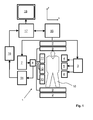
- a MR device 1 With reference to Figure 1 , a MR device 1 is shown.
- the device comprises superconducting or resistive main magnet coils 2 such that a substantially uniform, temporally constant main magnetic field is created along a z-axis through an examination volume.
- a magnetic resonance generation and manipulation system applies a series of RF pulses and switched magnetic field gradients to invert or excite nuclear magnetic spins, induce magnetic resonance, refocus magnetic resonance, manipulate magnetic resonance, spatially and otherwise encode the magnetic resonance, saturate spins, and the like to perform MR imaging.
- a gradient pulse amplifier 3 applies current pulses to selected ones of whole-body gradient coils 4, 5 and 6 along x, y and z-axes of the examination volume.
- a digital RF frequency transmitter 7 transmits RF pulses or pulse packets, via a send-/receive switch 8, to a whole-body volume RF coil 9 to transmit RF pulses into the examination volume.
- a typical MR imaging sequence is composed of a packet of RF pulse segments of short duration which taken together with each other and any applied magnetic field gradients achieve a selected manipulation of nuclear magnetic resonance.
- the RF pulses are used to saturate, excite resonance, invert magnetization, refocus resonance, or manipulate resonance and select a portion of a body 10 positioned in the examination volume.
- the MR signals are also picked up by the whole-body volume RF coil 9.
- a set of local array RF coils 11, 12, 13 are placed contiguous to the region selected for imaging.
- the array coils 11, 12, 13 can be used to receive MR signals induced by body-coil RF transmissions.
- the resultant MR signals are picked up by the whole body volume RF coil 9 and/or by the array RF coils 11, 12, 13 and demodulated by a receiver 14 preferably including a preamplifier (not shown).
- the receiver 14 is connected to the RF coils 9, 11, 12 and 13 via send-/receive switch 8.
- a host computer 15 controls the gradient pulse amplifier 3 and the transmitter 7 to generate any of a plurality of MR imaging sequences, such as echo planar imaging (EPI), echo volume imaging, gradient and spin echo imaging, fast spin echo imaging, and the like.
- EPI echo planar imaging
- the receiver 14 receives a single or a plurality of MR data lines in rapid succession following each RF excitation pulse.
- a data acquisition system 16 performs analog-to-digital conversion of the received signals and converts each MR data line to a digital format suitable for further processing. In modern MR devices the data acquisition system 16 is a separate computer which is specialized in acquisition of raw image data.
- the digital raw image data is reconstructed into an image representation by a reconstruction processor 17 which applies a Fourier transform or other appropriate reconstruction algorithms.
- the MR image may represent a planar slice through the patient, an array of parallel planar slices, a three-dimensional volume, or the like.
- the image is then stored in an image memory where it may be accessed for converting slices, projections, or other portions of the image representation into appropriate format for visualization, for example via a video monitor 18 which provides a man-readable display of the resultant MR image.
- the portion of the body 10 is subjected to a first imaging sequence for acquiring a first signal data set 19.
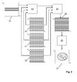
- the first signal data set 19 includes MR signals received via the volume RF coil 9. As illustrated in Figure 2 , only a central portion of k-space is sampled by means of the first imaging sequence. In the depicted embodiment the first signal data set 19 includes several k-space lines in the central portion of k-space that are equidistantly spaced in ky direction.
- the portion of the body 10 is subjected to a second imaging sequence for acquiring a second signal data set.
- the second signal data set includes sub-sets 20, 21, 22 of MR signal data received via the array RF coils 11, 12, 13, respectively.
- the second signal data set 20, 21, 22 covers both the central and peripheral portions of k-space.
- the second signal data set 20, 21, 22 is sampled at a reduced sampling density.
- the dashed lines in Figure 2 indicate k-space lines missing in the second signal data set 20, 21, 22.
- a set of weights is derived from the first signal data set 19 and the second signal data set 20, 21, 22 by fitting linear combinations of MR signals of the second signal data set 20, 21, 22 to MR signals of the first signal data set 19 at k-space positions missing in the second signal data set. This is illustrated in Figure 3 .
- the filled-out circles in the second signal data set 20, 21, 22 indicate acquired MR signals which are superposed by linear combination.
- the weights are determined by fitting this linear combination to MR signals of the first signal data set 19.
- the corresponding k-space position in the first signal data set 19 is indicated by the open circle in Figure 3 .
- the fitting procedure has to be performed on the basis of a sufficient number of k-space positions in the first signal data set 19 and the second signal data set 20, 21, 22 so as to ensure that the inverse problem to be solved is not underdetermined. To this end the k-space positions are congruently shifted in the first signal data set 19 and the second signal data set 20, 21, 22.
- S (1) (k) indicates a (complex) MR signal of the first signal data set 19
- S (2) l (k i ) indicates a MR signal of the second signal data set 20, 21, 22 received via one of the array coils 11, 12, 13.
- N c is the total number of array RF coils.
- n li represents the set of weights.
- the weights n li are determined by means of a common least squares fitting algorithm.
- the step of computation of the set of weights is indicated by reference number 23 in Figure 2 .
- step 24 the set of weights is applied for combining the MR signals received via the array RF coils 11, 12, 13, i.e. the MR signals of the second signal data set 20, 21, 22, into a third signal data set 25.
- linear combinations of the MR signals of the second signal data set, 20, 21, 22 are computed so as to obtain the third signal data set 25 with full k-space coverage and at full k-space density.
- S (3) (k) represents a (complex) MR signal of the third signal data set 25.
- the data synthesis is illustrated in Figure 4 .
- the filled-out circles again indicate k-space positions within the second signal data set 20, 21, 22 which are superposed in order to obtain k-space data at k y positions.
- a MR image 27 is reconstructed in a step 26, for example by means of Fourier transformation of the third signal data set 25.
- the method of the invention has the advantage that the computation time for the synthesis of the third data set scales linearly with the number of array RF coils used for MR signal acquisition since the method requires to estimate only one set of weights, and only one "target data set", i.e. the third signal data set 25 within the meaning of the invention, has to be synthesized. This leads to much faster reconstruction times in comparison to known approaches, such as GRAPPA.
- a further advantage is that phase information is preserved in the final MR image 27 because the first signal data set 19, i.e. the MR signals received via the volume RF coil 9, are used for deriving the set of weights.
- the acquisition time is reduced by the method of the invention because it is not necessary to fully sample the k-space center when acquiring the second signal data set 20, 21, 22, i.e. the MR data used for reconstruction of the final MR image 27.
- the second signal data set 20, 21, 22 can be acquired by uniform sub-sampling of k-space (in the k y direction in the depicted embodiment ), which has the advantage of a more uniform eddy current response and smooth weighting by relaxation decay of the MR signal as compared to a variable k-space density acquisition.
Landscapes
- Physics & Mathematics (AREA)
- Health & Medical Sciences (AREA)
- General Health & Medical Sciences (AREA)
- Nuclear Medicine, Radiotherapy & Molecular Imaging (AREA)
- Radiology & Medical Imaging (AREA)
- Engineering & Computer Science (AREA)
- Signal Processing (AREA)
- High Energy & Nuclear Physics (AREA)
- Condensed Matter Physics & Semiconductors (AREA)
- General Physics & Mathematics (AREA)
- Magnetic Resonance Imaging Apparatus (AREA)
Abstract
The invention relates to a method of MR imaging of at least an object (10) placed in an examination volume of a MR device (1). The method comprises the steps of:
- subjecting the object (10) to a first imaging sequence for acquiring a first signal data set (19), which first signal data set (19) includes MR signals received via a volume RF coil (9) having an essentially homogeneous spatial sensitivity profile within the examination volume, wherein the first imaging sequence comprises RF pulses and switched magnetic field gradients controlled in such a manner that only a central portion of k-space is sampled at a full sampling density;
- subjecting the object (10) to a second imaging sequence for acquiring a second signal data set (20, 21, 22), which second signal data set (20, 21, 22) includes MR signals received in parallel via a set of at least two array RF coils (11, 12, 13) having different spatial sensitivity profiles within the examination volume, wherein the second imaging sequence comprises RF pulses and switched magnetic field gradients controlled in such a manner that peripheral and central portions of k-space are sampled at a reduced sampling density;
- deriving a set of weights from the first signal data (19) set and the second signal data set (20, 21, 22);
- applying the set of weights for combining the MR signals received via the at least two array RF coils (11, 12, 13) into a third signal data set (25) in such a manner that the third signal data set (25) covers the peripheral and central portions of k-space at the full sampling density; and
- reconstructing a MR image (27) from the third signal data set (25). Moreover, the invention relates to a MR device for carrying out this method as well as to a computer program to be run on a MR device.
- subjecting the object (10) to a first imaging sequence for acquiring a first signal data set (19), which first signal data set (19) includes MR signals received via a volume RF coil (9) having an essentially homogeneous spatial sensitivity profile within the examination volume, wherein the first imaging sequence comprises RF pulses and switched magnetic field gradients controlled in such a manner that only a central portion of k-space is sampled at a full sampling density;
- subjecting the object (10) to a second imaging sequence for acquiring a second signal data set (20, 21, 22), which second signal data set (20, 21, 22) includes MR signals received in parallel via a set of at least two array RF coils (11, 12, 13) having different spatial sensitivity profiles within the examination volume, wherein the second imaging sequence comprises RF pulses and switched magnetic field gradients controlled in such a manner that peripheral and central portions of k-space are sampled at a reduced sampling density;
- deriving a set of weights from the first signal data (19) set and the second signal data set (20, 21, 22);
- applying the set of weights for combining the MR signals received via the at least two array RF coils (11, 12, 13) into a third signal data set (25) in such a manner that the third signal data set (25) covers the peripheral and central portions of k-space at the full sampling density; and
- reconstructing a MR image (27) from the third signal data set (25). Moreover, the invention relates to a MR device for carrying out this method as well as to a computer program to be run on a MR device.
Description
- The invention relates to the field of magnetic resonance (MR) imaging. It concerns a method of MR imaging of an object. The invention also relates to a MR device and to a computer program to be run on a MR device.
- Image-forming MR methods which utilize the interaction between magnetic fields and nuclear spins in order to form two-dimensional or three-dimensional images are widely used nowadays, notably in the field of medical diagnostics, because for imaging of soft tissue they are superior to other imaging methods in many respects, do not require ionizing radiation and are usually not invasive.
- According to the MR method in general, the object, for example the body of the patient to be examined, is arranged in a strong, uniform magnetic field whose direction at the same time defines an axis (normally the z-axis) of the co-ordinate system on which the measurement is based. The magnetic field produces different energy levels for the individual nuclear spins in dependence on the magnetic field strength which can be excited (spin resonance) by application of an electromagnetic alternating field (RF field) of defined frequency (so-called Larmor frequency, or MR frequency). From a macroscopic point of view the distribution of the individual nuclear spins produces an overall magnetization which can be deflected out of the state of equilibrium by application of an electromagnetic pulse of appropriate frequency (RF pulse), so that the magnetization performs a precessional motion about the z-axis. The precessional motion describes a surface of a cone whose angle of aperture is referred to as flip angle. The magnitude of the flip angle is dependent on the strength and the duration of the applied electromagnetic pulse. In the case of a so-called 90° pulse, the spins are deflected from the z axis to the transverse plane (flip angle 90°).
- After termination of the RF pulse, the magnetization relaxes back to the original state of equilibrium, in which the magnetization in the z direction is built up again with a first time constant T1 (spin lattice or longitudinal relaxation time), and the magnetization in the direction perpendicular to the z direction relaxes with a second time constant T2 (spin-spin or transverse relaxation time). The variation of the magnetization can be detected by means of receiving RF coils which are arranged and oriented within an examination volume of the MR device in such a manner that the variation of the magnetization is measured in the direction perpendicular to the z-axis. The decay of the transverse magnetization is accompanied, after application of, for example, a 90° pulse, by a transition of the nuclear spins (induced by local magnetic field inhomogeneities) from an ordered state with the same phase to a state in which all phase angles are uniformly distributed (dephasing). The dephasing can be compensated by means of a refocusing pulse (for example a 180° pulse). This produces an echo signal (spin echo) in the receiving coils.
- To realize spatial resolution in the body, constant magnetic field gradients extending along the three main axes are superposed on the uniform magnetic field, leading to a linear spatial dependency of the spin resonance frequency. The signal picked up in the receiving coils then contains components of different frequencies which can be associated with different locations in the body. The signal data obtained via the receiving coils corresponds to the spatial frequency domain and is called k-space data. The k-space data usually includes multiple lines acquired with different phase encoding. Each line is digitized by collecting a number of samples. A set of k-space data is converted to a MR image by means of an image reconstruction algorithm.
- Recently, techniques for accelerating MR acquisition have been developed which are called parallel acquisition. Methods in this category are SENSE (Sensitivity Encoding), SMASH (Simultaneous Acquisition of Spatial Harmonics), and GRAPPA (Generalized Auto-calibrating Partially Parallel Acquisition). SENSE, SMASH, and GRAPPA and other parallel acquisition techniques use undersampled k-space data acquisition obtained from multiple RF receiving coils in parallel. In these methods, the (complex) signal data from the multiple coils are combined with complex weightings in such a way as to suppress undersampling artifacts (aliasing) in the finally reconstructed MR images. This type of complex array signal combination is sometimes referred to as spatial filtering, and includes combining which is performed in the k-space domain (as in SMASH and GRAPPA) or in the image domain (as in SENSE), as well as methods which are hybrids.
- In SENSE, coil sensitivity profiles are estimated from low-resolution calibration images or data . This coil sensitivity information are then used to "unwrap" aliased pixels in image space using a direct inversion algorithm. GRAPPA falls into the category of auto-calibrating parallel MR imaging. In GRAPPA, a set of weights is calculated, which is necessary to synthesize k-space data which is missing (due to under-sampling) from acquired k-space data using an algorithm that does not require coil sensitivity estimates. The set of weights for GRAPPA is calculated from a small amount of fully sampled calibration data that is typically embedded within the acquisition of the under-sampled signal data. Auto-calibrating parallel imaging approaches are typically preferred in cases in which accurate coil sensitivity estimates cannot be obtained. Moreover, auto-calibrating parallel imaging techniques are known to exhibit a small amount of image artifacts in the finally reconstructed MR images.
- One drawback of GRAPPA and similar k-space based reconstruction schemes is that they are computationally demanding. In conventional GRAPPA reconstruction, a complete (i.e. fully sampled) signal data set is synthesized for each RF coil used for MR signal reception. A set of weights for signal synthesis has to be determined by fitting linear combinations of MR signals received via each RF coil to the acquired auto-calibration data. This process has to be repeated for each RF coil used for parallel image acquisition. Consequently, the computational complexity for MR image reconstruction scales with the number of RF coils used for signal acquisition. This is a serious limitation because presently a trend to use a large number of RF coils in parallel can be observed.
- A further issue is that in GRAPPA imaging a MR image is reconstructed from the MR signal data received via each individual RF coil. These separate coil images are then combined via a sum-of-squares reconstruction to obtain a final composite MR image. A drawback of this procedure is that only a magnitude image is reconstructed and the phase information is lost.
- The GRAPPA reconstruction approach is disclosed, for example, in
US 6,841,998 B1 . - From the foregoing it is readily appreciated that there is a need for an improved parallel MR imaging technique. It is consequently an object of the invention to enable fast parallel MR imaging at a reduced computational complexity.
- In accordance with the invention, a method of MR imaging of an obj ect placed in an examination volume of a MR device is disclosed. The method comprises the steps of:
- subj ecting the obj ect to a first imaging sequence for acquiring a first signal data set, which first signal data set includes MR signals received via a volume RF coil having an essentially homogeneous spatial sensitivity profile within the examination volume, wherein the first imaging sequence comprises RF pulses and switched magnetic field gradients controlled in such a manner that only a central portion of k-space is sampled at a full sampling density;
- subj ecting the obj ect to a second imaging sequence for acquiring a second signal data set, which second signal data set includes MR signals received in parallel via a set of at least two array RF coils having different spatial sensitivity profiles within the examination volume, wherein the second imaging sequence comprises RF pulses and switched magnetic field gradients controlled in such a manner that peripheral and central portions of k-space are sampled at a reduced sampling density;
- deriving a set of weights from the first signal data set and the second signal data set;
- applying the set of weights for combining the MR signals received via the at least two array RF coils into a third signal data set in such a manner that the third signal data set covers the peripheral and central portions of the k-space at the full sampling density; and
- reconstructing a MR image from the third signal data set.
- According to the invention, k-space is fully sampled only in its central portion and only via the volume RF coil, while the array RF coils are used for sampling the central and peripheral portions of k-space in a sub-sampled fashion, i.e. at a reduced sampling density. The set of weights required for synthesis of missing k-space data is derived from the data acquired via the volume RF coil and via the array RF coils. A third signal data set is synthesized from the sub-sampled MR signals received via the array RF coils, wherein the synthesized data covers the peripheral and central portions of k-space at the full sampling density. Finally, a MR image is reconstructed from the fully sampled synthesized data set.
- One advantage of the method of the invention is that only one set of weights has to be derived. Hence, the computational complexity is much reduced as compared to the conventional GRAPPA approach. This leads to much faster MR image reconstruction.
- A further advantage is that the phase information is fully preserved. This is because the MR signals received via the volume RF coil are used for derivation of the set of weights. Hence, there is no necessity to apply a sum-of-squares combination for reconstruction of the final MR image.
- Yet another advantage of the invention is that the second signal data, i.e. the MR signals received in parallel via the array RF coils, do not include embedded auto-calibration data. Consequently, the signal data can be acquired by uniform sub-sampling of k-space having the advantage of a uniform eddy current response and smooth weighting by signal decay as compared to the variable density acquisition which is applied in GRAPPA imaging.
- The method of the invention advantageously produces MR images at high acquisition and reconstruction speed in combination with high image quality and high signal-to noise ratio.
- It has to be noted that the method steps of the invention do not necessarily have to be performed in the above consecutive order. For example, also an interleaved operating scheme, in which k-space lines are alternately acquired via the volume RF coil and the array RF coils, is feasible. Hence, the first and second signal data set may be acquired (at least in part) simultaneously according to the invention.
- In accordance with the invention, k-space is sampled at a full sampling density during acquisition of the first signal data set. This means that the first signal data set fully covers a given field-of-view. During acquisition of the second signal data set the number of phase-encoding steps is reduced by a reduction factor R, typically by increasing the distance of equidistantly sampled k-space lines. This means that the second signal data set covers a reduced field-of-view which is smaller than the full field of view. In order to obtain the desired image resolution, both peripheral and central portions of k-space are sampled during acquisition of the second signal data set. During acquisition of the first signal data set, in contrast, only the central portion of k-space is sampled, which means that the first signal data set is acquired at a reduced resolution.
- According to a preferred embodiment of the invention, the set of weights is derived by fitting linear combinations of MR signals of the second signal data set to MR signals of the first signal data set. This means that the set of weights is derived from a relationship between the MR signals of the second signal data set and the MR signals of the first signal data set. In this manner, linear combination weights are generated that are usable for synthesis of k-space data received via the volume RF coil from k-space data received via the array RF coils. The set of weights derived in this manner can then be applied to compute linear combinations of MR signals of the second signal data set so as to obtain MR signals of the third signal data set. In this way, a new fully sampled third data set is computed from the undersampled second data set, which results in a full-field of-view MR image after Fourier transformation.
- The method of the invention described thus far can be carried out by means of a MR device including at least one main magnet coil for generating a uniform static magnetic field within an examination volume, a number of gradient coils for generating switched magnetic field gradients in different spatial directions within the examination volume, at least one volume RF coil which has an essentially homogeneous spatial sensitivity profile, for generating RF pulses within the examination volume and/or for receiving MR signals from an object positioned in the examination volume, a set of array RF coils for receiving MR signals from the body in parallel, the array RF coils having different spatial sensitivity profiles, a control unit for controlling the temporal succession of RF pulses and switched magnetic field gradients, and a reconstruction unit. The method of the invention can be implemented, for example, by a corresponding programming of the reconstruction unit and/or the control unit of the MR device.
- The method of the invention can be advantageously carried out in most MR devices in clinical use at present. To this end it is merely necessary to utilize a computer program by which the MR device is controlled such that it performs the above-explained method steps of the invention. The computer program may be present either on a data carrier or be present in a data network so as to be downloaded for installation in the control unit of the MR device.
- The enclosed drawings disclose preferred embodiments of the present invention. It should be understood, however, that the drawings are designed for the purpose of illustration only and not as a definition of the limits of the invention. In the drawings:
-
Fig. 1 shows a MR device for carrying out the method of the invention; -
Fig. 2 shows a block diagram illustrating the method of the invention; -
Fig. 3 shows a block diagram illustrating the computation of a set of weights according to the invention; -
Fig. 4 shows a diagram illustrating the synthesis of missing k-space data according to the invention. - With reference to
Figure 1 , aMR device 1 is shown. The device comprises superconducting or resistive main magnet coils 2 such that a substantially uniform, temporally constant main magnetic field is created along a z-axis through an examination volume. - A magnetic resonance generation and manipulation system applies a series of RF pulses and switched magnetic field gradients to invert or excite nuclear magnetic spins, induce magnetic resonance, refocus magnetic resonance, manipulate magnetic resonance, spatially and otherwise encode the magnetic resonance, saturate spins, and the like to perform MR imaging.
- Most specifically, a
gradient pulse amplifier 3 applies current pulses to selected ones of whole-body gradient coils 4, 5 and 6 along x, y and z-axes of the examination volume. A digitalRF frequency transmitter 7 transmits RF pulses or pulse packets, via a send-/receiveswitch 8, to a whole-bodyvolume RF coil 9 to transmit RF pulses into the examination volume. A typical MR imaging sequence is composed of a packet of RF pulse segments of short duration which taken together with each other and any applied magnetic field gradients achieve a selected manipulation of nuclear magnetic resonance. The RF pulses are used to saturate, excite resonance, invert magnetization, refocus resonance, or manipulate resonance and select a portion of abody 10 positioned in the examination volume. The MR signals are also picked up by the whole-bodyvolume RF coil 9. - For generation of MR images of limited regions of the
body 10 by means of parallel imaging, a set of local array RF coils 11, 12, 13 are placed contiguous to the region selected for imaging. The array coils 11, 12, 13 can be used to receive MR signals induced by body-coil RF transmissions. - The resultant MR signals are picked up by the whole body
volume RF coil 9 and/or by the array RF coils 11, 12, 13 and demodulated by areceiver 14 preferably including a preamplifier (not shown). Thereceiver 14 is connected to the RF coils 9, 11, 12 and 13 via send-/receiveswitch 8. - A
host computer 15 controls thegradient pulse amplifier 3 and thetransmitter 7 to generate any of a plurality of MR imaging sequences, such as echo planar imaging (EPI), echo volume imaging, gradient and spin echo imaging, fast spin echo imaging, and the like. For the selected sequence, thereceiver 14 receives a single or a plurality of MR data lines in rapid succession following each RF excitation pulse. Adata acquisition system 16 performs analog-to-digital conversion of the received signals and converts each MR data line to a digital format suitable for further processing. In modern MR devices thedata acquisition system 16 is a separate computer which is specialized in acquisition of raw image data. - Ultimately, the digital raw image data is reconstructed into an image representation by a
reconstruction processor 17 which applies a Fourier transform or other appropriate reconstruction algorithms. The MR image may represent a planar slice through the patient, an array of parallel planar slices, a three-dimensional volume, or the like. The image is then stored in an image memory where it may be accessed for converting slices, projections, or other portions of the image representation into appropriate format for visualization, for example via avideo monitor 18 which provides a man-readable display of the resultant MR image. - With continuing reference to
Figure 1 and with further reference toFigures 2 and3 , an embodiment of the imaging approach of the invention is explained. - According to the invention, the portion of the
body 10 is subjected to a first imaging sequence for acquiring a firstsignal data set 19. The first signal data set 19 includes MR signals received via thevolume RF coil 9. As illustrated inFigure 2 , only a central portion of k-space is sampled by means of the first imaging sequence. In the depicted embodiment the first signal data set 19 includes several k-space lines in the central portion of k-space that are equidistantly spaced in ky direction. - Moreover, the portion of the
body 10 is subjected to a second imaging sequence for acquiring a second signal data set. The second signal data set includessub-sets Figure 2 , the secondsignal data set signal data set signal data set Figure 2 indicate k-space lines missing in the secondsignal data set - A set of weights is derived from the first
signal data set 19 and the secondsignal data set signal data set Figure 3 . The filled-out circles in the secondsignal data set signal data set 19. The corresponding k-space position in the first signal data set 19 is indicated by the open circle inFigure 3 . The fitting procedure has to be performed on the basis of a sufficient number of k-space positions in the firstsignal data set 19 and the secondsignal data set signal data set 19 and the secondsignal data set signal data set 
- Herein, S(1)(k) indicates a (complex) MR signal of the first
signal data set 19, while S(2) l(ki) indicates a MR signal of the secondsignal data set signal data set Figure 3 ) within the first signal data set 19 can be selected. The number Nk has to be selected so as to find a good compromise between computation speed and image quality. n li represents the set of weights. The weights n li are determined by means of a common least squares fitting algorithm. The step of computation of the set of weights is indicated byreference number 23 inFigure 2 . Instep 24 the set of weights is applied for combining the MR signals received via the array RF coils 11, 12, 13, i.e. the MR signals of the secondsignal data set signal data set 25. To this end, linear combinations of the MR signals of the second signal data set, 20, 21, 22 are computed so as to obtain the third signal data set 25 with full k-space coverage and at full k-space density. The synthesis of MR signals of the third signal data set 25 can be written as follows:
- In this formula S(3) (k) represents a (complex) MR signal of the third
signal data set 25. The data synthesis is illustrated inFigure 4 . The filled-out circles again indicate k-space positions within the secondsignal data set MR image 27 is reconstructed in astep 26, for example by means of Fourier transformation of the thirdsignal data set 25. - It can be concluded that the method of the invention has the advantage that the computation time for the synthesis of the third data set scales linearly with the number of array RF coils used for MR signal acquisition since the method requires to estimate only one set of weights, and only one "target data set", i.e. the third signal data set 25 within the meaning of the invention, has to be synthesized. This leads to much faster reconstruction times in comparison to known approaches, such as GRAPPA. A further advantage is that phase information is preserved in the
final MR image 27 because the firstsignal data set 19, i.e. the MR signals received via thevolume RF coil 9, are used for deriving the set of weights. Also the acquisition time is reduced by the method of the invention because it is not necessary to fully sample the k-space center when acquiring the secondsignal data set final MR image 27. Moreover, the secondsignal data set
Claims (9)
- Method of MR imaging of an object (10) placed in an examination volume of a MR device (1), the method comprising the steps of- subjecting the object (10) to a first imaging sequence for acquiring a first signal data set (19), which first signal data set (19) includes MR signals received via a volume RF coil (9) having an essentially homogeneous spatial sensitivity profile within the examination volume, wherein the first imaging sequence comprises RF pulses and switched magnetic field gradients controlled in such a manner that only a central portion of k-space is sampled at a full sampling density;- subjecting the object (10) to a second imaging sequence for acquiring a second signal data set (20, 21, 22), which second signal data set (20, 21, 22) includes MR signals received in parallel via a set of at least two array RF coils (11, 12, 13) having different spatial sensitivity profiles within the examination volume, wherein the second imaging sequence comprises RF pulses and switched magnetic field gradients controlled in such a manner that peripheral and central portions of k-space are sampled at a reduced sampling density;- deriving a set of weights from the first signal data set (19) and the second signal data set (20, 21, 22);- applying the set of weights for combining the MR signals received via the at least two array RF coils (11, 12, 13) into a third signal data set (25) in such a manner that the third signal data set (25) covers the peripheral and central portions of k-space at the full sampling density; and- reconstructing a MR image (27) from the third signal data set (25).
- Method of claim 1, wherein the first signal data set covers a full field-of-view.
- Method of claim 2, wherein the second signal data set covers a reduced field-of-view which is smaller than the full field of view.
- Method of any one of claims 1-3, wherein the set of weights is derived by fitting linear combinations of MR signals of the second signal data set (20, 21, 22) to MR signals of the first signal data (19) at k-space positions missing in the second signal data set (20, 21, 22).
- Method of claim 4, wherein the set of weights is applied to compute linear combinations of MR signals of the second signal data set (20, 21, 22) so as to obtain MR signals of the third signal data set (25).
- MR device for carrying out the method claimed in claims 1-5, which MR device (1) includes at least one main magnet coil (2) for generating a uniform, static magnetic field within an examination volume, a number of gradient coils (4, 5, 6) for generating switched magnetic field gradients in different spatial directions within the examination volume, at least one volume RF coil (9), which has an essentially homogeneous spatial sensitivity profile, for generating RF pulses within the examination volume and/or for receiving MR signals from an object (10) positioned in the examination volume, a set of array RF coils (11, 12, 13) for receiving MR signals from the body (10) in parallel, the array RF coils (11, 12, 13) having different spatial sensitivity profiles, a control unit (15) for controlling the temporal succession of RF pulses and switched magnetic field gradients, and a reconstruction unit (17), wherein the MR device (1) is arranged to perform the following steps:- subjecting the object (10) to a first imaging sequence for acquiring a first signal data set (19), which first signal data set (19) includes MR signals received via the volume RF coil (9), wherein the first imaging sequence comprises RF pulses and switched magnetic field gradients controlled in such a manner that only a central portion of k-space is sampled at a full sampling density;- subjecting the object (10) to a second imaging sequence for acquiring a second signal data set (20, 21, 22), which second signal data set (20, 21, 22) includes MR signals received in parallel via the set of array RF coils (11, 12, 13), wherein the second imaging sequence comprises RF pulses and switched magnetic field gradients controlled in such a manner that peripheral and central portions of k-space are sampled at a reduced sampling density;- deriving a set of weights from the first signal data set (19) and the second signal data set (20, 21, 22);- applying the set of weights for combining the MR signals received via the at least two array RF coils (11, 12, 13) into a third signal data set (25) in such a manner that the third signal data set (25) covers the peripheral and central portions of k-space at the full sampling density; and- reconstructing a MR image (27) from the third signal data set (25).
- MR device of claim 6, wherein the volume RF coil (9) is a body coil.
- MR device of claim 6 or 7, wherein the array RF coils (11, 12, 13) are surface coils.
- Computer program to be run on a MR device, which computer program comprises instructions for:- generating a first imaging sequence for acquiring a first signal data set (19), wherein the first imaging sequence comprises RF pulses and switched magnetic field gradients controlled in such a manner that only a central portion of k-space is sampled at a full sampling density;- generating a second imaging sequence for acquiring a second signal data set (20, 21, 22), wherein the second imaging sequence comprises RF pulses and switched magnetic field gradients controlled in such a manner that peripheral and central portions of k-space are sampled at a reduced sampling density;- deriving a set of weights from the first signal data set (19) and the second signal data set (20, 21, 22);- applying the set of weights for combining MR signals comprised in the second signal data set (20, 21, 22) into a third signal data set (25) in such a manner that the third signal data set (25) covers the peripheral and central portions of k-space at the full sampling density; and- reconstructing a MR image (27) from the third signal data set (25).
Priority Applications (1)
| Application Number | Priority Date | Filing Date | Title |
|---|---|---|---|
| EP11184643.2A EP2581756A1 (en) | 2011-10-11 | 2011-10-11 | MR imaging using parallel signal acquisition |
Applications Claiming Priority (1)
| Application Number | Priority Date | Filing Date | Title |
|---|---|---|---|
| EP11184643.2A EP2581756A1 (en) | 2011-10-11 | 2011-10-11 | MR imaging using parallel signal acquisition |
Publications (1)
| Publication Number | Publication Date |
|---|---|
| EP2581756A1 true EP2581756A1 (en) | 2013-04-17 |
Family
ID=44983448
Family Applications (1)
| Application Number | Title | Priority Date | Filing Date |
|---|---|---|---|
| EP11184643.2A Withdrawn EP2581756A1 (en) | 2011-10-11 | 2011-10-11 | MR imaging using parallel signal acquisition |
Country Status (1)
| Country | Link |
|---|---|
| EP (1) | EP2581756A1 (en) |
Cited By (3)
| Publication number | Priority date | Publication date | Assignee | Title |
|---|---|---|---|---|
| WO2016003991A1 (en) * | 2014-06-30 | 2016-01-07 | Ge Medical Systems Global Technology Company, Llc | Software decoupling of an rf body coil and an rf surface coil |
| CN111295137A (en) * | 2018-03-20 | 2020-06-16 | 株式会社日立制作所 | Magnetic resonance imaging apparatus, sensitivity distribution calculation method, and sensitivity distribution calculation program |
| WO2024103414A1 (en) * | 2022-11-16 | 2024-05-23 | 中国科学院深圳先进技术研究院 | Method and apparatus for reconstructing magnetic resonance image |
Citations (4)
| Publication number | Priority date | Publication date | Assignee | Title |
|---|---|---|---|---|
| EP1102076A2 (en) * | 1999-11-15 | 2001-05-23 | Marconi Caswell Limited | Magnetic resonance imaging |
| US6841998B1 (en) | 2001-04-06 | 2005-01-11 | Mark Griswold | Magnetic resonance imaging method and apparatus employing partial parallel acquisition, wherein each coil produces a complete k-space datasheet |
| US20080012562A1 (en) * | 2006-07-11 | 2008-01-17 | The Board Of Trustees Of The Leland Stanford Junior University | Anti-aliased magnetic resonance image reconstruction using partially parallel encoded data |
| US7492153B2 (en) * | 2007-06-04 | 2009-02-17 | General Electric Company | System and method of parallel imaging with calibration to a separate coil |
-
2011
- 2011-10-11 EP EP11184643.2A patent/EP2581756A1/en not_active Withdrawn
Patent Citations (4)
| Publication number | Priority date | Publication date | Assignee | Title |
|---|---|---|---|---|
| EP1102076A2 (en) * | 1999-11-15 | 2001-05-23 | Marconi Caswell Limited | Magnetic resonance imaging |
| US6841998B1 (en) | 2001-04-06 | 2005-01-11 | Mark Griswold | Magnetic resonance imaging method and apparatus employing partial parallel acquisition, wherein each coil produces a complete k-space datasheet |
| US20080012562A1 (en) * | 2006-07-11 | 2008-01-17 | The Board Of Trustees Of The Leland Stanford Junior University | Anti-aliased magnetic resonance image reconstruction using partially parallel encoded data |
| US7492153B2 (en) * | 2007-06-04 | 2009-02-17 | General Electric Company | System and method of parallel imaging with calibration to a separate coil |
Non-Patent Citations (1)
| Title |
|---|
| DAVID J LARKMAN ET AL: "INVITED TOPICAL REVIEW; Parallel magnetic resonance imaging", PHYSICS IN MEDICINE AND BIOLOGY, TAYLOR AND FRANCIS LTD. LONDON, GB, vol. 52, no. 7, 7 April 2007 (2007-04-07), pages R15 - R55, XP020113275, ISSN: 0031-9155, DOI: 10.1088/0031-9155/52/7/R01 * |
Cited By (6)
| Publication number | Priority date | Publication date | Assignee | Title |
|---|---|---|---|---|
| WO2016003991A1 (en) * | 2014-06-30 | 2016-01-07 | Ge Medical Systems Global Technology Company, Llc | Software decoupling of an rf body coil and an rf surface coil |
| US10156617B2 (en) | 2014-06-30 | 2018-12-18 | General Electric Company | Magnetic resonance signal processing method, magnetic resonance signal processing apparatus and magnetic resonance apparatus, and program |
| CN111295137A (en) * | 2018-03-20 | 2020-06-16 | 株式会社日立制作所 | Magnetic resonance imaging apparatus, sensitivity distribution calculation method, and sensitivity distribution calculation program |
| CN111295137B (en) * | 2018-03-20 | 2024-01-26 | 富士胶片医疗健康株式会社 | Magnetic resonance imaging apparatus, sensitivity distribution calculation method, and storage medium |
| US12032050B2 (en) | 2018-03-20 | 2024-07-09 | Fujifilm Healthcare Corporation | Magnetic resonance imaging apparatus, sensitivity distribution calculation method, and sensitivity distribution calculation program |
| WO2024103414A1 (en) * | 2022-11-16 | 2024-05-23 | 中国科学院深圳先进技术研究院 | Method and apparatus for reconstructing magnetic resonance image |
Similar Documents
| Publication | Publication Date | Title |
|---|---|---|
| EP2689261B1 (en) | Compressed sensing mr image reconstruction using constraint from prior acquisition | |
| EP2411829B1 (en) | Mr imaging using parallel signal acquisition | |
| US11067653B2 (en) | Magnetic resonance imaging method including acquiring echo signals from each k-space slice with different relaxation time weightings after echo signals from different k-space splices are acquired | |
| US9223001B2 (en) | MR imaging using navigators | |
| EP2992351B1 (en) | Dixon-type water/fat separation mri using high-snr in-phase image and lower-snr at least partially out-of-phase image | |
| EP2798364B1 (en) | Mr imaging with suppression of flow artefacts | |
| JP7583858B2 (en) | Parallel multi-slice MR imaging | |
| EP2610632A1 (en) | MRI with Dixon-type water/fat separation and prior knowledge about inhomogeneity of the main magnetic field | |
| EP3295194B1 (en) | Parallel mr imaging with rf coil sensitivity mapping | |
| EP3044604B1 (en) | Metal resistant mr imaging | |
| EP3234624B1 (en) | Spin echo mr imaging | |
| WO2019162198A1 (en) | Dixon mr imaging using a multi-gradient-echo sequence | |
| US10732242B2 (en) | T2-weighted MR imaging with elimination of non-T2-weighted signal contributions | |
| WO2018114554A1 (en) | Dixon-type water/fat separation mr imaging | |
| EP2581756A1 (en) | MR imaging using parallel signal acquisition | |
| EP3185029A1 (en) | Mr imaging using propeller acquisition with t2 decay correction | |
| JP7559763B2 (en) | Parallel MR imaging using wave encoding | |
| US12140653B2 (en) | Dixon-type water/fat separation MR imaging |
Legal Events
| Date | Code | Title | Description |
|---|---|---|---|
| PUAI | Public reference made under article 153(3) epc to a published international application that has entered the european phase |
Free format text: ORIGINAL CODE: 0009012 |
|
| AK | Designated contracting states |
Kind code of ref document: A1 Designated state(s): AL AT BE BG CH CY CZ DE DK EE ES FI FR GB GR HR HU IE IS IT LI LT LU LV MC MK MT NL NO PL PT RO RS SE SI SK SM TR |
|
| AX | Request for extension of the european patent |
Extension state: BA ME |
|
| RAP1 | Party data changed (applicant data changed or rights of an application transferred) |
Owner name: KONINKLIJKE PHILIPS N.V. Owner name: PHILIPS INTELLECTUAL PROPERTY & STANDARDS GMBH |
|
| STAA | Information on the status of an ep patent application or granted ep patent |
Free format text: STATUS: THE APPLICATION IS DEEMED TO BE WITHDRAWN |
|
| 18D | Application deemed to be withdrawn |
Effective date: 20131018 |