EP2581644A1 - LED approach light - Google Patents
LED approach light Download PDFInfo
- Publication number
- EP2581644A1 EP2581644A1 EP11184491.6A EP11184491A EP2581644A1 EP 2581644 A1 EP2581644 A1 EP 2581644A1 EP 11184491 A EP11184491 A EP 11184491A EP 2581644 A1 EP2581644 A1 EP 2581644A1
- Authority
- EP
- European Patent Office
- Prior art keywords
- leds
- light
- module
- radiation pattern
- angle
- Prior art date
- Legal status (The legal status is an assumption and is not a legal conclusion. Google has not performed a legal analysis and makes no representation as to the accuracy of the status listed.)
- Granted
Links
Images
Classifications
-
- F—MECHANICAL ENGINEERING; LIGHTING; HEATING; WEAPONS; BLASTING
- F21—LIGHTING
- F21S—NON-PORTABLE LIGHTING DEVICES; SYSTEMS THEREOF; VEHICLE LIGHTING DEVICES SPECIALLY ADAPTED FOR VEHICLE EXTERIORS
- F21S8/00—Lighting devices intended for fixed installation
-
- B—PERFORMING OPERATIONS; TRANSPORTING
- B64—AIRCRAFT; AVIATION; COSMONAUTICS
- B64D—EQUIPMENT FOR FITTING IN OR TO AIRCRAFT; FLIGHT SUITS; PARACHUTES; ARRANGEMENT OR MOUNTING OF POWER PLANTS OR PROPULSION TRANSMISSIONS IN AIRCRAFT
- B64D2203/00—Aircraft or airfield lights using LEDs
-
- B—PERFORMING OPERATIONS; TRANSPORTING
- B64—AIRCRAFT; AVIATION; COSMONAUTICS
- B64F—GROUND OR AIRCRAFT-CARRIER-DECK INSTALLATIONS SPECIALLY ADAPTED FOR USE IN CONNECTION WITH AIRCRAFT; DESIGNING, MANUFACTURING, ASSEMBLING, CLEANING, MAINTAINING OR REPAIRING AIRCRAFT, NOT OTHERWISE PROVIDED FOR; HANDLING, TRANSPORTING, TESTING OR INSPECTING AIRCRAFT COMPONENTS, NOT OTHERWISE PROVIDED FOR
- B64F1/00—Ground or aircraft-carrier-deck installations
- B64F1/18—Visual or acoustic landing aids
- B64F1/20—Arrangement of optical beacons
-
- F—MECHANICAL ENGINEERING; LIGHTING; HEATING; WEAPONS; BLASTING
- F21—LIGHTING
- F21W—INDEXING SCHEME ASSOCIATED WITH SUBCLASSES F21K, F21L, F21S and F21V, RELATING TO USES OR APPLICATIONS OF LIGHTING DEVICES OR SYSTEMS
- F21W2111/00—Use or application of lighting devices or systems for signalling, marking or indicating, not provided for in codes F21W2102/00 – F21W2107/00
- F21W2111/04—Use or application of lighting devices or systems for signalling, marking or indicating, not provided for in codes F21W2102/00 – F21W2107/00 for waterways
-
- F—MECHANICAL ENGINEERING; LIGHTING; HEATING; WEAPONS; BLASTING
- F21—LIGHTING
- F21W—INDEXING SCHEME ASSOCIATED WITH SUBCLASSES F21K, F21L, F21S and F21V, RELATING TO USES OR APPLICATIONS OF LIGHTING DEVICES OR SYSTEMS
- F21W2111/00—Use or application of lighting devices or systems for signalling, marking or indicating, not provided for in codes F21W2102/00 – F21W2107/00
- F21W2111/06—Use or application of lighting devices or systems for signalling, marking or indicating, not provided for in codes F21W2102/00 – F21W2107/00 for aircraft runways or the like
-
- F—MECHANICAL ENGINEERING; LIGHTING; HEATING; WEAPONS; BLASTING
- F21—LIGHTING
- F21Y—INDEXING SCHEME ASSOCIATED WITH SUBCLASSES F21K, F21L, F21S and F21V, RELATING TO THE FORM OR THE KIND OF THE LIGHT SOURCES OR OF THE COLOUR OF THE LIGHT EMITTED
- F21Y2115/00—Light-generating elements of semiconductor light sources
- F21Y2115/10—Light-emitting diodes [LED]
Definitions
- the invention relates to a LED airport lights, preferably used as approach centerline lights or crossbar lights. It also relates to a method for emulating an elliptical radiation pattern.
- LED (light emitting diode) lighting systems offer significant advantages over traditional incandescent, HID and fluorescent lamps. LEDs are of smaller size, offer higher reliability, longer operational life and lower energy consumption. This is specifically important for airport lighting systems where high reliability and robustness is required. However, there are specific requirements when using LEDs. As increased operating temperature significantly reduces lifetime, cooling is of high importance. Furthermore, most LED chips are approximately isotropic light sources with a lambertian light distribution, which must be adapted to specific requirements of a lighting system.
- the problem to be solved by the invention is to provide a LED based airport light having a radiation pattern suitable for airport lights, like approach centerline lights or crossbar lights, further having high optical power, high reliability and lifetime. Furthermore, the solution should be inexpensive and suitable for manufacturing in large volumes. A further problem to be solved is to provide an elliptical radiation pattern without complex lenses and mirrors.
- an airport light has at least first and second LEDs forming at least two light beams.
- the first LEDs are mounted to a first module while the second LEDs are mounted to a second module.
- the first module and the second module are mounted in an angle against each other.
- the LEDs thus emit non-parallel light beams.
- the angle between the modules is selected such, that the light beams of first LEDs and second LEDs partially overlap and thereby approximate an elliptical radiation pattern.
- the preferred angle between the modules is in the range of 6° to 30°. In a preferred embodiment the angle between the modules is 8°. This is specifically preferred when using LEDs with an angle of +- 6° (equals 12° total) for 50% decrease of luminosity.
- the first and second modules may be any type of electronic module holding LEDs.
- they may be printed circuit boards. They may also be mechanically structures holding the LEDs, while the LEDs are electrically connected by discrete wires or a printed circuit board, preferably a flexible printed circuit board.
- the first and second modules are contained within a housing which preferably is made of metal to achieve good thermal conductivity. It preferably has a transparent cover which preferably is made of glass.
- additional modules are provided.
- the luminosity can be increased.
- the beam can be extended. For example it is possible to produce a comparatively broad and narrow ellipsis.
- Further modules may be arranged horizontally, vertically, or like a matrix.
- At least one of the first and second LEDs comprise of a plurality of LEDs, most preferably of 3 LEDs.
- the individual LEDs within at least one of first and second LEDs have slightly divergent light beams related to each other. This is also applicable to further modules.
- the housing has a module holder for holding the first of the second modules under the required angle.
- the module holder has to be changed. As the modules, or electronic modules have not to be changed, they can be manufactured in large quantities thus reducing manufacturing costs.
- Another aspect of the invention relates to a method for emulating an elliptical radiation pattern by LEDs which typically have a circular radiation pattern.
- the method comprises arranging first LEDs and second LEDs under an angle to obtain a first beam of light from the first LEDs and a second beam of light from the second LEDs.
- the first beam of light and the second beam of light are under the angle and form at least partially overlapping radiation patterns.
- the angle between the first and second LEDS is in the range of 6° to 30°.
- each of the LEDs is mounted at an individual module, and the modules are arranged under an angle relative to each other, defining the angle between the LEDs.
- additional modules are provided.
- the luminosity can be increased.
- the beam can be extended. For example it is possible to produce a comparatively broad and narrow ellipsis.
- At least one of the first and second LEDs comprise of a plurality of LEDs, most preferably of 3 LEDs.
- the individual LEDs within at least one of first and second LEDs have slightly divergent light beams related to each other. This is also applicable to further modules.
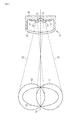
- the airport light 10 comprises a housing 60 which preferably is made of metal like aluminum to provide a good thermal conductivity.
- the housing is closed by a transparent cover 61 which preferably is made of glass.
- Inside the housing are a first module 11 and a second module 12.
- the first module 11 holds first LEDs 21, while the second module 12 holds second LEDs 22.
- the first module 11 and the second module 12 are mounted under an angle against each other. This results in a first angle 18 between the first module 11 and a center axis 70 different from 90°. Furthermore the second angle 19 between the second module 12 and the center axis 70 is also different from 90°.
- both angles are smaller than 90°.
- the angles may also be larger than 90°.
- the deviation of the angles from 90° is preferably in a range from 3° to 15°, resulting in an angle between the boards in a range from 6° to 30°. Most preferably the deviation is between 5° and 10°.
- the angles of the modules define the radiation angles of the LEDs attached thereto with respect to the center axis 70.
- the light beam 31 of first LEDs 21 result in first LEDs radiation pattern 41.
- the light beam 32 of second LED 22 recited in second LEDs radiation pattern 42.
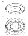
- FIG 2 a radiation pattern is shown as required by ICAO standards for approach centerline lights and for crossbar lights.
- the main beam 100 has an elliptical shape and is within a horizontal angular range of -10 degrees (left side) to +10 degrees (right side).
- the vertical range is from 2.5 degrees above ground (bottom) to 13.5 degrees.
- the luminosity of the main beam must not exceed 10000cd.
- Figure 3 shows the approximation of the above elliptical radiation pattern by two groups of circular radiation patterns.
- the first group of circular radiation patterns comprises radiation patterns 111, 112 and 113 which are generated by first LEDs 21.
- the second group of circular radiation patterns comprises radiation patterns 121, 122 and 1 to 3 which are generated by second LEDs 22.
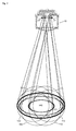
- FIG 4 the light beams for the radiation pattern are shown.
- the light being emitted from the first LEDs 21 results in radiation patterns 111, 112 and 113.
- the light being emitted from the second LEDs 22 recited radiation pattern 121, 122 and 123.
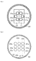
- first LEDs 21a, 21b and 21c are arranged on first module 11.
- Second LEDs 22a, 22b and 22c are arranged on the second module 12.
- Such an arrangement of LEDs may produce a radiation pattern as described above.
- first LEDs 21a, 21b and 21c are arranged on first module 11.
- Second LEDs 22a, 22b and 22c are arranged on the second 20 circuit board 12.
- Third LEDs 23a, 23b and 23c are arranged on the third module 13.Such an arrangement of LEDs may produce a broader radiation pattern as described above.
Landscapes
- Engineering & Computer Science (AREA)
- General Engineering & Computer Science (AREA)
- Non-Portable Lighting Devices Or Systems Thereof (AREA)
- Arrangement Of Elements, Cooling, Sealing, Or The Like Of Lighting Devices (AREA)
Abstract
Description
- The invention relates to a LED airport lights, preferably used as approach centerline lights or crossbar lights. It also relates to a method for emulating an elliptical radiation pattern.
- LED (light emitting diode) lighting systems offer significant advantages over traditional incandescent, HID and fluorescent lamps. LEDs are of smaller size, offer higher reliability, longer operational life and lower energy consumption. This is specifically important for airport lighting systems where high reliability and robustness is required. However, there are specific requirements when using LEDs. As increased operating temperature significantly reduces lifetime, cooling is of high importance. Furthermore, most LED chips are approximately isotropic light sources with a lambertian light distribution, which must be adapted to specific requirements of a lighting system.
- Most airport lights, specifically approach centerline lights or crossbar lights have tightly specified radiation patterns. In general these have to comply with the ICAO standards.
- In the US patent publication
US 6,932,496 B2 a LED-based elevated omnidirectional airfield light is disclosed. Light emitted by a centered LED is deflected radially by a mirror. - In the US patent publication
US 7,988,345 B2 a projection module of an automobile headlight is disclosed. Light emitted by LEDs is collimated and focused by a plurality of cascaded lenses to form a specific radiation pattern. This system may be adapted to a plurality of radiation pattern. The drawback is the very high complexity and resulting thereof high manufacturing costs and low reliability. - The problem to be solved by the invention is to provide a LED based airport light having a radiation pattern suitable for airport lights, like approach centerline lights or crossbar lights, further having high optical power, high reliability and lifetime. Furthermore, the solution should be inexpensive and suitable for manufacturing in large volumes. A further problem to be solved is to provide an elliptical radiation pattern without complex lenses and mirrors.
- Solutions of the problem are described in the independent claims. The dependent claims relate to further improvements of the invention.
- According to the invention an airport light has at least first and second LEDs forming at least two light beams. The first LEDs are mounted to a first module while the second LEDs are mounted to a second module. The first module and the second module are mounted in an angle against each other. The LEDs thus emit non-parallel light beams. The angle between the modules is selected such, that the light beams of first LEDs and second LEDs partially overlap and thereby approximate an elliptical radiation pattern. The preferred angle between the modules is in the range of 6° to 30°. In a preferred embodiment the angle between the modules is 8°. This is specifically preferred when using LEDs with an angle of +- 6° (equals 12° total) for 50% decrease of luminosity. This allows a simple and in expensive arrangement without complex and expensive optical means like lenses or reflectors. Although the resulting elliptical pattern is not perfect, it meets the minimum luminosity requirements of airfield lighting specifications like these issued by ICAO. In general the first and second modules may be any type of electronic module holding LEDs. In a very simple embodiment they may be printed circuit boards. They may also be mechanically structures holding the LEDs, while the LEDs are electrically connected by discrete wires or a printed circuit board, preferably a flexible printed circuit board. In a preferred embodiment, there is only one type of electronic module required. It is only necessary to mount the second module under an angle and rotated at 180° against the first module. The first and second modules are contained within a housing which preferably is made of metal to achieve good thermal conductivity. It preferably has a transparent cover which preferably is made of glass.
- In another embodiment additional modules are provided. With further modules the luminosity can be increased. Furthermore the beam can be extended. For example it is possible to produce a comparatively broad and narrow ellipsis. Further modules may be arranged horizontally, vertically, or like a matrix.
- In a preferred embodiment at least one of the first and second LEDs comprise of a plurality of LEDs, most preferably of 3 LEDs. For an improved approximation of the elliptical radiation pattern it is preferred, if the individual LEDs within at least one of first and second LEDs have slightly divergent light beams related to each other. This is also applicable to further modules.
- In a further embodiment the housing has a module holder for holding the first of the second modules under the required angle. To adapt the radiation pattern to individual requirements only the module holder has to be changed. As the modules, or electronic modules have not to be changed, they can be manufactured in large quantities thus reducing manufacturing costs.
- Another aspect of the invention relates to a method for emulating an elliptical radiation pattern by LEDs which typically have a circular radiation pattern. The method comprises arranging first LEDs and second LEDs under an angle to obtain a first beam of light from the first LEDs and a second beam of light from the second LEDs. The first beam of light and the second beam of light are under the angle and form at least partially overlapping radiation patterns. Preferably the angle between the first and second LEDS is in the range of 6° to 30°.
- In a preferred embodiment each of the LEDs is mounted at an individual module, and the modules are arranged under an angle relative to each other, defining the angle between the LEDs.
- In another embodiment additional modules are provided. With further modules the luminosity can be increased. Furthermore the beam can be extended. For example it is possible to produce a comparatively broad and narrow ellipsis.
- In a further embodiment, at least one of the first and second LEDs comprise of a plurality of LEDs, most preferably of 3 LEDs. For an improved approximation of the elliptical radiation pattern it is preferred, if the individual LEDs within at least one of first and second LEDs have slightly divergent light beams related to each other. This is also applicable to further modules.
- In the following the invention will be described by way of example, without limitation of the general inventive concept, on examples of embodiment with reference to the drawings.
- Figure 1
- shows an embodiment of the invention.
- Figure 2
- shows a radiation pattern as required by standards.
- Figure 3
- shows the approximation of an elliptical radiation pattern by circular radiation patterns.
- Figure 4
- shows the light beams approximating an elliptical radiation pattern.
- Figure 5
- shows an exemplary arrangement of LEDs.
- An embodiment of the invention is shown in
figure 1 . Theairport light 10 comprises ahousing 60 which preferably is made of metal like aluminum to provide a good thermal conductivity. The housing is closed by atransparent cover 61 which preferably is made of glass. Inside the housing are afirst module 11 and asecond module 12. Thefirst module 11 holdsfirst LEDs 21, while thesecond module 12 holdssecond LEDs 22. There may be additional electronic components like resistors, diodes or LED drivers on the modules. Thefirst module 11 and thesecond module 12 are mounted under an angle against each other. This results in afirst angle 18 between thefirst module 11 and acenter axis 70 different from 90°. Furthermore thesecond angle 19 between thesecond module 12 and thecenter axis 70 is also different from 90°. As shown herein both angles are smaller than 90°. The angles may also be larger than 90°. The deviation of the angles from 90° is preferably in a range from 3° to 15°, resulting in an angle between the boards in a range from 6° to 30°. Most preferably the deviation is between 5° and 10°. The angles of the modules define the radiation angles of the LEDs attached thereto with respect to thecenter axis 70. Thelight beam 31 offirst LEDs 21 result in firstLEDs radiation pattern 41. Thelight beam 32 ofsecond LED 22 recited in secondLEDs radiation pattern 42. By superimposing the first and the second radiation pattern, the minimum required luminosity as shown by theelliptical radiation pattern 50 can be maintained. - In
figure 2 a radiation pattern is shown as required by ICAO standards for approach centerline lights and for crossbar lights. Themain beam 100 has an elliptical shape and is within a horizontal angular range of -10 degrees (left side) to +10 degrees (right side). The vertical range is from 2.5 degrees above ground (bottom) to 13.5 degrees. The luminosity of the main beam must not exceed 10000cd. There further a firstouter beam 101 and a secondouter beam 102. The luminosity is decreasing from the main beam to the outer beams. -
Figure 3 shows the approximation of the above elliptical radiation pattern by two groups of circular radiation patterns. The first group of circular radiation patterns comprisesradiation patterns first LEDs 21. The second group of circular radiation patterns comprisesradiation patterns second LEDs 22. By superimposing the radiation of six LEDs a comparatively good approximation of the required elliptical radiation pattern can be achieved. For example in the center area of the main beam light of all six LEDs is superimposed, resulting in the highest luminosity. In the outer areas like in the area of secondouter beam 102 there is light of the lower number of LEDs superimposed. For example at the right and the left side there is only light of one LED 112-or 122. - In
figure 4 the light beams for the radiation pattern are shown. The light being emitted from thefirst LEDs 21 results inradiation patterns second LEDs 22 recitedradiation pattern - In
figure 5 an exemplary arrangement of LEDs is shown. Herefirst LEDs first module 11.Second LEDs second module 12. Such an arrangement of LEDs may produce a radiation pattern as described above. - In
figure 6 an arrangement of 3 LED modules is shown. Herefirst LEDs first module 11.Second LEDs circuit board 12.Third LEDs -
- 10
- airport light
- 11
- first module
- 12
- second module
- 13
- third module
- 18
- first angle
- 19
- second angle
- 21
- first LEDs
- 22
- second LEDs
- 23
- third LEDs
- 31
- beam of light by first LEDs
- 32
- beam of light by second LEDs
- 41
- first LEDs radiation pattern
- 42
- second LEDs radiation pattern
- 50
- required elliptical radiation pattern
- 60
- housing
- 61
- transparent cover
- 70
- center axis
- 100
- main beam
- 101
- first outer beam
- 102
- second outer beam
- 111, 112, 113
- radiation patterns of first LEDs
- 121, 122, 123
- radiation patterns of second LEDs
Claims (11)
- An airport light (10) comprising at least
a housing (60) covered by a transparent cover (61) and containing
a first module (11) with first LEDs (21), generating a first beam of light (31),
a second module (12) with a second LEDs (22), generating a second beam of light (32),
the first module (11) mounted under an angle to the second module (12) resulting in non--parallel and partially overlapping first beam of light (31) and a second beam of light (32),
the partially overlapping beams of light approximating an elliptical radiation pattern. - The airport light (10) according to claim 1,
characterized in, that
at least a third module (13) with third LEDs (23) producing at least a third beam of light partially overlapping any one beam of another LED is provided. - The airport light (10) according to any one of the preceding claims,
characterized in, that
at least the first LEDs (21) and/or the second LEDs (22) comprise of a plurality of LEDs. - The airport light (10) according to claim 3,
characterized in, that
at least the first LEDs (21) and the second LEDs (22) each comprise of three LEDs. - The airport light (10) according to any one of the preceding claims,
characterized in, that
the housing (60) comprises metal. - A method for emulating an elliptical radiation pattern by LEDs (21, 22) having a circular radiation pattern, comprising the step of: arranging first LEDs (21) and second LEDs (22) under an angle to obtain a first beam of light (31) from the first LEDs and a second beam of light (32) from the second LEDs, wherein the first beam of light and the second beam of light at least partially overlap.
- The method according to claim 6,
characterized in, that
the angle between the first and second LEDs is in the range of 6° to 30 °. - The method according to claims 6 or 7,
characterized in, that
each of the LEDs (21, 22) is mounted at an individual module (11, 12), and the modules (11, 12) are arranged under an angle relative to each other, defining the angle between the LEDs. - The method according to any one of claims 6 to 8,
characterized in, that
at least a third module (13) with third LEDs (23) producing at least a third beam of light partially overlapping any one beam of another LED is provided. - The method according to any one of claims 6 to 9,
characterized in, that
at least the first LEDs (21) and/or the second LEDs (22) comprise of a plurality of LEDs. - The method according to claim 10,
characterized in, that
at least the first LEDs (21) and the second LEDs (22) each comprise of three LEDs.
Priority Applications (5)
| Application Number | Priority Date | Filing Date | Title |
|---|---|---|---|
| EP11184491.6A EP2581644B1 (en) | 2011-10-10 | 2011-10-10 | LED approach light |
| CN201280050292.9A CN103874877A (en) | 2011-10-10 | 2012-10-09 | LED approach light |
| PCT/EP2012/069968 WO2013053710A1 (en) | 2011-10-10 | 2012-10-09 | Led approach light |
| KR1020147012727A KR20140103911A (en) | 2011-10-10 | 2012-10-09 | Led approach light |
| US14/248,722 US20140218917A1 (en) | 2011-10-10 | 2014-04-09 | LED Approach Light |
Applications Claiming Priority (1)
| Application Number | Priority Date | Filing Date | Title |
|---|---|---|---|
| EP11184491.6A EP2581644B1 (en) | 2011-10-10 | 2011-10-10 | LED approach light |
Publications (2)
| Publication Number | Publication Date |
|---|---|
| EP2581644A1 true EP2581644A1 (en) | 2013-04-17 |
| EP2581644B1 EP2581644B1 (en) | 2018-03-21 |
Family
ID=46982624
Family Applications (1)
| Application Number | Title | Priority Date | Filing Date |
|---|---|---|---|
| EP11184491.6A Active EP2581644B1 (en) | 2011-10-10 | 2011-10-10 | LED approach light |
Country Status (5)
| Country | Link |
|---|---|
| US (1) | US20140218917A1 (en) |
| EP (1) | EP2581644B1 (en) |
| KR (1) | KR20140103911A (en) |
| CN (1) | CN103874877A (en) |
| WO (1) | WO2013053710A1 (en) |
Families Citing this family (2)
| Publication number | Priority date | Publication date | Assignee | Title |
|---|---|---|---|---|
| DE102013005932A1 (en) * | 2013-04-05 | 2014-10-23 | Cooper Crouse-Hinds Gmbh | LED module, luminaire with such and method for influencing a light spectrum |
| CN104819403A (en) * | 2014-10-22 | 2015-08-05 | 深圳市科曼医疗设备有限公司 | Lighting assembly of operating lamp, operating lamp and light spot adjusting method for operating lamp |
Citations (3)
| Publication number | Priority date | Publication date | Assignee | Title |
|---|---|---|---|---|
| US6932496B2 (en) | 2002-04-16 | 2005-08-23 | Farlight Llc | LED-based elevated omnidirectional airfield light |
| US20090016069A1 (en) * | 2006-11-01 | 2009-01-15 | Mcdermott Kevin | Broad beam light |
| US7988345B2 (en) | 2007-08-29 | 2011-08-02 | Automotive Lighting Reutlingen Gmbh | Projection module of an automobile headlight |
Family Cites Families (26)
| Publication number | Priority date | Publication date | Assignee | Title |
|---|---|---|---|---|
| US4382274A (en) * | 1981-12-15 | 1983-05-03 | Societe Anonyme Des Etablissements Adrien De Backer | Flush runway inset top assembly for airport guidance light apparatus and guidance light apparatus comprising a top assembly of this type |
| JPH10241418A (en) * | 1997-02-21 | 1998-09-11 | Toshiba Corp | Lighting equipment |
| FR2797940B1 (en) * | 1999-08-31 | 2001-12-28 | Jerome Greggory | IMPROVED LIGHTING DEVICE FOR A BEACON, ESPECIALLY AN AIRPORT MANEUVER AREA |
| US6354714B1 (en) * | 2000-04-04 | 2002-03-12 | Michael Rhodes | Embedded led lighting system |
| US6431728B1 (en) * | 2000-07-05 | 2002-08-13 | Whelen Engineering Company, Inc. | Multi-array LED warning lights |
| DE50010570D1 (en) * | 2000-10-11 | 2005-07-21 | Swarovski & Co | Marking element for roadways |
| US20050068765A1 (en) * | 2003-09-26 | 2005-03-31 | Juan Antonio Ertze Encinas | Outdoors self sufficient uninterruptable luminaire |
| US7414546B2 (en) * | 2004-07-08 | 2008-08-19 | Honeywell International Inc. | White anti-collision light utilizing light-emitting diode (LED) technology |
| US7357530B2 (en) * | 2005-07-15 | 2008-04-15 | Bwt Property, Inc. | Lighting apparatus for navigational aids |
| EP1945999B1 (en) * | 2005-10-19 | 2016-07-27 | Martin Professional ApS | Improvements in or relating to light assemblies |
| US7766508B2 (en) * | 2006-09-12 | 2010-08-03 | Cree, Inc. | LED lighting fixture |
| CN201066108Y (en) * | 2007-01-10 | 2008-05-28 | 宁波安迪光电科技有限公司 | LED spotlight |
| US7824067B2 (en) * | 2007-03-21 | 2010-11-02 | Thomas & Betts International, Inc. | Emergency light fixture having an efficient reflector assembly |
| CN201382346Y (en) * | 2007-11-21 | 2010-01-13 | 朱先利 | Vehicle safe turning signal lamp and supporting device |
| JP5263658B2 (en) * | 2007-11-30 | 2013-08-14 | 東芝ライテック株式会社 | Lighting device |
| TW200938762A (en) * | 2008-03-14 | 2009-09-16 | xue-zhong Gao | Assembly of light emitting unit |
| KR100999162B1 (en) * | 2008-03-24 | 2010-12-07 | 주식회사 아모럭스 | Lighting device using light emitting diode |
| US20100046226A1 (en) * | 2008-06-18 | 2010-02-25 | Cooper Technologies Company | Light Fixture With An Adjustable Optical Distribution |
| US20090323343A1 (en) * | 2008-06-30 | 2009-12-31 | Pei-Choa Wang | Lamp base improvement of a street lamp |
| DE102008052869B4 (en) * | 2008-09-15 | 2014-06-26 | Siteco Beleuchtungstechnik Gmbh | Luminaire with LED mounting rail |
| KR20100070488A (en) * | 2008-12-18 | 2010-06-28 | 주식회사 포유 | Led streetright |
| US8414155B2 (en) * | 2009-03-18 | 2013-04-09 | Koninklijke Philips Electronics N.V. | LED luminaire |
| JP2012523664A (en) * | 2009-04-08 | 2012-10-04 | ジーエル ビジョン インコーポレイテッド | LED lighting with wide and uniform light distribution |
| KR20100120032A (en) * | 2009-05-04 | 2010-11-12 | 주식회사 프리마텍 | Light emitting diode lamp for adjusting direction angle |
| DE102010006248B3 (en) * | 2010-01-28 | 2011-07-14 | Franz Sill GmbH, 10969 | LED facade spotlight |
| US9068707B1 (en) * | 2010-04-06 | 2015-06-30 | Musco Corporation | Compact LED light source and lighting system |
-
2011
- 2011-10-10 EP EP11184491.6A patent/EP2581644B1/en active Active
-
2012
- 2012-10-09 WO PCT/EP2012/069968 patent/WO2013053710A1/en not_active Ceased
- 2012-10-09 CN CN201280050292.9A patent/CN103874877A/en active Pending
- 2012-10-09 KR KR1020147012727A patent/KR20140103911A/en not_active Withdrawn
-
2014
- 2014-04-09 US US14/248,722 patent/US20140218917A1/en not_active Abandoned
Patent Citations (3)
| Publication number | Priority date | Publication date | Assignee | Title |
|---|---|---|---|---|
| US6932496B2 (en) | 2002-04-16 | 2005-08-23 | Farlight Llc | LED-based elevated omnidirectional airfield light |
| US20090016069A1 (en) * | 2006-11-01 | 2009-01-15 | Mcdermott Kevin | Broad beam light |
| US7988345B2 (en) | 2007-08-29 | 2011-08-02 | Automotive Lighting Reutlingen Gmbh | Projection module of an automobile headlight |
Also Published As
| Publication number | Publication date |
|---|---|
| CN103874877A (en) | 2014-06-18 |
| EP2581644B1 (en) | 2018-03-21 |
| WO2013053710A1 (en) | 2013-04-18 |
| US20140218917A1 (en) | 2014-08-07 |
| KR20140103911A (en) | 2014-08-27 |
Similar Documents
| Publication | Publication Date | Title |
|---|---|---|
| CN102563507B (en) | Improve the spotlight of performance | |
| US8033683B2 (en) | Staggered LED based high-intensity light | |
| US8096677B2 (en) | Staggered LED based high-intensity light | |
| EP2450279B1 (en) | LED lighting device of an aircraft, in particular for manoeuvres of landing, take-off, taxiing, and searching, and aircraft comprising said device | |
| US20100091507A1 (en) | Directed LED Light With Reflector | |
| EP2433047B1 (en) | Lighting device with multiple-region reflector | |
| CN101592302B (en) | Real loading LED module for motor vehicle rear assembled lamp | |
| US9562677B2 (en) | LED lamp having at least two sectors | |
| US8696156B2 (en) | LED light bulb with light scattering optics structure | |
| US8814384B2 (en) | Light having LED modules | |
| US9074746B2 (en) | Non-uniform multi-faceted reflector for rear combination lamp providing sparkle effect | |
| US9791129B2 (en) | Hybrid light assembly | |
| EP1510457B1 (en) | Anti collision light for aircraft | |
| US20170146211A1 (en) | Lighting device | |
| US7040786B2 (en) | Anticollision light for aircraft | |
| US9964260B2 (en) | LED lighting device with improved light distribution | |
| EP2581644B1 (en) | LED approach light | |
| EP2071640A1 (en) | Lighting device | |
| US20070159420A1 (en) | A Power LED Light Source | |
| EP2573450B1 (en) | Airport and heliport lighting system | |
| US10655807B2 (en) | Method and apparatus for vehicle lighting | |
| KR200455638Y1 (en) | LED lamp |
Legal Events
| Date | Code | Title | Description |
|---|---|---|---|
| PUAI | Public reference made under article 153(3) epc to a published international application that has entered the european phase |
Free format text: ORIGINAL CODE: 0009012 |
|
| AK | Designated contracting states |
Kind code of ref document: A1 Designated state(s): AL AT BE BG CH CY CZ DE DK EE ES FI FR GB GR HR HU IE IS IT LI LT LU LV MC MK MT NL NO PL PT RO RS SE SI SK SM TR |
|
| AX | Request for extension of the european patent |
Extension state: BA ME |
|
| 17P | Request for examination filed |
Effective date: 20130730 |
|
| RBV | Designated contracting states (corrected) |
Designated state(s): AL AT BE BG CH CY CZ DE DK EE ES FI FR GB GR HR HU IE IS IT LI LT LU LV MC MK MT NL NO PL PT RO RS SE SI SK SM TR |
|
| 17Q | First examination report despatched |
Effective date: 20131107 |
|
| STAA | Information on the status of an ep patent application or granted ep patent |
Free format text: STATUS: EXAMINATION IS IN PROGRESS |
|
| RAP1 | Party data changed (applicant data changed or rights of an application transferred) |
Owner name: INDUPERM A/S |
|
| REG | Reference to a national code |
Ref country code: DE Ref legal event code: R079 Ref document number: 602011046641 Country of ref document: DE Free format text: PREVIOUS MAIN CLASS: F21S0008000000 Ipc: B64F0001200000 |
|
| RIC1 | Information provided on ipc code assigned before grant |
Ipc: F21W 111/04 20060101ALI20170531BHEP Ipc: F21S 8/00 20060101ALI20170531BHEP Ipc: B64F 1/20 20060101AFI20170531BHEP Ipc: F21Y 115/10 20160101ALI20170531BHEP Ipc: F21W 111/06 20060101ALI20170531BHEP |
|
| GRAP | Despatch of communication of intention to grant a patent |
Free format text: ORIGINAL CODE: EPIDOSNIGR1 |
|
| STAA | Information on the status of an ep patent application or granted ep patent |
Free format text: STATUS: GRANT OF PATENT IS INTENDED |
|
| INTG | Intention to grant announced |
Effective date: 20170911 |
|
| GRAS | Grant fee paid |
Free format text: ORIGINAL CODE: EPIDOSNIGR3 |
|
| GRAJ | Information related to disapproval of communication of intention to grant by the applicant or resumption of examination proceedings by the epo deleted |
Free format text: ORIGINAL CODE: EPIDOSDIGR1 |
|
| GRAL | Information related to payment of fee for publishing/printing deleted |
Free format text: ORIGINAL CODE: EPIDOSDIGR3 |
|
| STAA | Information on the status of an ep patent application or granted ep patent |
Free format text: STATUS: EXAMINATION IS IN PROGRESS |
|
| GRAR | Information related to intention to grant a patent recorded |
Free format text: ORIGINAL CODE: EPIDOSNIGR71 |
|
| STAA | Information on the status of an ep patent application or granted ep patent |
Free format text: STATUS: GRANT OF PATENT IS INTENDED |
|
| GRAA | (expected) grant |
Free format text: ORIGINAL CODE: 0009210 |
|
| STAA | Information on the status of an ep patent application or granted ep patent |
Free format text: STATUS: THE PATENT HAS BEEN GRANTED |
|
| INTC | Intention to grant announced (deleted) | ||
| INTG | Intention to grant announced |
Effective date: 20180207 |
|
| AK | Designated contracting states |
Kind code of ref document: B1 Designated state(s): AL AT BE BG CH CY CZ DE DK EE ES FI FR GB GR HR HU IE IS IT LI LT LU LV MC MK MT NL NO PL PT RO RS SE SI SK SM TR |
|
| REG | Reference to a national code |
Ref country code: GB Ref legal event code: FG4D |
|
| REG | Reference to a national code |
Ref country code: CH Ref legal event code: EP |
|
| REG | Reference to a national code |
Ref country code: AT Ref legal event code: REF Ref document number: 980809 Country of ref document: AT Kind code of ref document: T Effective date: 20180415 |
|
| REG | Reference to a national code |
Ref country code: IE Ref legal event code: FG4D |
|
| REG | Reference to a national code |
Ref country code: DE Ref legal event code: R096 Ref document number: 602011046641 Country of ref document: DE |
|
| REG | Reference to a national code |
Ref country code: NL Ref legal event code: MP Effective date: 20180321 |
|
| PG25 | Lapsed in a contracting state [announced via postgrant information from national office to epo] |
Ref country code: FI Free format text: LAPSE BECAUSE OF FAILURE TO SUBMIT A TRANSLATION OF THE DESCRIPTION OR TO PAY THE FEE WITHIN THE PRESCRIBED TIME-LIMIT Effective date: 20180321 Ref country code: NO Free format text: LAPSE BECAUSE OF FAILURE TO SUBMIT A TRANSLATION OF THE DESCRIPTION OR TO PAY THE FEE WITHIN THE PRESCRIBED TIME-LIMIT Effective date: 20180621 Ref country code: CY Free format text: LAPSE BECAUSE OF FAILURE TO SUBMIT A TRANSLATION OF THE DESCRIPTION OR TO PAY THE FEE WITHIN THE PRESCRIBED TIME-LIMIT Effective date: 20180321 Ref country code: HR Free format text: LAPSE BECAUSE OF FAILURE TO SUBMIT A TRANSLATION OF THE DESCRIPTION OR TO PAY THE FEE WITHIN THE PRESCRIBED TIME-LIMIT Effective date: 20180321 Ref country code: LT Free format text: LAPSE BECAUSE OF FAILURE TO SUBMIT A TRANSLATION OF THE DESCRIPTION OR TO PAY THE FEE WITHIN THE PRESCRIBED TIME-LIMIT Effective date: 20180321 |
|
| REG | Reference to a national code |
Ref country code: LT Ref legal event code: MG4D |
|
| REG | Reference to a national code |
Ref country code: AT Ref legal event code: MK05 Ref document number: 980809 Country of ref document: AT Kind code of ref document: T Effective date: 20180321 |
|
| PG25 | Lapsed in a contracting state [announced via postgrant information from national office to epo] |
Ref country code: BG Free format text: LAPSE BECAUSE OF FAILURE TO SUBMIT A TRANSLATION OF THE DESCRIPTION OR TO PAY THE FEE WITHIN THE PRESCRIBED TIME-LIMIT Effective date: 20180621 Ref country code: SE Free format text: LAPSE BECAUSE OF FAILURE TO SUBMIT A TRANSLATION OF THE DESCRIPTION OR TO PAY THE FEE WITHIN THE PRESCRIBED TIME-LIMIT Effective date: 20180321 Ref country code: LV Free format text: LAPSE BECAUSE OF FAILURE TO SUBMIT A TRANSLATION OF THE DESCRIPTION OR TO PAY THE FEE WITHIN THE PRESCRIBED TIME-LIMIT Effective date: 20180321 Ref country code: RS Free format text: LAPSE BECAUSE OF FAILURE TO SUBMIT A TRANSLATION OF THE DESCRIPTION OR TO PAY THE FEE WITHIN THE PRESCRIBED TIME-LIMIT Effective date: 20180321 Ref country code: GR Free format text: LAPSE BECAUSE OF FAILURE TO SUBMIT A TRANSLATION OF THE DESCRIPTION OR TO PAY THE FEE WITHIN THE PRESCRIBED TIME-LIMIT Effective date: 20180622 |
|
| REG | Reference to a national code |
Ref country code: FR Ref legal event code: PLFP Year of fee payment: 8 |
|
| PG25 | Lapsed in a contracting state [announced via postgrant information from national office to epo] |
Ref country code: RO Free format text: LAPSE BECAUSE OF FAILURE TO SUBMIT A TRANSLATION OF THE DESCRIPTION OR TO PAY THE FEE WITHIN THE PRESCRIBED TIME-LIMIT Effective date: 20180321 Ref country code: EE Free format text: LAPSE BECAUSE OF FAILURE TO SUBMIT A TRANSLATION OF THE DESCRIPTION OR TO PAY THE FEE WITHIN THE PRESCRIBED TIME-LIMIT Effective date: 20180321 Ref country code: IT Free format text: LAPSE BECAUSE OF FAILURE TO SUBMIT A TRANSLATION OF THE DESCRIPTION OR TO PAY THE FEE WITHIN THE PRESCRIBED TIME-LIMIT Effective date: 20180321 Ref country code: ES Free format text: LAPSE BECAUSE OF FAILURE TO SUBMIT A TRANSLATION OF THE DESCRIPTION OR TO PAY THE FEE WITHIN THE PRESCRIBED TIME-LIMIT Effective date: 20180321 Ref country code: AL Free format text: LAPSE BECAUSE OF FAILURE TO SUBMIT A TRANSLATION OF THE DESCRIPTION OR TO PAY THE FEE WITHIN THE PRESCRIBED TIME-LIMIT Effective date: 20180321 Ref country code: NL Free format text: LAPSE BECAUSE OF FAILURE TO SUBMIT A TRANSLATION OF THE DESCRIPTION OR TO PAY THE FEE WITHIN THE PRESCRIBED TIME-LIMIT Effective date: 20180321 Ref country code: PL Free format text: LAPSE BECAUSE OF FAILURE TO SUBMIT A TRANSLATION OF THE DESCRIPTION OR TO PAY THE FEE WITHIN THE PRESCRIBED TIME-LIMIT Effective date: 20180321 |
|
| PG25 | Lapsed in a contracting state [announced via postgrant information from national office to epo] |
Ref country code: AT Free format text: LAPSE BECAUSE OF FAILURE TO SUBMIT A TRANSLATION OF THE DESCRIPTION OR TO PAY THE FEE WITHIN THE PRESCRIBED TIME-LIMIT Effective date: 20180321 Ref country code: SK Free format text: LAPSE BECAUSE OF FAILURE TO SUBMIT A TRANSLATION OF THE DESCRIPTION OR TO PAY THE FEE WITHIN THE PRESCRIBED TIME-LIMIT Effective date: 20180321 Ref country code: CZ Free format text: LAPSE BECAUSE OF FAILURE TO SUBMIT A TRANSLATION OF THE DESCRIPTION OR TO PAY THE FEE WITHIN THE PRESCRIBED TIME-LIMIT Effective date: 20180321 Ref country code: SM Free format text: LAPSE BECAUSE OF FAILURE TO SUBMIT A TRANSLATION OF THE DESCRIPTION OR TO PAY THE FEE WITHIN THE PRESCRIBED TIME-LIMIT Effective date: 20180321 |
|
| REG | Reference to a national code |
Ref country code: CH Ref legal event code: PK Free format text: BERICHTIGUNGEN |
|
| PG25 | Lapsed in a contracting state [announced via postgrant information from national office to epo] |
Ref country code: PT Free format text: LAPSE BECAUSE OF FAILURE TO SUBMIT A TRANSLATION OF THE DESCRIPTION OR TO PAY THE FEE WITHIN THE PRESCRIBED TIME-LIMIT Effective date: 20180723 |
|
| REG | Reference to a national code |
Ref country code: DE Ref legal event code: R097 Ref document number: 602011046641 Country of ref document: DE |
|
| RIC2 | Information provided on ipc code assigned after grant |
Ipc: F21W 111/04 20060101ALI20170531BHEP Ipc: F21Y 115/10 20160101ALI20170531BHEP Ipc: F21S 8/00 20060101ALI20170531BHEP Ipc: F21W 111/06 20060101ALI20170531BHEP Ipc: B64F 1/20 20060101AFI20170531BHEP |
|
| PLBE | No opposition filed within time limit |
Free format text: ORIGINAL CODE: 0009261 |
|
| STAA | Information on the status of an ep patent application or granted ep patent |
Free format text: STATUS: NO OPPOSITION FILED WITHIN TIME LIMIT |
|
| PG25 | Lapsed in a contracting state [announced via postgrant information from national office to epo] |
Ref country code: DK Free format text: LAPSE BECAUSE OF FAILURE TO SUBMIT A TRANSLATION OF THE DESCRIPTION OR TO PAY THE FEE WITHIN THE PRESCRIBED TIME-LIMIT Effective date: 20180321 |
|
| REG | Reference to a national code |
Ref country code: CH Ref legal event code: PK Free format text: BERICHTIGUNGEN |
|
| RIC2 | Information provided on ipc code assigned after grant |
Ipc: F21S 8/00 20060101ALI20170531BHEP Ipc: F21Y 115/10 20160101ALI20170531BHEP Ipc: F21W 111/04 20060101ALI20170531BHEP Ipc: B64F 1/20 20060101AFI20170531BHEP Ipc: F21W 111/06 20060101ALI20170531BHEP |
|
| 26N | No opposition filed |
Effective date: 20190102 |
|
| PG25 | Lapsed in a contracting state [announced via postgrant information from national office to epo] |
Ref country code: SI Free format text: LAPSE BECAUSE OF FAILURE TO SUBMIT A TRANSLATION OF THE DESCRIPTION OR TO PAY THE FEE WITHIN THE PRESCRIBED TIME-LIMIT Effective date: 20180321 |
|
| REG | Reference to a national code |
Ref country code: CH Ref legal event code: PL |
|
| REG | Reference to a national code |
Ref country code: BE Ref legal event code: MM Effective date: 20181031 |
|
| PG25 | Lapsed in a contracting state [announced via postgrant information from national office to epo] |
Ref country code: MC Free format text: LAPSE BECAUSE OF FAILURE TO SUBMIT A TRANSLATION OF THE DESCRIPTION OR TO PAY THE FEE WITHIN THE PRESCRIBED TIME-LIMIT Effective date: 20180321 Ref country code: LU Free format text: LAPSE BECAUSE OF NON-PAYMENT OF DUE FEES Effective date: 20181010 |
|
| REG | Reference to a national code |
Ref country code: IE Ref legal event code: MM4A |
|
| PG25 | Lapsed in a contracting state [announced via postgrant information from national office to epo] |
Ref country code: BE Free format text: LAPSE BECAUSE OF NON-PAYMENT OF DUE FEES Effective date: 20181031 Ref country code: LI Free format text: LAPSE BECAUSE OF NON-PAYMENT OF DUE FEES Effective date: 20181031 Ref country code: CH Free format text: LAPSE BECAUSE OF NON-PAYMENT OF DUE FEES Effective date: 20181031 |
|
| PG25 | Lapsed in a contracting state [announced via postgrant information from national office to epo] |
Ref country code: IE Free format text: LAPSE BECAUSE OF NON-PAYMENT OF DUE FEES Effective date: 20181010 |
|
| PG25 | Lapsed in a contracting state [announced via postgrant information from national office to epo] |
Ref country code: MT Free format text: LAPSE BECAUSE OF NON-PAYMENT OF DUE FEES Effective date: 20181010 |
|
| PG25 | Lapsed in a contracting state [announced via postgrant information from national office to epo] |
Ref country code: TR Free format text: LAPSE BECAUSE OF FAILURE TO SUBMIT A TRANSLATION OF THE DESCRIPTION OR TO PAY THE FEE WITHIN THE PRESCRIBED TIME-LIMIT Effective date: 20180321 |
|
| PG25 | Lapsed in a contracting state [announced via postgrant information from national office to epo] |
Ref country code: MK Free format text: LAPSE BECAUSE OF NON-PAYMENT OF DUE FEES Effective date: 20180321 Ref country code: HU Free format text: LAPSE BECAUSE OF FAILURE TO SUBMIT A TRANSLATION OF THE DESCRIPTION OR TO PAY THE FEE WITHIN THE PRESCRIBED TIME-LIMIT; INVALID AB INITIO Effective date: 20111010 |
|
| PG25 | Lapsed in a contracting state [announced via postgrant information from national office to epo] |
Ref country code: IS Free format text: LAPSE BECAUSE OF FAILURE TO SUBMIT A TRANSLATION OF THE DESCRIPTION OR TO PAY THE FEE WITHIN THE PRESCRIBED TIME-LIMIT Effective date: 20180721 |
|
| REG | Reference to a national code |
Ref country code: DE Ref legal event code: R082 Ref document number: 602011046641 Country of ref document: DE Representative=s name: WUESTHOFF & WUESTHOFF PATENTANWAELTE UND RECHT, DE Ref country code: DE Ref legal event code: R082 Ref document number: 602011046641 Country of ref document: DE Representative=s name: WUESTHOFF & WUESTHOFF, PATENTANWAELTE PARTG MB, DE |
|
| P01 | Opt-out of the competence of the unified patent court (upc) registered |
Effective date: 20230407 |
|
| PGFP | Annual fee paid to national office [announced via postgrant information from national office to epo] |
Ref country code: DE Payment date: 20251021 Year of fee payment: 15 |
|
| PGFP | Annual fee paid to national office [announced via postgrant information from national office to epo] |
Ref country code: GB Payment date: 20251022 Year of fee payment: 15 |
|
| PGFP | Annual fee paid to national office [announced via postgrant information from national office to epo] |
Ref country code: FR Payment date: 20251030 Year of fee payment: 15 |