EP2581551A2 - Dual Flow Path Gas Lift Valve - Google Patents
Dual Flow Path Gas Lift Valve Download PDFInfo
- Publication number
- EP2581551A2 EP2581551A2 EP20120188231 EP12188231A EP2581551A2 EP 2581551 A2 EP2581551 A2 EP 2581551A2 EP 20120188231 EP20120188231 EP 20120188231 EP 12188231 A EP12188231 A EP 12188231A EP 2581551 A2 EP2581551 A2 EP 2581551A2
- Authority
- EP
- European Patent Office
- Prior art keywords
- valve
- inlet
- gas lift
- outlet
- mandrel
- Prior art date
- Legal status (The legal status is an assumption and is not a legal conclusion. Google has not performed a legal analysis and makes no representation as to the accuracy of the status listed.)
- Withdrawn
Links
- 230000009977 dual effect Effects 0.000 title description 13
- 238000002347 injection Methods 0.000 claims abstract description 46
- 239000007924 injection Substances 0.000 claims abstract description 46
- 239000012530 fluid Substances 0.000 claims description 127
- 230000007246 mechanism Effects 0.000 claims description 126
- 238000004891 communication Methods 0.000 claims description 48
- 238000000034 method Methods 0.000 claims description 8
- 230000004044 response Effects 0.000 claims description 7
- 239000007789 gas Substances 0.000 description 214
- 238000004519 manufacturing process Methods 0.000 description 34
- IJGRMHOSHXDMSA-UHFFFAOYSA-N Atomic nitrogen Chemical compound N#N IJGRMHOSHXDMSA-UHFFFAOYSA-N 0.000 description 6
- 239000003921 oil Substances 0.000 description 6
- 230000008901 benefit Effects 0.000 description 5
- 230000015572 biosynthetic process Effects 0.000 description 5
- 238000009434 installation Methods 0.000 description 4
- 238000012856 packing Methods 0.000 description 4
- 229910052757 nitrogen Inorganic materials 0.000 description 3
- 239000004215 Carbon black (E152) Substances 0.000 description 2
- 230000000295 complement effect Effects 0.000 description 2
- 230000005484 gravity Effects 0.000 description 2
- 229930195733 hydrocarbon Natural products 0.000 description 2
- 150000002430 hydrocarbons Chemical class 0.000 description 2
- 238000007789 sealing Methods 0.000 description 2
- XUIMIQQOPSSXEZ-UHFFFAOYSA-N Silicon Chemical compound [Si] XUIMIQQOPSSXEZ-UHFFFAOYSA-N 0.000 description 1
- 230000004075 alteration Effects 0.000 description 1
- 238000005452 bending Methods 0.000 description 1
- 239000004568 cement Substances 0.000 description 1
- 230000008878 coupling Effects 0.000 description 1
- 238000010168 coupling process Methods 0.000 description 1
- 238000005859 coupling reaction Methods 0.000 description 1
- 125000004122 cyclic group Chemical group 0.000 description 1
- 230000000694 effects Effects 0.000 description 1
- 230000002706 hydrostatic effect Effects 0.000 description 1
- 238000012986 modification Methods 0.000 description 1
- 230000004048 modification Effects 0.000 description 1
- 229910052710 silicon Inorganic materials 0.000 description 1
- 239000010703 silicon Substances 0.000 description 1
- 239000000243 solution Substances 0.000 description 1
- 238000012360 testing method Methods 0.000 description 1
- XLYOFNOQVPJJNP-UHFFFAOYSA-N water Substances O XLYOFNOQVPJJNP-UHFFFAOYSA-N 0.000 description 1
Images




Classifications
-
- E—FIXED CONSTRUCTIONS
- E21—EARTH OR ROCK DRILLING; MINING
- E21B—EARTH OR ROCK DRILLING; OBTAINING OIL, GAS, WATER, SOLUBLE OR MELTABLE MATERIALS OR A SLURRY OF MINERALS FROM WELLS
- E21B43/00—Methods or apparatus for obtaining oil, gas, water, soluble or meltable materials or a slurry of minerals from wells
- E21B43/12—Methods or apparatus for controlling the flow of the obtained fluid to or in wells
- E21B43/121—Lifting well fluids
- E21B43/122—Gas lift
- E21B43/123—Gas lift valves
Definitions
- a wellbore is drilled into an area of interest within a formation.
- the wellbore may then be "completed” by inserting casing in the wellbore and setting the casing using cement.
- the wellbore may remain uncased as an "open hole,” or it may be only partially cased.
- production tubing is run into the wellbore to convey production fluid (e.g., hydrocarbon fluid, which may also include water) to the surface.
- an artificial lift system can be used to carry the production fluid to the surface.
- One type of artificial lift is a gas lift system, of which there are two primary types: tubing-retrievable gas lift systems and wireline-retrievable gas lift systems.
- Each type of gas lift system uses several gas lift valves spaced along the production tubing. The gas lift valves allow gas to flow from the annulus into the production tubing so the gas can lift production fluid in the production tubing. Yet, the gas lift valves prevent fluid to flow from the production tubing into the annulus.
- gas lift high-pressure gas is injected into the production conduit of the well in a continuous fashion to reduce the backpressure on the formation by reducing the hydrostatic load of the production fluid.
- Gas lift can also be used in a cyclic manner to displace well fluid to the surface by displacing a fluid slug with an expanding high-pressure gas bubble that lifts the slug to the surface.
- a major component in a gas lift system is the gas lift valve.
- the gas lift valve is used to communicate the injection gas form the annulus into the tubing string.
- Various types of gas lift valves exist to meet various operating parameters of the well.
- a typical wireline-retrievable gas lift system 10 is shown in Figure 1 . Operators inject compressed gas G into the annulus 22 between a production tubing string 20 and the casing 24 within a cased wellbore 26. A valve system 12 supplies the injection gas G from the surface and allows produced fluid to exit the gas lift system 10.
- Gas lift valves 40 are one-way valves that allow gas flow from the annulus 22 into the production string 20 and prevent gas flow from the production string 20 into the annulus 22.
- the production fluid P flows from the formation into the wellbore 26 through casing perforations 28 and then flows into the production tubing string 20.
- a production packer 14 located on the production string 20 forces the flow of production fluid P from a formation up through the production string 20 instead of up through the annulus 22.
- compressed gas G is introduced into the annulus 22.
- the production packer 14 forces the gas flow from the annulus 22 into the production string 20 through the gas lift valves 40.
- the gas G enters from the annulus 22 through ports 34 in the mandrel's side pockets 32. Disposed inside the side pockets 32, the gas lift valves 40 then control the flow of injected gas I into the production string 20. As the injected gas I rises to the surface, it helps to lift the production fluid P up the production string 20 to the surface.
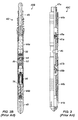
- FIG. 2A A typical gas lift valve 40A used in the art for a wireline-retrievable system is shown in Figure 2A .
- the gas-lift valve 40A has upper and lower seals 44a-b separating vale ports46, which communicate with injection gas ports 48.
- a valve piston 52 is biased closed by a gas charge dome 50 and a bellows 56. At its distal end, the valve piston 52 moves relative to a valve seat 54 at the valve ports 46 in response to pressure on the bellows 56 from the gas charge dome 50.
- a predetermined gas charge applied to the dome 50 and bellows 56 therefore biases the valve piston 52 against the valve seat 54 and close the valve ports46.
- a check valve 58 in the gas-lift valve 40 is positioned downstream from the valve piston 52, valve seat 54, and valve ports 46.
- the check valve 58 keeps flow from the production string (not shown) from going through the injection ports 48 and back into the casing (annulus) through the valve ports 46. Yet, the check valve 58 allows injected gas from the valve ports46 to pass out the gas injection ports 48.
- FIG. 2B An alternative type of gas lift valve 40B is shown in Figure 2B .
- This valve 40B is similar to that disclosed in U.S. Pat. Pub. No. 2010/0096142 , entitled “Gas-Lift Valve and Method of Use.” Briefly, this valve 40B is like an inverted form of the typical gas-lift valve.
- the valve 40B has inlet ports 46 and a valve seat 54. However, the valve's outlet port 43 is disposed at the upper end of the valve 40B as opposed to being at the downhole end.
- a tubular latch 42 at the top of the valve 40B has a removable plug (not shown) that can dispose in the outlet port 43.
- valve 40B has a gas charged dome 50, a valve ball member 52, and a bellows 56 positioned below the valve seat 54, as opposed to disposing in the traditional arrangement above the valve seat.
- the purpose of this inverted gas lift valve 40B is to redirect the injection gas out of the valve's uphole outlet 43 in an upward direction so the injected gas flows along with the natural flow of the tubing string. This upward injection is believed to increase production.
- dummy valves can install in the side pocket of a mandrel. These dummy valves are not actually valves because they merely dispose in the mandrel to seal of the mandrel's ports so pressure testing can be performed.
- a circulating device 40C is another device that can dispose in a mandrel downhole. Similar to an RC-1 DC circulating device available from Weatherford International, the circulating device 40C has inlets 46 at a central portion of the device's housing. Upper and lower outlets 41a-b on the device 40C communicate with these central inlets 46, and packing seals 44a-b disposed about the device 40C isolate the inlets 46 when installed in a mandrel.
- the circulating device 40C lacks loaded valve mechanisms and instead merely has check darts 45a-b and seats 47a-b. Fluids entering the inlets 46 from a borehole annulus can pass the check darts 45a-b and seats 47a-b and can proceed unhindered out the outlets 41 a-b. The check darts 45a-b simply restrict reverse flow from the tubing past the seats 47a-b. Being unloaded, this device 40C is essentially not capable of closing off inlet flow so it cannot be used as an unloading valve of injected gas in a gas lift operation.
- High rate wells typically need high gas volumes for gas lift to work.
- the gas lift system must inject very large volumes of gas so gas lift valves with large injection ports are used. Understandably, the size of the gas lift valve limits the available size for the injection ports so that larger and larger valve sizes are needed to provide the required larger injection ports.
- the size of the production casing and size of the tubing string limits the size of the gas lift valve that can be used.
- valves i.e., a valve having 1-in. OD
- the operator runs a mandrel with multiple pockets or runs two standard mandrels separated by a joint of pipe on the tubing string in the borehole.
- the smaller valves installed in the pockets of the mandrel(s) can provide double the gas passage.
- the multiple valves, pockets, and mandrels significantly complicates servicing the completion.
- the subject matter of the present disclosure is directed to overcoming, or at least reducing the effects of, one or more of the problems set forth above.
- a gas lift valve deploying on a mandrel downhole, the gas lift valve comprising at least one of: a housing having at least one inlet in fluid communication outside the mandrel and having first and second outlets in fluid communication inside the mandrel; a first valve mechanism disposed in the housing and biased to a closed condition restricting fluid communication from the at least one inlet to the first outlet, the first valve mechanism being responsive to fluid pressure at the at least one inlet and controlling passage of inlet fluid from the at least one inlet to the first outlet in response to the fluid pressure; and a second valve mechanism disposed in the housing and biased to a closed condition restricting fluid communication from the at least one inlet to the second outlet, the second valve mechanism being responsive to fluid pressure at the at least one inlet and controlling passage of inlet fluid from the at least one inlet to the second outlet in response to the fluid pressure.
- the valve may further comprise a latch mechanism disposed on the housing, the latch mechanism having a port communicating with the second outlet.
- the latch mechanism may comprise a plug removably disposing in the port.
- the first valve mechanism may comprise: a seat disposed between the at least one inlet and the first outlet; and a valve member biased relative to the seat to restrict fluid communication through the seat.
- the first valve mechanism may further comprise a check valve disposed between the seat and the first outlet, the check valve permitting fluid communication from the seat to the first outlet and restricting fluid communication from the first outlet to the seat.
- the valve member may comprise a bellows separating fluid pressure at the at least one inlet from a pressure in the housing and biasing the valve member relative to the seat.
- the valve member may comprise a spring biasing the valve member relative to the seat.
- the valve member may comprise: a spring biasing the valve member relative to the seat; and a bellows fluid pressure at the at least one inlet from a pressure in the housing and biasing the valve member relative to the seat.
- the housing may define a chamber holding the pressure therein.
- the chamber may hold the pressure for the first and second valve mechanisms.
- the housing may define at least one pressure chamber; and the first and second valve mechanisms may each comprise a bellows separating fluid pressure at the at least one inlet from that at least one pressure chamber and biasing a valve member relative to a seat.
- the housing may comprise: a first seal on the housing engaging the inside of the mandrel and isolating fluid communication outside the housing between the at least one inlet and the first outlet; and a second seal on the housing engaging the inside of the mandrel and isolating fluid communication outside the housing between the at least one inlet and the second outlet.
- the housing may have first and second ends and an intermediate portion, the first end having the first outlet, the second end having the second outlet, the intermediate portion having the at least one inlet.
- the second end may comprise a latch mechanism disposed thereon, the latch mechanism permitting fluid communication from the second outlet therethrough.
- the at least one inlet may comprise a first inlet in fluid communication with the first valve mechanism and a second inlet in fluid communication with the second valve mechanism.
- the valve may further comprise a seal disposed on the housing in between the first and second inlets and engaging the inside of the mandrel.
- the first and second valve mechanisms may operate at similar opening and closing pressures as one another.
- the first and second valve mechanisms may operate at different opening and closing pressures from one another.
- the first and second valve mechanisms may produce different gas injection rates.
- a gas lift valve deploying on a mandrel downhole, the gas lift valve comprising at least one of: a housing having at least one inlet in fluid communication outside the mandrel and having first and second outlets in fluid communication inside the mandrel, the housing defining at least one pressure chamber; a first valve member disposed in the housing and controlling passage of inlet fluid from the at least one inlet through a first seat to the first outlet; a first bellows separating fluid pressure at the at least one inlet from the at least one pressure chamber and biasing the first valve member relative to the first seat; a second valve member disposed in the housing and controlling passage of inlet fluid from the at least one inlet through a second seat to the second outlet; and a second bellows separating fluid pressure at the at least one inlet from the at least one pressure chamber and biasing the second valve member relative to the first seat.
- a gas lift system comprising at least one of: a mandrel deploying downhole; and a gas lift valve disposing in the mandrel, the gas lift valve comprising: a housing having at least one inlet in fluid communication outside the mandrel and having first and second outlets in fluid communication inside the mandrel; a first valve mechanism disposed in the housing and biased to a closed condition restricting fluid communication from the at least one inlet to the first outlet, the first valve mechanism being responsive to fluid pressure at the at least one inlet and controlling passage of inlet fluid from the at least one inlet to the first outlet in response to the fluid pressure; and a second valve mechanism disposed in the housing and biased to a closed condition restricting fluid communication from the at least one inlet to the second outlet, the second valve mechanism being responsive to fluid pressure at the at least one inlet and controlling passage of inlet fluid from the at least one inlet to the second outlet in response to the fluid pressure.
- the mandrel may comprise a side pocket disposed on the inside of the mandrel and holding the gas lift valve therein.
- the mandrel may define at least one port communicating the inside with the outside of the mandrel.
- the at least one port may comprise first and second ports defined in the mandrel, the first valve mechanism controlling passage of inlet fluid from the first port, the second valve mechanism controlling passage of inlet fluid from the second port.
- the at least one inlet may comprise first and second inlets, the first valve mechanism controlling passage of inlet fluid from the first inlet, the second valve mechanism controlling passage of inlet fluid from the second inlet.
- a gas lift method comprising at least one of: deploying a gas lift valve downhole in a mandrel; biasing a first valve mechanism in the gas lift valve to a closed condition restricting fluid communication from at least one inlet to a first outlet of the gas lift valve; basing a second valve mechanism in the gas lift valve to a closed condition restricting fluid communication from the at least one inlet to a second outlet of the gas lift valve; communicating fluid outside the mandrel through the at least one inlet in the gas lift valve; controlling passage of inlet fluid from the at least one inlet to the first outlet by making the first valve mechanism responsive to fluid pressure at the least one inlet; and controlling passage of inlet fluid from the at least one inlet to the second outlet by making the second valve mechanism responsive to fluid pressure at the least one inlet.
- Deploying the gas lift valve downhole on the mandrel may comprise engaging a latch on the gas lift valve in a profile defined in the interior of the mandrel.
- Biasing the first valve mechanism may comprise biasing a first valve member relative to a first seat communicating the at least one inlet with the first outlet.
- Biasing the first valve member relative to the first seat may comprise biasing the first valve member with a spring disposed in the gas lift valve.
- the method may further comprise holding a stored pressure in the gas lift valve, wherein biasing the first valve member relative to the first seat comprises moving the first valve member with a bellows separating inlet pressure from the stored pressure.
- Controlling passage of inlet fluid from the at least one inlet to the first outlet and to the second outlet may comprise biasing the first and second valve mechanism with a same stored pressure in the gas lift valve holding the at least one dome pressure.
- Controlling passage of the inlet fluid from the at least one inlet to the second outlet may comprise removing a plug removably disposed on the second outlet of the gas lift valve.
- a gas lift system disclosed herein has increased gas injection capabilities, but does not require an increased outside diameter for the gas lift valve. In this way, the gas lift system can maintain a minimal mandrel running diameter. This minimal running diameter can make the gas lift system useful for slimhole completions.
- standard completions that require large amounts of injection gas that cannot pass conventional 1 1 ⁇ 2" OD valves will also benefit from the disclosed gas lift system.
- the disclosed gas lift system has mandrels deploying downhole and has gas lift valves disposed on the mandrels.
- the gas lift valve can be a wireline-retrievable gas lift valve that disposes in a side pocket mandrel.
- the gas lift valve can be a tubing retrievable gas lift valve disposed on any conventional mandrel (even a mandrel with an external mount for the gas lift valve).
- the mandrel can have an interior and can have at least one port communicating outside the mandrel.
- the gas lift valve of the present disclosure has multiple injection ports, and a common opening pressure can control the opening of each of the injection ports in the valve.
- the valve can open in two places, allowing gas to flow through the nose of the valve as well as through the top of the valve ( i.e., at a ported latch if present). In this way, the valve can offer larger injection capabilities while keeping a suitable outside diameter.
- the gas lift valve has a housing sealingly deployed in the mandrel's interior.
- chevron or other seals disposed on the outside of the housing can engage against the mandrel.
- the housing has at least one inlet in fluid communication with at least one port in the mandrel that communicates with the annulus of the wellbore. This at least one inlet receives the injected gas entering the mandrel from the annulus through the mandrel's at least one port.
- the housing To inject gas into the mandrel's interior, the housing has first and second outlets in fluid communication with the mandrel's interior.
- a first valve mechanism disposed in the housing controls passage of inlet fluid from the at least one inlet to the first outlet, and a second valve mechanism disposed in the housing controls passage of the inlet fluid from the at least one inlet to the second outlet.
- the valve can have a latch mechanism disposed on the housing, and the latch mechanism can have a port communicating with the valve's second outlet.
- the port can be permanently open or can be plugged and later opened.
- the latch mechanism can have a plug removably disposed in the port for the second outlet, and operators can remove the plug to convert the gas lift valve from single outlet injection to dual outlet injection.
- the plug may be useful in some applications, the removable plug may not be necessary given the implementation and intended operation of the valve.
- the valve mechanisms can include a seat disposed between the valve's inlet and outlet and can include a valve member biased relative to the seat.
- the valve member restricts passage of the inlet fluid through the seat by moving a piston with a bellows subjected to differential pressure between a dome volume pressure and inlet pressure to prevent backflow into the valve, check valves are disposed at each of the outlets restricting fluid communication back into the valve.
- valve members can each have a bellows biasing the valve member relative to the seat.
- the housing defines at least one pressure chamber in fluid communication with these bellows.
- the valve can be spring loaded and not use a dome charge.
- the valve can use a combination of a spring load and a pressure chamber.
- the two valve mechanisms in the valve can operate in tandem or can operate differently to produce different gas injection rates.
- Fig. 1 illustrates a gas lift system according to the prior art.
- Fig. 2A is a cross-section of a gas lift valve according to the prior art.
- Fig. 2B is a cross-section of an inverted style gas lift valve according to the prior art.
- Fig. 3 is a cross-section of a dual flow circulating device according to the prior art.
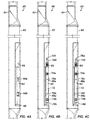
- Fig. 4A shows a mandrel for a gas lift system according to the present disclosure.
- Fig. 4B shows a gas lift valve of the present disclosure deployed in the mandrel.
- Fig. 4C shows the gas lift valve in an operating state in the mandrel.
- Fig. 5 shows a gas lift valve according to the present disclosure in partial cross-section.
- Figs. 6A-6B show the disclosed gas lift valve in more detailed cross-section.
- Fig. 7A shows the disclosed gas lift valve with one arrangement of seals and inlets.
- Fig. 7B shows the disclosed gas lift valve with another arrangement of seals and inlets.
- Fig. 7C shows the disclosed gas lift valve with one inlet for receiving inlet fluid.
- Fig. 8A shows one type of latch mechanism with a removable plug disposed on the end of the disclosed gas lift valve.
- Fig. 8B shows another type of latch mechanism with a removable plug disposed on the end of the disclosed gas lift valve.
- Fig. 9 shows a portion of the housing having a port for filling the chamber.
- Fig. 10 shows a gas lift valve of the present disclosure having two valve mechanisms that use springs and bellows.
- FIG. 4A-4C Portion of a gas lift system according to the present disclosure is shown in Figures 4A-4C during various stages of operation.
- the gas lift system has one or more mandrels 60 and has one or more gas lift valves 70 that dispose downhole on a tubing string (not shown).
- Figures 4A-4C only show one mandrel 60 and one gas lift valve 70, but the gas lift system can have several mandrels 60 and gas lift valves 70 that deploys on a tubing string in the gas lift system not unlike that discussed previously.
- the mandrel 60 and valve 70 can be configured for a wireline-retrievable gas lift system.
- teachings of the present disclosure can apply equally well to a tubing retrievable gas lift system.
- the mandrel 60shown here is a side pocket mandrel having a side pocket 64 in an offset bulge 62.
- a suitable type of mandrel includes a McMurry-Macco ® side pocket mandrel, such as the SM-2 or SFO-2 series available from Weatherford International.
- the mandrel can be any known type of mandrel, including a conventional mandrel with an external mount for a gas lift valve.
- the pocket's upper end has a seating profile 65 for engaging a latch mechanism (100; Fig. 4B ) of a gas lift valve (70; Fig. 4B ) or other tool, while the pocket's other end 68 may be open.
- Ports 66a-b in the mandrel's pocket 64 communicate with the surrounding annulus outside the mandrel 60 and allow for fluid communication during gas lift or other types of operations.
- the mandrel 60 can have dual sets of ports 66a-b as shown for gas in the surrounding annulus to enter the mandrel 60, although a single set of ports or more that two sets could be used.
- a gas lift valve 70 of the present disclosure deploys in the mandrel 60 with its dual ports 66a-b.
- the gas lift valve 70 can be installed manually in the mandrel 60 during initial installation at the surface so that the mandrel 60 with installed gas lift valve 70 can be run downhole together without the need for a slickline operation to install the gas lift valve 70.
- the gas lift valve 70 may typically be lowered down the tubing string to the side pocket mandrel 60 when it is already installed downhole.
- a slickline operation and appropriate tool can be used to run the gas lift valve 70 downhole in the tubing string to install it in the side pocket 64 so the valves seals74a-b can straddle and packoff the mandrel's ports 66a-b.
- the mandrel 60 may also have an orienting sleeve 61 for facilitating the slickline operations and for properly aligning the gas lift valve 70 within the pocket 64.
- a tool discriminator (not shown) can be used to guide the gas lift valve 70 into the pocket 64 and deflects larger tools to prevent damage to the gas lift valve 70.
- the gas lift valve 70 has dual inlet ports 76a-b to receive inlet gas from the mandrel's ports 66a-b. At its downhole end or nose, the gas lift valve 70 has an outlet78b for the injected gas to leave the valve 70and enter the tubing string. At its uphole end, the gas lift valve 70 has an outlet 78a, which can communicate with a port in a latch mechanism100 for engaging in the mandrel's seating profile 65. A number of latch mechanisms100 can be used, as discussed in more detail later. The latch mechanism 100 is ported for the injected gas to leave the valve's outlet78a and enter the tubing string.
- the gas lift valve 70 in an operating state in the mandrel 60 has its outlets 78a-b exposed to the interior of the mandrel 60.
- the downhole outlet 78b allows injected gas to enter the mandrel's interior and coupled tubing string. Gas can also exit the outlet 78a at the latch mechanism 100 and enter the mandrel's interior and coupled tubing string.
- the latch mechanism 100 can define a permanently open port.
- the latch mechanism 100 can have a plug 110 that can be removed from the latch's port once the gas lift valve 70 is deployed and ready for operation.
- a plug 110 that can be removed from the latch's port once the gas lift valve 70 is deployed and ready for operation.
- Operators can use a slickline operation to remove the plug 110 so that the upper outlet 78a of the gas lift valve 70 can be used.
- the plug 110 may be useful in some applications, it is not strictly necessary in other implementations so the valve 70 can lack the plug 110 altogether.
- valve's outlet 78a is exposed to the mandrel's interior, and the valve 70 can operate as described previously to regulate gas flow from the surrounding annulus to the tubing string.
- the gas lift valve 70 installed in the mandrel 60, double the gas injection can be achieved from the borehole annulus into the tubing string.
- valves i.e., valve having 1-in. OD
- the operator may typically runs a mandrel with multiple pockets or run two standard mandrels separated by a joint of pipe on the tubing string in the borehole.
- double the gas passage may result, using the standard valves, pockets, and mandrels significantly complicates servicing the completion.
- the gas lift valve 70 of the present disclosure can provide double the gas passage without complicating the completion.
- the disclosed gas lift valve 70 can have a conventional outer diameter and can install in a conventional mandrel 60 as noted herein.
- the gas lift valve 70 has two valve mechanisms to control the passage of injected gas through the valve 70 and into the tubing string.
- Figure5 shows a gas lift valve 70 in partial cross-section
- Figures6A-6B show the gas lift valve 70 in more detailed cross-sections.
- the valve 70 has an elongated housing 72, which can be composed of several interconnected subassemblies as is customary in the art.
- the housing 72 is cylindrical and can have a diameter comparable to existing gas lift valves.
- the gas lift valve 70 even with such a conventional diameter can offer higher gas injection rates due to the dual outlets 78a-b as discussed herein.
- the gas lift valve 70 has first and second inlets 76a-b for receiving inlet fluid (i.e., injected gas) from the mandrel (60) and has first and second outlets 78a-b for injecting the gas into the mandrel (60) and tubing string. Because the valve 70 installs in a side pocket of a mandrel and may do so with a slickline operation, the top end 77 of the valve 70 can have a latch mechanism (not shown) that affixes thereto. (As discussed herein, the latch mechanism can be ported so the first outlet 78a can inject gas out of the valve 70.)
- a first seal or packing 74a disposed on the housing 72 engages the mandrel (60) and isolates fluid communication outside the housing 72 between the first inlet 76a and the first outlet 78a.
- a second seal or packing 74b disposed on the housing72 also engages the mandrel (60) and isolates fluid communication outside the housing 72between the second inlet 76b and the second outlet 78b.
- seals 72a-b could be used, such as the chevron seals shown.
- valves inlets 76a-b could communicate directly with the annulus.
- the valve's nose having the outlet 78b would typically thread into a collar on the mandrel (or thread into a check valve threaded into the mandrel's collar).
- the valve's other end with its outlet 78a would need to couple with another collar, check valve, or opening in the conventional mandrel as one skilled in the art would appreciate so the other outlet 78a could communicate with the mandrel's interior.
- the valve 70 has first and second valve mechanisms 80a-b disposed in the housing 70 to control passage of inlet gas from the inlets 76a-b to the outlets 78a-b respectively.
- Each valve mechanism 80a-b has a seat 84a-b disposed between the respective inlet 86a-b and outlet 88a-b and has a valve member 82a-b biased relative to the seat 84a-bto restrict passage of the inlet fluid through the seat 84a-b.
- Each valve mechanism 80a-b also has a check valve 88a-b disposed between the seat 84a-b and the outlet 78a-b. In use, the check valve 88a-b permits fluid communication from the seat 84a-b to the outlet 78a-b and restricts fluid communication in the reverse direction.
- the gas lift valve 70 has bellows 86a-b that convert pressure into movement of the valve members 82a-b. This allows the injected compressed gas to act upon the bellows 86a-b to open the valve 70 and pass into the production fluid fed in from the well's producing zone. As differential pressure is reduced on the bellows 86a-b, the valve members 82a-b can close against the seats 84a-b.
- the valve 70 uses an internal gas charge, usually nitrogen, in a volume dome to provide the closing force for the valve 70.
- the valve 70 can use non-gas charged, atmospheric bellows 86a-b and can use springs to close the valve mechanisms 80a-b.In both configurations, pressure differential on the bellows 86a-b from the injected high-pressure gas opens the valve mechanisms 80a-b.
- the housing72 defines a pressure chamber 90communicating with both of the bellows 86a-b.
- Pressurized gas such as nitrogen, fills the chamber 90 using a port (not shown) that is plugged after filling.
- a port not shown
- the dome pressure held in the pressure chamber 90 acts against both bellows 86a-b of the valve mechanisms 80a-b.
- one end of the bellows 86a-b affixes to the housing near the chamber 90, while the other end affixes to the valve members 82a-b.
- the bellows 86a-b each dispose on stems 83a-b affixed at proximal ends to the housing near the chamber 90, and the valve members 82a-b can reciprocate on the stems' distal ends relative to the seats 84a-b.
- Dome pressure in the chamber 90 can communicate with the inside of the bellows 86a-b via communication ports 87a-b in the stems 83a-b.
- the outsides of the bellows 86a-b are exposed to the inlet pressure from the inlets 76a-b.
- An appropriate amount of oil such as silicon oil, can also partially fill the chamber 90.
- the oil is intended to cover portion of the bellows' inside surfaces and protect the bellows 86a-b from internal-injection pressure.
- the oil can also prevent valve chatter due to any non-uniform injection flow or pressure. Gravity may tend to collect the oil from the chamber 90 more inside the lower bellows 86b. However, at least some oil can be trapped inside the upper bellows 86a even by gravity in the space around the stem 83a as long as the location of the communication ports 87a is disposed further towards the stem 83a's distal end.
- Other solutions available in the art could also be used.
- the valve 70 can have separate pressure chambers (not shown), with each having dome volume communicating with one of the bellows 86a-b.
- the separate chambers can be set to the same or different operating pressures depending on the implementation and the desired operation of the valve 70.
- valve mechanisms 80a-b may be configured to operate similar to one another, meaning that the valve mechanisms 80a-b may operate the same way under given operating conditions.
- the valve mechanisms 80a-b may essentially operate in tandem and respond similarly to the same operating pressures and may produce roughly the same gas injection rates for the outlets 78a-b.
- the bellows 86a-b may be the same, and the inlets 72a-b may be the same size.
- the valve seats 84a-b and other components can be similarly configured.
- the two valve mechanisms 80a-b may be configured to operate different from one another.
- the valve mechanisms 80a-b may respond differently to the same operating pressures and/or may produce different gas injection rates for the outlets 78a-b.
- the bellows 86a-b may react differently to pressure, being of different sizes or the like.
- the inlets 72a-b and the valve seats 84a-b may be of different sizes.
- two separate chambers can be used with each having different dome pressures.
- One or more of these elements may be different between the two valve mechanisms 80a-b so that they are configured to operate differently. This difference in operation may have advantages for some implementations in which different gas inject rates can be used to produce different gas lift results.
- the gas lift valve 70 can have different external seal and port arrangements.
- the gas lift valve 70 as shown in Figure7A has an arrangement of seals 74a-b with one seal 74a on the uphole end and another seal74b on the downhole end.
- the seals 74a-b isolate the dual inlets76a-b on the gas lift valve 70 from the uphole and downhole ends of the side pocket in the mandrel.
- the seals 74a-b can be chevron seals as shown, although other types of suitable seals could be used.
- an intermediate seal 74c can be disposed about the valve 70 in between the inlet ports 76a-b to isolate fluid communication of the mandrel's inlets76a-b from one another once the valve 70 is disposed in the side pocket mandrel.
- This arrangement may allow the dual gas lift valve 70 to be operated more effectively as either a single injection valve or a dual injection valve.
- the plug 110 on the latch mechanism 100 may be left in place after the valve 70 is deployed in the side pocket mandrel. In this way, injected gas would only pass through the downhole inlet 76b and outlet 78b for gas injection.
- the gas lift valve 70 Being able to selectively make the gas lift valve 70 operate with either single injection or dual injection can have a number of advantages for a given implementation.
- one or more of the gas lift valves 70 may be deployed for single injection operation, and at some later point, operators may convert them for dual injection operation depending on the circumstances.
- a gas lift system may be deployed with gas lift valves configured for single and dual flow operation down the tubing string to meet a particular production need.
- the gas lift valve of the present disclosure can have one inlet for both valve mechanisms 80a-c.
- Figure 7C shows the disclosed gas lift valve 70 with one inlet 76c for receiving inlet fluid. With proper routing for fluid communication in the valve's housing 72, the one inlet 76c communicating with both valve mechanisms (80a-b) inside the valve 70. To do this, passages and spaces (not shown) in the housing 72 around the outside of the inner components of the valve 70 of Figure 5 can convey inlet fluid from the one inlet 76c to the valve mechanisms (80a-b) inside the valve 70.
- valve 70 can have a pair of seals 74a-b disposed thereon to isolate the one inlet 76c from the mandrel (60) when deployed therein.
- the mandrel (60) may also have a single port or set of ports (66) communicating with the annulus.
- the gas lift valve 70 has a latch mechanism 100used to deploy the valve in the side pocket (64) of the mandrel (60).
- the latch mechanism 100 can have a permanently open port or may have a plug removably disposed in the port.
- One type of latch mechanism 100a shown in Figure 8A is a ring-style latch used to install and retrieve the valve 70 in a side pocket mandrel, while another type of latch mechanism 100b in Figure 8B is a collet-type latch.
- the latch mechanism 100aof Figure 8A has ring-style locking mechanism with a central core 120 attached by a coupling member 128to the threaded end 77 of the gas lift valve's housing 72.
- a sleeve 124 movable on the core 120 is biased by a spring 125.
- the sleeve 124's lower end can move relative to a ring 126 allowing the ring 126 to engage or disengage from a complementary lock profile of a side pocket mandrel.
- a shear pin 123 initially holds the sleeve 124 in position on the central core 120.
- a plug 110 For closing off the outlet 78a on the gas lift valve, a plug 110can dispose in an internal passage 122 of the central core 120.
- the plug 110 uses a shear pin 112 and O-rings 114 as a temporary connection to seal the valve's outlet 78a. In some installations, however, such a plug 110 may not be used so that the latch mechanism 100a can remain permanently opened.
- the collet-type latch mechanism 100b of Figure 8B attaches to the threaded end 77 of the valve's housing72.
- the latch mechanism 100 buses a collet-type locking mechanism similar to a MT-2 style latch used for installing slickline retrievable valves in side pocket mandrels.
- the latch mechanism 100b can lock in a 360-degree latch-pocket profile of a mandrel ( See e.g., profile 65 in Fig. 4A ).
- the latch mechanism 100b has a collet 132, a latch housing 136, a latch sleeve 138, and a central core 140.
- the collet 132 is movably positioned on the sleeve 138, and the sleeve 138 is movably positioned on the central core 140.
- the central core 140 affixes inside the latch housing 136, and the latch housing 136 affixes to the valve's distal end 77.
- Biased latch lugs 134 on the collet 132 can move within slots 137 in the latch housing 136.
- Manipulation of the latch sleeve 138 changes its position along the central core 140 and either permits or restricts the extension or bending of the biased lugs 134 in the slots 137.
- the lugs 134 can catch on an appropriate latch-pocket profile (65) of a side pocket mandrel (60) (See e.g. , Fig. 4A ) to hold the valve 70 in place.
- a plug 110 can dispose in an internal passage 142 of the central core 140.
- the plug 100 uses a shear pin 126 and O-rings 127 as a temporary connection to seal the valve's outlet 78a. In some installations, however, such a plug 110 may not be used so that the latch mechanism 100b can remain permanently opened.
- the chamber 90 of the gas lift valve 70 is filled with a pressure charge, typically nitrogen.
- a core valve is used to fill a pressure dome in a gas lift valve.
- Such a core valve is typically used at the top end of the valve where the pressure dome is usually located.
- the port for filling the chamber 90 is modified from the typical arrangement. As shown in Figure 9 , for example, a recess 79 in the housing 72 defines a port 92 communicating with the chamber 90.
- a core valve 94 installs in this port 92, and a plug 96 threads in the port 92 behind the core valve 94 for additional sealing.
- the core valve 94 can be up to 1 ⁇ 2-inch in length so the port 94 may be angled to better fit the valve's diameter.
- Other port mechanisms and check valve for filing the chamber with pressurized gas and subsequent sealing could also be used, as will be appreciated with the benefit of the present disclosure.
- valve mechanisms 80a-b use bellows to operate.
- the gas lift valve 70 of Figure 10 uses bellows 86a-band springs 98a-bto operate the two valve mechanisms 80a-b.
- similar reference numerals are used for similar components to those associated with the valve disclosed above.
- the valve 70 has the elongated housing 72 having external packings 74a-b for engaging the mandrel, inlets 76a-b for receiving inlet fluid, and outlets 78a-b for injecting the gas.
- the top end 77 can have a latch mechanism (not shown) that affixes thereto.
- valve 70 has valve mechanisms 80a-b to control passage of inlet gas from the inlets 76a-b to the outlets 78a-b respectively.
- Each valve mechanism 80a-b has a seat 84a-b disposed between the respective inlet 86a-b and outlet 88a-b and has a valve member 82a-b biased relative to the seat 84a-b to restrict passage of the inlet fluid through the seat 84a-b.
- Each valve mechanism 80a-b also has a check valve 88a-b disposed between the seat 84a-b and the outlet 78a-b.
- the gas lift valve 70 has bellows 86a-b and springs 98a-b to operate the valve mechanisms 80a-b.
- the bellows 86a-b are non-gas charged, atmospheric bellows separating inlet pressure at the inlets 76a-b from atmospheric chambers 90a-b in which the springs 98a-b dispose.
- Intermediate elements 91 disposed in the valve 70 isolate the chambers 90a-b from one another. If desired, fluid communication between the chambers 90a-b could be provided through a flow channel (not shown) in the elements 91.
- valve 70 of Figure 10 may operate using the springs 98a-b without the bellows 86a-b. This would merely require modifying the valve 70 of Figure 10 to exclude those features associated with the bellows 86a-b. In this way, only the springs 98a-b would be intended to operate the valve mechanisms 80a-b of the valve 70.
- valve 70 of Figure 10 may use a mixed combination of spring and gas-charged bellows to operate the valve mechanisms 80a-b and control passage of inlet gas from the inlets 76a-b to the outlets 78a-b, respectively.
- the lower valve mechanism 80b may use a bellows 86b and a gas charged dome in chamber 90b without a spring (98b) in an arrangement similar to the mechanism 80b discussed previously with reference to Figure 6B .
- the upper valve mechanism 80a may use a spring 98a and non-gas charged bellows 86a in an arrangement similar to the mechanism discussed above with reference to Figure 10 .
- only the spring 98a could be used without the bellows 86a.
- the valve could also reverse arrangements of these mixed types of mechanisms 80a-b.
- a gas lift system has mandrels deploying downhole and has gas lift valves deploying on the mandrels.
- the mandrel can have an interior and can have at least one port communicating outside the mandrel.
- the gas lift valve of the present disclosure has multiple injection outlets, and a common opening pressure can control the opening of each of the injection outlets in the valve.
- the valve can open in two places, allowing gas to flow through the nose of the valve as well as through a ported latch at the top of the valve. In this way, that valve can offer larger injection capabilities while keeping a suitable outside diameter.
Landscapes
- Geology (AREA)
- Life Sciences & Earth Sciences (AREA)
- Engineering & Computer Science (AREA)
- Mining & Mineral Resources (AREA)
- Environmental & Geological Engineering (AREA)
- Fluid Mechanics (AREA)
- Physics & Mathematics (AREA)
- General Life Sciences & Earth Sciences (AREA)
- Geochemistry & Mineralogy (AREA)
- Details Of Valves (AREA)
- Check Valves (AREA)
- Filling Or Discharging Of Gas Storage Vessels (AREA)
- Lift Valve (AREA)
Abstract
Description
- To obtain hydrocarbon fluids from an earth formation, a wellbore is drilled into an area of interest within a formation. The wellbore may then be "completed" by inserting casing in the wellbore and setting the casing using cement. Alternatively, the wellbore may remain uncased as an "open hole," or it may be only partially cased. Regardless of the form of the wellbore, production tubing is run into the wellbore to convey production fluid (e.g., hydrocarbon fluid, which may also include water) to the surface.
- Often, pressure within the wellbore is insufficient to cause the production fluid to naturally rise through the production tubing to the surface. In these cases, an artificial lift system can be used to carry the production fluid to the surface. One type of artificial lift is a gas lift system, of which there are two primary types: tubing-retrievable gas lift systems and wireline-retrievable gas lift systems. Each type of gas lift system uses several gas lift valves spaced along the production tubing. The gas lift valves allow gas to flow from the annulus into the production tubing so the gas can lift production fluid in the production tubing. Yet, the gas lift valves prevent fluid to flow from the production tubing into the annulus.
- In gas lift, high-pressure gas is injected into the production conduit of the well in a continuous fashion to reduce the backpressure on the formation by reducing the hydrostatic load of the production fluid. Gas lift can also be used in a cyclic manner to displace well fluid to the surface by displacing a fluid slug with an expanding high-pressure gas bubble that lifts the slug to the surface. A major component in a gas lift system is the gas lift valve. The gas lift valve is used to communicate the injection gas form the annulus into the tubing string. Various types of gas lift valves exist to meet various operating parameters of the well.
- A typical wireline-retrievable
gas lift system 10 is shown inFigure 1 . Operators inject compressed gas G into theannulus 22 between aproduction tubing string 20 and thecasing 24 within acased wellbore 26. Avalve system 12 supplies the injection gas G from the surface and allows produced fluid to exit thegas lift system 10. -
Side pocket mandrels 30 spaced along theproduction string 20 holdgas lift valves 40 withinside pockets 32. As noted previously, thegas lift valves 40 are one-way valves that allow gas flow from theannulus 22 into theproduction string 20 and prevent gas flow from theproduction string 20 into theannulus 22. - In operation, the production fluid P flows from the formation into the
wellbore 26 throughcasing perforations 28 and then flows into theproduction tubing string 20. Aproduction packer 14 located on theproduction string 20 forces the flow of production fluid P from a formation up through theproduction string 20 instead of up through theannulus 22. When it is desired to lift the production fluid P, compressed gas G is introduced into theannulus 22. The production packer 14 forces the gas flow from theannulus 22 into theproduction string 20 through thegas lift valves 40. In particular, the gas G enters from theannulus 22 throughports 34 in the mandrel'sside pockets 32. Disposed inside theside pockets 32, thegas lift valves 40 then control the flow of injected gas I into theproduction string 20. As the injected gas I rises to the surface, it helps to lift the production fluid P up theproduction string 20 to the surface. - A typical
gas lift valve 40A used in the art for a wireline-retrievable system is shown inFigure 2A . The gas-lift valve 40A has upper andlower seals 44a-b separating vale ports46, which communicate withinjection gas ports 48. Avalve piston 52 is biased closed by agas charge dome 50 and abellows 56. At its distal end, thevalve piston 52 moves relative to avalve seat 54 at thevalve ports 46 in response to pressure on thebellows 56 from thegas charge dome 50. A predetermined gas charge applied to thedome 50 andbellows 56 therefore biases thevalve piston 52 against thevalve seat 54 and close the valve ports46. - A
check valve 58 in the gas-lift valve 40 is positioned downstream from thevalve piston 52,valve seat 54, andvalve ports 46. Thecheck valve 58 keeps flow from the production string (not shown) from going through theinjection ports 48 and back into the casing (annulus) through thevalve ports 46. Yet, thecheck valve 58 allows injected gas from the valve ports46 to pass out thegas injection ports 48. - An alternative type of
gas lift valve 40B is shown inFigure 2B . Thisvalve 40B is similar to that disclosed inU.S. Pat. Pub. No. 2010/0096142 , entitled "Gas-Lift Valve and Method of Use." Briefly, thisvalve 40B is like an inverted form of the typical gas-lift valve. Thevalve 40B hasinlet ports 46 and avalve seat 54. However, the valve'soutlet port 43 is disposed at the upper end of thevalve 40B as opposed to being at the downhole end. Atubular latch 42 at the top of the valve 40Bhas a removable plug (not shown) that can dispose in theoutlet port 43. - Internally, the
valve 40B has a gas chargeddome 50, avalve ball member 52, and abellows 56 positioned below thevalve seat 54, as opposed to disposing in the traditional arrangement above the valve seat. The purpose of this invertedgas lift valve 40B is to redirect the injection gas out of the valve'suphole outlet 43 in an upward direction so the injected gas flows along with the natural flow of the tubing string. This upward injection is believed to increase production. - Other types of downhole devices, which are not gas lift valves, can install in side pocket mandrels. For example, "dummy" valves can install in the side pocket of a mandrel. These dummy valves are not actually valves because they merely dispose in the mandrel to seal of the mandrel's ports so pressure testing can be performed.
- As shown in
Figure 3 , a circulatingdevice 40C is another device that can dispose in a mandrel downhole. Similar to an RC-1 DC circulating device available from Weatherford International, the circulatingdevice 40C hasinlets 46 at a central portion of the device's housing. Upper andlower outlets 41a-b on thedevice 40C communicate with thesecentral inlets 46, and packingseals 44a-b disposed about thedevice 40C isolate theinlets 46 when installed in a mandrel. - Internally, the circulating
device 40C lacks loaded valve mechanisms and instead merely has checkdarts 45a-b andseats 47a-b. Fluids entering theinlets 46 from a borehole annulus can pass thecheck darts 45a-b andseats 47a-b and can proceed unhindered out the outlets 41 a-b. Thecheck darts 45a-b simply restrict reverse flow from the tubing past theseats 47a-b. Being unloaded, thisdevice 40C is essentially not capable of closing off inlet flow so it cannot be used as an unloading valve of injected gas in a gas lift operation. - High rate wells typically need high gas volumes for gas lift to work. To meet this need, the gas lift system must inject very large volumes of gas so gas lift valves with large injection ports are used. Understandably, the size of the gas lift valve limits the available size for the injection ports so that larger and larger valve sizes are needed to provide the required larger injection ports. Ultimately, the size of the production casing and size of the tubing string limits the size of the gas lift valve that can be used.
- As an additional problem, high rate wells require large tubing sizes to produce efficiently. The increased tubing size reduces the amount of available room between the production casing and tubing string and limits the size of the gas lift valves that can be installed. In fact, gas lift valves that can meet large injection volumes are being manufactured that prove difficult to fit into the completion.
- In some situations in a high rate well, an operator has to run smaller valves (i.e., a valve having 1-in. OD) downhole because of the casing clearance in the borehole. To improve gas injection, the operator runs a mandrel with multiple pockets or runs two standard mandrels separated by a joint of pipe on the tubing string in the borehole. In this way, the smaller valves installed in the pockets of the mandrel(s) can provide double the gas passage. As expected, the multiple valves, pockets, and mandrels significantly complicates servicing the completion.
- The subject matter of the present disclosure is directed to overcoming, or at least reducing the effects of, one or more of the problems set forth above.
- According to a first aspect of the present invention, there is provided a gas lift valve deploying on a mandrel downhole, the gas lift valve comprising at least one of: a housing having at least one inlet in fluid communication outside the mandrel and having first and second outlets in fluid communication inside the mandrel; a first valve mechanism disposed in the housing and biased to a closed condition restricting fluid communication from the at least one inlet to the first outlet, the first valve mechanism being responsive to fluid pressure at the at least one inlet and controlling passage of inlet fluid from the at least one inlet to the first outlet in response to the fluid pressure; and a second valve mechanism disposed in the housing and biased to a closed condition restricting fluid communication from the at least one inlet to the second outlet, the second valve mechanism being responsive to fluid pressure at the at least one inlet and controlling passage of inlet fluid from the at least one inlet to the second outlet in response to the fluid pressure.
- The valve may further comprise a latch mechanism disposed on the housing, the latch mechanism having a port communicating with the second outlet.
- The latch mechanism may comprise a plug removably disposing in the port.
- The first valve mechanism may comprise: a seat disposed between the at least one inlet and the first outlet; and a valve member biased relative to the seat to restrict fluid communication through the seat.
- The first valve mechanism may further comprise a check valve disposed between the seat and the first outlet, the check valve permitting fluid communication from the seat to the first outlet and restricting fluid communication from the first outlet to the seat.
- The valve member may comprise a bellows separating fluid pressure at the at least one inlet from a pressure in the housing and biasing the valve member relative to the seat.
- The valve member may comprise a spring biasing the valve member relative to the seat.
- The valve member may comprise: a spring biasing the valve member relative to the seat; and a bellows fluid pressure at the at least one inlet from a pressure in the housing and biasing the valve member relative to the seat.
- The housing may define a chamber holding the pressure therein.
- The chamber may hold the pressure for the first and second valve mechanisms.
- The housing may define at least one pressure chamber; and the first and second valve mechanisms may each comprise a bellows separating fluid pressure at the at least one inlet from that at least one pressure chamber and biasing a valve member relative to a seat.
- The housing may comprise: a first seal on the housing engaging the inside of the mandrel and isolating fluid communication outside the housing between the at least one inlet and the first outlet; and a second seal on the housing engaging the inside of the mandrel and isolating fluid communication outside the housing between the at least one inlet and the second outlet.
- The housing may have first and second ends and an intermediate portion, the first end having the first outlet, the second end having the second outlet, the intermediate portion having the at least one inlet.
- The second end may comprise a latch mechanism disposed thereon, the latch mechanism permitting fluid communication from the second outlet therethrough.
- The at least one inlet may comprise a first inlet in fluid communication with the first valve mechanism and a second inlet in fluid communication with the second valve mechanism.
- The valve may further comprise a seal disposed on the housing in between the first and second inlets and engaging the inside of the mandrel.
- The first and second valve mechanisms may operate at similar opening and closing pressures as one another.
- The first and second valve mechanisms may operate at different opening and closing pressures from one another.
- The first and second valve mechanisms may produce different gas injection rates.
- According to a further aspect of the present invention, there is provided a gas lift valve deploying on a mandrel downhole, the gas lift valve comprising at least one of: a housing having at least one inlet in fluid communication outside the mandrel and having first and second outlets in fluid communication inside the mandrel, the housing defining at least one pressure chamber; a first valve member disposed in the housing and controlling passage of inlet fluid from the at least one inlet through a first seat to the first outlet; a first bellows separating fluid pressure at the at least one inlet from the at least one pressure chamber and biasing the first valve member relative to the first seat; a second valve member disposed in the housing and controlling passage of inlet fluid from the at least one inlet through a second seat to the second outlet; and a second bellows separating fluid pressure at the at least one inlet from the at least one pressure chamber and biasing the second valve member relative to the first seat.
- According to a further aspect of the present invention, there is provided a gas lift system, comprising at least one of: a mandrel deploying downhole; and a gas lift valve disposing in the mandrel, the gas lift valve comprising: a housing having at least one inlet in fluid communication outside the mandrel and having first and second outlets in fluid communication inside the mandrel; a first valve mechanism disposed in the housing and biased to a closed condition restricting fluid communication from the at least one inlet to the first outlet, the first valve mechanism being responsive to fluid pressure at the at least one inlet and controlling passage of inlet fluid from the at least one inlet to the first outlet in response to the fluid pressure; and a second valve mechanism disposed in the housing and biased to a closed condition restricting fluid communication from the at least one inlet to the second outlet, the second valve mechanism being responsive to fluid pressure at the at least one inlet and controlling passage of inlet fluid from the at least one inlet to the second outlet in response to the fluid pressure.
- The mandrel may comprise a side pocket disposed on the inside of the mandrel and holding the gas lift valve therein.
- The mandrel may define at least one port communicating the inside with the outside of the mandrel.
- The at least one port may comprise first and second ports defined in the mandrel, the first valve mechanism controlling passage of inlet fluid from the first port, the second valve mechanism controlling passage of inlet fluid from the second port.
- The at least one inlet may comprise first and second inlets, the first valve mechanism controlling passage of inlet fluid from the first inlet, the second valve mechanism controlling passage of inlet fluid from the second inlet.
- According to a further aspect of the present invention, there is provided a gas lift method, comprising at least one of: deploying a gas lift valve downhole in a mandrel; biasing a first valve mechanism in the gas lift valve to a closed condition restricting fluid communication from at least one inlet to a first outlet of the gas lift valve; basing a second valve mechanism in the gas lift valve to a closed condition restricting fluid communication from the at least one inlet to a second outlet of the gas lift valve; communicating fluid outside the mandrel through the at least one inlet in the gas lift valve; controlling passage of inlet fluid from the at least one inlet to the first outlet by making the first valve mechanism responsive to fluid pressure at the least one inlet; and controlling passage of inlet fluid from the at least one inlet to the second outlet by making the second valve mechanism responsive to fluid pressure at the least one inlet.
- Deploying the gas lift valve downhole on the mandrel may comprise engaging a latch on the gas lift valve in a profile defined in the interior of the mandrel.
- Biasing the first valve mechanism may comprise biasing a first valve member relative to a first seat communicating the at least one inlet with the first outlet.
- Biasing the first valve member relative to the first seat may comprise biasing the first valve member with a spring disposed in the gas lift valve.
- The method may further comprise holding a stored pressure in the gas lift valve, wherein biasing the first valve member relative to the first seat comprises moving the first valve member with a bellows separating inlet pressure from the stored pressure.
- Controlling passage of inlet fluid from the at least one inlet to the first outlet and to the second outlet may comprise biasing the first and second valve mechanism with a same stored pressure in the gas lift valve holding the at least one dome pressure.
- Controlling passage of the inlet fluid from the at least one inlet to the second outlet may comprise removing a plug removably disposed on the second outlet of the gas lift valve.
- As noted previously, high rate wells need high gas volumes for gas lift to work and also require large tubing sizes to produce efficiently. A gas lift system disclosed herein has increased gas injection capabilities, but does not require an increased outside diameter for the gas lift valve. In this way, the gas lift system can maintain a minimal mandrel running diameter. This minimal running diameter can make the gas lift system useful for slimhole completions. However, standard completions that require large amounts of injection gas that cannot pass conventional 1 ½" OD valves will also benefit from the disclosed gas lift system.
- The disclosed gas lift system has mandrels deploying downhole and has gas lift valves disposed on the mandrels. The gas lift valve can be a wireline-retrievable gas lift valve that disposes in a side pocket mandrel. Alternatively, the gas lift valve can be a tubing retrievable gas lift valve disposed on any conventional mandrel (even a mandrel with an external mount for the gas lift valve).
- In general, the mandrel can have an interior and can have at least one port communicating outside the mandrel. To achieve higher gas injection while maintaining component sizes in desirable ranges, the gas lift valve of the present disclosure has multiple injection ports, and a common opening pressure can control the opening of each of the injection ports in the valve. The valve can open in two places, allowing gas to flow through the nose of the valve as well as through the top of the valve (i.e., at a ported latch if present). In this way, the valve can offer larger injection capabilities while keeping a suitable outside diameter.
- In particular, the gas lift valve has a housing sealingly deployed in the mandrel's interior. For example, chevron or other seals disposed on the outside of the housing can engage against the mandrel. The housing has at least one inlet in fluid communication with at least one port in the mandrel that communicates with the annulus of the wellbore. This at least one inlet receives the injected gas entering the mandrel from the annulus through the mandrel's at least one port.
- To inject gas into the mandrel's interior, the housing has first and second outlets in fluid communication with the mandrel's interior. A first valve mechanism disposed in the housing controls passage of inlet fluid from the at least one inlet to the first outlet, and a second valve mechanism disposed in the housing controls passage of the inlet fluid from the at least one inlet to the second outlet.
- When wireline retrievable, the valve can have a latch mechanism disposed on the housing, and the latch mechanism can have a port communicating with the valve's second outlet. The port can be permanently open or can be plugged and later opened. For example, the latch mechanism can have a plug removably disposed in the port for the second outlet, and operators can remove the plug to convert the gas lift valve from single outlet injection to dual outlet injection. Although the plug may be useful in some applications, the removable plug may not be necessary given the implementation and intended operation of the valve.
- The valve mechanisms can include a seat disposed between the valve's inlet and outlet and can include a valve member biased relative to the seat. The valve member restricts passage of the inlet fluid through the seat by moving a piston with a bellows subjected to differential pressure between a dome volume pressure and inlet pressure to prevent backflow into the valve, check valves are disposed at each of the outlets restricting fluid communication back into the valve.
- As noted above, the valve members can each have a bellows biasing the valve member relative to the seat. The housing defines at least one pressure chamber in fluid communication with these bellows. As an alternative to the pressure chamber, the valve can be spring loaded and not use a dome charge. Moreover, the valve can use a combination of a spring load and a pressure chamber. Depending on the desired configuration, the two valve mechanisms in the valve can operate in tandem or can operate differently to produce different gas injection rates.
- The foregoing summary is not intended to summarize each potential embodiment or every aspect of the present disclosure.
-
Fig. 1 illustrates a gas lift system according to the prior art. -
Fig. 2A is a cross-section of a gas lift valve according to the prior art. -
Fig. 2B is a cross-section of an inverted style gas lift valve according to the prior art. -
Fig. 3 is a cross-section of a dual flow circulating device according to the prior art. -
Fig. 4A shows a mandrel for a gas lift system according to the present disclosure. -
Fig. 4B shows a gas lift valve of the present disclosure deployed in the mandrel. -
Fig. 4C shows the gas lift valve in an operating state in the mandrel. -
Fig. 5 shows a gas lift valve according to the present disclosure in partial cross-section. -
Figs. 6A-6B show the disclosed gas lift valve in more detailed cross-section. -
Fig. 7A shows the disclosed gas lift valve with one arrangement of seals and inlets. -
Fig. 7B shows the disclosed gas lift valve with another arrangement of seals and inlets. -
Fig. 7C shows the disclosed gas lift valve with one inlet for receiving inlet fluid. -
Fig. 8A shows one type of latch mechanism with a removable plug disposed on the end of the disclosed gas lift valve. -
Fig. 8B shows another type of latch mechanism with a removable plug disposed on the end of the disclosed gas lift valve. -
Fig. 9 shows a portion of the housing having a port for filling the chamber. -
Fig. 10 shows a gas lift valve of the present disclosure having two valve mechanisms that use springs and bellows. - Portion of a gas lift system according to the present disclosure is shown in
Figures 4A-4C during various stages of operation. In general, the gas lift system has one ormore mandrels 60 and has one or moregas lift valves 70 that dispose downhole on a tubing string (not shown).Figures 4A-4C only show onemandrel 60 and onegas lift valve 70, but the gas lift system can haveseveral mandrels 60 andgas lift valves 70 that deploys on a tubing string in the gas lift system not unlike that discussed previously. As shown, themandrel 60 andvalve 70 can be configured for a wireline-retrievable gas lift system. However, the teachings of the present disclosure can apply equally well to a tubing retrievable gas lift system. - The mandrel 60shown here is a side pocket mandrel having a
side pocket 64 in an offsetbulge 62. A suitable type of mandrel includes a McMurry-Macco® side pocket mandrel, such as the SM-2 or SFO-2 series available from Weatherford International. Depending on the type of system, however, the mandrel can be any known type of mandrel, including a conventional mandrel with an external mount for a gas lift valve. - The pocket's upper end has a
seating profile 65 for engaging a latch mechanism (100;Fig. 4B ) of a gas lift valve (70;Fig. 4B ) or other tool, while the pocket'sother end 68 may be open.Ports 66a-b in the mandrel'spocket 64 communicate with the surrounding annulus outside themandrel 60 and allow for fluid communication during gas lift or other types of operations. In contrast to the conventional arrangement, themandrel 60 can have dual sets ofports 66a-b as shown for gas in the surrounding annulus to enter themandrel 60, although a single set of ports or more that two sets could be used. - As shown in
Figure 4B , agas lift valve 70 of the present disclosure deploys in themandrel 60 with itsdual ports 66a-b. Thegas lift valve 70 can be installed manually in themandrel 60 during initial installation at the surface so that themandrel 60 with installedgas lift valve 70 can be run downhole together without the need for a slickline operation to install thegas lift valve 70. However, thegas lift valve 70 may typically be lowered down the tubing string to theside pocket mandrel 60 when it is already installed downhole. - For example, a slickline operation and appropriate tool (not shown) can be used to run the
gas lift valve 70 downhole in the tubing string to install it in theside pocket 64 so the valves seals74a-b can straddle and packoff the mandrel'sports 66a-b. Themandrel 60 may also have an orientingsleeve 61 for facilitating the slickline operations and for properly aligning thegas lift valve 70 within thepocket 64. During installation, a tool discriminator (not shown) can be used to guide thegas lift valve 70 into thepocket 64 and deflects larger tools to prevent damage to thegas lift valve 70. - Shown installed in
Figure 4B , thegas lift valve 70 hasdual inlet ports 76a-b to receive inlet gas from the mandrel'sports 66a-b. At its downhole end or nose, thegas lift valve 70 has an outlet78b for the injected gas to leave the valve 70and enter the tubing string. At its uphole end, thegas lift valve 70 has anoutlet 78a, which can communicate with a port in a latch mechanism100 for engaging in the mandrel'sseating profile 65. A number of latch mechanisms100 can be used, as discussed in more detail later. Thelatch mechanism 100 is ported for the injected gas to leave the valve's outlet78a and enter the tubing string. - As best shown in
Figure4C , thegas lift valve 70 in an operating state in themandrel 60 has itsoutlets 78a-b exposed to the interior of themandrel 60. Thedownhole outlet 78b allows injected gas to enter the mandrel's interior and coupled tubing string. Gas can also exit theoutlet 78a at thelatch mechanism 100 and enter the mandrel's interior and coupled tubing string. To do this, thelatch mechanism 100 can define a permanently open port. - Alternatively, the
latch mechanism 100 can have aplug 110 that can be removed from the latch's port once thegas lift valve 70 is deployed and ready for operation. (Details oflatch mechanisms 100 with removable plugs are provided below with reference toFigures 8A-8B .) Operators can use a slickline operation to remove theplug 110 so that theupper outlet 78a of thegas lift valve 70 can be used. Although theplug 110 may be useful in some applications, it is not strictly necessary in other implementations so thevalve 70 can lack theplug 110 altogether. - As shown in
Figure 4C , for example, operators have removed theplug 110 by pulling on theplug 110 and breaking its connection to thelatch mechanism 100 using a slickline operation and appropriate tool. With theplug 110 removed, the valve'soutlet 78a is exposed to the mandrel's interior, and thevalve 70 can operate as described previously to regulate gas flow from the surrounding annulus to the tubing string. - With the
gas lift valve 70 installed in themandrel 60, double the gas injection can be achieved from the borehole annulus into the tubing string. As noted previously, some situations involving a high rate well require operators to run smaller valves (i.e., valve having 1-in. OD) downhole because of the tight casing clearance in the borehole. To improve gas injection, the operator may typically runs a mandrel with multiple pockets or run two standard mandrels separated by a joint of pipe on the tubing string in the borehole. Although double the gas passage may result, using the standard valves, pockets, and mandrels significantly complicates servicing the completion. Thegas lift valve 70 of the present disclosure can provide double the gas passage without complicating the completion. In fact, the disclosedgas lift valve 70 can have a conventional outer diameter and can install in aconventional mandrel 60 as noted herein. - Internally, the
gas lift valve 70 has two valve mechanisms to control the passage of injected gas through thevalve 70 and into the tubing string. To better illustrate the valve's operation,Figure5 shows agas lift valve 70 in partial cross-section, whileFigures6A-6B show thegas lift valve 70 in more detailed cross-sections. - The
valve 70 has anelongated housing 72, which can be composed of several interconnected subassemblies as is customary in the art. In general, thehousing 72 is cylindrical and can have a diameter comparable to existing gas lift valves. Yet, as noted herein, thegas lift valve 70 even with such a conventional diameter can offer higher gas injection rates due to thedual outlets 78a-b as discussed herein. - The
gas lift valve 70 has first andsecond inlets 76a-b for receiving inlet fluid (i.e., injected gas) from the mandrel (60) and has first andsecond outlets 78a-b for injecting the gas into the mandrel (60) and tubing string. Because thevalve 70 installs in a side pocket of a mandrel and may do so with a slickline operation, thetop end 77 of thevalve 70 can have a latch mechanism (not shown) that affixes thereto. (As discussed herein, the latch mechanism can be ported so thefirst outlet 78a can inject gas out of thevalve 70.) - Externally, a first seal or packing 74a disposed on the
housing 72 engages the mandrel (60) and isolates fluid communication outside thehousing 72 between thefirst inlet 76a and thefirst outlet 78a. Similarly, a second seal or packing 74b disposed on the housing72 also engages the mandrel (60) and isolates fluid communication outside the housing 72between thesecond inlet 76b and thesecond outlet 78b. Various types of seals 72a-b could be used, such as the chevron seals shown. - (If the
gas lift valve 70 were a tubing retrievable valve disposed on an external mount of a mandrel, theexternal seals 74a-b would not be necessary. Instead, the valve'sinlets 76a-b could communicate directly with the annulus. Meanwhile, the valve's nose having theoutlet 78b would typically thread into a collar on the mandrel (or thread into a check valve threaded into the mandrel's collar). The valve's other end with itsoutlet 78a would need to couple with another collar, check valve, or opening in the conventional mandrel as one skilled in the art would appreciate so theother outlet 78a could communicate with the mandrel's interior.) - Internally, the
valve 70 has first andsecond valve mechanisms 80a-b disposed in thehousing 70 to control passage of inlet gas from theinlets 76a-b to theoutlets 78a-b respectively. Eachvalve mechanism 80a-b has aseat 84a-b disposed between therespective inlet 86a-b andoutlet 88a-b and has avalve member 82a-b biased relative to theseat 84a-bto restrict passage of the inlet fluid through theseat 84a-b.Eachvalve mechanism 80a-b also has acheck valve 88a-b disposed between theseat 84a-b and theoutlet 78a-b. In use, thecheck valve 88a-b permits fluid communication from theseat 84a-b to theoutlet 78a-b and restricts fluid communication in the reverse direction. - In the present arrangement, the
gas lift valve 70 hasbellows 86a-b that convert pressure into movement of thevalve members 82a-b. This allows the injected compressed gas to act upon thebellows 86a-b to open thevalve 70 and pass into the production fluid fed in from the well's producing zone. As differential pressure is reduced on thebellows 86a-b, thevalve members 82a-b can close against theseats 84a-b. - As shown, the
valve 70 uses an internal gas charge, usually nitrogen, in a volume dome to provide the closing force for thevalve 70. As an alternative, thevalve 70 can use non-gas charged,atmospheric bellows 86a-b and can use springs to close the valve mechanisms 80a-b.In both configurations, pressure differential on thebellows 86a-b from the injected high-pressure gas opens thevalve mechanisms 80a-b. - For the volume dome, the housing72 defines a pressure chamber 90communicating with both of the
bellows 86a-b. Pressurized gas, such as nitrogen, fills thechamber 90 using a port (not shown) that is plugged after filling. (Details of the port for thechamber 90 are discussed below with reference toFigure 9 .) - The dome pressure held in the
pressure chamber 90 acts against bothbellows 86a-b of thevalve mechanisms 80a-b. In particular, one end of thebellows 86a-b affixes to the housing near thechamber 90, while the other end affixes to thevalve members 82a-b. Thebellows 86a-b each dispose onstems 83a-b affixed at proximal ends to the housing near thechamber 90, and thevalve members 82a-b can reciprocate on the stems' distal ends relative to theseats 84a-b. Dome pressure in thechamber 90 can communicate with the inside of thebellows 86a-b viacommunication ports 87a-b in thestems 83a-b. The outsides of thebellows 86a-b are exposed to the inlet pressure from theinlets 76a-b. - An appropriate amount of oil, such as silicon oil, can also partially fill the
chamber 90. The oil is intended to cover portion of the bellows' inside surfaces and protect thebellows 86a-b from internal-injection pressure. The oil can also prevent valve chatter due to any non-uniform injection flow or pressure. Gravity may tend to collect the oil from thechamber 90 more inside thelower bellows 86b. However, at least some oil can be trapped inside theupper bellows 86a even by gravity in the space around thestem 83a as long as the location of thecommunication ports 87a is disposed further towards thestem 83a's distal end. Other solutions available in the art could also be used. - As an alternative to the
single chamber 90, thevalve 70 can have separate pressure chambers (not shown), with each having dome volume communicating with one of thebellows 86a-b. The separate chambers can be set to the same or different operating pressures depending on the implementation and the desired operation of thevalve 70. - The
valve mechanisms 80a-b may be configured to operate similar to one another, meaning that thevalve mechanisms 80a-b may operate the same way under given operating conditions. In other words, thevalve mechanisms 80a-b may essentially operate in tandem and respond similarly to the same operating pressures and may produce roughly the same gas injection rates for theoutlets 78a-b. Thus, thebellows 86a-b may be the same, and the inlets 72a-b may be the same size. Likewise, thevalve seats 84a-b and other components can be similarly configured. - Alternatively, the two
valve mechanisms 80a-b may be configured to operate different from one another. In other words, thevalve mechanisms 80a-b may respond differently to the same operating pressures and/or may produce different gas injection rates for theoutlets 78a-b. For example, thebellows 86a-b may react differently to pressure, being of different sizes or the like. The inlets 72a-b and thevalve seats 84a-b may be of different sizes. Additionally, as noted previously, two separate chambers can be used with each having different dome pressures. One or more of these elements may be different between the twovalve mechanisms 80a-b so that they are configured to operate differently. This difference in operation may have advantages for some implementations in which different gas inject rates can be used to produce different gas lift results. - In addition to the alternatives for the
valve mechanisms 80a-b, thegas lift valve 70 can have different external seal and port arrangements. For example, thegas lift valve 70 as shown inFigure7A has an arrangement ofseals 74a-b with oneseal 74a on the uphole end and another seal74b on the downhole end. Theseals 74a-b isolate the dual inlets76a-b on thegas lift valve 70 from the uphole and downhole ends of the side pocket in the mandrel. Theseals 74a-b can be chevron seals as shown, although other types of suitable seals could be used. - As shown in different arrangement of
Figure 7B , anintermediate seal 74c can be disposed about thevalve 70 in between theinlet ports 76a-b to isolate fluid communication of the mandrel's inlets76a-b from one another once thevalve 70 is disposed in the side pocket mandrel. This arrangement may allow the dualgas lift valve 70 to be operated more effectively as either a single injection valve or a dual injection valve. For the single injection form of operation, for example, theplug 110 on the latch mechanism 100may be left in place after thevalve 70 is deployed in the side pocket mandrel. In this way, injected gas would only pass through thedownhole inlet 76b andoutlet 78b for gas injection. - Being able to selectively make the
gas lift valve 70 operate with either single injection or dual injection can have a number of advantages for a given implementation. For example, one or more of thegas lift valves 70 may be deployed for single injection operation, and at some later point, operators may convert them for dual injection operation depending on the circumstances. Likewise, a gas lift system may be deployed with gas lift valves configured for single and dual flow operation down the tubing string to meet a particular production need. - As an additional alternative, the gas lift valve of the present disclosure can have one inlet for both
valve mechanisms 80a-c. For example,Figure 7C shows the disclosedgas lift valve 70 with one inlet 76c for receiving inlet fluid. With proper routing for fluid communication in the valve'shousing 72, the one inlet 76c communicating with both valve mechanisms (80a-b) inside thevalve 70. To do this, passages and spaces (not shown) in thehousing 72 around the outside of the inner components of thevalve 70 ofFigure 5 can convey inlet fluid from the one inlet 76c to the valve mechanisms (80a-b) inside thevalve 70. Thus, thevalve 70 can have a pair ofseals 74a-b disposed thereon to isolate the one inlet 76c from the mandrel (60) when deployed therein. In a complementary fashion, the mandrel (60) may also have a single port or set of ports (66) communicating with the annulus. - As noted previously, the
gas lift valve 70 has a latch mechanism 100used to deploy the valve in the side pocket (64) of the mandrel (60). The latch mechanism 100can have a permanently open port or may have a plug removably disposed in the port. One type oflatch mechanism 100a shown inFigure 8A is a ring-style latch used to install and retrieve thevalve 70 in a side pocket mandrel, while another type oflatch mechanism 100b inFigure 8B is a collet-type latch. - The latch mechanism 100aof
Figure 8A has ring-style locking mechanism with acentral core 120 attached by a coupling member 128to the threadedend 77 of the gas lift valve'shousing 72. Asleeve 124 movable on thecore 120 is biased by aspring 125. Thesleeve 124's lower end can move relative to aring 126 allowing thering 126 to engage or disengage from a complementary lock profile of a side pocket mandrel. Ashear pin 123 initially holds thesleeve 124 in position on thecentral core 120. - For closing off the
outlet 78a on the gas lift valve, a plug 110can dispose in aninternal passage 122 of thecentral core 120. The plug 110uses ashear pin 112 and O-rings 114 as a temporary connection to seal the valve'soutlet 78a. In some installations, however, such aplug 110 may not be used so that thelatch mechanism 100a can remain permanently opened. - The collet-
type latch mechanism 100b ofFigure 8B attaches to the threadedend 77 of the valve's housing72. The latch mechanism 100buses a collet-type locking mechanism similar to a MT-2 style latch used for installing slickline retrievable valves in side pocket mandrels. Thelatch mechanism 100b can lock in a 360-degree latch-pocket profile of a mandrel (See e.g.,profile 65 inFig. 4A ). - For this collet-type arrangement, the
latch mechanism 100b has acollet 132, alatch housing 136, alatch sleeve 138, and acentral core 140. Thecollet 132 is movably positioned on thesleeve 138, and thesleeve 138 is movably positioned on thecentral core 140. For its part, thecentral core 140 affixes inside thelatch housing 136, and thelatch housing 136 affixes to the valve'sdistal end 77. - Biased latch lugs 134 on the
collet 132 can move withinslots 137 in thelatch housing 136. Manipulation of thelatch sleeve 138 changes its position along thecentral core 140 and either permits or restricts the extension or bending of thebiased lugs 134 in theslots 137. Depending on the orientation of the core's profile and thecollet 132, thelugs 134 can catch on an appropriate latch-pocket profile (65) of a side pocket mandrel (60) (See e.g.,Fig. 4A ) to hold thevalve 70 in place. - As before, a
plug 110 can dispose in aninternal passage 142 of thecentral core 140. Theplug 100 uses ashear pin 126 and O-rings 127 as a temporary connection to seal the valve'soutlet 78a. In some installations, however, such aplug 110 may not be used so that thelatch mechanism 100b can remain permanently opened. - As noted previously, the
chamber 90 of thegas lift valve 70 is filled with a pressure charge, typically nitrogen. Conventionally, a core valve is used to fill a pressure dome in a gas lift valve. Such a core valve is typically used at the top end of the valve where the pressure dome is usually located. Because thechamber 90 on the disclosedvalve 70 is situated at an intermediate portion of thevalve 70, the port for filling thechamber 90 is modified from the typical arrangement. As shown inFigure 9 , for example, arecess 79 in thehousing 72 defines aport 92 communicating with thechamber 90. Acore valve 94 installs in thisport 92, and aplug 96 threads in theport 92 behind thecore valve 94 for additional sealing. Thecore valve 94 can be up to ½-inch in length so theport 94 may be angled to better fit the valve's diameter. Other port mechanisms and check valve for filing the chamber with pressurized gas and subsequent sealing could also be used, as will be appreciated with the benefit of the present disclosure. - In previous arrangements, the
valve mechanisms 80a-b use bellows to operate. As an alternative, thegas lift valve 70 ofFigure 10 uses bellows 86a-band springs 98a-bto operate the twovalve mechanisms 80a-b. (Similar reference numerals are used for similar components to those associated with the valve disclosed above.) As shown, thevalve 70 has the elongatedhousing 72 havingexternal packings 74a-b for engaging the mandrel,inlets 76a-b for receiving inlet fluid, andoutlets 78a-b for injecting the gas. Thetop end 77 can have a latch mechanism (not shown) that affixes thereto. - Internally, the
valve 70 hasvalve mechanisms 80a-b to control passage of inlet gas from theinlets 76a-b to theoutlets 78a-b respectively. Eachvalve mechanism 80a-b has aseat 84a-b disposed between therespective inlet 86a-b andoutlet 88a-b and has avalve member 82a-b biased relative to theseat 84a-b to restrict passage of the inlet fluid through theseat 84a-b. Eachvalve mechanism 80a-b also has acheck valve 88a-b disposed between theseat 84a-b and theoutlet 78a-b. - The
gas lift valve 70 hasbellows 86a-b and springs 98a-b to operate thevalve mechanisms 80a-b. Thebellows 86a-b are non-gas charged, atmospheric bellows separating inlet pressure at theinlets 76a-b fromatmospheric chambers 90a-b in which thesprings 98a-b dispose.Intermediate elements 91 disposed in thevalve 70 isolate thechambers 90a-b from one another. If desired, fluid communication between thechambers 90a-b could be provided through a flow channel (not shown) in theelements 91. - As an additional alternative, the
valve 70 ofFigure 10 may operate using thesprings 98a-b without thebellows 86a-b. This would merely require modifying thevalve 70 ofFigure 10 to exclude those features associated with thebellows 86a-b. In this way, only thesprings 98a-b would be intended to operate thevalve mechanisms 80a-b of thevalve 70. - In yet another alternative, the
valve 70 ofFigure 10 may use a mixed combination of spring and gas-charged bellows to operate thevalve mechanisms 80a-b and control passage of inlet gas from theinlets 76a-b to theoutlets 78a-b, respectively. For example, thelower valve mechanism 80b may use abellows 86b and a gas charged dome inchamber 90b without a spring (98b) in an arrangement similar to themechanism 80b discussed previously with reference toFigure 6B . Yet, theupper valve mechanism 80a may use aspring 98a and non-gas charged bellows 86a in an arrangement similar to the mechanism discussed above with reference toFigure 10 . Alternatively, only thespring 98a could be used without thebellows 86a. The valve could also reverse arrangements of these mixed types ofmechanisms 80a-b. - The foregoing description of preferred and other embodiments is not intended to limit or restrict the scope or applicability of the inventive concepts conceived of by the Applicants. It will be appreciated with the benefit of the present disclosure that features described above in accordance with any embodiment or aspect of the disclosed subject matter can be utilized, either alone or in combination, with any other described feature, in any other embodiment or aspect of the disclosed subject matter.
- In exchange for disclosing the inventive concepts contained herein, the Applicants desire all patent rights afforded by the appended claims. Therefore, it is intended that the appended claims include all modifications and alterations to the full extent that they come within the scope of the following claims or the equivalents thereof.
- A gas lift system has mandrels deploying downhole and has gas lift valves deploying on the mandrels. In general, the mandrel can have an interior and can have at least one port communicating outside the mandrel. To achieve higher gas injection while maintaining component sizes in desirable ranges, the gas lift valve of the present disclosure has multiple injection outlets, and a common opening pressure can control the opening of each of the injection outlets in the valve. The valve can open in two places, allowing gas to flow through the nose of the valve as well as through a ported latch at the top of the valve. In this way, that valve can offer larger injection capabilities while keeping a suitable outside diameter.
Claims (15)
- A gas lift valve deploying on a mandrel downhole, the gas lift valve comprising:a housing having at least one inlet in fluid communication outside the mandrel and having first and second outlets in fluid communication inside the mandrel; and further comprising either:(A) a first valve mechanism disposed in the housing and biased to a closed condition restricting fluid communication from the at least one inlet to the first outlet, the first valve mechanism being responsive to fluid pressure at the at least one inlet and controlling passage of inlet fluid from the at least one inlet to the first outlet in response to the fluid pressure; and a second valve mechanism disposed in the housing and biased to a closed condition restricting fluid communication from the at least one inlet to the second outlet, the second valve mechanism being responsive to fluid pressure at the at least one inlet and controlling passage of inlet fluid from the at least one inlet to the second outlet in response to the fluid pressure; or(B) a first valve member disposed in the housing and controlling passage of inlet fluid from the at least one inlet through a first seat to the first outlet, the housing defining at least one pressure chamber; a first bellows separating fluid pressure at the at least one inlet from the at least one pressure chamber and biasing the first valve member relative to the first seat; a second valve member disposed in the housing and controlling passage of inlet fluid from the at least one inlet through a second seat to the second outlet; and a second bellows separating fluid pressure at the at least one inlet from the at least one pressure chamber and biasing the second valve member relative to the first seat.
- The valve of claim 1A, further comprising a latch mechanism disposed on the housing, the latch mechanism having a port communicating with the second outlet, and optionally wherein the latch mechanism comprises a plug removably disposing in the port.
- The valve of claim 1 A or 2, wherein:the first valve mechanism comprises a seat disposed between the at least one inlet and the first outlet and a valve member biased relative to the seat to restrict fluid communication through the seat; and/orthe first valve mechanism further comprises a check valve disposed between the seat and the first outlet, the check valve permitting fluid communication from the seat to the first outlet and restricting fluid communication from the first outlet to the seat; and/orthe valve member comprises a bellows separating fluid pressure at the at least one inlet from a pressure in the housing and biasing the valve member relative to the seat; and/orthe valve member comprises a spring biasing the valve member relative to the seat; and/orthe valve member comprises a spring biasing the valve member relative to the seat and a bellows fluid pressure at the at least one inlet from a pressure in the housing and biasing the valve member relative to the seat.
- The valve of claim 3, wherein the housing defines a chamber holding the pressure therein, and wherein optionally the chamber holds the pressure for the first and second valve mechanisms.
- The valve of any preceding claim, wherein:the housing defines at least one pressure chamber; and wherein the first and second valve mechanisms each comprise a bellows separating fluid pressure at the at least one inlet from that at least one pressure chamber and biasing a valve member relative to a seat; and/orthe housing comprises a first seal on the housing engaging the inside of the mandrel and isolating fluid communication outside the housing between the at least one inlet and the first outlet and a second seal on the housing engaging the inside of the mandrel and isolating fluid communication outside the housing between the at least one inlet and the second outlet; and/orthe housing has first and second ends and an intermediate portion, the first end having the first outlet, the second end having the second outlet, the intermediate portion having the at least one inlet, and optionally wherein the second end comprises a latch mechanism disposed thereon, the latch mechanism permitting fluid communication from the second outlet therethrough.
- The valve of any preceding claim, wherein the at least one inlet comprises a first inlet in fluid communication with the first valve mechanism and a second inlet in fluid communication with the second valve mechanism, and optionally further comprising a seal disposed on the housing in between the first and second inlets and engaging the inside of the mandrel.
- The valve of any preceding claim, wherein:the first and second valve mechanisms operate at similar opening and closing pressures as one another; and/orthe first and second valve mechanisms operate at different opening and closing pressures from one another; and/orthe first and second valve mechanisms produce different gas injection rates.
- A gas lift system, comprising:a mandrel deploying downhole; and a gas lift valve according to any one of claims 1 to 7 disposing in the mandrel.
- The system of claim 8, wherein the mandrel comprises a side pocket disposed on the inside of the mandrel and holding the gas lift valve therein.
- The system of claim 8 or 9, wherein the mandrel defines at least one port communicating the inside with the outside of the mandrel, and optionally wherein:the at least one port comprises first and second ports defined in the mandrel, the first valve mechanism controlling passage of inlet fluid from the first port, the second valve mechanism controlling passage of inlet fluid from the second port; and/orthe at least one inlet comprises first and second inlets, the first valve mechanism controlling passage of inlet fluid from the first inlet, the second valve mechanism controlling passage of inlet fluid from the second inlet.
- A gas lift method, comprising:deploying a gas lift valve downhole in a mandrel;biasing a first valve mechanism in the gas lift valve to a closed condition restricting fluid communication from at least one inlet to a first outlet of the gas lift valve;basing a second valve mechanism in the gas lift valve to a closed condition restricting fluid communication from the at least one inlet to a second outlet of the gas lift valve;communicating fluid outside the mandrel through the at least one inlet in the gas lift valve;controlling passage of inlet fluid from the at least one inlet to the first outlet by making the first valve mechanism responsive to fluid pressure at the least one inlet; andcontrolling passage of inlet fluid from the at least one inlet to the second outlet by making the second valve mechanism responsive to fluid pressure at the least one inlet.
- The method of claim 11, wherein deploying the gas lift valve downhole on the mandrel comprises engaging a latch on the gas lift valve in a profile defined in the interior of the mandrel.
- The method of claim 11 or 12, wherein biasing the first valve mechanism comprises biasing a first valve member relative to a first seat communicating the at least one inlet with the first outlet, and optionally:wherein biasing the first valve member relative to the first seat comprises biasing the first valve member with a spring disposed in the gas lift valve; and/orfurther comprising holding a stored pressure in the gas lift valve, wherein biasing the first valve member relative to the first seat comprises moving the first valve member with a bellows separating inlet pressure from the stored pressure.
- The method of claim 11, 12 or 13, wherein controlling passage of inlet fluid from the at least one inlet to the first outlet and to the second outlet comprises biasing the first and second valve mechanism with a same stored pressure in the gas lift valve holding the at least one dome pressure.
- The method of any one of claims 11 to 14, wherein controlling passage of the inlet fluid from the at least one inlet to the second outlet comprises removing a plug removably disposed on the second outlet of the gas lift valve.
Applications Claiming Priority (1)
| Application Number | Priority Date | Filing Date | Title |
|---|---|---|---|
| US13/270,254 US9057255B2 (en) | 2011-10-11 | 2011-10-11 | Dual flow gas lift valve |
Publications (2)
| Publication Number | Publication Date |
|---|---|
| EP2581551A2 true EP2581551A2 (en) | 2013-04-17 |
| EP2581551A3 EP2581551A3 (en) | 2015-06-03 |
Family
ID=47080307
Family Applications (1)
| Application Number | Title | Priority Date | Filing Date |
|---|---|---|---|
| EP12188231.0A Withdrawn EP2581551A3 (en) | 2011-10-11 | 2012-10-11 | Dual Flow Path Gas Lift Valve |
Country Status (2)
| Country | Link |
|---|---|
| US (1) | US9057255B2 (en) |
| EP (1) | EP2581551A3 (en) |
Cited By (3)
| Publication number | Priority date | Publication date | Assignee | Title |
|---|---|---|---|---|
| US10612349B2 (en) | 2013-11-06 | 2020-04-07 | Halliburton Energy Services, Inc. | Downhole casing patch |
| WO2023154370A3 (en) * | 2022-02-14 | 2023-09-21 | Trc Services, Inc. | Gas lift valve remanufacturing process and apparatus produced thereby |
| NO20230337A1 (en) * | 2023-03-27 | 2024-09-30 | Petroleum Technology Co As | A valve and a fluid injection system |
Families Citing this family (12)
| Publication number | Priority date | Publication date | Assignee | Title |
|---|---|---|---|---|
| NO20100933A1 (en) * | 2010-06-28 | 2011-12-29 | Petroleum Technology Co As | A valve assembly |
| US20130220599A1 (en) * | 2012-02-24 | 2013-08-29 | Colin Gordon Rae | External Pressure Testing of Gas Lift Valve in Side-Pocket Mandrel |
| US20130312833A1 (en) * | 2012-05-23 | 2013-11-28 | Weatherford/Lamb, Inc. | Gas lift valve with ball-orifice closing mechanism and fully compressible dual edge-welded bellows |
| MY182349A (en) * | 2014-07-01 | 2021-01-20 | Shell Int Research | Hydraulic lock compensating dummy valve |
| BR122020018503B1 (en) * | 2015-12-30 | 2022-11-01 | Halliburton Energy Services, Inc | METHOD FOR OPERATING A CHECK VALVE ASSEMBLY |
| US11359469B2 (en) * | 2017-09-12 | 2022-06-14 | Liberty Lift Solutions, LLC | System for gas lift and method of use |
| US20190211657A1 (en) * | 2018-01-11 | 2019-07-11 | Weatherford Technology Holdings, Llc | Side pocket mandrel for gas lift and chemical injection operations |
| US11808120B2 (en) * | 2019-09-11 | 2023-11-07 | Shale Oil Tools, Llc | Gas lift barrier |
| US11702905B2 (en) * | 2019-11-13 | 2023-07-18 | Oracle Downhole Services Ltd. | Method for fluid flow optimization in a wellbore |
| US11859473B2 (en) | 2020-11-10 | 2024-01-02 | Saudi Arabian Oil Company | Automatic in-situ gas lifting using inflow control valves |
| GB2631205A (en) | 2022-03-14 | 2024-12-25 | Schlumberger Technology Bv | Injection pressure operated gas lift valve and methods of use |
| US12704051B2 (en) | 2023-09-28 | 2026-08-11 | Devon Energy Corporation | Gas lift valve |
Citations (1)
| Publication number | Priority date | Publication date | Assignee | Title |
|---|---|---|---|---|
| US20100096142A1 (en) | 2008-10-22 | 2010-04-22 | Vic Arthur Randazzo | Gas-Lift Valve and Method of Use |
Family Cites Families (19)
| Publication number | Priority date | Publication date | Assignee | Title |
|---|---|---|---|---|
| US2806429A (en) * | 1956-06-04 | 1957-09-17 | Exxon Research Engineering Co | Dual string production device |
| US4239082A (en) * | 1979-03-23 | 1980-12-16 | Camco, Incorporated | Multiple flow valves and sidepocket mandrel |
| US4554972A (en) | 1984-04-30 | 1985-11-26 | Otis Engineering Corporation | Well tool locking device |
| US4813730A (en) | 1987-06-19 | 1989-03-21 | Terral Ben D | Retrieval device for a well control tool |
| US5066198A (en) | 1990-06-04 | 1991-11-19 | Otis Engineering Corporation | Gas lift valve |
| US5267469A (en) | 1992-03-30 | 1993-12-07 | Lagoven, S.A. | Method and apparatus for testing the physical integrity of production tubing and production casing in gas-lift wells systems |
| US5425425A (en) | 1994-04-29 | 1995-06-20 | Cardinal Services, Inc. | Method and apparatus for removing gas lift valves from side pocket mandrels |
| US5533572A (en) * | 1994-06-22 | 1996-07-09 | Atlantic Richfield Company | System and method for measuring corrosion in well tubing |
| US6021849A (en) * | 1998-11-30 | 2000-02-08 | Averhoff; Jon R. | Double acting gas displaced chamber lift system and method |
| US6715550B2 (en) | 2000-01-24 | 2004-04-06 | Shell Oil Company | Controllable gas-lift well and valve |
| MY128294A (en) | 2000-03-02 | 2007-01-31 | Shell Int Research | Use of downhole high pressure gas in a gas-lift well |
| AU9269501A (en) | 2000-09-18 | 2002-03-26 | Shell Oil Co | Liner hanger with sliding sleeve valve |
| US6511041B2 (en) | 2000-12-13 | 2003-01-28 | Intevep, S. A. | Planar-divergent valve insert |
| US7077208B2 (en) | 2003-09-11 | 2006-07-18 | R3 Pump Technologies | Method and system for directing fluid flow |
| US7198099B2 (en) | 2003-11-07 | 2007-04-03 | Shell Oil Company | Method and system for injecting a treatment fluid into a well |
| BRPI0508918A (en) | 2004-03-22 | 2007-08-14 | Shell Int Research | method of injecting lift gas into an oil well production pipeline and producing crude oil and elevation gas flow control device for injecting lift gas or other fluid into an oil well production pipeline |
| BRPI0713316B1 (en) * | 2006-06-23 | 2018-02-14 | Bj Services Company | SUSPENSION BY-PASS ASSEMBLY WITH CABLE AND METHOD WEDGE |
| US7784553B2 (en) * | 2008-10-07 | 2010-08-31 | Weatherford/Lamb, Inc. | Downhole waterflood regulator |
| US20130312833A1 (en) * | 2012-05-23 | 2013-11-28 | Weatherford/Lamb, Inc. | Gas lift valve with ball-orifice closing mechanism and fully compressible dual edge-welded bellows |
-
2011
- 2011-10-11 US US13/270,254 patent/US9057255B2/en not_active Expired - Fee Related
-
2012
- 2012-10-11 EP EP12188231.0A patent/EP2581551A3/en not_active Withdrawn
Patent Citations (1)
| Publication number | Priority date | Publication date | Assignee | Title |
|---|---|---|---|---|
| US20100096142A1 (en) | 2008-10-22 | 2010-04-22 | Vic Arthur Randazzo | Gas-Lift Valve and Method of Use |
Cited By (7)
| Publication number | Priority date | Publication date | Assignee | Title |
|---|---|---|---|---|
| US10612349B2 (en) | 2013-11-06 | 2020-04-07 | Halliburton Energy Services, Inc. | Downhole casing patch |
| US11193357B2 (en) | 2013-11-06 | 2021-12-07 | Halliburton Energy Services, Inc. | Downhole casing patch |
| WO2023154370A3 (en) * | 2022-02-14 | 2023-09-21 | Trc Services, Inc. | Gas lift valve remanufacturing process and apparatus produced thereby |
| US12110771B2 (en) | 2022-02-14 | 2024-10-08 | Trc Services, Inc. | Gas lift valve remanufacturing process and apparatus produced thereby |
| US12687092B2 (en) | 2022-02-14 | 2026-07-21 | Trc Services, Inc. | Gas lift valve remanufacturing process and apparatus produced thereby |
| NO20230337A1 (en) * | 2023-03-27 | 2024-09-30 | Petroleum Technology Co As | A valve and a fluid injection system |
| NO348677B1 (en) * | 2023-03-27 | 2025-04-28 | Petroleum Technology Co As | A valve and a fluid injection system |
Also Published As
| Publication number | Publication date |
|---|---|
| US20130087343A1 (en) | 2013-04-11 |
| EP2581551A3 (en) | 2015-06-03 |
| US9057255B2 (en) | 2015-06-16 |
Similar Documents
| Publication | Publication Date | Title |
|---|---|---|
| US9057255B2 (en) | Dual flow gas lift valve | |
| US7784553B2 (en) | Downhole waterflood regulator | |
| DK2673462T3 (en) | Method for individually inspecting a plurality of zones in an underground formation | |
| US9494008B2 (en) | Segmented seat for wellbore servicing system | |
| US8397820B2 (en) | Method and apparatus for wellbore fluid treatment | |
| US6722440B2 (en) | Multi-zone completion strings and methods for multi-zone completions | |
| RU2349735C2 (en) | Well completion in one production string running | |
| US8276675B2 (en) | System and method for servicing a wellbore | |
| US6575243B2 (en) | Zonal isolation tool with same trip pressure test | |
| US9664015B2 (en) | Fracturing system and method | |
| US7866392B2 (en) | Method and apparatus for sealing and cementing a wellbore | |
| US11280157B2 (en) | Multi-stage cementing tool | |
| EP3827157A1 (en) | Gas lift valve having shear open mechanism for pressure testing | |
| US9422792B2 (en) | Washpipe isolation valve and associated systems and methods | |
| GB2374889A (en) | Well completion method and apparatus | |
| CN104428487A (en) | Multi-stage well isolation | |
| EP3219906A1 (en) | Hydraulic delay toe valve system and method | |
| US9957777B2 (en) | Frac plug and methods of use | |
| US10844695B2 (en) | Treatment tool for use in a subterranean well | |
| US20030221839A1 (en) | Double-pin radial flow valve | |
| CA2358896C (en) | Method and apparatus for formation isolation in a well | |
| RU2638200C2 (en) | Downhole device and method | |
| US12590517B2 (en) | System and method for installing tool for use with artificial lift mandrel | |
| EA042999B1 (en) | METHOD AND STIMULATING CHIP FOR WELL COMPLETION IN UNDERGROUND SHAFT | |
| GB2547110A (en) | Treatment Tool and method |
Legal Events
| Date | Code | Title | Description |
|---|---|---|---|
| PUAI | Public reference made under article 153(3) epc to a published international application that has entered the european phase |
Free format text: ORIGINAL CODE: 0009012 |
|
| 17P | Request for examination filed |
Effective date: 20121011 |
|
| AK | Designated contracting states |
Kind code of ref document: A2 Designated state(s): AL AT BE BG CH CY CZ DE DK EE ES FI FR GB GR HR HU IE IS IT LI LT LU LV MC MK MT NL NO PL PT RO RS SE SI SK SM TR |
|
| AX | Request for extension of the european patent |
Extension state: BA ME |
|
| RAP1 | Party data changed (applicant data changed or rights of an application transferred) |
Owner name: WEATHERFORD/LAMB, INC. |
|
| RIC1 | Information provided on ipc code assigned before grant |
Ipc: E21B 43/12 20060101AFI20150128BHEP |
|
| RAP1 | Party data changed (applicant data changed or rights of an application transferred) |
Owner name: WEATHERFORD TECHNOLOGY HOLDINGS, LLC |
|
| PUAL | Search report despatched |
Free format text: ORIGINAL CODE: 0009013 |
|
| AK | Designated contracting states |
Kind code of ref document: A3 Designated state(s): AL AT BE BG CH CY CZ DE DK EE ES FI FR GB GR HR HU IE IS IT LI LT LU LV MC MK MT NL NO PL PT RO RS SE SI SK SM TR |
|
| AX | Request for extension of the european patent |
Extension state: BA ME |
|
| RIC1 | Information provided on ipc code assigned before grant |
Ipc: E21B 43/12 20060101AFI20150429BHEP |
|
| STAA | Information on the status of an ep patent application or granted ep patent |
Free format text: STATUS: THE APPLICATION IS DEEMED TO BE WITHDRAWN |
|
| 18D | Application deemed to be withdrawn |
Effective date: 20170503 |