EP2581481A1 - Two-needle sewing machine and two-needle sewing machine stitch forming method - Google Patents
Two-needle sewing machine and two-needle sewing machine stitch forming method Download PDFInfo
- Publication number
- EP2581481A1 EP2581481A1 EP10852926.4A EP10852926A EP2581481A1 EP 2581481 A1 EP2581481 A1 EP 2581481A1 EP 10852926 A EP10852926 A EP 10852926A EP 2581481 A1 EP2581481 A1 EP 2581481A1
- Authority
- EP
- European Patent Office
- Prior art keywords
- sewn
- sewing
- needle
- sewing machine
- pair
- Prior art date
- Legal status (The legal status is an assumption and is not a legal conclusion. Google has not performed a legal analysis and makes no representation as to the accuracy of the status listed.)
- Granted
Links
Images









Classifications
-
- D—TEXTILES; PAPER
- D05—SEWING; EMBROIDERING; TUFTING
- D05B—SEWING
- D05B1/00—General types of sewing apparatus or machines without mechanism for lateral movement of the needle or the work or both
- D05B1/08—General types of sewing apparatus or machines without mechanism for lateral movement of the needle or the work or both for making multi-thread seams
- D05B1/10—Double chain-stitch seams
-
- B—PERFORMING OPERATIONS; TRANSPORTING
- B60—VEHICLES IN GENERAL
- B60N—SEATS SPECIALLY ADAPTED FOR VEHICLES; VEHICLE PASSENGER ACCOMMODATION NOT OTHERWISE PROVIDED FOR
- B60N2/00—Seats specially adapted for vehicles; Arrangement or mounting of seats in vehicles
- B60N2/58—Seat coverings
- B60N2/5891—Seat coverings characterised by the manufacturing process; manufacturing seat coverings not otherwise provided for
-
- D—TEXTILES; PAPER
- D05—SEWING; EMBROIDERING; TUFTING
- D05B—SEWING
- D05B15/00—Machines for sewing leather goods
-
- D—TEXTILES; PAPER
- D05—SEWING; EMBROIDERING; TUFTING
- D05B—SEWING
- D05B3/00—Sewing apparatus or machines with mechanism for lateral movement of the needle or the work or both for making ornamental pattern seams, for sewing buttonholes, for reinforcing openings or for fastening articles, e.g. buttons, by sewing
- D05B3/02—Sewing apparatus or machines with mechanism for lateral movement of the needle or the work or both for making ornamental pattern seams, for sewing buttonholes, for reinforcing openings or for fastening articles, e.g. buttons, by sewing with mechanisms for needle-bar movement
- D05B3/025—Sewing apparatus or machines with mechanism for lateral movement of the needle or the work or both for making ornamental pattern seams, for sewing buttonholes, for reinforcing openings or for fastening articles, e.g. buttons, by sewing with mechanisms for needle-bar movement with a pair of needles mounted on the needle-bar
-
- D—TEXTILES; PAPER
- D05—SEWING; EMBROIDERING; TUFTING
- D05B—SEWING
- D05B55/00—Needle holders; Needle bars
- D05B55/10—Needle bars for multiple-needle sewing machines
Definitions
- the present invention relates to a two-needle sewing machine in which two stitches are formed in materials to be sewn such as a cloth, leather, and the like by reciprocating two sewing needles, and a method for forming a stitch by the two-needle sewing machine.
- a two-needle sewing machine includes a bed part on which materials to be sewn such as a cloth, leather, and the like are placed, a column part erected upward from one side (right side) of the bed part, and an arm part provided to be substantially parallel to the bed part from an upper part of the column part.
- a needle shaft that reciprocates vertically by a driving motor (not illustrated) provided at a leading part (left part) of the arm part.
- Two sewing needles are mounted on the needle shaft.
- the bed part includes two horizontal hooks by which loops of needle threads of two sewing needles are caught, and a conveyor member conveying the materials to be sewn such as the cloth, the leather, and the like substantially in a direction orthogonal to the bed part.
- the conventional two-needle sewing machine closely forms two stitches by two sewing needles.
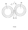
- two sewing needles 91 and 92 are arranged in a conveyance direction T of a material to be sewn 30 at a predetermined interval for the purpose of acquiring robust sewing, and a stitch 95A formed by a sewing needle 91 and a stitch 96A formed by a sewing needle 92 are brought into close contact to each other (for example, Patent document 1 and 2).
- the aforesaid two-needle sewing machine intermittently conveys a material to be sewn 30 to a front side by a conveyor member, but sewing is performed while pressing the material to be sewn 30 with both hands.
- the two-needle sewing machine when the material to be sewn 30 is linearly sewn in the conveyance direction T, the two stitches 95A and 96A are formed to be close to each other as illustrated in FIG. 26 , but when the material to be sewn 30 is sewn rotated from the conveyance direction T of the conveyor member according to a shape thereof, two stitches 95B and 96B are formed to be separated from each other as illustrated in FIG. 27 .
- linear portions 41 and 45 form a pair of stitches 95A and 96A close to each other, but curved parts 42 and 44 of the convex portions 46 and 48 form a pair of stitches 95B and 96B which are separated each other.
- the material to be sewn 40 generally has a pocket shape and materials are filled therein, but when materials are filled, force applied to the convex portions 46 and 48 is large, and as a result, the curve parts 42 and 44 are required to be sewn more robustly than the linear portions 41 and 45.
- the present invention is contrived to solve the above problems, and an object of the present invention is to provide a two-needle sewing machine and a two-needle sewing machine stitch forming method that can improve strength by placing a pair of stitches close to each other in sewing a convex curve part requiring strength at the time of sewing a pocket-shaped material to be sewn.
- a two-needle sewing machine includes: a bed part on which a material to be sewn is placed; a column part erected upward from one side of the bed part; an arm part provided substantially parallel to the bed part at an upper portion of the column part; a needle shaft provided at a leading part of the arm part to reciprocate vertically by a driving motor; two sewing needles mounted on the needle shaft; two horizontal hooks that are provided in the bed part and catch the respective needle thread loops of the two sewing needles; and a conveyor member that conveys the material to be sewn in a direction approximately orthogonal to the bed part, wherein the sewing needles are arranged at both sides of a direction approximately orthogonal to a conveyance direction of the material to be sewn and a sewing needle arranged at a position distant from the column part is provided at a conveyance side of the material to be sewn rather than a sewing needle arranged at a position closer to the column part.
- a two-needle sewing machine stitch forming method including a bed part on which a material to be sewn is placed; a column part erected upward from one side of the bed part; an arm part provided substantially parallel to the bed part at an upper portion of the column part; a needle shaft provided at a leading part of the arm part to reciprocate vertically by a driving motor; two sewing needles mounted on the needle shaft; two horizontal hooks that are provided in the bed part and catch respective loops of needle threads of two sewing needles; and a conveyor member that conveys the material to be sewn in a direction approximately orthogonal to the bed part, wherein the sewing needles are arranged at both sides of a direction approximately orthogonal to a conveyance direction of the material to be sewn and a sewing needle arranged at a position distant from the column part is provided at a conveyance side of the material to be sewn rather than a sewing needle arranged at a position closer to the column part, includes
- a two-needle sewing machine stitch forming method on the periphery of a material to be sewn which has a convex part by a two-needle sewing machine according to claim 3 of the present application, including a bed part on which a material to be sewn is placed; a column part erected upward from one side of the bed part; an arm part provided substantially in parallel to the bed part at an upper portion of the column part; a needle shaft provided at a leading part of the arm part to reciprocate vertically by a driving motor; two sewing needles mounted on the needle shaft; two horizontal hooks that are provided in the bed part and catch respective loops of needle threads of two sewing needles; and a conveyor member that conveys the material to be sewn in a direction approximately orthogonal to the bed part, wherein the sewing needles are arranged at both sides of a direction approximately orthogonal to a conveyance direction of the material to be sewn and a sewing needle arranged at a position distant from the
- the material to be sewn such as the cloth, the leather, and the like
- sewing can be smoothly performed without the material to be sewn to contact the column part.
- the needle shaft moves vertically, and the needle thread loops formed when a pair of sewing needles return after penetrating the material to be sewn is caught by pointed ends of the horizontal hooks to perform a needlework and the conveyor member intermittently conveys the material to be sewn in the conveyance direction to form a pair of stitches.
- the sewing needle arranged at the position distant from the column part is provided at the conveyance side of the material to be sewn rather than the sewing needle arranged at the position closer to the column part, when the material to be sewn is conveyed substantially parallel to the conveyance direction, a pair of stitches having the common stitch width are formed in the material to be sewn, but when the material to be sewn is rotated in the direction distant from the column part with respect to the conveyance direction, a gap between a pair of sewing needles in a direction approximately orthogonal to a sewing direction is narrowed, and as a result, a pair of stitches closely overlap with each other as the stitch width is unlimitedly close to 0.
- a pair of stitches is close to each other during a curved needlework, thereby improving the strength of the stitch. Accordingly, in the two-needle sewing machine and the two-needle sewing machine stitch forming method according to the present invention, when the pocket-shaped material is sewn, the strength can be improved by placing the stitches close to each other at convex curve parts requiring the strength.
- a two-needle sewing machine 1 includes a bed part 3 on which materials to be sewn are placed, a column part 5 erected upward from one side (right side) of the bed part 3, an arm part 6 provided to be substantially parallel to the bed part 3 at an upper part of the column part 5, a needle shaft 11 provided at a leading part of the arm part 6 and reciprocates vertically by a driving motor, two sewing needles 13 and 14 mounted on the needle shaft 11, two horizontal hooks 15 and 16 provided in the bed part 3, to which loops of needle threads of two sewing needles 13 and 14 are caught, respectively, and a conveyor member 21 conveying the materials to be sewn substantially in an orthogonal direction to the bed part 3, as illustrated in FIG. 1 .
- the sewing needles 13 and 14 are arranged at both sides substantially in an orthogonal direction to a conveyance direction T of the materials to be sewn, and the sewing needle 13 arranged at a position distant from the column part 5 provided at a conveyance side of the material to be sewn rather than the sewing needle 14 arranged at a position closer to the column part 5.
- a material to be sewn 30 is conveyed in the conveyance direction T of the conveyor member 21, and as a result, a pair of stitches 31A and 32A having a common stitch width D1 are formed by the pair of sewing needles 13 and 14, as illustrated in FIG. 3 . Further, as illustrated in FIG. 6 , the material to be sewn 30 is conveyed in a direction distant from the column part 5 with respect to the conveyance direction T of the conveyor member 21, and as a result, a pair of stitches 31D and 32D having a stitch width D4 which is smaller than the common stitch width D1 are formed by the pair of sewing needles 13 and 14.
- the above-mentioned method for forming a stitch of the two-needle sewing machine 1 is the method for forming a stitch on the periphery of a pocket-shaped material to be sewn 40 including convex portions 46 and 48, a material to be sewn 40 is conveyed in the conveyance direction of the conveyor member 21, and as a result, the pair of stitches 31A and 32A having the common stitch width D1 are formed by the pair of sewing needles 13 and 14, as illustrated in FIGS. 7 and 8 .
- the material to be sewn 40 is conveyed in the direction distant from the column part 5 with respect to the conveyance direction T of the conveyor member 21, and as a result, the pair of stitches 31D and 32D having the stitch width D4 which is smaller than the common stitch width D1 are formed on the peripheries of the convex portions 46 and 48 by the pair of sewing needles 13 and 14.
- the material to be sewn 40 is placed on the bed part 3 so that the periphery of the material to be sewn 40 (a right linear portion 41) such as a cloth, leather, and the like to face the column part 5 as illustrated in FIG. 11 , the material to be sewn 40 can be smoothly sewn without contacting the column part 5.
- the needle shaft 11 moves vertically, and the needle thread loops formed when the pair of sewing needles 13 and 14 return after penetrating the material to be sewn 40 is caught by pointed ends of the horizontal hooks 15 and 16 to perform a lockstitching and the conveyor member 21 intermittently conveys the material to be sewn 40 in the conveyance direction T to form a pair of stitches 31 and 32.
- the sewing needle 13 arranged at the position distant from the column part 5 is provided at the conveyance side of the material to be sewn 40 rather than the sewing needle 14 arranged at the position close to the column part 5, when the material to be sewn 40 is conveyed substantially parallel to the conveyance direction T, the pair of stitches 31A and 32A having the common stitch width D1 are formed on the material to be sewn 40 as illustrated in FIG. 12 . Further, as illustrated in FIG.
- a sewing machine body 2 of the two-needle sewing machine 1 is constituted by the bed part 3 on which the materials to be sewn such as the cloth, the leather, and the like are placed, the column part 5 erected upward from one side (right side) of the bed part 3, and the arm part 6 provided substantially in parallel to the bed part 3 from the upper side of the column part 5.
- the needle shaft 11 that reciprocates vertically by a driving motor (not illustrated) is provided at the leading part (left portion) of the arm part 6.
- a needle supporting member 12 mounted with the two sewing needles 13 and 14 is fixed to a lower end of the needle shaft 11.
- two horizontal hooks 15 and 16 that are rotated in synchronization with reciprocation of the needle shaft 11 are provided in the bed part 3.
- the horizontal hook 16 positioned at one side (right side) is configured to catch up the loop of the needle thread of the sewing needle 14 and the horizontal hook 15 positioned at the other side (the other surface) (left direction) is configured to hook up the loop of the needle thread of the sewing needle 13.
- the downward conveyor member 21 positioned between the horizontal hooks 15 and 16 is provided in the bed part 3.
- the downward conveyor member 21 is synchronized with the reciprocation of the needle shaft 11 and configured to intermittently convey the materials to be sewn such as the cloth, the leather, and the like in the direction (front side, the T direction illustrated in FIG. 1 ) approximately orthogonal to the bed part 3.
- two stitches are formed substantially parallel to each other by the sewing needles 13 and 14.
- the sewing needles 13 and 14 are separated from each other by approximately 3 mm or more based on the relationship of an outer diameter of the sewing needle itself and the arrangement of the horizontal hook, and the position of one sewing needle 13 and the position of the other sewing needle 14 deviate from each other in order to set the width of the stitch to approximately 0.3 mm.
- the width of the stitch of approximately 0.3 mm is a distance for preventing the stitch formed by the sewing needle 13 and the stitch formed by the sewing needle 14 from overlapping with each other. As illustrated in FIG.
- the sewing needles 13 and 14 are arranged at both sides substantially in the orthogonal direction to the conveyance direction T of the material to be sewn, the sewing needle 13 arranged at the position (left side) distant from the column part 5 is positioned at the front side (the front side of the conveyance direction T), and the sewing needle 14 arranged at the position (right side) closer to the column part 5 is positioned at a rear side (a rear side of the conveyance direction T), and as a result, the sewing needle 13 is provided at the conveyance side of the material to be sewn rather than the sewing needle 14. Therefore, as illustrated in FIG. 3 , the sewing needles 13 and 14 are separated from each other as described above, but the gap between the sewing needles 13 and 14 substantially in the orthogonal direction to the sewing direction P1 is narrowed to reduce the width of the stitch.
- the horizontal hook 15 that hooks up the loop of the needle thread formed by the sewing needle 13 and the horizontal hook 16 that hooks up the loop of the needle thread formed by the sewing needle 14 are arranged at both left and right sides, with the sewing needles 13 and 14 interposed therebetween.
- the horizontal hooks 15 and 16 are arranged at both sides substantially in the orthogonal direction to the conveyance direction T of the material to be sewn, the horizontal hook 15 arranged at the position (left side) distant from the column part 5 is positioned at the front side (the front of the conveyance direction T), and the horizontal hook 16 arranged at the position (right side) closer to the column part 5 is positioned at the rear side (the rear side of the conveyance direction T), and as a result, the horizontal hook 15 is provided at the conveyance side of the material to be sewn rather than the horizontal hook 16.
- the material to be sewn 30 such as the leather, the cloth, and the like is conveyed in the sewing direction P1 substantially parallel to the conveyance direction T of the downward conveyor member 21, and as a result, the pair of stitches 31A and 32A having the common stitch width D1 are formed by the pair of sewing needles 13 and 14.
- the material to be sewn 30 such as the leather, the cloth, and the like is conveyed in the sewing direction P1 substantially parallel to the conveyance direction T of the downward conveyor member 21, and as a result, the pair of stitches 31A and 32A having the common stitch width D1 are formed by the pair of sewing needles 13 and 14.
- the material to be sewn 30 is conveyed to be turned left in a sewing direction P2 (an inclination angle of approximately 5 degrees) distant from the column part 5 with respect to the conveyance direction T of the downward conveyor member 21, and as a result, the gap between the sewing needles 13 and 14 in the direction approximately orthogonal to the sewing direction P2 is further narrowed to form the pair of stitches 31B and 32B having a stitch width D2 smaller than the common stitch width D1 by the pair of sewing needles 13 and 14.
- the material to be sewn 30 is conveyed to be turned left in a sewing direction P3 (at an inclination angle of approximately 10 degrees) distant from the column part 5 with respect to the conveyance direction T of the downward conveyor member 21, and as a result, the gap between the sewing needles 13 and 14 in the direction approximately orthogonal to the sewing direction P3 is further narrowed to form a pair of stitches 31C and 32C having a stitch width D3 smaller than the common stitch width D2 by the pair of sewing needles 13 and 14.
- a sewing direction P3 at an inclination angle of approximately 10 degrees
- the material to be sewn 30 is conveyed to be turned left in a sewing direction P4 (at an inclination angle of approximately 15 degrees) distant from the column part 5 with respect to the conveyance direction T of the downward conveyor member 21, and as a result, the gap between the sewing needles 13 and 14 in the direction approximately orthogonal to the sewing direction P4 is further narrowed to form a pair of stitches 31D and 32D having a stitch width D4 smaller than the common stitch width D3 by the pair of sewing needles 13 and 14.
- the stitches 31D and 32D are brought into close contact with each other and approximately overlap with each other.
- the stitch width is narrowed.
- the left stitch 31 moves to a right side and the right stitch 32 moves to the left side in some cases, but even in this case, since the pair of stitches 31 and 32 are close to each other, robust sewing may be acquired.
- the pocket-shaped material to be sewn 40 is sewn by the two-needle sewing machine 1 as illustrated in FIGS. 7 and 8 .
- the material to be sewn 40 is constituted by a pair of sheet members 40A and 40B such as the cloth, the leather, and the like.
- the sheet members 40A and 40B include a right convex portion 46 and a left convex portion 48 which are curved, and a central concave part 47 which is curved.
- the sheet members 40A and 40B include a right linear portion 41 and a left linear portion 45 which are substantially parallel to each other, a right curve part 42 continues from the right linear portion 41, which is substantially semicircle convex, a left curve part 44 continues from the left linear portion 45, which is substantially semicircle convex, and a central curve part 43 continues to the right curve part 42 and the left curve part 44, which is substantially semicircle concave.
- the right convex portion 46 is formed by the right curve part 42
- the left convex portion 48 is formed by the left curve part 44
- the central convex portion 47 is formed by the central curve part 43.
- sewing is performed by the two-needle sewing machine 1 substantially in parallel along the right linear portion 41 of the material to be sewn 40 comprising a pair of sheets 40A and 40B overlapped each other.
- FIG. 12 in the two-needle sewing machine 1, since the material to be sewn 40 is conveyed in the sewing direction P1 substantially parallel to the conveyance direction T of the downward conveyor member 21, the pair of stitches 31A and 32A having the common stitch width D1 are formed by the pair of sewing needles 13 and 14. As illustrated in FIG.
- the stitches 31D and 32D that sew the peripheries of the right convex portion 46 and the left convex portion 48 closely overlap with each other, and as a result, the gap between the stitches 31E and 32E that sew the periphery of the central concave part 47 becomes larger.
- force applied to the convex portions 46 and 48 is large, but since the stitches 31D and 32D closely overlap with each other, the strength is improved, and as a result, the stitches 31D and 32D are not broadened and the stitches 31D and 32D are not broken easily. Therefore, the material to be sewn 40 is robust and durable. Meanwhile, in the material to be sewn 40, since force applied to the concave part 47 is small, even though the widths of the stitches 31E and 32E are larger, a problem does not particularly occur.
- the material to be sewn 40 is overturned in use as illustrated in FIGS. 9 and 10 , and the stitches 31A to 31E are positioned on the outer periphery of the material to be sewn 40, the stitches 32A to 32E are positioned inside the material to be sewn 40, and the right linear portion 41, the right curve part 42, the central curve part 43, the left curve part 44, and the left linear portion 45 are folded inside. Since the stitches 31D and 32D of the right convex portion 46 and the left convex portion 48 are closely overlap, these portions are reinforced and difficult to broaden and are not easily broken even if materials are filled in the right convex portion 46 and the left convex portion 48 and can be used for a long time.
- the central concave part 47 is slightly weak in strength than the right convex portion 46 and the left convex portion 47 because the stitches 31E and 32E are separated each other, but since the load applied to the central concave part 47 is not so large as applied to the right convex portion 46 and the left convex portion 48, the central concave part 47 may be used for a long time.
- the right convex portion 46 and the left convex portion 48, the right curve part 42 and the left curve part 44 are overturn inside, but since the stitches 31D and 32D overlap with each other, an overturn amount of the right curve part 42 and the left curve part 44 is small, and as a result, the right curve part 42 and the left curve part 44 rarely become an obstacle at the time of filling the material therein, and as a result, the filled material may be closely received up to the vicinity of the stitches 31D and 32D.
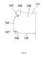
- a sheet back 100 is constituted by a front sheet 101, side sheets 102 and 102, and a back sheet 103, and is filled with an interlining 105 and a pad 106 such as urethane foam, and the like therein. Since the front sheet 101 and the side sheet 102 are sewn in a curved pattern, the sewing is performed by the curved needlework, and since stitches 107 and 108 closely overlap with each other, the sewing is robust. Since the back sheet 103 and the side sheet 102 are sewn straightly, the sewing is performed by a straight needlework and the stitches 107 and 108 are separated each other.
- a two-needle sewing machine 61 illustrated in FIG. 19 will be described.
- sewing needles 71 and 72 are arranged at both sides substantially in the direction orthogonal to the conveyance direction T of the material to be sewn, the sewing needle 72 arranged at a position (left side) distant from a column part 65 is positioned at the back side (the back side of the conveyance direction T), and the sewing needle 71 arranged at the position (right side) closer to the column part 65 is positioned at the front side (the front side of the conveyance direction T), and as a result, the sewing needle 71 is provided at the conveyance side (front side) of the material to be sewn rather than the sewing needle 72.
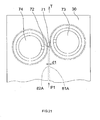
- FIG. 20 in the two-needle sewing machine 61, two stitches are formed substantially in parallel to each other by the sewing needles 71 and 72.
- the two-needle sewing machine 61 is constituted by a bed part 63 on which the materials to be sewn such as the cloth, the leather, and the like are placed, a column part 65 erected upward from one side (right side) of the bed part 63 to the upper side of the bed part 63, and an arm part 66 provided substantially in parallel to the bed part 63 from the upper side of the column part 65.
- a needle shaft 67 that reciprocates orthogonally by a driving motor (not illustrated) is provided at a leading part (left portion) of the arm part 66.
- Two sewing needles 71 and 72 are mounted on the needle shaft 67.
- the bed part 63 includes two horizontal hooks 73 and 74 that catch respective loops of needle threads of the two sewing needles 71 and 72 and a conveyor member 75 that conveys the material to be sewn in a direction approximately orthogonal to the bed part 63.
- the sewing needles 71 and 72 are separated each other by approximately 3 mm or more based on the relationship of an outer diameter of the sewing needle itself and the arrangement of the horizontal hook, and the position of one sewing needle 71 and the position of the other sewing needle 72 deviate from each other in order to set the width of the stitch to approximately 0.3 mm. Therefore, a gap between the sewing needles 71 and 72 is separated each other as described above, but the gap between the sewing needles 71 and 72 in a direction approximately orthogonal to the sewing direction P1 (see FIG. 21 ) is narrowed, and as a result, the width of the stitch is narrowed.
- the material to be sewn is intermittently conveyed to the front side by the conveyor member 75, but sewing is performed with the material to be sewn being pressed with both hands while visually verifying needlework positions of the sewing needles 71 and 72 so as to prevent a sewing failure due to deviation of the needlework positions of the material to be sewn.
- the sewing is performed while verifying a sewing position from the left side because the arm part 66 exists at the right side around the sewing needles 71 and 72.
- the material to be sewn is not sewn linearly at all times and the sewing may be performed in the curved pattern according to a shape thereof.
- the material to be sewn 30 is conveyed to be turned left in a sewing direction P2 (an inclination angle of approximately 5 degrees) distant from the column part 65 with respect to the conveyance direction T of the conveyor member 75, and as a result, the gap between the sewing needles 71 and 72 in the direction approximately orthogonal to the sewing direction P2 is further broadened to form a pair of stitches 81B and 82B having a stitch width d2 larger than the common stitch width d1 by the pair of sewing needles 71 and 72.
- a sewing direction P2 an inclination angle of approximately 5 degrees
- the material to be sewn 30 is conveyed to be turned left in a P3 direction (at an inclination angle of approximately 10 degrees) distant from the column part 5 with respect to the conveyance direction T of the conveyor member 75, and as a result, the gap between the sewing needles 71 and 72 in the direction approximately orthogonal to the sewing direction P3 is further broadened to form a pair of stitches 81C and 82C having a stitch width d3 larger than the common stitch width d2 by the pair of sewing needles 71 and 72.
- a P3 direction at an inclination angle of approximately 10 degrees
- the material to be sewn 30 is conveyed to be turned left in a P4 direction (at an inclination angle of approximately 15 degrees) distant from the column part 5 with respect to the conveyance direction T of the conveyor member 75, and as a result, the gap between the sewing needles 71 and 72 in the direction approximately orthogonal to the sewing direction P4 is further broadened to form a pair of stitches 81D and 82D having a stitch width d4 larger than the stitch width d3 by the pair of sewing needles 71 and 72.
- the stitch width is broadened.
- the aforementioned pocket-shaped material to be sewn 40 is sewn by the two-needle sewing machine 61. Sewing is performed substantially in parallel along the right linear portion 41 of the material to be sewn 40 in which the pair of sheet members 40A and 40A overlap with each other by the two-needle sewing machine 61.
- the pair of stitches 81A and 82A having the common stitch width d1 are formed by the pair of sewing needles 71 and 72.
- the stitches 81D and 82D in which the stitch width d4 formed by the pair of sewing needles 71 and 72 is larger than the common stitch width d1 are formed.
- the pair of stitches 81A and 82A having the common stitch width d1 are formed by the pair of sewing needles 71 and 72.
- the stitch widths d4 of the stitches 81D and 82D that sew the peripheries of the convex portions 46 and 48 are broadened the stitch widths d5 of the stitches 81E and 82E that sew the periphery of the concave part 47 overlap with each other.
- the material to be sewn 40 is filled with material, in general, since force applied to the convex portions 46 and 48 is large, the gap between the stitches 81D and 82D is broadened and strength is short, and as a result, the stitches 81D and 82D are easily broken.
- the two-needle sewing machine 61 when the material to be sewn 40 having the convex portions 46 and 48 is sewn, the widths d4 of the stitches 81D and 82D that sew the peripheries of the convex portions 46 and 48 are broadened, and thus strength is short and when the filled materials are received in the convex portions 46 and 48, the stitches 81D and 82D are easily broadened and easily broken, and thus durability is short.
- the width of the stitch is broadened in the curved needlework, and as a result, strength is short, unlike the two-needle sewing machine 1. Therefore, it can be understood that the two-needle sewing machine 61 is not preferably configured. Accordingly, it is preferable that in the two-needle sewing machine, the sewing needle arranged at the position distant from the column part is provided at the conveyance side of the material to be sewn rather than the sewing needle arranged at the position closer to the column part.
- the present invention can be used in the two-needle sewing machine that forms two stitches in the material to be sewn.
Landscapes
- Engineering & Computer Science (AREA)
- Textile Engineering (AREA)
- Aviation & Aerospace Engineering (AREA)
- Transportation (AREA)
- Mechanical Engineering (AREA)
- Sewing Machines And Sewing (AREA)
Abstract
Description
- The present invention relates to a two-needle sewing machine in which two stitches are formed in materials to be sewn such as a cloth, leather, and the like by reciprocating two sewing needles, and a method for forming a stitch by the two-needle sewing machine.
- In the conventional art, a two-needle sewing machine includes a bed part on which materials to be sewn such as a cloth, leather, and the like are placed, a column part erected upward from one side (right side) of the bed part, and an arm part provided to be substantially parallel to the bed part from an upper part of the column part. A needle shaft that reciprocates vertically by a driving motor (not illustrated) provided at a leading part (left part) of the arm part. Two sewing needles are mounted on the needle shaft. The bed part includes two horizontal hooks by which loops of needle threads of two sewing needles are caught, and a conveyor member conveying the materials to be sewn such as the cloth, the leather, and the like substantially in a direction orthogonal to the bed part.
- The conventional two-needle sewing machine closely forms two stitches by two sewing needles. As illustrated in
FIG. 26 , twosewing needles sewn 30 at a predetermined interval for the purpose of acquiring robust sewing, and astitch 95A formed by asewing needle 91 and astitch 96A formed by asewing needle 92 are brought into close contact to each other (for example,Patent document 1 and 2). -
- Patent document 1: Utility Model Publication No.
52-10527 - Patent document 2: Patent No.
4456846 - The aforesaid two-needle sewing machine intermittently conveys a material to be
sewn 30 to a front side by a conveyor member, but sewing is performed while pressing the material to besewn 30 with both hands. In the two-needle sewing machine, when the material to besewn 30 is linearly sewn in the conveyance direction T, the twostitches FIG. 26 , but when the material to besewn 30 is sewn rotated from the conveyance direction T of the conveyor member according to a shape thereof, twostitches FIG. 27 . That is, when the two-needle sewing machine sews the material to be sewn 30 round by rotating the material to besewn 30 from the conveyance direction T of the conveyor member, a pair ofsewing needles stitches - As illustrated in
FIG. 28 , when a material to besewn 40 havingconvex portions linear portions stitches curved parts convex portions stitches sewn 40 generally has a pocket shape and materials are filled therein, but when materials are filled, force applied to theconvex portions curve parts linear portions curve parts stitches stitches convex portions stitches convex portions - The present invention is contrived to solve the above problems, and an object of the present invention is to provide a two-needle sewing machine and a two-needle sewing machine stitch forming method that can improve strength by placing a pair of stitches close to each other in sewing a convex curve part requiring strength at the time of sewing a pocket-shaped material to be sewn.
- In order to achieve the above object, a two-needle sewing machine according to
claim 1 of the present application includes: a bed part on which a material to be sewn is placed; a column part erected upward from one side of the bed part; an arm part provided substantially parallel to the bed part at an upper portion of the column part; a needle shaft provided at a leading part of the arm part to reciprocate vertically by a driving motor; two sewing needles mounted on the needle shaft; two horizontal hooks that are provided in the bed part and catch the respective needle thread loops of the two sewing needles; and a conveyor member that conveys the material to be sewn in a direction approximately orthogonal to the bed part, wherein the sewing needles are arranged at both sides of a direction approximately orthogonal to a conveyance direction of the material to be sewn and a sewing needle arranged at a position distant from the column part is provided at a conveyance side of the material to be sewn rather than a sewing needle arranged at a position closer to the column part. - In order to achieve the object, a two-needle sewing machine stitch forming method according to
claim 2 of the present application including a bed part on which a material to be sewn is placed; a column part erected upward from one side of the bed part; an arm part provided substantially parallel to the bed part at an upper portion of the column part; a needle shaft provided at a leading part of the arm part to reciprocate vertically by a driving motor; two sewing needles mounted on the needle shaft; two horizontal hooks that are provided in the bed part and catch respective loops of needle threads of two sewing needles; and a conveyor member that conveys the material to be sewn in a direction approximately orthogonal to the bed part, wherein the sewing needles are arranged at both sides of a direction approximately orthogonal to a conveyance direction of the material to be sewn and a sewing needle arranged at a position distant from the column part is provided at a conveyance side of the material to be sewn rather than a sewing needle arranged at a position closer to the column part, includes: forming a pair of stitches having a common stitch width by a pair of sewing needles by conveying the material to be sewn in a conveyance direction of the conveyor member; and forming a pair of stitches having a stitch width smaller than the common stitch width by a pair of sewing needles by conveying the material to be sewn in a direction distant from the column part with respect to the conveyance direction of the conveyor member. - In order to achieve the above object, a two-needle sewing machine stitch forming method on the periphery of a material to be sewn, which has a convex part by a two-needle sewing machine according to
claim 3 of the present application, including a bed part on which a material to be sewn is placed; a column part erected upward from one side of the bed part; an arm part provided substantially in parallel to the bed part at an upper portion of the column part; a needle shaft provided at a leading part of the arm part to reciprocate vertically by a driving motor; two sewing needles mounted on the needle shaft; two horizontal hooks that are provided in the bed part and catch respective loops of needle threads of two sewing needles; and a conveyor member that conveys the material to be sewn in a direction approximately orthogonal to the bed part, wherein the sewing needles are arranged at both sides of a direction approximately orthogonal to a conveyance direction of the material to be sewn and a sewing needle arranged at a position distant from the column part is provided at a conveyance side of the material to be sewn rather than a sewing needle arranged at a position closer to the column part, includes: forming a pair of stitches having a common stitch width by a pair of sewing needles by conveying the material to be sewn in a conveyance direction of the conveyor member; and forming a pair of stitches having a stitch width smaller than the common stitch width on the periphery of a convex portion by a pair of sewing needles by conveying the material to be sewn in a direction distant from the column part with respect to the conveyance direction of the conveyor member. - In the two-needle sewing machine and the two-needle sewing machine stitch forming method according to the present invention, since the material to be sewn, such as the cloth, the leather, and the like, is placed on the bed part so that the periphery of the material to be sewn faces column part, sewing can be smoothly performed without the material to be sewn to contact the column part. In the two-needle sewing machine and the two-needle sewing machine stitch forming method according to the present invention, when the two-needle sewing machine is driven, the needle shaft moves vertically, and the needle thread loops formed when a pair of sewing needles return after penetrating the material to be sewn is caught by pointed ends of the horizontal hooks to perform a needlework and the conveyor member intermittently conveys the material to be sewn in the conveyance direction to form a pair of stitches. In the two-needle sewing machine and the two-needle sewing machine stitch forming method according to the present invention, since the sewing needle arranged at the position distant from the column part is provided at the conveyance side of the material to be sewn rather than the sewing needle arranged at the position closer to the column part, when the material to be sewn is conveyed substantially parallel to the conveyance direction, a pair of stitches having the common stitch width are formed in the material to be sewn, but when the material to be sewn is rotated in the direction distant from the column part with respect to the conveyance direction, a gap between a pair of sewing needles in a direction approximately orthogonal to a sewing direction is narrowed, and as a result, a pair of stitches closely overlap with each other as the stitch width is unlimitedly close to 0. As such, in the two-needle sewing machine and the two-needle sewing machine stitch forming method according to the present invention, a pair of stitches is close to each other during a curved needlework, thereby improving the strength of the stitch. Accordingly, in the two-needle sewing machine and the two-needle sewing machine stitch forming method according to the present invention, when the pocket-shaped material is sewn, the strength can be improved by placing the stitches close to each other at convex curve parts requiring the strength.
-
-
FIG. 1 is an overall perspective view illustrating an embodiment of a two-needle sewing machine according to the present invention. -
FIG. 2 is an explanatory diagram of primary components of the two-needle sewing machine ofFIG. 1 . -
FIG. 3 is an explanatory diagram illustrating a common two-needle sewing machine stitch forming method ofFIG. 1 . -
FIG. 4 is an explanatory diagram illustrating a method for forming an inclined stitch of the two-needle sewing machine ofFIG. 1 . -
FIG. 5 is an explanatory diagram illustrating a method for forming an inclined stitch of the two-needle sewing machine ofFIG. 1 . -
FIG. 6 is an explanatory diagram illustrating a method for forming an inclined stitch of the two-needle sewing machine ofFIG. 1 . -
FIG. 7 is an explanatory diagram of a material to be sewn which is sewn by the two-needle sewing machine ofFIG. 1 . -
FIG. 8 is a perspective view of the material to be sewn which is sewn by the two-needle sewing machine ofFIG. 1 . -
FIG. 9 is an explanatory diagram of a state in which the material to be sewn ofFIG. 7 overturns. -
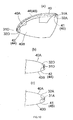
FIG. 10 is an explanatory diagram of primary components of the material to be sewn ofFIG. 9 , in which (a) is a cross-sectional view taken along line a-a, (b) is a cross-sectional view taken along line b-b, and (c) is a cross-sectional view taken along line c-c. -
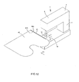
FIG. 11 is a perspective view illustrating a first sewing sequence by the two-needle sewing machine ofFIG. 1 . -
FIG. 12 is a perspective view illustrating a second sewing sequence by the two-needle sewing machine ofFIG. 1 . -
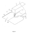
FIG. 13 is a perspective view illustrating a third sewing sequence by the two-needle sewing machine ofFIG. 1 . -
FIG. 14 is a perspective view illustrating a fourth sewing sequence by the two-needle sewing machine ofFIG. 1 . -
FIG. 15 is a perspective view illustrating a fifth sewing sequence by the two-needle sewing machine ofFIG. 1 . -
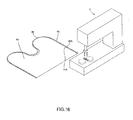
FIG. 16 is a perspective view illustrating a sixth sewing sequence by the two-needle sewing machine ofFIG. 1 . -
FIG. 17 is a perspective view illustrating a detailed example of a material to be sewn. -
FIG. 18 is a cross-sectional view of primary components ofFIG. 17 taken along line d-d. -
FIG. 19 is an overall perspective view illustrating another embodiment of the two-needle sewing machine. -
FIG. 20 is an explanatory diagram of primary components of the two-needle sewing machine ofFIG. 19 . -
FIG. 21 is an explanatory diagram illustrating a common two-needle sewing machine stitch forming method ofFIG. 19 . -
FIG. 22 is an explanatory diagram illustrating a method for forming an inclined stitch of the two-needle sewing machine ofFIG. 19 . -
FIG. 23 is an explanatory diagram illustrating a method for forming an inclined stitch of the two-needle sewing machine ofFIG. 19 . -
FIG. 24 is an explanatory diagram illustrating a method for forming an inclined stitch of the two-needle sewing machine ofFIG. 19 . -
FIG. 25 is an explanatory diagram of a material to be sewn which is sewn by the two-needle sewing machine ofFIG. 19 . -
FIG. 26 is an explanatory diagram illustrating a common two-needle sewing machine stitch forming method in the conventional art. -
FIG. 27 is an explanatory diagram illustrating a method for forming an inclined stitch of the two-needle sewing machine in the conventional art. -
FIG. 28 is an explanatory diagram of a material to be sewn which is sewn by the two-needle sewing machine in the conventional art. - A two-
needle sewing machine 1 includes abed part 3 on which materials to be sewn are placed, acolumn part 5 erected upward from one side (right side) of thebed part 3, anarm part 6 provided to be substantially parallel to thebed part 3 at an upper part of thecolumn part 5, aneedle shaft 11 provided at a leading part of thearm part 6 and reciprocates vertically by a driving motor, twosewing needles needle shaft 11, twohorizontal hooks bed part 3, to which loops of needle threads of twosewing needles conveyor member 21 conveying the materials to be sewn substantially in an orthogonal direction to thebed part 3, as illustrated inFIG. 1 . In the two-needle sewing machine 1, the sewing needles 13 and 14 are arranged at both sides substantially in an orthogonal direction to a conveyance direction T of the materials to be sewn, and thesewing needle 13 arranged at a position distant from thecolumn part 5 provided at a conveyance side of the material to be sewn rather than thesewing needle 14 arranged at a position closer to thecolumn part 5. - In a method for forming a stitch of the two-
needle sewing machine 1, a material to be sewn 30 is conveyed in the conveyance direction T of theconveyor member 21, and as a result, a pair ofstitches sewing needles FIG. 3 . Further, as illustrated inFIG. 6 , the material to be sewn 30 is conveyed in a direction distant from thecolumn part 5 with respect to the conveyance direction T of theconveyor member 21, and as a result, a pair ofstitches sewing needles - The above-mentioned method for forming a stitch of the two-
needle sewing machine 1 is the method for forming a stitch on the periphery of a pocket-shaped material to be sewn 40 includingconvex portions conveyor member 21, and as a result, the pair ofstitches sewing needles FIGS. 7 and8 . Further, the material to be sewn 40 is conveyed in the direction distant from thecolumn part 5 with respect to the conveyance direction T of theconveyor member 21, and as a result, the pair ofstitches convex portions sewing needles - In the two-
needle sewing machine 1, since the material to be sewn 40 is placed on thebed part 3 so that the periphery of the material to be sewn 40 (a right linear portion 41) such as a cloth, leather, and the like to face thecolumn part 5 as illustrated inFIG. 11 , the material to be sewn 40 can be smoothly sewn without contacting thecolumn part 5. When the two-needle sewing machine 1 is driven, theneedle shaft 11 moves vertically, and the needle thread loops formed when the pair ofsewing needles horizontal hooks conveyor member 21 intermittently conveys the material to be sewn 40 in the conveyance direction T to form a pair of stitches 31 and 32. In the two-needle sewing machine 1, since thesewing needle 13 arranged at the position distant from thecolumn part 5 is provided at the conveyance side of the material to be sewn 40 rather than thesewing needle 14 arranged at the position close to thecolumn part 5, when the material to be sewn 40 is conveyed substantially parallel to the conveyance direction T, the pair ofstitches FIG. 12 . Further, as illustrated inFIG. 13 , when the material to be sewn 40 is rotated in the direction (left direction L) distant from thecolumn part 5 with respect to the conveyance direction T, a gap between the pair ofsewing needles stitches needle sewing machine 1, the pair of stitches 31 and 32 is close to each other during a curved needlework, and thus the strength of the stitch may be improved. Accordingly, in the two-needle sewing machine 1, when sewing the pocket-shaped material to be sewn 40 having theconvex portions convex curve parts - Further, the two-needle sewing machine will be described in detail. As illustrated in
FIG. 1 , asewing machine body 2 of the two-needle sewing machine 1 is constituted by thebed part 3 on which the materials to be sewn such as the cloth, the leather, and the like are placed, thecolumn part 5 erected upward from one side (right side) of thebed part 3, and thearm part 6 provided substantially in parallel to thebed part 3 from the upper side of thecolumn part 5. - The
needle shaft 11 that reciprocates vertically by a driving motor (not illustrated) is provided at the leading part (left portion) of thearm part 6. Aneedle supporting member 12 mounted with the twosewing needles needle shaft 11. Further, twohorizontal hooks needle shaft 11 are provided in thebed part 3. Thehorizontal hook 16 positioned at one side (right side) is configured to catch up the loop of the needle thread of thesewing needle 14 and thehorizontal hook 15 positioned at the other side (the other surface) (left direction) is configured to hook up the loop of the needle thread of thesewing needle 13. - Further, the
downward conveyor member 21 positioned between thehorizontal hooks bed part 3. Thedownward conveyor member 21 is synchronized with the reciprocation of theneedle shaft 11 and configured to intermittently convey the materials to be sewn such as the cloth, the leather, and the like in the direction (front side, the T direction illustrated inFIG. 1 ) approximately orthogonal to thebed part 3. - In the two-
needle sewing machine 1, two stitches are formed substantially parallel to each other by the sewing needles 13 and 14. The sewing needles 13 and 14 are separated from each other by approximately 3 mm or more based on the relationship of an outer diameter of the sewing needle itself and the arrangement of the horizontal hook, and the position of onesewing needle 13 and the position of theother sewing needle 14 deviate from each other in order to set the width of the stitch to approximately 0.3 mm. The width of the stitch of approximately 0.3 mm is a distance for preventing the stitch formed by thesewing needle 13 and the stitch formed by thesewing needle 14 from overlapping with each other. As illustrated inFIG. 2 , in the two-needle sewing machine 1, the sewing needles 13 and 14 are arranged at both sides substantially in the orthogonal direction to the conveyance direction T of the material to be sewn, thesewing needle 13 arranged at the position (left side) distant from thecolumn part 5 is positioned at the front side (the front side of the conveyance direction T), and thesewing needle 14 arranged at the position (right side) closer to thecolumn part 5 is positioned at a rear side (a rear side of the conveyance direction T), and as a result, thesewing needle 13 is provided at the conveyance side of the material to be sewn rather than thesewing needle 14. Therefore, as illustrated inFIG. 3 , the sewing needles 13 and 14 are separated from each other as described above, but the gap between the sewing needles 13 and 14 substantially in the orthogonal direction to the sewing direction P1 is narrowed to reduce the width of the stitch. - The
horizontal hook 15 that hooks up the loop of the needle thread formed by thesewing needle 13 and thehorizontal hook 16 that hooks up the loop of the needle thread formed by thesewing needle 14 are arranged at both left and right sides, with the sewing needles 13 and 14 interposed therebetween. That is, thehorizontal hooks horizontal hook 15 arranged at the position (left side) distant from thecolumn part 5 is positioned at the front side (the front of the conveyance direction T), and thehorizontal hook 16 arranged at the position (right side) closer to thecolumn part 5 is positioned at the rear side (the rear side of the conveyance direction T), and as a result, thehorizontal hook 15 is provided at the conveyance side of the material to be sewn rather than thehorizontal hook 16. - As illustrated in
FIG. 3 , in the two-needle sewing machine 1, the material to be sewn 30 such as the leather, the cloth, and the like is conveyed in the sewing direction P1 substantially parallel to the conveyance direction T of thedownward conveyor member 21, and as a result, the pair ofstitches sewing needles FIG. 4 , in the two-needle sewing machine 1, the material to be sewn 30 is conveyed to be turned left in a sewing direction P2 (an inclination angle of approximately 5 degrees) distant from thecolumn part 5 with respect to the conveyance direction T of thedownward conveyor member 21, and as a result, the gap between the sewing needles 13 and 14 in the direction approximately orthogonal to the sewing direction P2 is further narrowed to form the pair ofstitches sewing needles - As illustrated in
FIG. 5 , in the two-needle sewing machine 1, the material to be sewn 30 is conveyed to be turned left in a sewing direction P3 (at an inclination angle of approximately 10 degrees) distant from thecolumn part 5 with respect to the conveyance direction T of thedownward conveyor member 21, and as a result, the gap between the sewing needles 13 and 14 in the direction approximately orthogonal to the sewing direction P3 is further narrowed to form a pair ofstitches sewing needles FIG. 6 , in the two-needle sewing machine 1, the material to be sewn 30 is conveyed to be turned left in a sewing direction P4 (at an inclination angle of approximately 15 degrees) distant from thecolumn part 5 with respect to the conveyance direction T of thedownward conveyor member 21, and as a result, the gap between the sewing needles 13 and 14 in the direction approximately orthogonal to the sewing direction P4 is further narrowed to form a pair ofstitches sewing needles stitches needle sewing machine 1, as a left-turn angle of the material to be sewn 30 is larger, the stitch width is narrowed. Meanwhile, in the two-needle sewing machine 1, when the left-turn angle of the material to be sewn 30 is made larger, the left stitch 31 moves to a right side and the right stitch 32 moves to the left side in some cases, but even in this case, since the pair of stitches 31 and 32 are close to each other, robust sewing may be acquired. - The pocket-shaped material to be sewn 40 is sewn by the two-
needle sewing machine 1 as illustrated inFIGS. 7 and8 . The material to be sewn 40 is constituted by a pair ofsheet members sheet members convex portion 46 and a leftconvex portion 48 which are curved, and a centralconcave part 47 which is curved. Thesheet members linear portion 41 and a leftlinear portion 45 which are substantially parallel to each other, aright curve part 42 continues from the rightlinear portion 41, which is substantially semicircle convex, aleft curve part 44 continues from the leftlinear portion 45, which is substantially semicircle convex, and acentral curve part 43 continues to theright curve part 42 and theleft curve part 44, which is substantially semicircle concave. And the rightconvex portion 46 is formed by theright curve part 42, the leftconvex portion 48 is formed by theleft curve part 44, and the centralconvex portion 47 is formed by thecentral curve part 43. - As illustrated in
FIG. 11 , sewing is performed by the two-needle sewing machine 1 substantially in parallel along the rightlinear portion 41 of the material to be sewn 40 comprising a pair ofsheets FIG. 12 , in the two-needle sewing machine 1, since the material to be sewn 40 is conveyed in the sewing direction P1 substantially parallel to the conveyance direction T of thedownward conveyor member 21, the pair ofstitches sewing needles FIG. 13 , in the two-needle sewing machine 1, when sewing is performed along theright curve part 42, since the material to be sewn 40 is inclined and conveyed in the direction (left direction L) distant from thecolumn part 5 with respect to the conveyance direction T of thedownward conveyor member 21, the width of the stitch formed by the pair ofsewing needles stitches - As illustrated in
FIG. 14 , in the two-needle sewing machine 1, when sewing is performed on theright curve part 42 along thecentral curve part 43, since the material to be sewn 40 is inclined and conveyed in a direction (right direction R) close to thecolumn part 5 with respect to the conveyance direction T of thedownward conveyor member 21, a gap between a pair ofstitches sewing needles FIG. 15 , in the two-needle sewing machine 1, when sewing is performed along theleft curve part 44 on thecentral curve part 43, since the material to be sewn 40 is inclined and conveyed in the direction (left direction L) distant from thecolumn part 5 with respect to the conveyance direction T of thedownward conveyor member 21, the pair ofstitches sewing needles FIG. 16 , in the two-needle sewing machine 1, when sewing is performed along the leftlinear portion 45 on theleft curve part 44, since the material to be sewn 40 is inclined and conveyed in the direction (right direction R) close to thecolumn part 5 with respect to the conveyance direction T of thedownward conveyor member 21, a gap between the pair ofstitches sewing needles FIG. 7 ). - As illustrated in
FIGS. 7 and8 , in the material to be sewn 40, thestitches convex portion 46 and the leftconvex portion 48 closely overlap with each other, and as a result, the gap between thestitches concave part 47 becomes larger. In the material to be sewn 40, force applied to theconvex portions stitches stitches stitches concave part 47 is small, even though the widths of thestitches - The material to be sewn 40 is overturned in use as illustrated in
FIGS. 9 and10 , and thestitches 31A to 31E are positioned on the outer periphery of the material to be sewn 40, thestitches 32A to 32E are positioned inside the material to be sewn 40, and the rightlinear portion 41, theright curve part 42, thecentral curve part 43, theleft curve part 44, and the leftlinear portion 45 are folded inside. Since thestitches convex portion 46 and the leftconvex portion 48 are closely overlap, these portions are reinforced and difficult to broaden and are not easily broken even if materials are filled in the rightconvex portion 46 and the leftconvex portion 48 and can be used for a long time. The centralconcave part 47 is slightly weak in strength than the rightconvex portion 46 and the leftconvex portion 47 because thestitches concave part 47 is not so large as applied to the rightconvex portion 46 and the leftconvex portion 48, the centralconcave part 47 may be used for a long time. Further, the rightconvex portion 46 and the leftconvex portion 48, theright curve part 42 and theleft curve part 44 are overturn inside, but since thestitches right curve part 42 and theleft curve part 44 is small, and as a result, theright curve part 42 and theleft curve part 44 rarely become an obstacle at the time of filling the material therein, and as a result, the filled material may be closely received up to the vicinity of thestitches - A case in which the material to be sewn is the leather sheet of the vehicle seat will be described based on
FIGS. 17 and18 . A sheet back 100 is constituted by afront sheet 101,side sheets back sheet 103, and is filled with aninterlining 105 and apad 106 such as urethane foam, and the like therein. Since thefront sheet 101 and theside sheet 102 are sewn in a curved pattern, the sewing is performed by the curved needlework, and sincestitches back sheet 103 and theside sheet 102 are sewn straightly, the sewing is performed by a straight needlework and thestitches front sheet 101 in order to support movement of a driver, but since the periphery of thefront sheet 101 is reinforced by a lined needlework of the stitch, it is unlikely that the stitch will stretch or be broken, and as a result, the safety is secured and furthermore, it is unlikely that a part of thepad 106 is exposed, thereby damaging an appearance. So many pocket-shaped materials to be sewn, in general, are formed only by convex curve portions, and if the curved needlework is performed along the convex curve portions by thesewing machine 1, a pair of stitches which are close to each other always can be made, and thus robust sewing can be performed. - A two-
needle sewing machine 61 illustrated inFIG. 19 will be described. In the two-needle sewing machine 61, sewing needles 71 and 72 are arranged at both sides substantially in the direction orthogonal to the conveyance direction T of the material to be sewn, thesewing needle 72 arranged at a position (left side) distant from acolumn part 65 is positioned at the back side (the back side of the conveyance direction T), and thesewing needle 71 arranged at the position (right side) closer to thecolumn part 65 is positioned at the front side (the front side of the conveyance direction T), and as a result, thesewing needle 71 is provided at the conveyance side (front side) of the material to be sewn rather than thesewing needle 72. Meanwhile, as illustrated inFIG. 20 , in the two-needle sewing machine 61, two stitches are formed substantially in parallel to each other by the sewing needles 71 and 72. - As illustrated in
FIG. 19 , the two-needle sewing machine 61 is constituted by abed part 63 on which the materials to be sewn such as the cloth, the leather, and the like are placed, acolumn part 65 erected upward from one side (right side) of thebed part 63 to the upper side of thebed part 63, and anarm part 66 provided substantially in parallel to thebed part 63 from the upper side of thecolumn part 65. Aneedle shaft 67 that reciprocates orthogonally by a driving motor (not illustrated) is provided at a leading part (left portion) of thearm part 66. Twosewing needles needle shaft 67. Thebed part 63 includes twohorizontal hooks sewing needles conveyor member 75 that conveys the material to be sewn in a direction approximately orthogonal to thebed part 63. - The sewing needles 71 and 72 are separated each other by approximately 3 mm or more based on the relationship of an outer diameter of the sewing needle itself and the arrangement of the horizontal hook, and the position of one
sewing needle 71 and the position of theother sewing needle 72 deviate from each other in order to set the width of the stitch to approximately 0.3 mm. Therefore, a gap between the sewing needles 71 and 72 is separated each other as described above, but the gap between the sewing needles 71 and 72 in a direction approximately orthogonal to the sewing direction P1 (seeFIG. 21 ) is narrowed, and as a result, the width of the stitch is narrowed. - In the two-
needle sewing machine 61, the material to be sewn is intermittently conveyed to the front side by theconveyor member 75, but sewing is performed with the material to be sewn being pressed with both hands while visually verifying needlework positions of the sewing needles 71 and 72 so as to prevent a sewing failure due to deviation of the needlework positions of the material to be sewn. The sewing is performed while verifying a sewing position from the left side because thearm part 66 exists at the right side around the sewing needles 71 and 72. The material to be sewn is not sewn linearly at all times and the sewing may be performed in the curved pattern according to a shape thereof. In the case where the sewing is performed in the curved pattern, when sewing is performed by rotating the material to be sewn in the right direction (R direction) so that the material to be sewn is close to thecolumn part 65 with respect to the conveyance direction T of theconveyor member 75, the stitch is not shown well by existence of thearm part 66, and as a result, the sewing failure, and the like may occur. Further, when the material to be sewn is rotated in the right direction (R direction), since the material to be sewn contacts thecolumn part 65, it is difficult for an operator to perform sewing as intended. Therefore, in the two-needle sewing machine 61, when sewing is performed in a curved pattern, sewing is performed by rotating the material to be sewn in the left direction (L direction) so that the material to be sewn is distant from thecolumn part 65 with respect to the conveyance direction T of theconveyor member 75. - As illustrated in
FIG. 21 , in the two-needle sewing machine 61, since the material to be sewn 30 is conveyed in the sewing direction P1 substantially parallel to the conveyance direction T of theconveyor member 75, a pair ofstitches sewing needles FIG. 22 , in the two-needle sewing machine 61, the material to be sewn 30 is conveyed to be turned left in a sewing direction P2 (an inclination angle of approximately 5 degrees) distant from thecolumn part 65 with respect to the conveyance direction T of theconveyor member 75, and as a result, the gap between the sewing needles 71 and 72 in the direction approximately orthogonal to the sewing direction P2 is further broadened to form a pair ofstitches sewing needles - As illustrated in
FIG. 23 , in the two-needle sewing machine 61, the material to be sewn 30 is conveyed to be turned left in a P3 direction (at an inclination angle of approximately 10 degrees) distant from thecolumn part 5 with respect to the conveyance direction T of theconveyor member 75, and as a result, the gap between the sewing needles 71 and 72 in the direction approximately orthogonal to the sewing direction P3 is further broadened to form a pair ofstitches sewing needles FIG. 24 , in the two-needle sewing machine 61, the material to be sewn 30 is conveyed to be turned left in a P4 direction (at an inclination angle of approximately 15 degrees) distant from thecolumn part 5 with respect to the conveyance direction T of theconveyor member 75, and as a result, the gap between the sewing needles 71 and 72 in the direction approximately orthogonal to the sewing direction P4 is further broadened to form a pair ofstitches sewing needles needle sewing machine 61, as a left-turn angle of the material to be sewn 30 is larger, the stitch width is broadened. - As illustrated in
FIG. 25 , the aforementioned pocket-shaped material to be sewn 40 is sewn by the two-needle sewing machine 61. Sewing is performed substantially in parallel along the rightlinear portion 41 of the material to be sewn 40 in which the pair ofsheet members needle sewing machine 61. In the two-needle sewing machine 61, since the material to be sewn 40 is conveyed in the P1 direction substantially parallel to the conveyance direction T of theconveyor member 75, the pair ofstitches sewing needles needle sewing machine 61, when sewing is performed along theright curve part 42, since the material to be sewn 40 is inclined and conveyed in a direction (left direction L) distant from thecolumn part 65 with respect to the conveyance direction T of theconveyor member 75, thestitches sewing needles - In the two-
needle sewing machine 61, when sewing is performed along thecentral curve part 43 from theright curve part 42, since the material to be sewn 40 is inclined and conveyed in a direction (right direction R) close to thecolumn part 65 with respect to the conveyance direction T of theconveyor member 75, a stitch width d5 formed by the pair ofsewing needles needle sewing machine 61, when sewing is performed along theleft curve part 44 from thecentral curve part 43, since the material to be sewn 40 is inclined and conveyed in the direction (left direction L) distant from thecolumn part 65 with respect to the conveyance direction T of theconveyor member 75, thestitches sewing needles needle sewing machine 61, when sewing is performed along the leftlinear portion 45 from theleft curve part 44, since the material to be sewn 40 is inclined and conveyed in a direction close to thecolumn part 65 with respect to the conveyance direction T of theconveyor member 75, the pair ofstitches sewing needles - In the material to be sewn 40, the stitch widths d4 of the
stitches convex portions stitches concave part 47 overlap with each other. When the material to be sewn 40 is filled with material, in general, since force applied to theconvex portions stitches stitches needle sewing machine 61, when the material to be sewn 40 having theconvex portions stitches convex portions convex portions stitches needle sewing machine 61, the width of the stitch is broadened in the curved needlework, and as a result, strength is short, unlike the two-needle sewing machine 1. Therefore, it can be understood that the two-needle sewing machine 61 is not preferably configured. Accordingly, it is preferable that in the two-needle sewing machine, the sewing needle arranged at the position distant from the column part is provided at the conveyance side of the material to be sewn rather than the sewing needle arranged at the position closer to the column part. - The present invention can be used in the two-needle sewing machine that forms two stitches in the material to be sewn.
-
- D1 Stitch width
- D2 Stitch width
- D3 Stitch width
- D4 Stitch width
- D5 Stitch width
- L Left direction
- P Sewing direction (sewing direction)
- P1 Stitch direction
- P2 Stitch direction
- P3 Stitch direction
- P4 Stitch direction
- P5 Stitch direction
- R Right direction
- T Conveyance direction
- 1 Two-needle sewing machine
- 2 Sewing machine body
- 3 Bed part
- 5 Column part
- 6 Arm part
- 11 Needle shaft
- 12 Needle supporting member
- 13 Sewing needle
- 14 Sewing needle
- 15 Horizontal hook
- 16 Horizontal hook
- 21 Downward conveyor member
- 30 Material to be sewn
- 31 Stitch
- 31A-31E Stitch
- 32 Stitch
- 32A-32E Stitch
- 40 Material to be sewn
- 40A Sheet
- 40B Sheet
- 41 Right linear portion
- 42 Right curve portion
- 43 Central curve portion
- 44 Left curve portion
- 45 Left linear portion
- 46 Right convex portion
- 47 Central concave part
- 48 Left convex portion
- 61 Two-needle sewing machine
- 63 Bed part
- 65 Column part
- 66 Arm part
- 67 Needle shaft
- 71 Sewing needle
- 72 Sewing needle
- 73 Horizontal hook
- 74 Horizontal hook
- 75 Conveyor member
- 81 Stitch
- 81A-81E Stitch
- 82 Stitch
- 82A-82E Stitch
- 91 Sewing needle
- 92 Sewing needle
- 93 Horizontal hook
- 94 Horizontal hook
- 95 Stitch
- 96 Stitch
- 100 Sheet back
- 101 Front sheet
- 102 Side sheet
- 103 Back sheet
- 105 Interlining
- 106 Pad
- 107 Stitch
- 108 Stitch
Claims (3)
- A two-needle sewing machine, comprising:a bed part on which a material to be sewn is placed;a column part erected upward from one side of the bed part;an arm part provided substantially parallel to the bed part at an upper portion of the column part;a needle shaft provided at a leading part of the arm part to reciprocate vertically by a driving motor;two sewing needles mounted on the needle shaft;two horizontal hooks provided in the bed part and catch respective loops of needle threads of two sewing needles; anda conveyor member that conveys the material to be sewn in a direction approximately orthogonal to the bed part,wherein the sewing needles are arranged at both sides of a direction approximately orthogonal to a conveyance direction of the material to be sewn and a sewing needle arranged at a position distant from the column part is provided at a conveyance side of the material to be sewn rather than a sewing needle arranged at a position closer to the column part.
- A method for forming a stitch of a two-needle sewing machine including:a bed part on which a material to be sewn is placed;a column part erected upward from one side of the bed part;an arm part provided substantially parallel to the bed part at an upper portion of the column part;a needle shaft provided at a leading part of the arm part to reciprocate vertically by a driving motor;two sewing needles mounted on the needle shaft;two horizontal hooks provided in the bed part and catch respective loops of needle threads of two sewing needles; anda conveyor member that conveys the material to be sewn in a direction approximately orthogonal to the bed part, the sewing needles are arranged at both sides of a direction approximately orthogonal to a conveyance direction of the material to be sewn and a sewing needle arranged at a position distant from the column part is provided at a conveyance side of the material to be sewn rather than a sewing needle arranged at a position closer to the column part, the method comprising:forming a pair of stitches having a common stitch width by a pair of sewing needles by conveying the material to be sewn in a conveyance direction of the conveyor member; andforming a pair of stitches having a stitch width smaller than the common stitch width by a pair of sewing needles by conveying the material to be sewn in a direction distant from the column part with respect to the conveyance direction of the conveyor member.
- A method for forming a stitch on the periphery of a material to be sewn having a convex part by a two-needle sewing machine including:a bed part on which a material to be sewn is placed;a column part erected upward from one side of the bed part;an arm part provided substantially parallel to the bed part at an upper portion of the column part;a needle shaft provided at a leading part of the arm part to reciprocate vertically by a driving motor;two sewing needles mounted on the needle shaft;two horizontal hooks that are provided in the bed part and catch respective loops of needle threads of two sewing needles; anda conveyor member that conveys the material to be sewn in a direction approximately orthogonal to the bed part,wherein the sewing needles are arranged at both sides of a direction approximately orthogonal to a conveyance direction of the material to be sewn and a sewing needle arranged at a position distant from the column part is provided at a conveyance side of the material to be sewn rather than a sewing needle arranged at a position closer to the column part, the method comprising:forming a pair of stitches having a common stitch width by a pair of sewing needles by conveying the material to be sewn in a conveyance direction of the conveyor member; andforming a pair of stitches having a stitch width smaller than the common stitch width on the periphery of a convex portion by a pair of sewing needles by conveying the material to be sewn in a direction distant from the column part with respect to the conveyance direction of the conveyor member.
Applications Claiming Priority (2)
| Application Number | Priority Date | Filing Date | Title |
|---|---|---|---|
| JP2010132847A JP5389741B2 (en) | 2010-06-10 | 2010-06-10 | 2-needle sewing machine and seam forming method of 2-needle sewing machine |
| PCT/JP2010/073504 WO2011155091A1 (en) | 2010-06-10 | 2010-12-27 | Two-needle sewing machine and two-needle sewing machine stitch forming method |
Publications (3)
| Publication Number | Publication Date |
|---|---|
| EP2581481A1 true EP2581481A1 (en) | 2013-04-17 |
| EP2581481A4 EP2581481A4 (en) | 2015-08-19 |
| EP2581481B1 EP2581481B1 (en) | 2018-09-19 |
Family
ID=45097716
Family Applications (1)
| Application Number | Title | Priority Date | Filing Date |
|---|---|---|---|
| EP10852926.4A Not-in-force EP2581481B1 (en) | 2010-06-10 | 2010-12-27 | Two-needle sewing machine |
Country Status (9)
| Country | Link |
|---|---|
| US (1) | US8978565B2 (en) |
| EP (1) | EP2581481B1 (en) |
| JP (1) | JP5389741B2 (en) |
| CN (1) | CN102933759B (en) |
| BR (1) | BR112012031468B1 (en) |
| MX (1) | MX336843B (en) |
| RU (1) | RU2508424C1 (en) |
| TW (1) | TWI509125B (en) |
| WO (1) | WO2011155091A1 (en) |
Cited By (3)
| Publication number | Priority date | Publication date | Assignee | Title |
|---|---|---|---|---|
| EP3204546A4 (en) * | 2014-10-06 | 2018-04-18 | Inteva Products, LLC | Method and apparatus for stitching a three dimensional formed component |
| US12162413B2 (en) | 2014-10-06 | 2024-12-10 | Inteva Products, Llc | Method and apparatus for stitching a three dimensional formed component and components formed from the method |
| US12209343B2 (en) | 2022-04-04 | 2025-01-28 | Inteva Products, Llc | Method and apparatus for stitching a three dimensional formed component and components formed from the method |
Families Citing this family (7)
| Publication number | Priority date | Publication date | Assignee | Title |
|---|---|---|---|---|
| CH700150A1 (en) * | 2008-12-24 | 2010-06-30 | Codefine Sa | A method of manufacturing bags for transportation and storage of bulk goods and bag obtained according to the method. |
| JP6812623B2 (en) * | 2016-07-22 | 2021-01-13 | ヤマトミシン製造株式会社 | sewing machine |
| CN109440306B (en) * | 2018-12-26 | 2023-11-14 | 东莞市扬侨电子自动化设备有限公司 | Multi-head electronic automatic sewing machine set |
| CN110258031B (en) * | 2019-06-20 | 2020-09-15 | 西北工业大学 | A kind of double needle sewing machine curve seam power matching method and device |
| CN111188134B (en) * | 2020-03-12 | 2022-05-17 | 杰克科技股份有限公司 | Sewing control method, sewing control system, and double-needle sewing machine |
| US20260160006A1 (en) * | 2024-04-19 | 2026-06-11 | Inteva Products, Llc | Sewing head |
| WO2025240970A1 (en) | 2024-05-17 | 2025-11-20 | Inteva Products, Llc | Sewing head |
Family Cites Families (15)
| Publication number | Priority date | Publication date | Assignee | Title |
|---|---|---|---|---|
| US2292724A (en) * | 1939-04-27 | 1942-08-11 | Union Special Machine Co | Sewing machine |
| US2973730A (en) * | 1954-06-02 | 1961-03-07 | Union Special Machine Co | Machines for and methods of producing seams and products thereof |
| US3919942A (en) * | 1974-05-31 | 1975-11-18 | William Galya | Parallel looper-stitching device |
| JPS5333621Y2 (en) | 1975-07-09 | 1978-08-18 | ||
| IT1139233B (en) * | 1981-10-16 | 1986-09-24 | Rockwell Rimoldi S A P | SEWING MACHINE SUITABLE TO PERFORM TWO OR PUU SEWING LINES EQUIPPED WITH MEANS TO INTERRUPT AT LEAST ONE OF THESE SEWING LINES |
| IT207473Z2 (en) * | 1986-04-09 | 1988-01-18 | Vibemac Srl | DEVICE APPLICABLE ON SNAP BENDING MACHINES, SUITABLE TO ENABLE DOUBLE SIMULTANEOUS SEWING. |
| JP2734010B2 (en) * | 1988-10-07 | 1998-03-30 | ブラザー工業株式会社 | 2-needle square stitch sewing machine |
| US5269017A (en) | 1991-08-29 | 1993-12-07 | International Business Machines Corporation | Type 1, 2 and 3 retry and checkpointing |
| US5676077A (en) * | 1995-02-16 | 1997-10-14 | Landoni; Giannino | Multi-needle chain stitch sewing machine with thread severing system |
| JPH11192392A (en) * | 1998-01-06 | 1999-07-21 | Ykk Corp | Multi hook sewing machine |
| JP2004215726A (en) * | 2003-01-10 | 2004-08-05 | Pegasus Sewing Mach Mfg Co Ltd | Needle interval adjusting type sewing machine with needle clamp |
| JP4456846B2 (en) | 2003-10-20 | 2010-04-28 | 株式会社ミカサ | sewing machine |
| JP2005348871A (en) * | 2004-06-09 | 2005-12-22 | Juki Corp | 2-needle sewing machine |
| JP5474309B2 (en) * | 2008-03-12 | 2014-04-16 | 株式会社ミドリ安全縫技研究所 | Seam forming device and sewing machine |
| JP2009219780A (en) * | 2008-03-18 | 2009-10-01 | Juki Corp | Two-needle sewing machine |
-
2010
- 2010-06-10 JP JP2010132847A patent/JP5389741B2/en not_active Expired - Fee Related
- 2010-12-27 MX MX2012014122A patent/MX336843B/en active IP Right Grant
- 2010-12-27 EP EP10852926.4A patent/EP2581481B1/en not_active Not-in-force
- 2010-12-27 US US13/702,707 patent/US8978565B2/en not_active Expired - Fee Related
- 2010-12-27 RU RU2012156022/12A patent/RU2508424C1/en not_active IP Right Cessation
- 2010-12-27 BR BR112012031468-8A patent/BR112012031468B1/en not_active IP Right Cessation
- 2010-12-27 TW TW099146165A patent/TWI509125B/en not_active IP Right Cessation
- 2010-12-27 CN CN201080067304.XA patent/CN102933759B/en not_active Expired - Fee Related
- 2010-12-27 WO PCT/JP2010/073504 patent/WO2011155091A1/en not_active Ceased
Cited By (7)
| Publication number | Priority date | Publication date | Assignee | Title |
|---|---|---|---|---|
| EP3204546A4 (en) * | 2014-10-06 | 2018-04-18 | Inteva Products, LLC | Method and apparatus for stitching a three dimensional formed component |
| EP3255193A3 (en) * | 2014-10-06 | 2018-04-18 | Inteva Products, LLC | Method and apparatus for stitching a three dimensional formed component |
| US10421413B2 (en) | 2014-10-06 | 2019-09-24 | Inteva Products, Llc | Method and apparatus for stitching a three dimensional formed component and components formed from the method |
| US11292401B2 (en) | 2014-10-06 | 2022-04-05 | Inteva Products, Llc | Method and apparatus for stitching a three dimensional formed component and components formed from the method |
| US12162413B2 (en) | 2014-10-06 | 2024-12-10 | Inteva Products, Llc | Method and apparatus for stitching a three dimensional formed component and components formed from the method |
| US12594894B2 (en) | 2014-10-06 | 2026-04-07 | Inteva Products Llc | Method and apparatus for stitching a three dimensional formed component and components formed from the method |
| US12209343B2 (en) | 2022-04-04 | 2025-01-28 | Inteva Products, Llc | Method and apparatus for stitching a three dimensional formed component and components formed from the method |
Also Published As
| Publication number | Publication date |
|---|---|
| RU2508424C1 (en) | 2014-02-27 |
| BR112012031468B1 (en) | 2020-11-03 |
| US8978565B2 (en) | 2015-03-17 |
| BR112012031468A2 (en) | 2016-11-08 |
| EP2581481B1 (en) | 2018-09-19 |
| WO2011155091A1 (en) | 2011-12-15 |
| EP2581481A4 (en) | 2015-08-19 |
| JP5389741B2 (en) | 2014-01-15 |
| JP2011255026A (en) | 2011-12-22 |
| CN102933759B (en) | 2014-08-27 |
| MX336843B (en) | 2016-02-03 |
| US20130081563A1 (en) | 2013-04-04 |
| MX2012014122A (en) | 2013-05-28 |
| CN102933759A (en) | 2013-02-13 |
| TW201144511A (en) | 2011-12-16 |
| TWI509125B (en) | 2015-11-21 |
Similar Documents
| Publication | Publication Date | Title |
|---|---|---|
| EP2581481B1 (en) | Two-needle sewing machine | |
| CN107227566B (en) | Cloth grasping device | |
| US34915A (en) | Improvement in sewing-mach ines | |
| JP5993162B2 (en) | sewing machine | |
| JP5616587B2 (en) | Sewing machine with belt loop | |
| JP5759158B2 (en) | Belt loop sewing machine and belt loop folding method | |
| TW201923193A (en) | Sewing machine | |
| CN101469490B (en) | Strip cloth presser foot mechanism of strip sewing machine | |
| JP4809883B2 (en) | Sheet processing apparatus, sheet processing method, and processed sheet | |
| WO2021234915A1 (en) | Template member, sewing machine and sewing method | |
| CN104334785B (en) | Apparatus for sewing, the manufacture method of sewed product and method of sewing | |
| EP3695740B1 (en) | Method for sewing slide fastener, and slide fastener product | |
| CN101104984A (en) | Binding sewing machine | |
| CN104109949B (en) | Cloth pressing mechanism | |
| CN105568567A (en) | Sewing machine and control method of sewing machine | |
| JP5477727B2 (en) | Sewing machine with button | |
| JPH0197204A (en) | Method and apparatus for sewing collar to body of clothing | |
| WO2023047539A1 (en) | Sewing machine and sewing method | |
| JP2007029641A (en) | Sewing sewing machine | |
| JPH0999193A (en) | Automatic sewing machine embroidery thread cutting device | |
| CN206396444U (en) | Sewing machine | |
| CN1861885A (en) | Cloth-keeping apparatus of buttoning sewing machine | |
| CN105887347B (en) | Tailoring machine | |
| JP2007300994A (en) | Sequin sewing device | |
| CN104093895A (en) | Improvements in or relating to sewing machine assemblies |
Legal Events
| Date | Code | Title | Description |
|---|---|---|---|
| PUAI | Public reference made under article 153(3) epc to a published international application that has entered the european phase |
Free format text: ORIGINAL CODE: 0009012 |
|
| 17P | Request for examination filed |
Effective date: 20121206 |
|
| AK | Designated contracting states |
Kind code of ref document: A1 Designated state(s): AL AT BE BG CH CY CZ DE DK EE ES FI FR GB GR HR HU IE IS IT LI LT LU LV MC MK MT NL NO PL PT RO RS SE SI SK SM TR |
|
| DAX | Request for extension of the european patent (deleted) | ||
| RA4 | Supplementary search report drawn up and despatched (corrected) |
Effective date: 20150722 |
|
| RIC1 | Information provided on ipc code assigned before grant |
Ipc: D05B 3/02 20060101ALI20150716BHEP Ipc: D05B 1/12 20060101AFI20150716BHEP Ipc: D05B 15/00 20060101ALI20150716BHEP Ipc: B60N 2/58 20060101ALI20150716BHEP |
|
| 17Q | First examination report despatched |
Effective date: 20160614 |
|
| GRAP | Despatch of communication of intention to grant a patent |
Free format text: ORIGINAL CODE: EPIDOSNIGR1 |
|
| INTG | Intention to grant announced |
Effective date: 20180409 |
|
| GRAS | Grant fee paid |
Free format text: ORIGINAL CODE: EPIDOSNIGR3 |
|
| GRAA | (expected) grant |
Free format text: ORIGINAL CODE: 0009210 |
|
| AK | Designated contracting states |
Kind code of ref document: B1 Designated state(s): AL AT BE BG CH CY CZ DE DK EE ES FI FR GB GR HR HU IE IS IT LI LT LU LV MC MK MT NL NO PL PT RO RS SE SI SK SM TR |
|
| REG | Reference to a national code |
Ref country code: GB Ref legal event code: FG4D |
|
| REG | Reference to a national code |
Ref country code: CH Ref legal event code: EP |
|
| REG | Reference to a national code |
Ref country code: DE Ref legal event code: R096 Ref document number: 602010053785 Country of ref document: DE |
|
| REG | Reference to a national code |
Ref country code: AT Ref legal event code: REF Ref document number: 1043392 Country of ref document: AT Kind code of ref document: T Effective date: 20181015 |
|
| REG | Reference to a national code |
Ref country code: IE Ref legal event code: FG4D |
|
| REG | Reference to a national code |
Ref country code: NL Ref legal event code: MP Effective date: 20180919 |
|
| PG25 | Lapsed in a contracting state [announced via postgrant information from national office to epo] |
Ref country code: GR Free format text: LAPSE BECAUSE OF FAILURE TO SUBMIT A TRANSLATION OF THE DESCRIPTION OR TO PAY THE FEE WITHIN THE PRESCRIBED TIME-LIMIT Effective date: 20181220 Ref country code: FI Free format text: LAPSE BECAUSE OF FAILURE TO SUBMIT A TRANSLATION OF THE DESCRIPTION OR TO PAY THE FEE WITHIN THE PRESCRIBED TIME-LIMIT Effective date: 20180919 Ref country code: LT Free format text: LAPSE BECAUSE OF FAILURE TO SUBMIT A TRANSLATION OF THE DESCRIPTION OR TO PAY THE FEE WITHIN THE PRESCRIBED TIME-LIMIT Effective date: 20180919 Ref country code: RS Free format text: LAPSE BECAUSE OF FAILURE TO SUBMIT A TRANSLATION OF THE DESCRIPTION OR TO PAY THE FEE WITHIN THE PRESCRIBED TIME-LIMIT Effective date: 20180919 Ref country code: SE Free format text: LAPSE BECAUSE OF FAILURE TO SUBMIT A TRANSLATION OF THE DESCRIPTION OR TO PAY THE FEE WITHIN THE PRESCRIBED TIME-LIMIT Effective date: 20180919 Ref country code: NO Free format text: LAPSE BECAUSE OF FAILURE TO SUBMIT A TRANSLATION OF THE DESCRIPTION OR TO PAY THE FEE WITHIN THE PRESCRIBED TIME-LIMIT Effective date: 20181219 Ref country code: BG Free format text: LAPSE BECAUSE OF FAILURE TO SUBMIT A TRANSLATION OF THE DESCRIPTION OR TO PAY THE FEE WITHIN THE PRESCRIBED TIME-LIMIT Effective date: 20181219 |
|
| REG | Reference to a national code |
Ref country code: LT Ref legal event code: MG4D |
|
| PG25 | Lapsed in a contracting state [announced via postgrant information from national office to epo] |
Ref country code: LV Free format text: LAPSE BECAUSE OF FAILURE TO SUBMIT A TRANSLATION OF THE DESCRIPTION OR TO PAY THE FEE WITHIN THE PRESCRIBED TIME-LIMIT Effective date: 20180919 Ref country code: HR Free format text: LAPSE BECAUSE OF FAILURE TO SUBMIT A TRANSLATION OF THE DESCRIPTION OR TO PAY THE FEE WITHIN THE PRESCRIBED TIME-LIMIT Effective date: 20180919 Ref country code: AL Free format text: LAPSE BECAUSE OF FAILURE TO SUBMIT A TRANSLATION OF THE DESCRIPTION OR TO PAY THE FEE WITHIN THE PRESCRIBED TIME-LIMIT Effective date: 20180919 |
|
| REG | Reference to a national code |
Ref country code: AT Ref legal event code: MK05 Ref document number: 1043392 Country of ref document: AT Kind code of ref document: T Effective date: 20180919 |
|
| PG25 | Lapsed in a contracting state [announced via postgrant information from national office to epo] |
Ref country code: IT Free format text: LAPSE BECAUSE OF FAILURE TO SUBMIT A TRANSLATION OF THE DESCRIPTION OR TO PAY THE FEE WITHIN THE PRESCRIBED TIME-LIMIT Effective date: 20180919 Ref country code: ES Free format text: LAPSE BECAUSE OF FAILURE TO SUBMIT A TRANSLATION OF THE DESCRIPTION OR TO PAY THE FEE WITHIN THE PRESCRIBED TIME-LIMIT Effective date: 20180919 Ref country code: NL Free format text: LAPSE BECAUSE OF FAILURE TO SUBMIT A TRANSLATION OF THE DESCRIPTION OR TO PAY THE FEE WITHIN THE PRESCRIBED TIME-LIMIT Effective date: 20180919 Ref country code: CZ Free format text: LAPSE BECAUSE OF FAILURE TO SUBMIT A TRANSLATION OF THE DESCRIPTION OR TO PAY THE FEE WITHIN THE PRESCRIBED TIME-LIMIT Effective date: 20180919 Ref country code: RO Free format text: LAPSE BECAUSE OF FAILURE TO SUBMIT A TRANSLATION OF THE DESCRIPTION OR TO PAY THE FEE WITHIN THE PRESCRIBED TIME-LIMIT Effective date: 20180919 Ref country code: EE Free format text: LAPSE BECAUSE OF FAILURE TO SUBMIT A TRANSLATION OF THE DESCRIPTION OR TO PAY THE FEE WITHIN THE PRESCRIBED TIME-LIMIT Effective date: 20180919 Ref country code: AT Free format text: LAPSE BECAUSE OF FAILURE TO SUBMIT A TRANSLATION OF THE DESCRIPTION OR TO PAY THE FEE WITHIN THE PRESCRIBED TIME-LIMIT Effective date: 20180919 Ref country code: PL Free format text: LAPSE BECAUSE OF FAILURE TO SUBMIT A TRANSLATION OF THE DESCRIPTION OR TO PAY THE FEE WITHIN THE PRESCRIBED TIME-LIMIT Effective date: 20180919 Ref country code: IS Free format text: LAPSE BECAUSE OF FAILURE TO SUBMIT A TRANSLATION OF THE DESCRIPTION OR TO PAY THE FEE WITHIN THE PRESCRIBED TIME-LIMIT Effective date: 20190119 |
|
| PG25 | Lapsed in a contracting state [announced via postgrant information from national office to epo] |
Ref country code: SK Free format text: LAPSE BECAUSE OF FAILURE TO SUBMIT A TRANSLATION OF THE DESCRIPTION OR TO PAY THE FEE WITHIN THE PRESCRIBED TIME-LIMIT Effective date: 20180919 Ref country code: PT Free format text: LAPSE BECAUSE OF FAILURE TO SUBMIT A TRANSLATION OF THE DESCRIPTION OR TO PAY THE FEE WITHIN THE PRESCRIBED TIME-LIMIT Effective date: 20190119 Ref country code: SM Free format text: LAPSE BECAUSE OF FAILURE TO SUBMIT A TRANSLATION OF THE DESCRIPTION OR TO PAY THE FEE WITHIN THE PRESCRIBED TIME-LIMIT Effective date: 20180919 |
|
| REG | Reference to a national code |
Ref country code: DE Ref legal event code: R097 Ref document number: 602010053785 Country of ref document: DE |
|
| PLBE | No opposition filed within time limit |
Free format text: ORIGINAL CODE: 0009261 |
|
| STAA | Information on the status of an ep patent application or granted ep patent |
Free format text: STATUS: NO OPPOSITION FILED WITHIN TIME LIMIT |
|
| PG25 | Lapsed in a contracting state [announced via postgrant information from national office to epo] |
Ref country code: DK Free format text: LAPSE BECAUSE OF FAILURE TO SUBMIT A TRANSLATION OF THE DESCRIPTION OR TO PAY THE FEE WITHIN THE PRESCRIBED TIME-LIMIT Effective date: 20180919 |
|
| REG | Reference to a national code |
Ref country code: CH Ref legal event code: PL |
|
| 26N | No opposition filed |
Effective date: 20190620 |
|
| PG25 | Lapsed in a contracting state [announced via postgrant information from national office to epo] |
Ref country code: LU Free format text: LAPSE BECAUSE OF NON-PAYMENT OF DUE FEES Effective date: 20181227 Ref country code: MC Free format text: LAPSE BECAUSE OF FAILURE TO SUBMIT A TRANSLATION OF THE DESCRIPTION OR TO PAY THE FEE WITHIN THE PRESCRIBED TIME-LIMIT Effective date: 20180919 |
|
| REG | Reference to a national code |
Ref country code: IE Ref legal event code: MM4A |
|
| REG | Reference to a national code |
Ref country code: BE Ref legal event code: MM Effective date: 20181231 |
|
| PG25 | Lapsed in a contracting state [announced via postgrant information from national office to epo] |
Ref country code: IE Free format text: LAPSE BECAUSE OF NON-PAYMENT OF DUE FEES Effective date: 20181227 Ref country code: SI Free format text: LAPSE BECAUSE OF FAILURE TO SUBMIT A TRANSLATION OF THE DESCRIPTION OR TO PAY THE FEE WITHIN THE PRESCRIBED TIME-LIMIT Effective date: 20180919 |
|
| PG25 | Lapsed in a contracting state [announced via postgrant information from national office to epo] |
Ref country code: BE Free format text: LAPSE BECAUSE OF NON-PAYMENT OF DUE FEES Effective date: 20181231 |
|
| PG25 | Lapsed in a contracting state [announced via postgrant information from national office to epo] |
Ref country code: LI Free format text: LAPSE BECAUSE OF NON-PAYMENT OF DUE FEES Effective date: 20181231 Ref country code: CH Free format text: LAPSE BECAUSE OF NON-PAYMENT OF DUE FEES Effective date: 20181231 |
|
| PG25 | Lapsed in a contracting state [announced via postgrant information from national office to epo] |
Ref country code: MT Free format text: LAPSE BECAUSE OF NON-PAYMENT OF DUE FEES Effective date: 20181227 |
|
| PG25 | Lapsed in a contracting state [announced via postgrant information from national office to epo] |
Ref country code: TR Free format text: LAPSE BECAUSE OF FAILURE TO SUBMIT A TRANSLATION OF THE DESCRIPTION OR TO PAY THE FEE WITHIN THE PRESCRIBED TIME-LIMIT Effective date: 20180919 |
|
| PG25 | Lapsed in a contracting state [announced via postgrant information from national office to epo] |
Ref country code: MK Free format text: LAPSE BECAUSE OF NON-PAYMENT OF DUE FEES Effective date: 20180919 Ref country code: CY Free format text: LAPSE BECAUSE OF FAILURE TO SUBMIT A TRANSLATION OF THE DESCRIPTION OR TO PAY THE FEE WITHIN THE PRESCRIBED TIME-LIMIT Effective date: 20180919 Ref country code: HU Free format text: LAPSE BECAUSE OF FAILURE TO SUBMIT A TRANSLATION OF THE DESCRIPTION OR TO PAY THE FEE WITHIN THE PRESCRIBED TIME-LIMIT; INVALID AB INITIO Effective date: 20101227 |
|
| PGFP | Annual fee paid to national office [announced via postgrant information from national office to epo] |
Ref country code: DE Payment date: 20201216 Year of fee payment: 11 Ref country code: GB Payment date: 20201216 Year of fee payment: 11 Ref country code: FR Payment date: 20201112 Year of fee payment: 11 |
|
| REG | Reference to a national code |
Ref country code: DE Ref legal event code: R119 Ref document number: 602010053785 Country of ref document: DE |
|
| GBPC | Gb: european patent ceased through non-payment of renewal fee |
Effective date: 20211227 |
|
| PG25 | Lapsed in a contracting state [announced via postgrant information from national office to epo] |
Ref country code: GB Free format text: LAPSE BECAUSE OF NON-PAYMENT OF DUE FEES Effective date: 20211227 Ref country code: DE Free format text: LAPSE BECAUSE OF NON-PAYMENT OF DUE FEES Effective date: 20220701 |
|
| PG25 | Lapsed in a contracting state [announced via postgrant information from national office to epo] |
Ref country code: FR Free format text: LAPSE BECAUSE OF NON-PAYMENT OF DUE FEES Effective date: 20211231 |