EP2581480A1 - Slider needle with improved slider - Google Patents
Slider needle with improved slider Download PDFInfo
- Publication number
- EP2581480A1 EP2581480A1 EP11184917.0A EP11184917A EP2581480A1 EP 2581480 A1 EP2581480 A1 EP 2581480A1 EP 11184917 A EP11184917 A EP 11184917A EP 2581480 A1 EP2581480 A1 EP 2581480A1
- Authority
- EP
- European Patent Office
- Prior art keywords
- slider
- cam follower
- needle
- section
- spring
- Prior art date
- Legal status (The legal status is an assumption and is not a legal conclusion. Google has not performed a legal analysis and makes no representation as to the accuracy of the status listed.)
- Granted
Links
Images


Classifications
-
- C—CHEMISTRY; METALLURGY
- C23—COATING METALLIC MATERIAL; COATING MATERIAL WITH METALLIC MATERIAL; CHEMICAL SURFACE TREATMENT; DIFFUSION TREATMENT OF METALLIC MATERIAL; COATING BY VACUUM EVAPORATION, BY SPUTTERING, BY ION IMPLANTATION OR BY CHEMICAL VAPOUR DEPOSITION, IN GENERAL; INHIBITING CORROSION OF METALLIC MATERIAL OR INCRUSTATION IN GENERAL
- C23C—COATING METALLIC MATERIAL; COATING MATERIAL WITH METALLIC MATERIAL; SURFACE TREATMENT OF METALLIC MATERIAL BY DIFFUSION INTO THE SURFACE, BY CHEMICAL CONVERSION OR SUBSTITUTION; COATING BY VACUUM EVAPORATION, BY SPUTTERING, BY ION IMPLANTATION OR BY CHEMICAL VAPOUR DEPOSITION, IN GENERAL
- C23C18/00—Chemical coating by decomposition of either liquid compounds or solutions of the coating forming compounds, without leaving reaction products of surface material in the coating; Contact plating
- C23C18/16—Chemical coating by decomposition of either liquid compounds or solutions of the coating forming compounds, without leaving reaction products of surface material in the coating; Contact plating by reduction or substitution, e.g. electroless plating
- C23C18/31—Coating with metals
- C23C18/42—Coating with noble metals
- C23C18/44—Coating with noble metals using reducing agents
-
- C—CHEMISTRY; METALLURGY
- C23—COATING METALLIC MATERIAL; COATING MATERIAL WITH METALLIC MATERIAL; CHEMICAL SURFACE TREATMENT; DIFFUSION TREATMENT OF METALLIC MATERIAL; COATING BY VACUUM EVAPORATION, BY SPUTTERING, BY ION IMPLANTATION OR BY CHEMICAL VAPOUR DEPOSITION, IN GENERAL; INHIBITING CORROSION OF METALLIC MATERIAL OR INCRUSTATION IN GENERAL
- C23C—COATING METALLIC MATERIAL; COATING MATERIAL WITH METALLIC MATERIAL; SURFACE TREATMENT OF METALLIC MATERIAL BY DIFFUSION INTO THE SURFACE, BY CHEMICAL CONVERSION OR SUBSTITUTION; COATING BY VACUUM EVAPORATION, BY SPUTTERING, BY ION IMPLANTATION OR BY CHEMICAL VAPOUR DEPOSITION, IN GENERAL
- C23C18/00—Chemical coating by decomposition of either liquid compounds or solutions of the coating forming compounds, without leaving reaction products of surface material in the coating; Contact plating
- C23C18/16—Chemical coating by decomposition of either liquid compounds or solutions of the coating forming compounds, without leaving reaction products of surface material in the coating; Contact plating by reduction or substitution, e.g. electroless plating
- C23C18/1601—Process or apparatus
- C23C18/1633—Process of electroless plating
- C23C18/1635—Composition of the substrate
- C23C18/1637—Composition of the substrate metallic substrate
-
- D—TEXTILES; PAPER
- D04—BRAIDING; LACE-MAKING; KNITTING; TRIMMINGS; NON-WOVEN FABRICS
- D04B—KNITTING
- D04B35/00—Details of, or auxiliary devices incorporated in, knitting machines, not otherwise provided for
- D04B35/02—Knitting tools or instruments not provided for in group D04B15/00 or D04B27/00
- D04B35/06—Sliding-tongue needles
Definitions
- the invention relates to a slider needle with improved slider control.
- a slider needle has been known, for example from publication EP 1 229 158 B1 .
- This slider needle has a needle body with a slider channel that is delimited by two lateral walls.
- the slider that comprises two leaf springs is arranged between two lateral walls.
- the slider can be moved in the slider channel in longitudinal direction in order to have its catch contact the hook of the needle base body and to close the interior space of the hook. When the slider is retracted it releases the hook. Its catch is then removed from the hook.
- the bottom of the slider channel has a ramp.
- the slider In order to guide the slider down the ramp, the slider has laterally bowed cam follower sections that come into engagement with slot guides of the lateral walls.
- the cam follower sections have cam follower surfaces that, in doing so, move along the corresponding cams of the slot guide recess.
- laterally bowed cam follower sections of the two slider springs can form a penetration funnel into which other knitting tools may descend, for example for stitch re-hanging.
- the resultant object of the invention is to provide an improved slider needle, whereby the design of said slider needle is suitable, in particular, for the production of slider needles with a particularly fine division.
- the alignment is preferably achieved by dual or multiple bends of the cam follower section.
- the alignment of the cam follower surface relative to the guide surface may be accomplished with various measures. For example, it can be ensured that the cam follower surface is aligned parallel with the slot guide surface of the slot guide recess, at least relative to the cross-sectional plane of the guide body and the slider. Additionally or alternatively, the alignment of the cam follower surface relative to the guide surface may be accomplished in that the cam follower surface does not laterally extend beyond the guide surface. In this context, the cam follower surface may have the same width as, or be narrower than, the guide surface.
- the alignment may also consist in that the upper part of the cam follower section, said part being directly adjacent to the cam follower surface, has an orientation that is parallel to the lateral wall relative to a vertical direction perpendicular to the slider channel bottom.
- the laterally bowed cam follower section may be provided with an embossing or other imparted shaping.
- the cam follower section may display a reduced wall thickness in the embossed region. Embossing achieves a plastic deformation of the material of the cam follower section, in the course of which a (minimal) flow of the material can occur. As a result of this, the precise positioning of the cam follower surface can be achieved so that said surface is aligned relative to the slot guide recess as desired.
- the embossing may be visible as an indentation.
- the indentation may be provided on the side of the slider spring opposite the lateral wall (i.e., "outside") or also on the opposite side of the slider spring facing the other slider spring (i.e., "inside").
- the molded indentation that is visible as an indentation is preferably provided so as to directly adjoin the cam follower surface. In doing so, the desired precision of the alignment of the cam follower surface is easily achieved.
- the slider needle may also comprise a slider with a slider spring having a bent edge on the cam follower section. This bent edge offers a particularly wide cam follower surface, thus achieving a reliable interaction with the slot guide and the cam follower.
- the slider needle of the invention herein comprises a slider having a cam follower section that is in specific alignment with the slot guide or that has a widened guide surface. Both measures have the result that the slider is reliably guided, in particular when said slider is being retracted and is descending into the slider channel. The risk that the cam follower and the guide surface of the slot guide will miss each other laterally and the slider will thus not descend or be moved out properly has been avoided.
- the embodiment with the additional laterally molded indentation or embossing of the cam follower section of the slider spring can create an enlarged free space between the slider springs in the cam follower section, thus facilitating the descending of penetrating tools.
- Figure 1 shows a slider needle 10, said needle acting as the knitting needle.
- Said needle has an elongated needle body 11 bearing a hook 12 on one end.
- the slider needle can be configured for a particularly fine division.
- the needle body 11 has a slider channel 13 that is delimited by two lateral walls 14, 15.
- the slider channel 13 extends through the needle body 11 in sliding direction L.
- the slider channel 13 becomes flat as it terminates near the hook 12.
- On the underside, said slider channel is delimited by a bottom 16 that is concealed in Figure 1 and thus indicated in a dashed line.
- a slider 17 is held between the flat, preferably plane, lateral walls 14, 15, said slider comprising two slider springs 18, 19.
- the slider springs 18, 19 are symmetrical relative to each other. They are flat as they abut against each other, or they abut at least partially against each other, and form a catch 20 on the end, said catch facing the hook 12.
- This catch can be moved - in sliding direction L - toward the hook 12 and away from said hook. At least in a few embodiments, the slider 17 can also be moved far enough for the hook 12 to be received between the slider springs 18, 19. If and to what extent this occurs depends on the knitting process carried out by the slider needle 10.
- the usual driving means of a slider needle 10 prespecify the movement of the needle body 11 and/or the slider 17. These driving means are not specifically shown in the figures.
- the needle body 10 may have one or more feet.
- the slider 17 may have one or more feet. These feet interact with a cam assembly that effects a relative movement between the needle body 11 and the slider 17.
- the slider channel 13 may additionally be closed at the top by a closing piece 21.
- This closing piece is preferably a part of the slider or the slider base body.
- the bottom 16 has a ramp 22 that is disposed to impart the slider 17 with a vertical movement, said movement being directed perpendicularly toward the bottom 16.
- the slider 17, or its slider springs have an inclined surface 23, as is obvious from Figure 3 .
- the inclined surface 23 reaches the ramp 22 at some time and continues to move along said ramp.
- the slider 17 is lifted slightly.
- the catch 20 that is otherwise located below the hook 12 is guided to the level of the tip of the hook 12 meeting said hook at that point.
- the inclined surface 23 can effect a lifting, but not a secure, descending of the slider 17.
- the slider channel 13 is soiled, for example, by abraded fiber and metal materials, oil, wax, Avivagen, etc., there is the risk that the slider 17 will not reliably descend.
- a slot guide 24 is provided for again lowering the slider 17 in a targeted manner during retraction.
- the slot guide 24 shown in Figure 1 is shown in greater detail in Figure 2 with the aid of the slider spring 19 and the lateral wall 15.
- the slot guide 24 comprises a slot guide recess 25 in the lateral wall 15, said slot guide recess having a guide surface 26.
- the guide surface 26 is a surface that is oriented so as to be inclined relative to the bottom 16, i.e., said guide surface is aligned approximately parallel with the ramp 22. It terminates in a mouth-like recess that opens toward the hook 12.
- the guide surface 26 is adjoined by a preferably straight narrow surface 27 that is disposed to hold the slider 17 in deep position.
- the slot guide 24 also comprises a cam follower 28 that is configured as a laterally bowed cam follower section 29 of the slider spring 19.
- the cam follower section terminates in the slider spring 19.
- the lateral bowing of the slider spring 19 on the cam follower section 29 is obvious from Figure 3 . In doing so, the lateral bowing is large enough to enable the cam follower section 29 to extend into the slot guide recess 25 when the slider spring 17 is in retracted position.
- an inclined cam follower surface 31 of the cam follower section 29 initially moves along the inclined guide surface 26, whereupon an upper straight edge 32 of the cam follower section 29 ends up under the narrow surface 27.
- the slider springs 18, 19 are symmetrical relative to each other.
- the description of the slot guide recess 25 and the cam follower section 29 hereinabove thus applies, analogously, to the slider spring 18 and the lateral wall 14. Consequently, analogous structures of the slider spring 18 are identified with the same reference sign.
- the slider spring 19 is bent twice on its cam follower section 29.
- the slider spring 19 has a bend at the bending line 30, said bend causing the cam follower section 29 to laterally project beyond the flat side of the bending spring 19.
- a second deformation begins at a line 33, said deformation affecting a partial region 34 of the cam follower section 29.
- the partial region 34 may represent a second bend.
- the line 33 is a bending line.
- this may also be molded indentation that has been produced, for example, during an embossing step.
- the line 33 represents a sharp or rounded edge.
- the molded indentation is located on the outside of the bending spring 17.
- the material thickness may be reduced in the partial region 34.
- the reduction of the thickness can be visible mostly on the outside, as is being suggested by Figures 2 and 3 .
- the thickness reduction may also be provided on the inside side facing the slider spring 18, as is illustrated by Figures 4 through 6 .
- a center line 35 has been drawn in a chain line for the purpose of clarification, said center line identifying the bend of the slider spring 19.
- a first bend 36 is provided on the bending line 30.
- the center line 35 branches out of the orientation parallel to the lateral wall 15 into an orientation that is at an acute angle relative to the lateral wall 15.
- the center line 35 may terminate in another angle in a second bend 37.
- the center line 35 may again extend parallel to the lateral wall.
- the center of the lateral wall 15 is marked by a center line 38, said center line being drawn as a chain line.
- the center line 35 displays an additional, in this instance third, bend 39 at the start of this molded indentation.
- the center line 35 can be offset at the edge 32 relative to the center line 38.
- the edge 32 at least does not laterally project beyond the narrow surface 27.
- the slider 17 is moved in a reciprocating manner. In doing so, when the slider 17 is being retracted, the cam follower surfaces 31 of the two slider springs 18, 19 come into contact with the narrow surfaces 27 of the slot guide recesses 25. Due to the inclined position of the surfaces, the slider 17 is displaced downward in the direction toward the bottom 16 when said slider is retracted further. Due to the alignment of the edge 32 and the cam follower surface 31 relative to the narrow surface 27 and the guide surface 26, it is ensured that the surfaces move on each other in a precise manner. The cam follower surface 31 is prevented from moving past the guide surface 26 or from sliding off said guide surface. In other words, even in the case of particularly filiform needle designs and at high operating speed, the full functionality of the slot guide 24 is ensured, even when the slider needle is soiled.
- the sections of the cam follower section 29 may also have a more or less uniform thicknesses.
- the center line 35 is provided with two bends 36, 37, so that said center line is again oriented parallel to the center line 38 in the partial region 34. Even if the edge 32 and/or the cam follower surface 31 extending laterally somewhat next to the narrow surface 27, i.e., extend beyond said narrow surface, any sliding-off is reliably prevented.
- the bends 36, 37 are matched in such a manner that the edge 32 and the narrow surface 37 are aligned with each other in a matching manner.
- this is obvious from the fact that the part of the center line 35 adjacent the edge 32 is oriented parallel (or substantially parallel) to the center line 38.
- the bends 36, 37 are preferably identically equal, but they have an inverse mathematical sign.
- the bends 36, 37 need not necessarily represent sharp bending edges. They may also be distributed over a larger portion of the slider spring 19 or the partial region 34.
- Figure 9 shows a greatly modified embodiment of the slider 17 of the slider needle 10 of the invention herein.
- the slider springs 18, 19 are configured so as to be mirror-symmetrical. Consequently, the description hereinafter equally applies to both slider springs 18, 19.
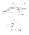
- cam follower section 29 is bent out of the plane of the slider spring 19. However, on its upper edge, said section is preferably angled inward toward the other slider spring 18. As a result of this, again two bends 36, 37 and a particularly wide edge 32 are formed. This "edge” is formed by an inward-bent section 40 of a portion of the cam follower section 29. Even in particularly fast operating modes there is no risk, whatsoever, for the edge 32 to potentially move past the corresponding guide surface 26 or narrow surface 27. Also, in this embodiment of the invention that does not enable any penetration of another knitting tool from the top, the operation is, again, clearly more reliable than in the conventional design depicted in Figure 8 .
- the slider 17 of an improved slider needle 10 comprises a slot guide 24, wherein the slider springs 18, 19 are provided with a dual deformation on their respective cam follower sections 29.
- the dual deformation is produced, for example, by a double bend and/or by an additional superficial embossing on a partial surface 34 or also by bending over a section 40 close to the edge. Due to this measure, the guiding precision of the slot guide 24 is improved and, if desired, the penetration space between the two slider springs 18, 19 is also enlarged.
Landscapes
- Chemical & Material Sciences (AREA)
- Engineering & Computer Science (AREA)
- General Chemical & Material Sciences (AREA)
- Chemical Kinetics & Catalysis (AREA)
- Materials Engineering (AREA)
- Mechanical Engineering (AREA)
- Metallurgy (AREA)
- Organic Chemistry (AREA)
- Textile Engineering (AREA)
- Knitting Machines (AREA)
- Bearings For Parts Moving Linearly (AREA)
Abstract
Description
- The invention relates to a slider needle with improved slider control.
- A slider needle has been known, for example from publication
EP 1 229 158 B1 . This slider needle has a needle body with a slider channel that is delimited by two lateral walls. The slider that comprises two leaf springs is arranged between two lateral walls. The slider can be moved in the slider channel in longitudinal direction in order to have its catch contact the hook of the needle base body and to close the interior space of the hook. When the slider is retracted it releases the hook. Its catch is then removed from the hook. When the slider is being retracted it is frequently desired that said slider perform not only a longitudinal retracting movement but, at the same time, a descending movement. To accomplish this, the bottom of the slider channel has a ramp. In order to guide the slider down the ramp, the slider has laterally bowed cam follower sections that come into engagement with slot guides of the lateral walls. The cam follower sections have cam follower surfaces that, in doing so, move along the corresponding cams of the slot guide recess. - In addition, the laterally bowed cam follower sections of the two slider springs can form a penetration funnel into which other knitting tools may descend, for example for stitch re-hanging.
- Considering the design of the slider, care must be taken that said slider will reliably descend into the slider channel, even with extremely filiform needles and at high knitting speed.
- If other knitting tools are intended to penetrate the laterally bowed cam follower sections, penetration should be made as easy as possible.
- Thus, the resultant object of the invention is to provide an improved slider needle, whereby the design of said slider needle is suitable, in particular, for the production of slider needles with a particularly fine division.
- This object is achieved with the slider needle in accordance with Claim 1:
- The slider needle in accordance with the invention has an elongated needle body with a slider channel that is delimited by two lateral walls. On its one end, the slider has two slider springs. The slider springs may be molded in one piece to a slider base body or may also be subsequently detachably or non-detachably connected with the slider shank. At least one of the two slider springs has a cam follower section that interacts with a slot guide recess provided in the adjacent lateral wall. Preferably, the other slider spring also has such a mirror-symmetrical cam follower section that also is in engagement with a slot guide recess of its associate lateral wall. In the slider needle of the invention herein, the cam follower surface provided on the cam follower section is in alignment with the guide surface of the slot guide recess.
- The alignment is preferably achieved by dual or multiple bends of the cam follower section. The alignment of the cam follower surface relative to the guide surface may be accomplished with various measures. For example, it can be ensured that the cam follower surface is aligned parallel with the slot guide surface of the slot guide recess, at least relative to the cross-sectional plane of the guide body and the slider. Additionally or alternatively, the alignment of the cam follower surface relative to the guide surface may be accomplished in that the cam follower surface does not laterally extend beyond the guide surface. In this context, the cam follower surface may have the same width as, or be narrower than, the guide surface. In particular, the alignment may also consist in that the upper part of the cam follower section, said part being directly adjacent to the cam follower surface, has an orientation that is parallel to the lateral wall relative to a vertical direction perpendicular to the slider channel bottom.
- In order to align the cam follower surface with the guide surface the laterally bowed cam follower section may be provided with an embossing or other imparted shaping. In particular, the cam follower section may display a reduced wall thickness in the embossed region. Embossing achieves a plastic deformation of the material of the cam follower section, in the course of which a (minimal) flow of the material can occur. As a result of this, the precise positioning of the cam follower surface can be achieved so that said surface is aligned relative to the slot guide recess as desired. The embossing may be visible as an indentation. The indentation may be provided on the side of the slider spring opposite the lateral wall (i.e., "outside") or also on the opposite side of the slider spring facing the other slider spring (i.e., "inside").
- The molded indentation that is visible as an indentation is preferably provided so as to directly adjoin the cam follower surface. In doing so, the desired precision of the alignment of the cam follower surface is easily achieved.
- Alternatively, the slider needle may also comprise a slider with a slider spring having a bent edge on the cam follower section. This bent edge offers a particularly wide cam follower surface, thus achieving a reliable interaction with the slot guide and the cam follower.
- The slider needle of the invention herein comprises a slider having a cam follower section that is in specific alignment with the slot guide or that has a widened guide surface. Both measures have the result that the slider is reliably guided, in particular when said slider is being retracted and is descending into the slider channel. The risk that the cam follower and the guide surface of the slot guide will miss each other laterally and the slider will thus not descend or be moved out properly has been avoided. In addition, the embodiment with the additional laterally molded indentation or embossing of the cam follower section of the slider spring can create an enlarged free space between the slider springs in the cam follower section, thus facilitating the descending of penetrating tools.
- Additional details of advantageous embodiments of the invention result from the description or the claims, and from the drawings. They show in
-
Figure 1 a schematized perspective representation of a section, indicating the basic principle of a slider needle in accordance with the invention; -
Figure 2 a side view of a detail of the slider needle as inFigure 1 ; -
Figure 3 a perspective representation of a section of the slider of the slider needle as inFigure 1 ; -
Figure 4 a plan view of a schematized section of the slider springs of the slider needle as inFigure 1 ; -
Figure 5 a vertical section of an embodiment of a slider needle in accordance with the invention; -
Figure 6 a perspective representation of a section of a slider spring of the slider needle as inFigure 5 ; -
Figure 7 a vertical section of a section of an alternative embodiment of the slider needle; -
Figure 8 a vertical section of a section of a prior-art slider needle; -
Figure 9 a perspective representation of a section of an alternative embodiment of a slider of a slider needle in accordance with the invention; and -
Figure 10 a cross-section through a slider spring of the slider as inFigure 9 . -
Figure 1 shows aslider needle 10, said needle acting as the knitting needle. Said needle has anelongated needle body 11 bearing ahook 12 on one end. The slider needle can be configured for a particularly fine division. - The
needle body 11 has aslider channel 13 that is delimited by twolateral walls slider channel 13 extends through theneedle body 11 in sliding direction L. Theslider channel 13 becomes flat as it terminates near thehook 12. On the underside, said slider channel is delimited by abottom 16 that is concealed inFigure 1 and thus indicated in a dashed line. Aslider 17 is held between the flat, preferably plane,lateral walls slider springs slider springs catch 20 on the end, said catch facing thehook 12. This catch can be moved - in sliding direction L - toward thehook 12 and away from said hook. At least in a few embodiments, theslider 17 can also be moved far enough for thehook 12 to be received between theslider springs slider needle 10. - The usual driving means of a
slider needle 10 prespecify the movement of theneedle body 11 and/or theslider 17. These driving means are not specifically shown in the figures. For example, theneedle body 10 may have one or more feet. Likewise, theslider 17 may have one or more feet. These feet interact with a cam assembly that effects a relative movement between theneedle body 11 and theslider 17. - The
slider channel 13 may additionally be closed at the top by aclosing piece 21. This closing piece is preferably a part of the slider or the slider base body. - As has already been obvious from
Figure 1 , the bottom 16 has aramp 22 that is disposed to impart theslider 17 with a vertical movement, said movement being directed perpendicularly toward the bottom 16. To accomplish this, theslider 17, or its slider springs, have aninclined surface 23, as is obvious fromFigure 3 . When theslider 17 is moved toward thehook 12, theinclined surface 23 reaches theramp 22 at some time and continues to move along said ramp. As a result of this, theslider 17 is lifted slightly. Thecatch 20 that is otherwise located below thehook 12 is guided to the level of the tip of thehook 12 meeting said hook at that point. - The
inclined surface 23 can effect a lifting, but not a secure, descending of theslider 17. In particular, if theslider channel 13 is soiled, for example, by abraded fiber and metal materials, oil, wax, Avivagen, etc., there is the risk that theslider 17 will not reliably descend. Aslot guide 24 is provided for again lowering theslider 17 in a targeted manner during retraction. Theslot guide 24 shown inFigure 1 is shown in greater detail inFigure 2 with the aid of theslider spring 19 and thelateral wall 15. Theslot guide 24 comprises aslot guide recess 25 in thelateral wall 15, said slot guide recess having aguide surface 26. Theguide surface 26 is a surface that is oriented so as to be inclined relative to the bottom 16, i.e., said guide surface is aligned approximately parallel with theramp 22. It terminates in a mouth-like recess that opens toward thehook 12. Theguide surface 26 is adjoined by a preferably straightnarrow surface 27 that is disposed to hold theslider 17 in deep position. - Beside the
slider spring 19, theslot guide 24 also comprises acam follower 28 that is configured as a laterally bowedcam follower section 29 of theslider spring 19. At abending line 30, the cam follower section terminates in theslider spring 19. The lateral bowing of theslider spring 19 on thecam follower section 29 is obvious fromFigure 3 . In doing so, the lateral bowing is large enough to enable thecam follower section 29 to extend into theslot guide recess 25 when theslider spring 17 is in retracted position. When theslider spring 17 is being retracted, an inclinedcam follower surface 31 of thecam follower section 29 initially moves along theinclined guide surface 26, whereupon an upperstraight edge 32 of thecam follower section 29 ends up under thenarrow surface 27. - In at least in one preferred embodiment, the slider springs 18, 19 are symmetrical relative to each other. The description of the
slot guide recess 25 and thecam follower section 29 hereinabove thus applies, analogously, to theslider spring 18 and thelateral wall 14. Consequently, analogous structures of theslider spring 18 are identified with the same reference sign. - As is shown by
Figures 2 and3 , theslider spring 19 is bent twice on itscam follower section 29. Theslider spring 19 has a bend at thebending line 30, said bend causing thecam follower section 29 to laterally project beyond the flat side of the bendingspring 19. A second deformation begins at aline 33, said deformation affecting apartial region 34 of thecam follower section 29. Thepartial region 34 may represent a second bend. In this case, theline 33 is a bending line. However, this may also be molded indentation that has been produced, for example, during an embossing step. In this case, theline 33 represents a sharp or rounded edge. In the exemplary embodiment ofFigures 2 and3 , the molded indentation is located on the outside of the bendingspring 17. The result of this is that thecam follower surface 31 and/or theedge 32 are slightly narrower - a least along a part of their length - than the remainder of theslider spring 19. In other words, the material thickness may be reduced in thepartial region 34. The reduction of the thickness can be visible mostly on the outside, as is being suggested byFigures 2 and3 . Additionally or alternatively, the thickness reduction may also be provided on the inside side facing theslider spring 18, as is illustrated byFigures 4 through 6 . InFigure 5 , acenter line 35 has been drawn in a chain line for the purpose of clarification, said center line identifying the bend of theslider spring 19. As is obvious, afirst bend 36 is provided on thebending line 30. Beginning at that point, thecenter line 35 branches out of the orientation parallel to thelateral wall 15 into an orientation that is at an acute angle relative to thelateral wall 15. At a bending point, or also gradually, thecenter line 35 may terminate in another angle in asecond bend 37. For example, in this instance, thecenter line 35 may again extend parallel to the lateral wall. To make this better understandable, the center of thelateral wall 15 is marked by acenter line 38, said center line being drawn as a chain line. - If the
cam follower section 29 is provided in thepartial region 34 adjacent to theedge 32 with an embossing or molded indentation, thecenter line 35 displays an additional, in this instance third,bend 39 at the start of this molded indentation. Thus, thecenter line 35 can be offset at theedge 32 relative to thecenter line 38. However, in a preferred embodiment, theedge 32 at least does not laterally project beyond thenarrow surface 27. - During operation, the
slider 17 is moved in a reciprocating manner. In doing so, when theslider 17 is being retracted, the cam follower surfaces 31 of the two slider springs 18, 19 come into contact with thenarrow surfaces 27 of the slot guide recesses 25. Due to the inclined position of the surfaces, theslider 17 is displaced downward in the direction toward the bottom 16 when said slider is retracted further. Due to the alignment of theedge 32 and thecam follower surface 31 relative to thenarrow surface 27 and theguide surface 26, it is ensured that the surfaces move on each other in a precise manner. Thecam follower surface 31 is prevented from moving past theguide surface 26 or from sliding off said guide surface. In other words, even in the case of particularly filiform needle designs and at high operating speed, the full functionality of theslot guide 24 is ensured, even when the slider needle is soiled. - As is shown in
Figure 7 , the sections of thecam follower section 29 may also have a more or less uniform thicknesses. However, thecenter line 35 is provided with twobends center line 38 in thepartial region 34. Even if theedge 32 and/or thecam follower surface 31 extending laterally somewhat next to thenarrow surface 27, i.e., extend beyond said narrow surface, any sliding-off is reliably prevented. - The relationships are usually different when the slider spring 19' has only a
single bend 36, as is common in prior art as depicted inFigure 8 . In this case, the edge 32' is not in alignment with the narrow surface 27'. Rather, they extend at an acute angle with respect to each other. In high-speed mode, the slider spring 19' can slip off the narrow surface 27' of the lateral wall 15', so that the full functionality of the slot guide 24' in accordance with prior art cannot be ensured. - As can be seen, the
bends 36, 37 (and, if necessary, bend 39) are matched in such a manner that theedge 32 and thenarrow surface 37 are aligned with each other in a matching manner. For example, this is obvious from the fact that the part of thecenter line 35 adjacent theedge 32 is oriented parallel (or substantially parallel) to thecenter line 38. In the exemplary embodiment ofFigure 7 , thebends bends slider spring 19 or thepartial region 34. -
Figure 9 shows a greatly modified embodiment of theslider 17 of theslider needle 10 of the invention herein. Again, the slider springs 18, 19 are configured so as to be mirror-symmetrical. Consequently, the description hereinafter equally applies to both slider springs 18, 19. - Again, the
cam follower section 29 is bent out of the plane of theslider spring 19. However, on its upper edge, said section is preferably angled inward toward theother slider spring 18. As a result of this, again twobends wide edge 32 are formed. This "edge" is formed by an inward-bent section 40 of a portion of thecam follower section 29. Even in particularly fast operating modes there is no risk, whatsoever, for theedge 32 to potentially move past the correspondingguide surface 26 ornarrow surface 27. Also, in this embodiment of the invention that does not enable any penetration of another knitting tool from the top, the operation is, again, clearly more reliable than in the conventional design depicted inFigure 8 . - The
slider 17 of animproved slider needle 10 comprises aslot guide 24, wherein the slider springs 18, 19 are provided with a dual deformation on their respectivecam follower sections 29. The dual deformation is produced, for example, by a double bend and/or by an additional superficial embossing on apartial surface 34 or also by bending over asection 40 close to the edge. Due to this measure, the guiding precision of theslot guide 24 is improved and, if desired, the penetration space between the two slider springs 18, 19 is also enlarged. -
- 10
- Slider needle
- 11
- Needle body
- 12
- Hook
- 13
- Slider channel
- 14
- Lateral wall
- 15, 15'
- Lateral wall
- 16
- Bottom
- 17
- Slider
- 18
- Slider spring
- 19, 19'
- Slider spring
- 20
- Catch
- 21
- Closing piece
- 22
- Ramp
- 23
- Inclined surface
- 24, 24'
- Slot guide
- 25
- Slot guide recess
- 26
- Guide surface
- 27, 27'
- Narrow surface
- 28
- Cam follower
- 29
- Cam follower section
- 30
- Bending line
- 31
- Cam follower surface
- 32, 32'
- Edge
- 33
- Line
- 34
- Partial region
- 35
- Center line
- 36
- First bend
- 37
- Second bend
- 38
- Center line
- 39
- Third bend
- 40
- Section
- L
- Sliding direction
Claims (15)
- Slider needle (10)
having an elongated needle body (11) with two oppositely located lateral walls (18, 19) and having a slider channel (13) that is delimited by a bottom (16), and
having a slider (17) that is arranged in the slider channel (13) so that it can be slid along a sliding direction (L),and that comprises two flat slider springs (18, 19),
whereby at least one of the lateral walls (14, 15) has a slot guide recess (25) with a guide surface (26), and whereby the slider spring (19), at least in retracted state of the lateral wall (15), has a laterally bowed cam follower section (29) with a cam follower surface (31), said cam follower section being associated with the slot guide recess (25),
whereby the cam follower section (29) has two or more deformations (36, 37, 39). - Slider needle as in Claim 1, characterized in that the cam follower surface (31) and the guide surface (26) are aligned parallel with each other in order to center them relative to each other in a cutting plane, whereby the sliding direction (L) is perpendicular to said cutting plane.
- Slider needle as in Claim 1, characterized in that the cam follower surface (31) and the guide surface (26) are aligned fully overlapping each other in order to center them relative to each other in a cutting plane, whereby the sliding direction (L) is perpendicular to said cutting plane.
- Slider needle as in Claim 1, 2 or 3, characterized in that the partial region (34) of the laterally bowed cam follower section (29) of the slider spring (19), said partial region being adjacent to the cam follower surface (31), is oriented parallel with the lateral wall (15).
- Slider needle as in Claim 1, characterized in that the laterally bowed cam follower section (29) of the slider spring (19) is provided with a molded indentation.
- Slider needle as in Claim 1, characterized in that the molded indentation is provided on the side of the slider spring (19), said side facing the other slider spring (18).
- Slider needle as in Claim 5, characterized in that the molded indentation is provided on the side of the slider spring (19), said side facing away from the other slider spring (18).
- Slider needle as in Claim 1, characterized in that the slider spring (19) has a reduced wall thickness in at least a portion of the bowed cam follower section (29).
- Slider needle as in Claim 5, characterized in that the molded indentation is adjacent to the cam follower surface (31).
- Slider needle as in Claim 1, characterized in that the lateral cam follower section (29) is separated from the slider spring (17) by at least one recess.
- Slider needle as in Claim 1, characterized in that the slider spring (19) has a thickness that matches the thickness of the lateral wall (15).
- Slider needle as in Claim 1, characterized in that the cam follower section (29) has a thickness that matches the thickness of the lateral wall (15).
- Slider needle as in Claim 1, characterized in that the dual or multiple deformation of the cam follower section (29) is represented by dual or multiple bends.
- Slider needle as in Claim 1, characterized in that the cam follower section (29) has a bent-over section (40) where the cam follower surface (31, 32) is provided.
- Slider needle as in Claim 14, characterized in that the width of the cam follower surface (31) is greater than the wall thickness of the lateral wall (15).
Priority Applications (8)
| Application Number | Priority Date | Filing Date | Title |
|---|---|---|---|
| PT111849170T PT2581480T (en) | 2011-10-12 | 2011-10-12 | Slider needle with improved slider |
| TR2018/09022T TR201809022T4 (en) | 2011-10-12 | 2011-10-12 | Sliding needle with improved slide. |
| EP11184917.0A EP2581480B1 (en) | 2011-10-12 | 2011-10-12 | Slider needle with improved slider |
| JP2012195096A JP6059856B2 (en) | 2011-10-12 | 2012-09-05 | Slider needle with improved slider |
| TW101137383A TWI586862B (en) | 2011-10-12 | 2012-10-11 | Slider needle with improved slider |
| KR1020120112819A KR101970121B1 (en) | 2011-10-12 | 2012-10-11 | Slider needle with improved slider |
| CN201210383329.1A CN103046220B (en) | 2011-10-12 | 2012-10-11 | There is the saddle knitting needle improving saddle |
| US13/649,207 US8578740B2 (en) | 2011-10-12 | 2012-10-11 | Slider needle with improved slider |
Applications Claiming Priority (1)
| Application Number | Priority Date | Filing Date | Title |
|---|---|---|---|
| EP11184917.0A EP2581480B1 (en) | 2011-10-12 | 2011-10-12 | Slider needle with improved slider |
Publications (2)
| Publication Number | Publication Date |
|---|---|
| EP2581480A1 true EP2581480A1 (en) | 2013-04-17 |
| EP2581480B1 EP2581480B1 (en) | 2018-05-30 |
Family
ID=44862540
Family Applications (1)
| Application Number | Title | Priority Date | Filing Date |
|---|---|---|---|
| EP11184917.0A Active EP2581480B1 (en) | 2011-10-12 | 2011-10-12 | Slider needle with improved slider |
Country Status (8)
| Country | Link |
|---|---|
| US (1) | US8578740B2 (en) |
| EP (1) | EP2581480B1 (en) |
| JP (1) | JP6059856B2 (en) |
| KR (1) | KR101970121B1 (en) |
| CN (1) | CN103046220B (en) |
| PT (1) | PT2581480T (en) |
| TR (1) | TR201809022T4 (en) |
| TW (1) | TWI586862B (en) |
Cited By (2)
| Publication number | Priority date | Publication date | Assignee | Title |
|---|---|---|---|---|
| DE102015105648A1 (en) | 2015-04-14 | 2016-10-20 | Groz-Beckert Kg | Slide spring, slide, slide needle, guide arrangement and method for producing at least one slide spring |
| EP3904578A1 (en) * | 2020-04-29 | 2021-11-03 | Groz-Beckert KG | Compound needle for knitting machines |
Families Citing this family (2)
| Publication number | Priority date | Publication date | Assignee | Title |
|---|---|---|---|---|
| DE102013105239A1 (en) * | 2013-05-22 | 2014-11-27 | Groz-Beckert Kg | needle |
| JP6692325B2 (en) * | 2017-07-07 | 2020-05-13 | 株式会社島精機製作所 | Compound needle |
Citations (2)
| Publication number | Priority date | Publication date | Assignee | Title |
|---|---|---|---|---|
| EP1229158A1 (en) * | 1999-10-27 | 2002-08-07 | Shima Seiki Mfg., Ltd | Guide mechanism of knitting member and compound needle assembling the guide mechanism therein |
| EP2458052A2 (en) * | 2010-11-22 | 2012-05-30 | Shima Seiki Mfg., Ltd | Compound needle for flatbed knitting machine |
Family Cites Families (15)
| Publication number | Priority date | Publication date | Assignee | Title |
|---|---|---|---|---|
| US1673634A (en) * | 1927-05-25 | 1928-06-12 | Scott & Williams Inc | Knitting-machine needle |
| US3584481A (en) * | 1969-03-06 | 1971-06-15 | Teihichi Kayashi | Knitting needle for transferring stitches |
| JPH0578962A (en) * | 1991-09-17 | 1993-03-30 | Shima Seiki Mfg Ltd | Compound needle for knitting machine |
| JP3554094B2 (en) * | 1995-12-12 | 2004-08-11 | 株式会社島精機製作所 | Composite needle with transfer function |
| US5937673A (en) * | 1997-05-01 | 1999-08-17 | Shima Seiki Manufacturing, Ltd. | Compound needle of a flat knitting machine |
| DE19913822C2 (en) | 1999-03-26 | 2001-02-22 | Groz Beckert Kg | Slide needle with split slide |
| JP3379947B2 (en) * | 1999-04-15 | 2003-02-24 | 株式会社島精機製作所 | Composite needle of knitting machine |
| JP3538730B2 (en) * | 1999-05-19 | 2004-06-14 | 株式会社島精機製作所 | Composite knitting needle |
| US6904774B2 (en) * | 2000-10-20 | 2005-06-14 | Shima Seiki Mfg., Ltd. | Composite needs |
| DE10130364C1 (en) * | 2001-06-23 | 2003-02-13 | Groz Beckert Kg | needle |
| DE10130365C1 (en) * | 2001-06-23 | 2003-01-23 | Groz Beckert Kg | Slider needle with improved slider |
| DE60229537D1 (en) * | 2001-08-24 | 2008-12-04 | Shima Seiki Mfg | COMPOSITE NEEDLE FOR KNITTING MACHINE |
| KR101062665B1 (en) * | 2002-12-20 | 2011-09-06 | 가부시키가이샤 시마세이키 세이사쿠쇼 | Compound Needle |
| EP2072649B1 (en) * | 2007-12-20 | 2011-10-19 | Groz-Beckert KG | Take-off cam part |
| EP2305868B1 (en) * | 2009-09-30 | 2012-11-21 | Groz-Beckert KG | Sliding needle with built-in partition wall |
-
2011
- 2011-10-12 TR TR2018/09022T patent/TR201809022T4/en unknown
- 2011-10-12 PT PT111849170T patent/PT2581480T/en unknown
- 2011-10-12 EP EP11184917.0A patent/EP2581480B1/en active Active
-
2012
- 2012-09-05 JP JP2012195096A patent/JP6059856B2/en active Active
- 2012-10-11 TW TW101137383A patent/TWI586862B/en active
- 2012-10-11 US US13/649,207 patent/US8578740B2/en active Active
- 2012-10-11 KR KR1020120112819A patent/KR101970121B1/en active Active
- 2012-10-11 CN CN201210383329.1A patent/CN103046220B/en active Active
Patent Citations (3)
| Publication number | Priority date | Publication date | Assignee | Title |
|---|---|---|---|---|
| EP1229158A1 (en) * | 1999-10-27 | 2002-08-07 | Shima Seiki Mfg., Ltd | Guide mechanism of knitting member and compound needle assembling the guide mechanism therein |
| EP1229158B1 (en) | 1999-10-27 | 2006-10-18 | Shima Seiki Mfg., Ltd | Guide mechanism of knitting member and compound needle assembling the guide mechanism therein |
| EP2458052A2 (en) * | 2010-11-22 | 2012-05-30 | Shima Seiki Mfg., Ltd | Compound needle for flatbed knitting machine |
Cited By (12)
| Publication number | Priority date | Publication date | Assignee | Title |
|---|---|---|---|---|
| DE102015105648A1 (en) | 2015-04-14 | 2016-10-20 | Groz-Beckert Kg | Slide spring, slide, slide needle, guide arrangement and method for producing at least one slide spring |
| WO2016165991A1 (en) | 2015-04-14 | 2016-10-20 | Groz-Beckert Kg | Slide spring, slide, slide needle, guide arrangement, and method for producing at least one slide spring |
| CN107636218A (en) * | 2015-04-14 | 2018-01-26 | 格罗茨-贝克特公司 | Sliding block spring, sliding block, sliding needle, guide device and the method for manufacturing at least one sliding block spring |
| KR20180027406A (en) * | 2015-04-14 | 2018-03-14 | 그로츠-베케르트 카게 | Slide spring, slide, slide needle, guide arrangement, and method for producing at least one slide spring |
| US10364519B2 (en) | 2015-04-14 | 2019-07-30 | Groz-Beckert Kg | Slide spring, slide, slide needle, guide arrangement, and method for producing at least one slide spring |
| EP3904578A1 (en) * | 2020-04-29 | 2021-11-03 | Groz-Beckert KG | Compound needle for knitting machines |
| WO2021219261A1 (en) | 2020-04-29 | 2021-11-04 | Groz-Beckert Kg | Slide needle for knitting machines |
| KR20220130238A (en) * | 2020-04-29 | 2022-09-26 | 그로츠-베케르트 카게 | Composite needles for knitting machines |
| CN115398052A (en) * | 2020-04-29 | 2022-11-25 | 格罗兹-贝克特公司 | Sliding needle for knitting machine |
| CN115398052B (en) * | 2020-04-29 | 2023-12-15 | 格罗兹-贝克特公司 | Sliding needle for knitting machine |
| US11891734B2 (en) | 2020-04-29 | 2024-02-06 | Groz-Beckert Kg | Compound needle for knitting machines |
| TWI896620B (en) * | 2020-04-29 | 2025-09-11 | 德商葛羅斯貝克公司 | Compound needles for knitting machines |
Also Published As
| Publication number | Publication date |
|---|---|
| KR101970121B1 (en) | 2019-04-19 |
| KR20130039695A (en) | 2013-04-22 |
| JP2013083033A (en) | 2013-05-09 |
| JP6059856B2 (en) | 2017-01-11 |
| US8578740B2 (en) | 2013-11-12 |
| US20130091901A1 (en) | 2013-04-18 |
| TR201809022T4 (en) | 2018-07-23 |
| TWI586862B (en) | 2017-06-11 |
| EP2581480B1 (en) | 2018-05-30 |
| TW201333293A (en) | 2013-08-16 |
| PT2581480T (en) | 2018-07-04 |
| CN103046220A (en) | 2013-04-17 |
| CN103046220B (en) | 2016-07-06 |
Similar Documents
| Publication | Publication Date | Title |
|---|---|---|
| EP2581480B1 (en) | Slider needle with improved slider | |
| US7117694B2 (en) | System component having a braking spring | |
| EP2063009A1 (en) | Sinker for a knitting system and knitting system showing reduced wear | |
| KR102355649B1 (en) | Knitting tool for knitting machines | |
| KR20180033284A (en) | Method of forming loops, devices, and system components | |
| JP3983737B2 (en) | Compound needle of knitting machine | |
| KR102573448B1 (en) | Slide spring, slide, slide needle, guide arrangement, and method for producing at least one slide spring | |
| US7836729B2 (en) | Transfer needle with internal spring tip | |
| JP4125324B2 (en) | Cutting needle | |
| CN101597836A (en) | The knocking-over sinker that knitting needle drives | |
| US7509820B2 (en) | Latch-type needle for stitch-forming textile machine | |
| KR101569012B1 (en) | Flatbed knitting machine provided with movable sinker | |
| EP2551393B1 (en) | Complex needle, weft knitting machine | |
| KR100821867B1 (en) | Compound needle | |
| US7334436B2 (en) | Component for a knitting system | |
| CN102046868B (en) | Knitting needle | |
| US5987932A (en) | Slider type needle for knitting machine | |
| JP2003055869A (en) | Slide needles especially for stitch forming textile machines | |
| JP5232862B2 (en) | Pusher for stitch movement in circular sock knitting machines | |
| HK1230677A1 (en) | Knitting tool for knitting machines | |
| HK1216909A1 (en) | Slide needle |
Legal Events
| Date | Code | Title | Description |
|---|---|---|---|
| PUAI | Public reference made under article 153(3) epc to a published international application that has entered the european phase |
Free format text: ORIGINAL CODE: 0009012 |
|
| AK | Designated contracting states |
Kind code of ref document: A1 Designated state(s): AL AT BE BG CH CY CZ DE DK EE ES FI FR GB GR HR HU IE IS IT LI LT LU LV MC MK MT NL NO PL PT RO RS SE SI SK SM TR |
|
| AX | Request for extension of the european patent |
Extension state: BA ME |
|
| 17P | Request for examination filed |
Effective date: 20130527 |
|
| RBV | Designated contracting states (corrected) |
Designated state(s): AL AT BE BG CH CY CZ DE DK EE ES FI FR GB GR HR HU IE IS IT LI LT LU LV MC MK MT NL NO PL PT RO RS SE SI SK SM TR |
|
| RIC1 | Information provided on ipc code assigned before grant |
Ipc: D04B 35/06 20060101AFI20171129BHEP |
|
| GRAP | Despatch of communication of intention to grant a patent |
Free format text: ORIGINAL CODE: EPIDOSNIGR1 |
|
| STAA | Information on the status of an ep patent application or granted ep patent |
Free format text: STATUS: GRANT OF PATENT IS INTENDED |
|
| INTG | Intention to grant announced |
Effective date: 20180109 |
|
| GRAS | Grant fee paid |
Free format text: ORIGINAL CODE: EPIDOSNIGR3 |
|
| GRAA | (expected) grant |
Free format text: ORIGINAL CODE: 0009210 |
|
| STAA | Information on the status of an ep patent application or granted ep patent |
Free format text: STATUS: THE PATENT HAS BEEN GRANTED |
|
| AK | Designated contracting states |
Kind code of ref document: B1 Designated state(s): AL AT BE BG CH CY CZ DE DK EE ES FI FR GB GR HR HU IE IS IT LI LT LU LV MC MK MT NL NO PL PT RO RS SE SI SK SM TR |
|
| REG | Reference to a national code |
Ref country code: GB Ref legal event code: FG4D |
|
| REG | Reference to a national code |
Ref country code: CH Ref legal event code: EP |
|
| REG | Reference to a national code |
Ref country code: AT Ref legal event code: REF Ref document number: 1003713 Country of ref document: AT Kind code of ref document: T Effective date: 20180615 |
|
| REG | Reference to a national code |
Ref country code: RO Ref legal event code: EPE |
|
| REG | Reference to a national code |
Ref country code: IE Ref legal event code: FG4D |
|
| REG | Reference to a national code |
Ref country code: DE Ref legal event code: R096 Ref document number: 602011048735 Country of ref document: DE |
|
| REG | Reference to a national code |
Ref country code: PT Ref legal event code: SC4A Ref document number: 2581480 Country of ref document: PT Date of ref document: 20180704 Kind code of ref document: T Free format text: AVAILABILITY OF NATIONAL TRANSLATION Effective date: 20180627 |
|
| REG | Reference to a national code |
Ref country code: NL Ref legal event code: MP Effective date: 20180530 |
|
| REG | Reference to a national code |
Ref country code: LT Ref legal event code: MG4D |
|
| PG25 | Lapsed in a contracting state [announced via postgrant information from national office to epo] |
Ref country code: CY Free format text: LAPSE BECAUSE OF FAILURE TO SUBMIT A TRANSLATION OF THE DESCRIPTION OR TO PAY THE FEE WITHIN THE PRESCRIBED TIME-LIMIT Effective date: 20180530 Ref country code: LT Free format text: LAPSE BECAUSE OF FAILURE TO SUBMIT A TRANSLATION OF THE DESCRIPTION OR TO PAY THE FEE WITHIN THE PRESCRIBED TIME-LIMIT Effective date: 20180530 Ref country code: NO Free format text: LAPSE BECAUSE OF FAILURE TO SUBMIT A TRANSLATION OF THE DESCRIPTION OR TO PAY THE FEE WITHIN THE PRESCRIBED TIME-LIMIT Effective date: 20180830 Ref country code: SE Free format text: LAPSE BECAUSE OF FAILURE TO SUBMIT A TRANSLATION OF THE DESCRIPTION OR TO PAY THE FEE WITHIN THE PRESCRIBED TIME-LIMIT Effective date: 20180530 Ref country code: ES Free format text: LAPSE BECAUSE OF FAILURE TO SUBMIT A TRANSLATION OF THE DESCRIPTION OR TO PAY THE FEE WITHIN THE PRESCRIBED TIME-LIMIT Effective date: 20180530 Ref country code: FI Free format text: LAPSE BECAUSE OF FAILURE TO SUBMIT A TRANSLATION OF THE DESCRIPTION OR TO PAY THE FEE WITHIN THE PRESCRIBED TIME-LIMIT Effective date: 20180530 Ref country code: BG Free format text: LAPSE BECAUSE OF FAILURE TO SUBMIT A TRANSLATION OF THE DESCRIPTION OR TO PAY THE FEE WITHIN THE PRESCRIBED TIME-LIMIT Effective date: 20180830 |
|
| PG25 | Lapsed in a contracting state [announced via postgrant information from national office to epo] |
Ref country code: LV Free format text: LAPSE BECAUSE OF FAILURE TO SUBMIT A TRANSLATION OF THE DESCRIPTION OR TO PAY THE FEE WITHIN THE PRESCRIBED TIME-LIMIT Effective date: 20180530 Ref country code: RS Free format text: LAPSE BECAUSE OF FAILURE TO SUBMIT A TRANSLATION OF THE DESCRIPTION OR TO PAY THE FEE WITHIN THE PRESCRIBED TIME-LIMIT Effective date: 20180530 Ref country code: GR Free format text: LAPSE BECAUSE OF FAILURE TO SUBMIT A TRANSLATION OF THE DESCRIPTION OR TO PAY THE FEE WITHIN THE PRESCRIBED TIME-LIMIT Effective date: 20180831 Ref country code: HR Free format text: LAPSE BECAUSE OF FAILURE TO SUBMIT A TRANSLATION OF THE DESCRIPTION OR TO PAY THE FEE WITHIN THE PRESCRIBED TIME-LIMIT Effective date: 20180530 |
|
| REG | Reference to a national code |
Ref country code: AT Ref legal event code: MK05 Ref document number: 1003713 Country of ref document: AT Kind code of ref document: T Effective date: 20180530 |
|
| PG25 | Lapsed in a contracting state [announced via postgrant information from national office to epo] |
Ref country code: NL Free format text: LAPSE BECAUSE OF FAILURE TO SUBMIT A TRANSLATION OF THE DESCRIPTION OR TO PAY THE FEE WITHIN THE PRESCRIBED TIME-LIMIT Effective date: 20180530 |
|
| PG25 | Lapsed in a contracting state [announced via postgrant information from national office to epo] |
Ref country code: AT Free format text: LAPSE BECAUSE OF FAILURE TO SUBMIT A TRANSLATION OF THE DESCRIPTION OR TO PAY THE FEE WITHIN THE PRESCRIBED TIME-LIMIT Effective date: 20180530 Ref country code: DK Free format text: LAPSE BECAUSE OF FAILURE TO SUBMIT A TRANSLATION OF THE DESCRIPTION OR TO PAY THE FEE WITHIN THE PRESCRIBED TIME-LIMIT Effective date: 20180530 Ref country code: EE Free format text: LAPSE BECAUSE OF FAILURE TO SUBMIT A TRANSLATION OF THE DESCRIPTION OR TO PAY THE FEE WITHIN THE PRESCRIBED TIME-LIMIT Effective date: 20180530 Ref country code: PL Free format text: LAPSE BECAUSE OF FAILURE TO SUBMIT A TRANSLATION OF THE DESCRIPTION OR TO PAY THE FEE WITHIN THE PRESCRIBED TIME-LIMIT Effective date: 20180530 Ref country code: SK Free format text: LAPSE BECAUSE OF FAILURE TO SUBMIT A TRANSLATION OF THE DESCRIPTION OR TO PAY THE FEE WITHIN THE PRESCRIBED TIME-LIMIT Effective date: 20180530 Ref country code: CZ Free format text: LAPSE BECAUSE OF FAILURE TO SUBMIT A TRANSLATION OF THE DESCRIPTION OR TO PAY THE FEE WITHIN THE PRESCRIBED TIME-LIMIT Effective date: 20180530 |
|
| PG25 | Lapsed in a contracting state [announced via postgrant information from national office to epo] |
Ref country code: SM Free format text: LAPSE BECAUSE OF FAILURE TO SUBMIT A TRANSLATION OF THE DESCRIPTION OR TO PAY THE FEE WITHIN THE PRESCRIBED TIME-LIMIT Effective date: 20180530 |
|
| REG | Reference to a national code |
Ref country code: DE Ref legal event code: R097 Ref document number: 602011048735 Country of ref document: DE |
|
| PLBE | No opposition filed within time limit |
Free format text: ORIGINAL CODE: 0009261 |
|
| STAA | Information on the status of an ep patent application or granted ep patent |
Free format text: STATUS: NO OPPOSITION FILED WITHIN TIME LIMIT |
|
| 26N | No opposition filed |
Effective date: 20190301 |
|
| PG25 | Lapsed in a contracting state [announced via postgrant information from national office to epo] |
Ref country code: SI Free format text: LAPSE BECAUSE OF FAILURE TO SUBMIT A TRANSLATION OF THE DESCRIPTION OR TO PAY THE FEE WITHIN THE PRESCRIBED TIME-LIMIT Effective date: 20180530 |
|
| REG | Reference to a national code |
Ref country code: CH Ref legal event code: PL |
|
| REG | Reference to a national code |
Ref country code: BE Ref legal event code: MM Effective date: 20181031 |
|
| PG25 | Lapsed in a contracting state [announced via postgrant information from national office to epo] |
Ref country code: MC Free format text: LAPSE BECAUSE OF FAILURE TO SUBMIT A TRANSLATION OF THE DESCRIPTION OR TO PAY THE FEE WITHIN THE PRESCRIBED TIME-LIMIT Effective date: 20180530 Ref country code: LU Free format text: LAPSE BECAUSE OF NON-PAYMENT OF DUE FEES Effective date: 20181012 |
|
| REG | Reference to a national code |
Ref country code: IE Ref legal event code: MM4A |
|
| PG25 | Lapsed in a contracting state [announced via postgrant information from national office to epo] |
Ref country code: CH Free format text: LAPSE BECAUSE OF NON-PAYMENT OF DUE FEES Effective date: 20181031 Ref country code: LI Free format text: LAPSE BECAUSE OF NON-PAYMENT OF DUE FEES Effective date: 20181031 Ref country code: FR Free format text: LAPSE BECAUSE OF NON-PAYMENT OF DUE FEES Effective date: 20181031 Ref country code: BE Free format text: LAPSE BECAUSE OF NON-PAYMENT OF DUE FEES Effective date: 20181031 |
|
| PG25 | Lapsed in a contracting state [announced via postgrant information from national office to epo] |
Ref country code: IE Free format text: LAPSE BECAUSE OF NON-PAYMENT OF DUE FEES Effective date: 20181012 |
|
| PG25 | Lapsed in a contracting state [announced via postgrant information from national office to epo] |
Ref country code: AL Free format text: LAPSE BECAUSE OF FAILURE TO SUBMIT A TRANSLATION OF THE DESCRIPTION OR TO PAY THE FEE WITHIN THE PRESCRIBED TIME-LIMIT Effective date: 20180530 |
|
| PG25 | Lapsed in a contracting state [announced via postgrant information from national office to epo] |
Ref country code: MT Free format text: LAPSE BECAUSE OF NON-PAYMENT OF DUE FEES Effective date: 20181012 |
|
| PG25 | Lapsed in a contracting state [announced via postgrant information from national office to epo] |
Ref country code: MK Free format text: LAPSE BECAUSE OF NON-PAYMENT OF DUE FEES Effective date: 20180530 Ref country code: HU Free format text: LAPSE BECAUSE OF FAILURE TO SUBMIT A TRANSLATION OF THE DESCRIPTION OR TO PAY THE FEE WITHIN THE PRESCRIBED TIME-LIMIT; INVALID AB INITIO Effective date: 20111012 |
|
| PG25 | Lapsed in a contracting state [announced via postgrant information from national office to epo] |
Ref country code: IS Free format text: LAPSE BECAUSE OF FAILURE TO SUBMIT A TRANSLATION OF THE DESCRIPTION OR TO PAY THE FEE WITHIN THE PRESCRIBED TIME-LIMIT Effective date: 20180930 |
|
| PGFP | Annual fee paid to national office [announced via postgrant information from national office to epo] |
Ref country code: IT Payment date: 20250922 Year of fee payment: 15 |
|
| PGFP | Annual fee paid to national office [announced via postgrant information from national office to epo] |
Ref country code: GB Payment date: 20250904 Year of fee payment: 15 |
|
| PGFP | Annual fee paid to national office [announced via postgrant information from national office to epo] |
Ref country code: RO Payment date: 20250922 Year of fee payment: 15 |
|
| PGFP | Annual fee paid to national office [announced via postgrant information from national office to epo] |
Ref country code: PT Payment date: 20251009 Year of fee payment: 15 |
|
| PGFP | Annual fee paid to national office [announced via postgrant information from national office to epo] |
Ref country code: DE Payment date: 20251031 Year of fee payment: 15 |
|
| PGFP | Annual fee paid to national office [announced via postgrant information from national office to epo] |
Ref country code: TR Payment date: 20251003 Year of fee payment: 15 |