EP2581316A1 - Seamless can body - Google Patents
Seamless can body Download PDFInfo
- Publication number
- EP2581316A1 EP2581316A1 EP11792286.4A EP11792286A EP2581316A1 EP 2581316 A1 EP2581316 A1 EP 2581316A1 EP 11792286 A EP11792286 A EP 11792286A EP 2581316 A1 EP2581316 A1 EP 2581316A1
- Authority
- EP
- European Patent Office
- Prior art keywords
- seamless
- center panel
- annular concave
- concave portion
- flatness
- Prior art date
- Legal status (The legal status is an assumption and is not a legal conclusion. Google has not performed a legal analysis and makes no representation as to the accuracy of the status listed.)
- Granted
Links
Images
Classifications
-
- B—PERFORMING OPERATIONS; TRANSPORTING
- B65—CONVEYING; PACKING; STORING; HANDLING THIN OR FILAMENTARY MATERIAL
- B65D—CONTAINERS FOR STORAGE OR TRANSPORT OF ARTICLES OR MATERIALS, e.g. BAGS, BARRELS, BOTTLES, BOXES, CANS, CARTONS, CRATES, DRUMS, JARS, TANKS, HOPPERS, FORWARDING CONTAINERS; ACCESSORIES, CLOSURES, OR FITTINGS THEREFOR; PACKAGING ELEMENTS; PACKAGES
- B65D1/00—Rigid or semi-rigid containers having bodies formed in one piece, e.g. by casting metallic material, by moulding plastics, by blowing vitreous material, by throwing ceramic material, by moulding pulped fibrous material or by deep-drawing operations performed on sheet material
- B65D1/12—Cans, casks, barrels, or drums
- B65D1/14—Cans, casks, barrels, or drums characterised by shape
- B65D1/16—Cans, casks, barrels, or drums characterised by shape of curved cross-section, e.g. cylindrical
- B65D1/165—Cylindrical cans
-
- B—PERFORMING OPERATIONS; TRANSPORTING
- B65—CONVEYING; PACKING; STORING; HANDLING THIN OR FILAMENTARY MATERIAL
- B65D—CONTAINERS FOR STORAGE OR TRANSPORT OF ARTICLES OR MATERIALS, e.g. BAGS, BARRELS, BOTTLES, BOXES, CANS, CARTONS, CRATES, DRUMS, JARS, TANKS, HOPPERS, FORWARDING CONTAINERS; ACCESSORIES, CLOSURES, OR FITTINGS THEREFOR; PACKAGING ELEMENTS; PACKAGES
- B65D25/00—Details of other kinds or types of rigid or semi-rigid containers
- B65D25/14—Linings or internal coatings
Definitions
- the present invention relates to a seamless can body and particularly to a seamless can body having a flat center panel at a can bottom.
- an internal pressure test method for testing whether an internal pressure is appropriate by measuring a displacement amount in the axial direction of a center panel of a negative-pressure can formed by forming the center panel of a can bottom of a seamless can body into a flat shape and filling content into the seamless can body and sealing the can body or a slightly-positive-pressure can formed by filling and sealing the can after replacing a head space with inert gas such as nitrogen in order to reduce thickness of the seamless can body or an internal pressure test method (called a tapping inspection) for testing whether internal pressure is appropriate by applying an electromagnetic shock to the center panel and measuring a tapping inspection sound (resonance frequency).
- a tapping inspection an internal pressure test method for testing whether internal pressure is appropriate by applying an electromagnetic shock to the center panel and measuring a tapping inspection sound (resonance frequency).
- the flatness of the center panel is defined by a distance of outward or inward bulging of a center portion of the center panel with respect to an outer peripheral end of the center panel as a basis surface (referred to as "bottom sink difference (BSD)", in general).
- BSD bottom sink difference
- the BSD is influenced by characteristics of metal materials and various forming conditions and is also influenced, in a case of a seamless can body obtained by drawing/ironing or wall-thinning drawing (stretch drawing)/ironing, by assist air pressure for removing the can body from a punch after the ironing and therefore it is difficult to control the flatness in such a range that the can body can be adapted to the above-described inner pressure test (see Patent Document 2).
- the can bottom of the seamless can body is formed by a punch and a bottom die corresponding to a shape of the can bottom at the time of the above-described ironing (when the ironing is finished).
- a radius R of an inner curvature of the corner portion near the annular concave portion of the can bottom is formed to be as small as 0.5 mm to 1.5 mm.
- an excessive tensile load is applied to the corner portion or a portion near the corner portion during forming of the can bottom by using the punch and the bottom die to cause constriction of thickness (decrease in thickness) at a portion in a circumferential direction of the corner portion and therefore the tensile load applied to the center panel becomes non-uniform in the circumferential direction.
- the flatness of the center panel is impaired and a decrease rate of the thickness of the annular concave portion increases to cause a crack or a cut. Such phenomena become noticeable especially when the seamless can body is made thin-walled.
- a seamless can body formed by using a covered metal plate obtained by covering a metal plate made of aluminum, tin, tin-free steel, or the like with a resin film made of polyester resin or the like the resin film of the corner portion may be damaged due to a small radius of curvature of the corner portion.
- the damage is caused on the inner surface of the seamless can body, the content deterioration in flavor or corrosion or the like occurs due to exposure of a metal face.
- the present invention has been made with these problems in the prior art in view and its object is to provide a seamless can body having suitability for the internal pressure test, excellent in formability or the like, and excellent in pressure resistance or the like in retort sterilization.
- the present inventors have achieved the present invention by taking note of facts that a radius of curvature of a corner portion provided between an inner peripheral side of an annular concave portion protruding to an inside of the can and a flat center panel on a can bottom has a major impact on flatness of the center panel and formability and that variation in the flatness of the center panel is evened out to be able to obtain a seamless can body excellent in suitability for the internal pressure test and formability by setting the radius of curvature to an appropriate value.
- a seamless can body having a can bottom shape comprising: a rim portion protruding to an outside of the can; an annular concave portion adjacent to an inner side of the rim portion and protruding to an inside of the can; and a center panel extending continuously from an inner peripheral side of the annular concave portion with a corner portion interposed therebetween, and being flat, wherein a radius R 3 of curvature of the corner portion is in a range of 1.5 mm ⁇ R 3 ⁇ 6.0 mm, a depth of the annular concave portion is equal to or greater than 1.5 mm and smaller than 3.0 mm, and flatness (BSD) of the center panel is -0.15 to 0.15 mm.
- the seamless can body in the invention it is possible to obtain the seamless can body capable of maintaining high flatness of the center panel of the can bottom and excellent in the suitability for the internal pressure test and the formability and excellent in the pressure resistance. Furthermore, the decrease in the thickness of the annular concave portion of the can bottom can be prevented and a crack and a cut can be prevented. Especially in the seamless can body having the inner surface covered with resin, damage to the resin at the annular concave portion can be prevented.
- the seamless can body 1 according to the invention is a seamless can body formed by a metal plate made of aluminum, tin, tin-free steel, or the like or a seamless can body formed by a covered metal plate formed by covering at least one surface of the metal plate on an inner side of the can body with a resin film made of polyester or the like. As shown in Fig.
- the can bottom of the seamless can body 1 is formed by a rim portion 2 protruding to an outside of the can, an annular recessed portion 3 extending continuously from and adjacent to an upper end of an inner wall of the rim portion 2 and recessed to the inside of the can, and a flat center panel 5 extending continuously from an inner wall side of the annular concave portion 3 with a corner portion (center panel edge) 8 interposed therebetween.
- a shape of a connection between the annular concave portion 3 and the center panel 5 is such that a lower end portion of the rim portion 2 is an arc portion having a radius R 1 of curvature, that an upper end portion of the annular concave portion 3 is an arc portion 6 having a radius R 2 of curvature, and that the annular concave portion 3 and the panel edge of the center panel 5, i.e., the corner portion 8 having a radius R 3 of curvature are connected by a straight portion 7.
- a starting point 9 of the arc of the corner portion 8 where the corner portion 8 and the flat face of the center panel 5 are connected is an outer peripheral end of the center panel 5.
- the seamless can body 1 by setting the radius R 3 of curvature of the corner portion 8 between the annular concave portion 3 and the center panel 5 on the can bottom in a range of 1.5 mm ⁇ R 3 ⁇ 6.0 mm, it is possible to obtain the seamless can body excellent in flatness of the center panel, pressure resistance, and formability as shown in the example described later.
- the radius R 3 of curvature of the corner portion 8 in the range of 1.5 mm ⁇ R 3 ⁇ 6.0 mm and preferably in a range of 2.0 mm ⁇ R 3 ⁇ 4.0 mm, it is possible to obtain the seamless can body having increased flatness of the center panel and excellent in the suitability for the internal pressure test and the formability.
- a distance (bottom sink) (BS) from a ground contact surface of the rim portion 2 of the can body to the center panel 5 is preferably in a range of 1.0 mm to 5.0 mm. If the bottom sink (BS) is under than 1.0 mm, the center panel 5 may protrude further downward than the rim portion 2 to impair a self-standing property when inner pressure increases. On the other hand, the distance exceeding 5.0 mm is not preferable because it causes decrease of an inner capacity of the can body and increase of an amount of metal materials to be used as can materials.
- a distance (bottom counter sink) (CS) from the ground contact surface of the rim portion 2 to the arc portion 6 having the radius R 2 of curvature of the annular concave portion 3 is preferably in a range of 1.0 mm to 8.0 mm. If the (CS) is shorter than 1.0 mm, the pressure resistance decreases. On the other hand, the (CS) exceeding 8.0 mm is not preferable, because the forming becomes difficult and a forming defect such as a crack occurs.
- the radius R 2 of curvature of the annular concave portion 3 is preferably in a range of 0.5 mm to 2.0 mm. The (R 2 ) smaller than 0.5 mm is not preferable, because the forming becomes difficult and the forming defect such as the crack occurs. On the other hand, the (R 2 ) exceeding 2.0 mm is not preferable, because the pressure resistance decreases.
- a depth (CS-BS) of the annular concave portion 3 is preferably equal to or greater than 1.5 mm and smaller than 3.0 mm in terms of the pressure resistance and the formability especially in a case in which the invention is applied to the above-described slightly-positive-pressure can formed by filling and sealing the can after replacing the head space with the inert gas such as nitrogen.
- the radius R 1 of curvature of the arc portion of the rim portion 2 contributes to increase of stability of contact with the ground and contributes, together with the annular concave portion 3, to increase of the pressure resistance.
- the radius R 1 is preferably in a range of 0.5 mm to 2.0 mm, because the forming becomes difficult and processing pressure in the forming increases to cause the crack or the cut when the radius R 1 is smaller than 0.5 mm and the pressure resistance decreases when the radius R 1 exceeds 2.0 mm.
- the seamless can body according to the invention is applied to the seamless can body having the can bottom of the above-described thickness and formed by using a metal plate of a thickness of 0.2 mm to 0.4 mm when the metal plate is an aluminum plate and by using a metal plate of a thickness of 0.1 mm to 0.3 mm when the metal plate is a steel plate made of tin or tin-free steel.
- the seamless can body according to the invention is applied to the seamless can body having a can body diameter of 53 mm to 66 mm (commonly referred to as a 202 diameter to 211 diameter can body).
- the seamless can body according to the invention is intended to improve the suitability for the internal pressure test of the negative-pressure can or the slightly-positive-pressure can filled with low-acid beverage or the like and sealed and is especially suitable for the purpose of preventing damage to the resin film on the above-described corner portion or near the corner portion and deterioration of the content in flavor or occurrence of corrosion caused by exposure of the metal face in the seamless can body formed by drawing/ironing or wall-thinning drawing (stretch drawing)/ironing the covered plate obtained by covering at least one surface of metal material which is on an inner surface of the can body with resin such as polyester resin.
- a distance (mm) of the center portion of the center panel bulging outward or inward from a basis surface (0) which was the outer peripheral edge of the center panel of the can bottom was measured and defined as the flatness (BSD).
- the flatness was evaluated as follows.
- the pressure resistance was evaluated by using 490 kPa as a standard value in order to pass 470 kPa which was the standard of the pressure resistance against buckling of the can bottom in the retort sterilization based on the premise that the seamless can body would be used as the slightly-positive-pressure can.
- the formability was evaluated by visually checking a decrease rate of the thickness of the straight portion 7 (between the center panel 5 and the annular concave portion 3) provided between the corner portion 8 of the center panel and the arc-shaped portion 6 of the annular concave portion 3 on the can bottom and presence or absence of a forming defect such as a cut (bottom crack) in the can bottom.
- a circular blank having a diameter of 128 mm was formed by using a laminated plate formed by covering both sides surface of an aluminum metal plate having a thickness of 0.25 mm with a polyester film having a thickness of 16 ⁇ m and the circular blank was drawn by using a cupping press into a cup having a body diameter of 73 mm and a height of 40 mm.
- the seamless can bodies having radiuses R 3 of curvature of corner portions of the can bottoms of 1.5 mm, 2.0 mm, 4.0 mm, 6.0 mm, and 7.0 mm and depths (CS-BS) of annular concave portions of 1.0 mm, 1.5 mm, 2.1 mm, 2.8 mm, and 3.0 mm were manufactured respectively.
- the seamless can bodies having the radiuses R 3 of curvature of the corner portions of the can bottoms of 2.0 mm to 6.0 mm which were in the range of 1.5 mm ⁇ R 3 ⁇ 6.0 mm and the depths (CS-BS) of the annular recessed portions of 1.5 mm, 2.1 mm, and 2.8 mm which were in the range of 1.5 mm ⁇ (CS-BS) ⁇ 3.0 mm were evaluated as respective examples and the seamless can bodies having the radiuses R 3 of curvature and the depths (CS-BS) of the annular recessed portions which were out of the ranges were evaluated as respective comparative examples. Evaluation results of the examples are shown in Table 1 and evaluation results of the comparative examples are shown in Table 2.
- the flatness of the can bottom, the pressure resistance, and the formability can be increased by satisfying the conditions that the radius R 3 of curvature of the corner portion connected to the annular concave portion protruding to the inside of the can on the can bottom of the seamless can body is in the range of 1.5 mm ⁇ R 3 ⁇ 6.0 mm and that the depth of the annular concave portion is equal to or greater than 1.5 mm and smaller than 3.0 mm.
- the seamless can body according to the invention can adapt to the internal pressure test for the negative-pressure can and the slightly-positive-pressure can and especially for the slightly-positive-pressure can by maintaining high flatness of the center panel of the can bottom, has the increased pressure resistance and formability, and therefore has wide industrial applicability.
Landscapes
- Engineering & Computer Science (AREA)
- Mechanical Engineering (AREA)
- Ceramic Engineering (AREA)
- Rigid Containers With Two Or More Constituent Elements (AREA)
- Containers Having Bodies Formed In One Piece (AREA)
- Pressure Vessels And Lids Thereof (AREA)
Abstract
Description
- The present invention relates to a seamless can body and particularly to a seamless can body having a flat center panel at a can bottom.
- Conventionally, employed in general as an internal pressure test method of a can filled with content such as a low-acid beverage, e. g. , coffee and tea into the can and sealed are an internal pressure test method for testing whether an internal pressure is appropriate by measuring a displacement amount in the axial direction of a center panel of a negative-pressure can formed by forming the center panel of a can bottom of a seamless can body into a flat shape and filling content into the seamless can body and sealing the can body or a slightly-positive-pressure can formed by filling and sealing the can after replacing a head space with inert gas such as nitrogen in order to reduce thickness of the seamless can body or an internal pressure test method (called a tapping inspection) for testing whether internal pressure is appropriate by applying an electromagnetic shock to the center panel and measuring a tapping inspection sound (resonance frequency). It is known that, in these internal pressure tests of the can, the test can be carried out with higher accuracy when flatness of the center panel is high. Therefore, in a manufacturing process of the seamless can body, it is an important factor to increase the flatness of the center panel of the can bottom in order to obtain the seamless can body having excellent suitability for the internal pressure tests by the above-described internal pressure test methods and various contraptions for keeping the can bottom flat have been proposed conventionally.
As a seamless can body for positive pressure and having high pressure resistance in spite of use of thin-walled material and an aptitude for the tapping inspection, there is a known seamless can body including, on its can bottom, a rim portion protruding to an outside of the can, an inner wall portion rising from an inner peripheral side of the rim portion, an annular concave portion protruding to an inside of the can, and a flat center panel portion extending continuously from an inner peripheral side of the annular concave portion with a corner portion interposed therebetween (see Patent Document 1). - The flatness of the center panel is defined by a distance of outward or inward bulging of a center portion of the center panel with respect to an outer peripheral end of the center panel as a basis surface (referred to as "bottom sink difference (BSD)", in general). The BSD is influenced by characteristics of metal materials and various forming conditions and is also influenced, in a case of a seamless can body obtained by drawing/ironing or wall-thinning drawing (stretch drawing)/ironing, by assist air pressure for removing the can body from a punch after the ironing and therefore it is difficult to control the flatness in such a range that the can body can be adapted to the above-described inner pressure test (see Patent Document 2).
-
- Patent Document 1:
JP 2000-16418 A - Patent Document 2:
JP 56-77038 A - Normally, the can bottom of the seamless can body is formed by a punch and a bottom die corresponding to a shape of the can bottom at the time of the above-described ironing (when the ironing is finished). On the other hand, in the seamless can body disclosed in
Patent Document 1 described above, a radius R of an inner curvature of the corner portion near the annular concave portion of the can bottom is formed to be as small as 0.5 mm to 1.5 mm. Therefore, an excessive tensile load is applied to the corner portion or a portion near the corner portion during forming of the can bottom by using the punch and the bottom die to cause constriction of thickness (decrease in thickness) at a portion in a circumferential direction of the corner portion and therefore the tensile load applied to the center panel becomes non-uniform in the circumferential direction. As a result, the flatness of the center panel is impaired and a decrease rate of the thickness of the annular concave portion increases to cause a crack or a cut. Such phenomena become noticeable especially when the seamless can body is made thin-walled.
On the other hand, in a seamless can body formed by using a covered metal plate obtained by covering a metal plate made of aluminum, tin, tin-free steel, or the like with a resin film made of polyester resin or the like, the resin film of the corner portion may be damaged due to a small radius of curvature of the corner portion. Especially when the damage is caused on the inner surface of the seamless can body, the content deterioration in flavor or corrosion or the like occurs due to exposure of a metal face. - The present invention has been made with these problems in the prior art in view and its object is to provide a seamless can body having suitability for the internal pressure test, excellent in formability or the like, and excellent in pressure resistance or the like in retort sterilization.
- The present inventors have achieved the present invention by taking note of facts that a radius of curvature of a corner portion provided between an inner peripheral side of an annular concave portion protruding to an inside of the can and a flat center panel on a can bottom has a major impact on flatness of the center panel and formability and that variation in the flatness of the center panel is evened out to be able to obtain a seamless can body excellent in suitability for the internal pressure test and formability by setting the radius of curvature to an appropriate value.
- According to the invention, provided is a seamless can body having a can bottom shape comprising: a rim portion protruding to an outside of the can; an annular concave portion adjacent to an inner side of the rim portion and protruding to an inside of the can; and a center panel extending continuously from an inner peripheral side of the annular concave portion with a corner portion interposed therebetween, and being flat, wherein a radius R3 of curvature of the corner portion is in a range of 1.5 mm < R3 ≤ 6.0 mm, a depth of the annular concave portion is equal to or greater than 1.5 mm and smaller than 3.0 mm, and flatness (BSD) of the center panel is -0.15 to 0.15 mm.
- Further, in the seamless can body according to the invention, it is preferable that:
- 1. the seamless can body is formed by an aluminum plate and a thickness of the can bottom is 0.2 mm to 0.4 mm;
- 2. the seamless can body is formed by a steel plate and a thickness of the can bottom is 0.1 mm to 0.3 mm;
- 3. the seamless can body is for a slightly-positive-pressure can; and
- 4. the seamless can body is a seamless can body with at least an inner surface covered with resin.
- According to the seamless can body in the invention, it is possible to obtain the seamless can body capable of maintaining high flatness of the center panel of the can bottom and excellent in the suitability for the internal pressure test and the formability and excellent in the pressure resistance. Furthermore, the decrease in the thickness of the annular concave portion of the can bottom can be prevented and a crack and a cut can be prevented. Especially in the seamless can body having the inner surface covered with resin, damage to the resin at the annular concave portion can be prevented.
-
-
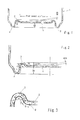
Fig. 1 is a sectional view showing a can bottom shape of a seamless can body according to the present invention. -
Fig. 2 is an enlarged view of an essential portion of the can bottom shape of the seamless can body according to the invention. -
Fig. 3 is an enlarged view of an annular concave portion and a corner portion (panel edge) of the can bottom shape of the seamless can body according to the invention. -
1 Seamless can body 2 Rim portion 3 Annular concave portion 5 Center panel 6 Arc-shaped portion of annular concave portion 7 Straight portion 8 Corner portion 9 Starting point - A seamless can body according to the present invention will be described below in detail based on the drawings.
The seamless canbody 1 according to the invention is a seamless can body formed by a metal plate made of aluminum, tin, tin-free steel, or the like or a seamless can body formed by a covered metal plate formed by covering at least one surface of the metal plate on an inner side of the can body with a resin film made of polyester or the like.
As shown inFig. 1 , the can bottom of the seamless canbody 1 according to the invention is formed by arim portion 2 protruding to an outside of the can, an annularrecessed portion 3 extending continuously from and adjacent to an upper end of an inner wall of therim portion 2 and recessed to the inside of the can, and aflat center panel 5 extending continuously from an inner wall side of the annularconcave portion 3 with a corner portion (center panel edge) 8 interposed therebetween. - As shown in
Figs. 2 and 3 , in a can bottom shape of theseamless can body 1 according to the invention, a shape of a connection between the annularconcave portion 3 and thecenter panel 5 is such that a lower end portion of therim portion 2 is an arc portion having a radius R1 of curvature, that an upper end portion of the annularconcave portion 3 is anarc portion 6 having a radius R2 of curvature, and that the annularconcave portion 3 and the panel edge of thecenter panel 5, i.e., the corner portion 8 having a radius R3 of curvature are connected by a straight portion 7. Astarting point 9 of the arc of the corner portion 8 where the corner portion 8 and the flat face of thecenter panel 5 are connected is an outer peripheral end of thecenter panel 5. - In the seamless can
body 1 according to the invention, by setting the radius R3 of curvature of the corner portion 8 between the annularconcave portion 3 and thecenter panel 5 on the can bottom in a range of 1.5 mm < R3 ≤ 6.0 mm, it is possible to obtain the seamless can body excellent in flatness of the center panel, pressure resistance, and formability as shown in the example described later.
As is clear from the example described later, if the radius R3 of curvature of the corner portion 8 is 1.5 mm or smaller, an excessive tensile load is applied to the corner portion 8 or a portion near the corner portion 8 during forming of the can bottom to cause constriction of thickness (decrease in thickness) at a portion in the circumferential direction of the corner portion and therefore the tensile load applied to the center panel becomes non-uniform in the circumferential direction. As a result, the flatness of the center panel is impaired and increase in a decrease rate of the thickness of the annularconcave portion 3 and a crack or a cut are likely to occur. Such phenomena becomes noticeable especially when the seamless can body is made thin-walled.
On the other hand, if the radius R3 of curvature exceeds 6.0 mm, a diameter of the center panel becomes small and responsivity of a panel swelling amount to can inner pressure becomes small and, as a result, suitability for an internal pressure test and the pressure resistance are likely to decrease. Therefore, by setting the radius R3 of curvature of the corner portion 8 in the range of 1.5 mm < R3 ≤ 6.0 mm and preferably in a range of 2.0 mm < R3 ≤ 4.0 mm, it is possible to obtain the seamless can body having increased flatness of the center panel and excellent in the suitability for the internal pressure test and the formability. - Moreover, a distance (bottom sink) (BS) from a ground contact surface of the
rim portion 2 of the can body to thecenter panel 5 is preferably in a range of 1.0 mm to 5.0 mm. If the bottom sink (BS) is under than 1.0 mm, thecenter panel 5 may protrude further downward than therim portion 2 to impair a self-standing property when inner pressure increases. On the other hand, the distance exceeding 5.0 mm is not preferable because it causes decrease of an inner capacity of the can body and increase of an amount of metal materials to be used as can materials. - Moreover, a distance (bottom counter sink) (CS) from the ground contact surface of the
rim portion 2 to thearc portion 6 having the radius R2 of curvature of the annularconcave portion 3 is preferably in a range of 1.0 mm to 8.0 mm. If the (CS) is shorter than 1.0 mm, the pressure resistance decreases. On the other hand, the (CS) exceeding 8.0 mm is not preferable, because the forming becomes difficult and a forming defect such as a crack occurs.
The radius R2 of curvature of the annularconcave portion 3 is preferably in a range of 0.5 mm to 2.0 mm. The (R2) smaller than 0.5 mm is not preferable, because the forming becomes difficult and the forming defect such as the crack occurs. On the other hand, the (R2) exceeding 2.0 mm is not preferable, because the pressure resistance decreases. - Because the annular
concave portion 3 performs an important function of increasing the pressure resistance of the can bottom of the seamless canbody 1 in the seamless canbody 1 according to the invention, a depth (CS-BS) of the annularconcave portion 3 is preferably equal to or greater than 1.5 mm and smaller than 3.0 mm in terms of the pressure resistance and the formability especially in a case in which the invention is applied to the above-described slightly-positive-pressure can formed by filling and sealing the can after replacing the head space with the inert gas such as nitrogen. This range is preferable, because the pressure resistance in the retort sterilization or the like decreases when the depth is smaller than 1.5 mm and the forming defect such as the crack of the annularconcave portion 3 occurs in forming when the depth is 3.0 mm or greater.
The radius R1 of curvature of the arc portion of therim portion 2 contributes to increase of stability of contact with the ground and contributes, together with the annularconcave portion 3, to increase of the pressure resistance. The radius R1 is preferably in a range of 0.5 mm to 2.0 mm, because the forming becomes difficult and processing pressure in the forming increases to cause the crack or the cut when the radius R1 is smaller than 0.5 mm and the pressure resistance decreases when the radius R1 exceeds 2.0 mm. - The seamless can body according to the invention is applied to the seamless can body having the can bottom of the above-described thickness and formed by using a metal plate of a thickness of 0.2 mm to 0.4 mm when the metal plate is an aluminum plate and by using a metal plate of a thickness of 0.1 mm to 0.3 mm when the metal plate is a steel plate made of tin or tin-free steel.
Especially, the seamless can body according to the invention is applied to the seamless can body having a can body diameter of 53 mm to 66 mm (commonly referred to as a 202 diameter to 211 diameter can body). - The seamless can body according to the invention is intended to improve the suitability for the internal pressure test of the negative-pressure can or the slightly-positive-pressure can filled with low-acid beverage or the like and sealed and is especially suitable for the purpose of preventing damage to the resin film on the above-described corner portion or near the corner portion and deterioration of the content in flavor or occurrence of corrosion caused by exposure of the metal face in the seamless can body formed by drawing/ironing or wall-thinning drawing (stretch drawing)/ironing the covered plate obtained by covering at least one surface of metal material which is on an inner surface of the can body with resin such as polyester resin.
- A distance (mm) of the center portion of the center panel bulging outward or inward from a basis surface (0) which was the outer peripheral edge of the center panel of the can bottom was measured and defined as the flatness (BSD). The flatness was evaluated as follows.
- ○: -0.15 ≤ BSD ≤ 0.15
- X: BSD < -0.15 or BSD > 0.15
- In the present example, the pressure resistance was evaluated by using 490 kPa as a standard value in order to pass 470 kPa which was the standard of the pressure resistance against buckling of the can bottom in the retort sterilization based on the premise that the seamless can body would be used as the slightly-positive-pressure can.
- The formability was evaluated by visually checking a decrease rate of the thickness of the straight portion 7 (between the
center panel 5 and the annular concave portion 3) provided between the corner portion 8 of the center panel and the arc-shapedportion 6 of the annularconcave portion 3 on the can bottom and presence or absence of a forming defect such as a cut (bottom crack) in the can bottom. - ○: No bottom crack, the decrease rate of the thickness was less than 10%
- Δ: No bottom crack, the decrease rate of the thickness was 10% or greater
- ×: Occurrence of the bottom crack
- A circular blank having a diameter of 128 mm was formed by using a laminated plate formed by covering both sides surface of an aluminum metal plate having a thickness of 0.25 mm with a polyester film having a thickness of 16 µm and the circular blank was drawn by using a cupping press into a cup having a body diameter of 73 mm and a height of 40 mm. Then, after redrawing/ironing the cup at a forming speed of 250 spm, an end portion of the cup was trimmed to obtain a seamless can body having a can body thickness (Tw) of 0.105 mm, a thickness of a can body end portion (Tf) of 0.175 mm, a can bottom thickness (TB) of 0.28 mm, and a can body height (BoH) of 143 mm.
- The seamless can bodies having radiuses R3 of curvature of corner portions of the can bottoms of 1.5 mm, 2.0 mm, 4.0 mm, 6.0 mm, and 7.0 mm and depths (CS-BS) of annular concave portions of 1.0 mm, 1.5 mm, 2.1 mm, 2.8 mm, and 3.0 mm were manufactured respectively.
The seamless can bodies having the radiuses R3 of curvature of the corner portions of the can bottoms of 2.0 mm to 6.0 mm which were in the range of 1.5 mm < R3 ≤ 6.0 mm and the depths (CS-BS) of the annular recessed portions of 1.5 mm, 2.1 mm, and 2.8 mm which were in the range of 1.5 mm ≤ (CS-BS) < 3.0 mm were evaluated as respective examples and the seamless can bodies having the radiuses R3 of curvature and the depths (CS-BS) of the annular recessed portions which were out of the ranges were evaluated as respective comparative examples.
Evaluation results of the examples are shown in Table 1 and evaluation results of the comparative examples are shown in Table 2.
In Table 2, "Not Evaluated" means that the flatness, the pressure resistance, and the thickness decrease rates for the formability were not evaluated because a crack was produced in the can bottom of the obtained seamless can body and the seamless can body was not even in a shape of the seamless can body. -


- As a result, it was found that the flatness of the can bottom, the pressure resistance, and the formability can be increased by satisfying the conditions that the radius R3 of curvature of the corner portion connected to the annular concave portion protruding to the inside of the can on the can bottom of the seamless can body is in the range of 1.5 mm < R3 ≤ 6.0 mm and that the depth of the annular concave portion is equal to or greater than 1.5 mm and smaller than 3.0 mm.
- The seamless can body according to the invention can adapt to the internal pressure test for the negative-pressure can and the slightly-positive-pressure can and especially for the slightly-positive-pressure can by maintaining high flatness of the center panel of the can bottom, has the increased pressure resistance and formability, and therefore has wide industrial applicability.
Claims (5)
- A seamless can body having a can bottom shape comprising:a rim portion protruding to an outside of the can;an annular concave portion adjacent to an inner side of the rim portion and protruding to an inside of the can; anda center panel extending continuously from an inner peripheral side of the annular concave portion with a corner portion interposed therebetween, and being flat,wherein a radius R3 of curvature of the corner portion is in a range of 1.5 mm < R3 ≤ 6.0 mm, a depth of the annular concave portion is equal to or greater than 1.5 mm and smaller than 3.0 mm, and flatness (BSD) of the center panel is -0.15 to 0.15 mm.
- The seamless can body according to claim 1, wherein the seamless can body is formed by an aluminum plate and a thickness of the can bottom is 0.2 mm to 0.4 mm.
- The seamless can body according to claim 1, wherein the seamless can body is formed by a steel plate and a thickness of the can bottom is 0.1 mm to 0.3 mm.
- The seamless can body according to any of claims 1 to 3, wherein the seamless can body is for a lightly-positive-pressure can.
- The seamless can body according to any of claims 1 to 3, wherein the seamless can body is a seamless can body with at least an inner surface covered with resin.
Applications Claiming Priority (2)
| Application Number | Priority Date | Filing Date | Title |
|---|---|---|---|
| JP2010131138A JP4877538B2 (en) | 2010-06-08 | 2010-06-08 | Seamless can body |
| PCT/JP2011/061934 WO2011155329A1 (en) | 2010-06-08 | 2011-05-25 | Seamless can body |
Publications (3)
| Publication Number | Publication Date |
|---|---|
| EP2581316A1 true EP2581316A1 (en) | 2013-04-17 |
| EP2581316A4 EP2581316A4 (en) | 2014-05-21 |
| EP2581316B1 EP2581316B1 (en) | 2015-03-04 |
Family
ID=45097937
Family Applications (1)
| Application Number | Title | Priority Date | Filing Date |
|---|---|---|---|
| EP11792286.4A Not-in-force EP2581316B1 (en) | 2010-06-08 | 2011-05-25 | Seamless can body |
Country Status (5)
| Country | Link |
|---|---|
| US (1) | US8960472B2 (en) |
| EP (1) | EP2581316B1 (en) |
| JP (1) | JP4877538B2 (en) |
| CN (1) | CN102933466B (en) |
| WO (1) | WO2011155329A1 (en) |
Families Citing this family (8)
| Publication number | Priority date | Publication date | Assignee | Title |
|---|---|---|---|---|
| US8127588B1 (en) | 2011-03-23 | 2012-03-06 | Halpin Harold W | Apparatus and methods for forming a finger-engaging portion in a stay-on-tab of a lid of a container |
| US10065232B2 (en) | 2013-03-15 | 2018-09-04 | Station 4 Llc | Devices and methods for bending a tab on a container |
| US20140322397A1 (en) * | 2013-04-27 | 2014-10-30 | David F. Mamo | Aseptic hot-brewed packaged coffee or espresso beverage |
| JP7238254B2 (en) * | 2017-10-30 | 2023-03-14 | 東洋製罐株式会社 | can container |
| US10954034B2 (en) * | 2017-11-20 | 2021-03-23 | Gateway Plastics, Inc. | Container with expansion panel |
| JP7378200B2 (en) * | 2017-12-22 | 2023-11-13 | アルテミラ製缶株式会社 | can body |
| JP7456141B2 (en) * | 2019-12-11 | 2024-03-27 | 東洋製罐株式会社 | seamless can body |
| JP7447564B2 (en) * | 2020-03-09 | 2024-03-12 | 東洋製罐グループホールディングス株式会社 | Seamless can body and method for manufacturing seamless can body |
Family Cites Families (14)
| Publication number | Priority date | Publication date | Assignee | Title |
|---|---|---|---|---|
| US3905507A (en) * | 1974-04-05 | 1975-09-16 | Nat Can Corp | Profiled bottom wall for containers |
| JPS5325186A (en) * | 1976-08-20 | 1978-03-08 | Daiwa Can Co Ltd | Metallic can for drink containing carbon dioxide or the like |
| JPS5548037A (en) * | 1978-10-02 | 1980-04-05 | Shinriyou Seikan Kk | Bottom shape of twoopiece tin |
| JPS6024735B2 (en) | 1979-11-28 | 1985-06-14 | 東洋製罐株式会社 | Method and tool for manufacturing draw ironing cans suitable for hammer testing |
| GB2119743B (en) * | 1982-04-19 | 1986-02-12 | American Can Co | Buckle-resistant cans and a method of making them |
| IT1206166B (en) * | 1984-07-26 | 1989-04-14 | Sigma Tau Ind Farmaceuti | DEVICE FOR RELEASING A SUBSTANCE IN A DISSOLUTION FLUID WITH ZERO ORDER KINETICS AND PROCEDURE FOR ITS PREPARATION |
| JPS6143109U (en) * | 1985-05-01 | 1986-03-20 | 大和製缶株式会社 | Beverage DI can body that generates positive internal pressure |
| CA2038817C (en) * | 1990-04-06 | 1997-04-22 | Gary Arthur Baldwin | Beverage container with improved drop resistance |
| GB9216247D0 (en) | 1992-07-30 | 1992-09-09 | Cmb Foodcan Plc | Souffle:can ends |
| JPH11193016A (en) * | 1997-12-26 | 1999-07-21 | Toyo Seikan Kaisha Ltd | Low positive pressure cans with internal pressure inspection suitability and can bodies |
| JP4112689B2 (en) | 1998-06-30 | 2008-07-02 | 大和製罐株式会社 | Seamless can for positive pressure |
| WO2005058520A1 (en) * | 2003-12-17 | 2005-06-30 | Toyo Seikan Kaisha, Ltd. | Method and device for manufacturing synthetic resin coated metal can body |
| EP1813540A1 (en) * | 2006-01-30 | 2007-08-01 | Impress Group B.V. | Can end for a can and such can |
| JP5085411B2 (en) * | 2007-12-26 | 2012-11-28 | 大和製罐株式会社 | Retort compatible small capacity screw can |
-
2010
- 2010-06-08 JP JP2010131138A patent/JP4877538B2/en active Active
-
2011
- 2011-05-25 US US13/702,716 patent/US8960472B2/en active Active
- 2011-05-25 EP EP11792286.4A patent/EP2581316B1/en not_active Not-in-force
- 2011-05-25 CN CN201180027997.4A patent/CN102933466B/en not_active Expired - Fee Related
- 2011-05-25 WO PCT/JP2011/061934 patent/WO2011155329A1/en not_active Ceased
Non-Patent Citations (2)
| Title |
|---|
| No further relevant documents disclosed * |
| See also references of WO2011155329A1 * |
Also Published As
| Publication number | Publication date |
|---|---|
| US8960472B2 (en) | 2015-02-24 |
| CN102933466B (en) | 2014-11-05 |
| JP4877538B2 (en) | 2012-02-15 |
| JP2011255919A (en) | 2011-12-22 |
| EP2581316A4 (en) | 2014-05-21 |
| EP2581316B1 (en) | 2015-03-04 |
| CN102933466A (en) | 2013-02-13 |
| US20130087561A1 (en) | 2013-04-11 |
| WO2011155329A1 (en) | 2011-12-15 |
Similar Documents
| Publication | Publication Date | Title |
|---|---|---|
| US8960472B2 (en) | Seamless can body | |
| AU2011212418B2 (en) | Can body | |
| EP2744013B1 (en) | Cover body for battery case | |
| US20020134788A1 (en) | Metallic beverage can end | |
| US20070274807A1 (en) | Bottom profile for drawn and ironed can body | |
| CN108883852B (en) | Threaded metal container | |
| CN115135581B (en) | Tank container and method of manufacturing the same | |
| EP3350354B1 (en) | Aluminum microstructure for highly shaped products and associated methods | |
| CN118768448A (en) | Seamless tank body and method for manufacturing seamless tank body | |
| EP2640534A1 (en) | Metallic beverage can end closure with offset countersink | |
| EP3328568B1 (en) | Optimized drawing and wall ironing process of aluminum containers | |
| CN114616185B (en) | Tank Container | |
| JP5085411B2 (en) | Retort compatible small capacity screw can | |
| JP7818890B2 (en) | can body | |
| EP3279100A1 (en) | Can body | |
| EP3476964B1 (en) | Steel sheet for crown caps, production method therefor, and crown cap | |
| JP4666327B2 (en) | Can lid | |
| US20220242605A1 (en) | Lightweight beverage can made from aluminum alloy | |
| CN1436144A (en) | Metal can being pressure tight metal packaging | |
| JP5271332B2 (en) | Double winding structure of can | |
| JP6998142B2 (en) | 3-piece can with bead | |
| KR100815770B1 (en) | How to make steel two-piece D & E cans with improved stripping | |
| KR100646261B1 (en) | Metal cans and preparation method thereof | |
| US20180051362A1 (en) | Steel sheet for crown cap, method for manufacturing steel sheet for crown cap, and crown cap | |
| JP2014200811A (en) | Can body machining method and can body |
Legal Events
| Date | Code | Title | Description |
|---|---|---|---|
| PUAI | Public reference made under article 153(3) epc to a published international application that has entered the european phase |
Free format text: ORIGINAL CODE: 0009012 |
|
| 17P | Request for examination filed |
Effective date: 20121219 |
|
| AK | Designated contracting states |
Kind code of ref document: A1 Designated state(s): AL AT BE BG CH CY CZ DE DK EE ES FI FR GB GR HR HU IE IS IT LI LT LU LV MC MK MT NL NO PL PT RO RS SE SI SK SM TR |
|
| DAX | Request for extension of the european patent (deleted) | ||
| A4 | Supplementary search report drawn up and despatched |
Effective date: 20140425 |
|
| RIC1 | Information provided on ipc code assigned before grant |
Ipc: B65D 1/16 20060101AFI20140417BHEP |
|
| GRAP | Despatch of communication of intention to grant a patent |
Free format text: ORIGINAL CODE: EPIDOSNIGR1 |
|
| INTG | Intention to grant announced |
Effective date: 20140923 |
|
| GRAS | Grant fee paid |
Free format text: ORIGINAL CODE: EPIDOSNIGR3 |
|
| GRAA | (expected) grant |
Free format text: ORIGINAL CODE: 0009210 |
|
| AK | Designated contracting states |
Kind code of ref document: B1 Designated state(s): AL AT BE BG CH CY CZ DE DK EE ES FI FR GB GR HR HU IE IS IT LI LT LU LV MC MK MT NL NO PL PT RO RS SE SI SK SM TR |
|
| REG | Reference to a national code |
Ref country code: GB Ref legal event code: FG4D |
|
| REG | Reference to a national code |
Ref country code: CH Ref legal event code: EP |
|
| REG | Reference to a national code |
Ref country code: IE Ref legal event code: FG4D |
|
| REG | Reference to a national code |
Ref country code: DE Ref legal event code: R096 Ref document number: 602011014440 Country of ref document: DE Effective date: 20150409 |
|
| REG | Reference to a national code |
Ref country code: AT Ref legal event code: REF Ref document number: 713627 Country of ref document: AT Kind code of ref document: T Effective date: 20150415 |
|
| REG | Reference to a national code |
Ref country code: FR Ref legal event code: PLFP Year of fee payment: 5 |
|
| REG | Reference to a national code |
Ref country code: AT Ref legal event code: MK05 Ref document number: 713627 Country of ref document: AT Kind code of ref document: T Effective date: 20150304 Ref country code: NL Ref legal event code: VDEP Effective date: 20150304 |
|
| PG25 | Lapsed in a contracting state [announced via postgrant information from national office to epo] |
Ref country code: LT Free format text: LAPSE BECAUSE OF FAILURE TO SUBMIT A TRANSLATION OF THE DESCRIPTION OR TO PAY THE FEE WITHIN THE PRESCRIBED TIME-LIMIT Effective date: 20150304 Ref country code: SE Free format text: LAPSE BECAUSE OF FAILURE TO SUBMIT A TRANSLATION OF THE DESCRIPTION OR TO PAY THE FEE WITHIN THE PRESCRIBED TIME-LIMIT Effective date: 20150304 Ref country code: ES Free format text: LAPSE BECAUSE OF FAILURE TO SUBMIT A TRANSLATION OF THE DESCRIPTION OR TO PAY THE FEE WITHIN THE PRESCRIBED TIME-LIMIT Effective date: 20150304 Ref country code: NO Free format text: LAPSE BECAUSE OF FAILURE TO SUBMIT A TRANSLATION OF THE DESCRIPTION OR TO PAY THE FEE WITHIN THE PRESCRIBED TIME-LIMIT Effective date: 20150604 Ref country code: FI Free format text: LAPSE BECAUSE OF FAILURE TO SUBMIT A TRANSLATION OF THE DESCRIPTION OR TO PAY THE FEE WITHIN THE PRESCRIBED TIME-LIMIT Effective date: 20150304 Ref country code: HR Free format text: LAPSE BECAUSE OF FAILURE TO SUBMIT A TRANSLATION OF THE DESCRIPTION OR TO PAY THE FEE WITHIN THE PRESCRIBED TIME-LIMIT Effective date: 20150304 |
|
| REG | Reference to a national code |
Ref country code: LT Ref legal event code: MG4D |
|
| PG25 | Lapsed in a contracting state [announced via postgrant information from national office to epo] |
Ref country code: RS Free format text: LAPSE BECAUSE OF FAILURE TO SUBMIT A TRANSLATION OF THE DESCRIPTION OR TO PAY THE FEE WITHIN THE PRESCRIBED TIME-LIMIT Effective date: 20150304 Ref country code: GR Free format text: LAPSE BECAUSE OF FAILURE TO SUBMIT A TRANSLATION OF THE DESCRIPTION OR TO PAY THE FEE WITHIN THE PRESCRIBED TIME-LIMIT Effective date: 20150605 Ref country code: LV Free format text: LAPSE BECAUSE OF FAILURE TO SUBMIT A TRANSLATION OF THE DESCRIPTION OR TO PAY THE FEE WITHIN THE PRESCRIBED TIME-LIMIT Effective date: 20150304 Ref country code: AT Free format text: LAPSE BECAUSE OF FAILURE TO SUBMIT A TRANSLATION OF THE DESCRIPTION OR TO PAY THE FEE WITHIN THE PRESCRIBED TIME-LIMIT Effective date: 20150304 |
|
| PG25 | Lapsed in a contracting state [announced via postgrant information from national office to epo] |
Ref country code: NL Free format text: LAPSE BECAUSE OF FAILURE TO SUBMIT A TRANSLATION OF THE DESCRIPTION OR TO PAY THE FEE WITHIN THE PRESCRIBED TIME-LIMIT Effective date: 20150304 |
|
| PG25 | Lapsed in a contracting state [announced via postgrant information from national office to epo] |
Ref country code: EE Free format text: LAPSE BECAUSE OF FAILURE TO SUBMIT A TRANSLATION OF THE DESCRIPTION OR TO PAY THE FEE WITHIN THE PRESCRIBED TIME-LIMIT Effective date: 20150304 Ref country code: PT Free format text: LAPSE BECAUSE OF FAILURE TO SUBMIT A TRANSLATION OF THE DESCRIPTION OR TO PAY THE FEE WITHIN THE PRESCRIBED TIME-LIMIT Effective date: 20150706 Ref country code: SK Free format text: LAPSE BECAUSE OF FAILURE TO SUBMIT A TRANSLATION OF THE DESCRIPTION OR TO PAY THE FEE WITHIN THE PRESCRIBED TIME-LIMIT Effective date: 20150304 Ref country code: CZ Free format text: LAPSE BECAUSE OF FAILURE TO SUBMIT A TRANSLATION OF THE DESCRIPTION OR TO PAY THE FEE WITHIN THE PRESCRIBED TIME-LIMIT Effective date: 20150304 Ref country code: RO Free format text: LAPSE BECAUSE OF FAILURE TO SUBMIT A TRANSLATION OF THE DESCRIPTION OR TO PAY THE FEE WITHIN THE PRESCRIBED TIME-LIMIT Effective date: 20150304 |
|
| PG25 | Lapsed in a contracting state [announced via postgrant information from national office to epo] |
Ref country code: IS Free format text: LAPSE BECAUSE OF FAILURE TO SUBMIT A TRANSLATION OF THE DESCRIPTION OR TO PAY THE FEE WITHIN THE PRESCRIBED TIME-LIMIT Effective date: 20150704 Ref country code: PL Free format text: LAPSE BECAUSE OF FAILURE TO SUBMIT A TRANSLATION OF THE DESCRIPTION OR TO PAY THE FEE WITHIN THE PRESCRIBED TIME-LIMIT Effective date: 20150304 |
|
| REG | Reference to a national code |
Ref country code: DE Ref legal event code: R097 Ref document number: 602011014440 Country of ref document: DE |
|
| PG25 | Lapsed in a contracting state [announced via postgrant information from national office to epo] |
Ref country code: IT Free format text: LAPSE BECAUSE OF FAILURE TO SUBMIT A TRANSLATION OF THE DESCRIPTION OR TO PAY THE FEE WITHIN THE PRESCRIBED TIME-LIMIT Effective date: 20150304 |
|
| REG | Reference to a national code |
Ref country code: CH Ref legal event code: PL |
|
| PLBE | No opposition filed within time limit |
Free format text: ORIGINAL CODE: 0009261 |
|
| STAA | Information on the status of an ep patent application or granted ep patent |
Free format text: STATUS: NO OPPOSITION FILED WITHIN TIME LIMIT |
|
| PG25 | Lapsed in a contracting state [announced via postgrant information from national office to epo] |
Ref country code: LU Free format text: LAPSE BECAUSE OF FAILURE TO SUBMIT A TRANSLATION OF THE DESCRIPTION OR TO PAY THE FEE WITHIN THE PRESCRIBED TIME-LIMIT Effective date: 20150525 Ref country code: DK Free format text: LAPSE BECAUSE OF FAILURE TO SUBMIT A TRANSLATION OF THE DESCRIPTION OR TO PAY THE FEE WITHIN THE PRESCRIBED TIME-LIMIT Effective date: 20150304 Ref country code: CH Free format text: LAPSE BECAUSE OF NON-PAYMENT OF DUE FEES Effective date: 20150531 Ref country code: MC Free format text: LAPSE BECAUSE OF FAILURE TO SUBMIT A TRANSLATION OF THE DESCRIPTION OR TO PAY THE FEE WITHIN THE PRESCRIBED TIME-LIMIT Effective date: 20150304 Ref country code: LI Free format text: LAPSE BECAUSE OF NON-PAYMENT OF DUE FEES Effective date: 20150531 |
|
| 26N | No opposition filed |
Effective date: 20151207 |
|
| REG | Reference to a national code |
Ref country code: IE Ref legal event code: MM4A |
|
| PG25 | Lapsed in a contracting state [announced via postgrant information from national office to epo] |
Ref country code: SI Free format text: LAPSE BECAUSE OF FAILURE TO SUBMIT A TRANSLATION OF THE DESCRIPTION OR TO PAY THE FEE WITHIN THE PRESCRIBED TIME-LIMIT Effective date: 20150304 |
|
| PG25 | Lapsed in a contracting state [announced via postgrant information from national office to epo] |
Ref country code: IE Free format text: LAPSE BECAUSE OF NON-PAYMENT OF DUE FEES Effective date: 20150525 |
|
| REG | Reference to a national code |
Ref country code: FR Ref legal event code: PLFP Year of fee payment: 6 |
|
| PG25 | Lapsed in a contracting state [announced via postgrant information from national office to epo] |
Ref country code: BE Free format text: LAPSE BECAUSE OF FAILURE TO SUBMIT A TRANSLATION OF THE DESCRIPTION OR TO PAY THE FEE WITHIN THE PRESCRIBED TIME-LIMIT Effective date: 20150304 |
|
| PG25 | Lapsed in a contracting state [announced via postgrant information from national office to epo] |
Ref country code: MT Free format text: LAPSE BECAUSE OF FAILURE TO SUBMIT A TRANSLATION OF THE DESCRIPTION OR TO PAY THE FEE WITHIN THE PRESCRIBED TIME-LIMIT Effective date: 20150304 |
|
| REG | Reference to a national code |
Ref country code: FR Ref legal event code: PLFP Year of fee payment: 7 |
|
| PG25 | Lapsed in a contracting state [announced via postgrant information from national office to epo] |
Ref country code: SM Free format text: LAPSE BECAUSE OF FAILURE TO SUBMIT A TRANSLATION OF THE DESCRIPTION OR TO PAY THE FEE WITHIN THE PRESCRIBED TIME-LIMIT Effective date: 20150304 Ref country code: BG Free format text: LAPSE BECAUSE OF FAILURE TO SUBMIT A TRANSLATION OF THE DESCRIPTION OR TO PAY THE FEE WITHIN THE PRESCRIBED TIME-LIMIT Effective date: 20150304 Ref country code: HU Free format text: LAPSE BECAUSE OF FAILURE TO SUBMIT A TRANSLATION OF THE DESCRIPTION OR TO PAY THE FEE WITHIN THE PRESCRIBED TIME-LIMIT; INVALID AB INITIO Effective date: 20110525 |
|
| PG25 | Lapsed in a contracting state [announced via postgrant information from national office to epo] |
Ref country code: CY Free format text: LAPSE BECAUSE OF FAILURE TO SUBMIT A TRANSLATION OF THE DESCRIPTION OR TO PAY THE FEE WITHIN THE PRESCRIBED TIME-LIMIT Effective date: 20150304 |
|
| PG25 | Lapsed in a contracting state [announced via postgrant information from national office to epo] |
Ref country code: TR Free format text: LAPSE BECAUSE OF FAILURE TO SUBMIT A TRANSLATION OF THE DESCRIPTION OR TO PAY THE FEE WITHIN THE PRESCRIBED TIME-LIMIT Effective date: 20150304 |
|
| REG | Reference to a national code |
Ref country code: FR Ref legal event code: PLFP Year of fee payment: 8 |
|
| PG25 | Lapsed in a contracting state [announced via postgrant information from national office to epo] |
Ref country code: MK Free format text: LAPSE BECAUSE OF FAILURE TO SUBMIT A TRANSLATION OF THE DESCRIPTION OR TO PAY THE FEE WITHIN THE PRESCRIBED TIME-LIMIT Effective date: 20150304 |
|
| PG25 | Lapsed in a contracting state [announced via postgrant information from national office to epo] |
Ref country code: AL Free format text: LAPSE BECAUSE OF FAILURE TO SUBMIT A TRANSLATION OF THE DESCRIPTION OR TO PAY THE FEE WITHIN THE PRESCRIBED TIME-LIMIT Effective date: 20150304 |
|
| PGFP | Annual fee paid to national office [announced via postgrant information from national office to epo] |
Ref country code: GB Payment date: 20240521 Year of fee payment: 14 |
|
| PGFP | Annual fee paid to national office [announced via postgrant information from national office to epo] |
Ref country code: DE Payment date: 20240521 Year of fee payment: 14 |
|
| PGFP | Annual fee paid to national office [announced via postgrant information from national office to epo] |
Ref country code: FR Payment date: 20240528 Year of fee payment: 14 |
|
| REG | Reference to a national code |
Ref country code: DE Ref legal event code: R119 Ref document number: 602011014440 Country of ref document: DE |
|
| GBPC | Gb: european patent ceased through non-payment of renewal fee |
Effective date: 20250525 |
|
| PG25 | Lapsed in a contracting state [announced via postgrant information from national office to epo] |
Ref country code: GB Free format text: LAPSE BECAUSE OF NON-PAYMENT OF DUE FEES Effective date: 20250525 |
|
| PG25 | Lapsed in a contracting state [announced via postgrant information from national office to epo] |
Ref country code: DE Free format text: LAPSE BECAUSE OF NON-PAYMENT OF DUE FEES Effective date: 20251202 |
|
| PG25 | Lapsed in a contracting state [announced via postgrant information from national office to epo] |
Ref country code: FR Free format text: LAPSE BECAUSE OF NON-PAYMENT OF DUE FEES Effective date: 20250531 |