EP2581298A1 - Folding bicycle, particularly a pedal-assist bicycle - Google Patents
Folding bicycle, particularly a pedal-assist bicycle Download PDFInfo
- Publication number
- EP2581298A1 EP2581298A1 EP11382318.1A EP11382318A EP2581298A1 EP 2581298 A1 EP2581298 A1 EP 2581298A1 EP 11382318 A EP11382318 A EP 11382318A EP 2581298 A1 EP2581298 A1 EP 2581298A1
- Authority
- EP
- European Patent Office
- Prior art keywords
- bicycle
- connecting part
- down tube
- transverse shaft
- folding
- Prior art date
- Legal status (The legal status is an assumption and is not a legal conclusion. Google has not performed a legal analysis and makes no representation as to the accuracy of the status listed.)
- Withdrawn
Links
Images


Classifications
-
- B—PERFORMING OPERATIONS; TRANSPORTING
- B62—LAND VEHICLES FOR TRAVELLING OTHERWISE THAN ON RAILS
- B62K—CYCLES; CYCLE FRAMES; CYCLE STEERING DEVICES; RIDER-OPERATED TERMINAL CONTROLS SPECIALLY ADAPTED FOR CYCLES; CYCLE AXLE SUSPENSIONS; CYCLE SIDE-CARS, FORECARS, OR THE LIKE
- B62K3/00—Bicycles
- B62K3/02—Frames
- B62K3/10—Frames of single-beam type, i.e. connecting steering head to rear axle
-
- B—PERFORMING OPERATIONS; TRANSPORTING
- B62—LAND VEHICLES FOR TRAVELLING OTHERWISE THAN ON RAILS
- B62K—CYCLES; CYCLE FRAMES; CYCLE STEERING DEVICES; RIDER-OPERATED TERMINAL CONTROLS SPECIALLY ADAPTED FOR CYCLES; CYCLE AXLE SUSPENSIONS; CYCLE SIDE-CARS, FORECARS, OR THE LIKE
- B62K15/00—Collapsible or foldable cycles
- B62K15/006—Collapsible or foldable cycles the frame being foldable
Definitions
- the present invention is comprised in the technical field of folding bicycles and, particularly in the technical field of pedal-assist folding bicycles, assisted by an electric motor.
- Folding bicycles have been known for many years. These bicycles conventionally comprise a hinge system located in the down tube of the frame which allows laterally folding the back portion of the bicycle over the front portion.
- the battery is located precisely in the down tube of the frame, such as for example in the frame described in Utility Model ES- ES1072110-U , so it is impossible to provide the down tube with an articulation or hinge.
- folding systems have been conceived such as the one described for example in patent application WO03022671A1 , which allows laterally folding the back portion of the bicycle over its front portion based on an articulation provided in the attachment of the down tube with the seat tube.
- the location of this articulation is at a point where many loads coincide when the bicycle is in use, so this system is complicated and susceptible to breaks.
- the object of the present invention is to overcome the drawbacks of the state of the art described above by means of a folding bicycle, particularly a pedal-assist bicycle, comprising a frame with a down tube with a back end with a seat tube and a front end with a steering tube susceptible to housing a stem connected in the upper zone to a handlebar and in the lower zone to a front fork, a back fork coupled to the back end of the down tube and a bottom bracket, a folding mechanism which allows folding the bicycle about an articulating pin to at least one folded position, and a locking mechanism for keeping the bicycle in said folded position, the folding bicycle being characterized in that the bottom bracket is integrated in a lower portion of a connecting part emerging in the lower zone of a front portion of the back fork; the connecting part comprises an upper side with a back portion attached in the lower zone to the front portion of the back fork and with at least one cantilevered axial extension which extends below and is connected to the down tube in the unfolded position of the bicycle; the axial
- the connecting part can be a triangular part the upper side of which comprises said axial extension, and comprising a front upper vertex in which said front end articulated to the down tube is located and a lower vertex in which the bottom bracket is integrated.
- the connecting part further comprises a housing which is axially aligned with the seat tube in the unfolded position of the bicycle for housing the lower portion of a seat post lockable in the seat tube by fixing means such as, for example, a quick-tightening clamp, such that the lower portion of the seat post prevents the folding of the bicycle.
- the front portion of the back fork can comprise a front face in which an inner seal made of an elastically flexible material is arranged, which, is trapped between the back end of the down tube and the front face of the front portion of the back fork in the unfolded position of the bicycle.
- the back end of the down tube can comprise a back portion projecting from the seat tube.
- the upper side of the connecting part comprises the axial extension comprising a pair of front ends or alternatively two axial extensions spaced from one another with respective front ends.
- the front ends are spaced from one another and provided with respective cylindrical holes transversely aligned with one another and with respect to a cylindrical passage of a lug emerging in the lower zone of the down tube, such that the transverse shaft is housed in said cylindrical passage and in said cylindrical holes, an articulation thus being formed for the pivoting block.
- the cylindrical holes in the axial extensions can have respective pairs of opposite inner ribs fitting in a pair of complementary outer longitudinal grooves in the periphery of the transverse shaft, such that the transverse shaft rotates integrally with the axial extensions of the upper side of the connecting part.
- a locking mechanism in which the transverse shaft comprises a cylindrical inner axial passage extending internally through at least a portion of the length of the transverse shaft and having an open end and a closed portion, opposite the open end.
- An also cylindrical guide element diagonally traversed by a perpendicular pin is slidingly housed in the end portion adjacent to the open end of the axial passage, which perpendicular pin also traverses respective slits located in diagonally opposite positions of the wall of the transverse shaft, and is immobilized by its opposite ends in diagonally opposite openings provided in the wall of one of the cylindrical holes of the front end of one of the axial extensions of the upper portion of the triangular connecting part.
- Each of the slits has a proximal smaller edge adjacent to the open end of the axial passage and a distal smaller edge spaced from the adjacent end of the open end of the axial passage as well as two opposite larger edges extending between said smaller edges.
- a compressed coil spring is arranged between the closed portion of the axial passage and the end of the guide element inserted in the axial passage such that it pushes the guide element towards the open end of the axial passage and keeps the perpendicular pin supported against the proximal smaller edges of the respective slits.
- the coil spring preferably forces the distal end portion of the transverse shaft opposite the open end of the axial passage to emerge laterally from the cylindrical hole of the front end of one of the axial extensions of the upper portion of the triangular connecting part.
- Two axially aligned bosses emerging towards the inside of the cylindrical passage can be provided in the lower zone of the lug and they have a height such that they are susceptible to being axially guided in any of the outer longitudinal grooves of the transverse shaft.
- These outer longitudinal grooves are communicated by two outer radial grooves which are sized for guiding the bosses from one outer longitudinal groove to another, and away from and towards the side recesses, and they can be provided with respective side recesses extending towards the slits of the transverse shaft and are sized for retaining the respective bosses in an intermediate locking position.
- the distal end portion of the transverse shaft is pressed again against the force of the coil spring until the perpendicular pin again hits against the respective distal smaller edges of the slits and the bosses of the lug are again facing and can enter the respective outer radial grooves when the pivoting block connected to the horizontal shaft is further rotated until the bosses enter the other outer longitudinal groove of the transverse shaft such that the horizontal shaft cannot continue rotating such that if the distal end portion of the horizontal shaft is no longer pressed before or after the bosses guided in the outer side grooves have reached that other outer longitudinal groove, the bosses again become misaligned with respect to the outer radial grooves due to the action of the coil spring and the locking mechanism takes a maximum locking position.
- the present invention solves the drawbacks of the state of the art in a simple and effective manner.
- the pedal-assist folding bicycle -1- comprises a frame comprising a down tube -4- in which the battery -5- and the control means of the battery -5'- are assembled as described in Utility Model ES- ES1072110-U .
- the down tube -4- extends between the seat tube -6- in which the seat post -3- is housed and the steering tube -10- in which the telescopic stem -9- connected to the handlebar -101- and to the front fork -11- of the front wheel -112- rotates.
- the back wheel -227- of the bicycle -1- has a hub which, in a known manner, incorporates an electric motor (not shown in the drawings) for assisting the propulsion of the bicycle -1-, and it is assembled between two chainstays -225- of a back fork -22- integral with a triangular connecting part -23-.
- the triangular connecting part -23- comprises an upper side -232- the back portion of which emerges in the lower zone of a front portion -226- of the back fork -22-.
- the front portion of the upper side -232- of the triangular connecting part - 23- is formed by two cantilevered axial extensions -233-, the front ends -221- of which (see Figure 4 ), corresponding to front upper vertices of the triangular connecting part -23-, are articulated in a transverse shaft -12-.
- the bottom bracket -236- is integrated in the lower zone -234- of the triangular connecting part -23- in a position corresponding to its lower vertex.
- the back fork -22- and the triangular connecting part -23- thus form a pivoting block -2- susceptible to pivoting with respect to the down tube -4- in a vertical plane between an unfolded position, in which the front portion -226- of the back fork -22- is connected to the seat tube -6-, and a position folded, in which the pivoting block -2- is pivoted towards the steering tube -10-.
- the triangular connecting part -23- further comprises a housing -235- which is axially aligned with the seat tube -6- in the unfolded position of the bicycle -1- such that the lower portion of the seat post -3- enters the housing -235- of the triangular connecting part -23-.
- the quick-tightening clamp -7- is loosened and the seat post -3- is extracted from the housing -235- of the triangular connecting part -23- such that the pivoting block -2- is released and can pivot on the transverse shaft -12- towards the steering tube -10-.
- the back fork -22- remains axially aligned with the down tube -4- in the unfolded position of the bicycle -1-.
- a half-round inner elastomeric seal -8- is provided in the front portion -226- of the back fork -22- preventing metal/metal contact of the front portion -226- of the back fork -22- and the seat tube -6- and, therefore, it prevents noise from being generated due to metal/metal friction and vibrations from being transmitted between the back fork -22- and the seat tube -6-, and a protective outer seal -81- clamping the back end of the down tube -4- is also provided for preventing the entrance of moisture and foreign matter between the back end portion of the down tube -4- and the front portion -226-, and for protecting the inner seal -8- against the effects of moisture and foreign matter.
- an elastomeric plate -13- preventing metal/metal contact of the front side -231- of the triangular connecting part -23- and the down tube -4- when the front side -231- of the triangular connecting part -23- remains connected to the down tube -4- in the completely folded position of the bicycle -1- is arranged in the front side -231- of the triangular connecting part -23-.
- the bicycle -1- can be folded towards an intermediate folded position ( Figure 2 ) and a maximum folded position ( Figure 3 ).
- the pivoting block -2- is folded towards the front wheel -112- such that the chainstays -225- of the back fork -23- are located in a substantially vertical plane, such that the bicycle -1- can roll on its front and back wheels and the front wheel -112- can be steered freely towards the right and left.
- This intermediate folded position is useful when the bicycle is to be introduced in a space having reduced dimensions, for example in an elevator or in a storage room, or transported through a reduced space, such as for example on stairs or in hallways.
- a locking mechanism such as that illustrated in Figure 4 and the following figures and which will be described below can be provided.
- the front ends -221- of the axial extensions -233- of the upper portion of the triangular connecting part -23- are provided with respective cylindrical holes -223-.
- a lug -41- emerging in the lower zone of the down tube -4- provided with a transverse cylindrical passage -42- aligned with the cylindrical holes -223- of the front ends -221- of the axial extensions -233- of the upper portion of the triangular connecting part -23- is arranged between said front ends -221-, such that the transverse shaft -12- traverses the cylindrical passage -42- and the cylindrical holes -223-, which allows the pivoting block -2- to rotate between the previously mentioned folded and unfolded positions of the bicycle -1-.
- Respective washers -17- through which the transverse shaft -12- passes and which reduce friction and aid in the pivoting of the pivoting block -2- are arranged between the sides of the lug -41- and the mentioned front ends -221-.
- the cylindrical holes -223- of the axial extensions -233- have respective pairs of opposite inner ribs -222- fitting in a pair of complementary outer longitudinal grooves -121- provided in the periphery of the transverse shaft -12-, such that the transverse shaft -12- rotates integrally with the axial extensions -233- of the upper side -232- of the triangular connecting part -23- and, therefore, with the pivoting block -2-.
- the transverse shaft -12- comprises an inner cylindrical axial passage -125- extending internally through at least a portion of the length of the transverse shaft -12- and having an open end and a closed portion, opposite the open end.
- An also cylindrical guide element -15- diagonally traversed by a perpendicular pin -14- is slidingly housed in the end portion adjacent to the open end of the axial passage -125-.
- the perpendicular pin -14- also traverses respective slits -122- located in diagonally opposite positions of the wall of the transverse shaft -12-, and is immobilized by its opposite ends in diagonally opposite openings -224- provided in the wall of one of the cylindrical holes -223- of the front end -221- of one of the axial extensions -233- of the upper portion of the triangular connecting part -23-.
- Each of the slits -122- has a proximal smaller edge adjacent to the open end of the axial passage -125- and a distal smaller edge spaced from the adjacent end of the open end of the axial passage -125- as well as two opposite larger edges extending between said smaller edges.
- a compressed coil spring -16- is arranged between the closed portion of the axial passage -125- and the end of the guide element -15- inserted in the axial passage -125-, such that it pushes the guide element -15- towards the open end of the axial passage -125- and, therefore, keeps the perpendicular pin -14- supported against the proximal smaller edges of the respective slits -122-.
- the action of the spring -16- forces the distal end portion -126- of the transverse shaft -12- opposite the open end of the axial passage -125- to emerge laterally from the cylindrical hole -223- of the front end -221- of one of the axial extensions -233- of the upper portion of the triangular connecting part -23-.
- the transverse shaft -12- is coupled to the pivoting block -2-.
- Two axially aligned bosses -18- emerging towards the inside of the cylindrical passage -42- are provided in the lower zone of the lug -41- and they have a height such that they are susceptible to being axially guided in any of the outer longitudinal grooves -121- of the transverse shaft -12-.
- the outer longitudinal grooves -121- are communicated by two outer radial grooves -123- provided with respective side recesses -124- extending towards the slits -122- of the transverse shaft -12-.
- the outer radial grooves -123- are sized for guiding the bosses -18- from one outer longitudinal groove to another, and away from and towards the side recesses -124-.
- the side recesses -124- are sized for retaining the respective bosses -18- in an intermediate locking position.
- the distal end portion -126- of the transverse shaft -12- is pressed again against the force of the coil spring -16- until the perpendicular pin -14- again hits against the respective distal smaller edges of the slits -122- and the bosses -18- of the lug -41- are again facing and can enter the respective outer radial grooves -123- when the pivoting block -2- connected to the horizontal shaft -12- is further rotated until the bosses -18- enter the other outer longitudinal groove -121- of the transverse shaft -12- such that the horizontal shaft -12- cannot continue rotating such that if the distal end portion -126- of the horizontal shaft -12- is no longer pressed before or after the bosses -18- guided in the outer side grooves -123- have reached that other outer longitudinal groove -121-, the bosses -18- again become misaligned with respect to the outer
Abstract
the bottom bracket (236) is integrated in a lower portion (234) of a connecting part (23) emerging in the lower zone of a front portion (226) of the back fork (22);
the connecting part (23) comprises an upper side (232) with a back portion attached in the lower zone to the front portion (226) of the back fork (22) and with at least one cantilevered axial extension (233) which extends below and is connected to the down tube (4) in the unfolded position of the bicycle (1);
the axial extension (233) comprises at least one front end (221) articulated in the lower zone to the down tube (4) by means of a transverse shaft (12)
the front portion (226) of the back fork (22) is connected to the back end of the down tube (4) in the unfolded position of the bicycle (1).
Description
- The present invention is comprised in the technical field of folding bicycles and, particularly in the technical field of pedal-assist folding bicycles, assisted by an electric motor.
- Folding bicycles have been known for many years. These bicycles conventionally comprise a hinge system located in the down tube of the frame which allows laterally folding the back portion of the bicycle over the front portion.
- In different pedal-assist bicycle models, the battery is located precisely in the down tube of the frame, such as for example in the frame described in Utility Model ES-
ES1072110-U WO03022671A1 - The object of the present invention is to overcome the drawbacks of the state of the art described above by means of a folding bicycle, particularly a pedal-assist bicycle, comprising a frame with a down tube with a back end with a seat tube and a front end with a steering tube susceptible to housing a stem connected in the upper zone to a handlebar and in the lower zone to a front fork, a back fork coupled to the back end of the down tube and a bottom bracket, a folding mechanism which allows folding the bicycle about an articulating pin to at least one folded position, and a locking mechanism for keeping the bicycle in said folded position, the folding bicycle being characterized in that
the bottom bracket is integrated in a lower portion of a connecting part emerging in the lower zone of a front portion of the back fork;
the connecting part comprises an upper side with a back portion attached in the lower zone to the front portion of the back fork and with at least one cantilevered axial extension which extends below and is connected to the down tube in the unfolded position of the bicycle;
the axial extension comprises at least one front end articulated in the lower zone to the down tube by means of a transverse shaft, such that the back fork and the connecting part form a pivoting block susceptible to rotating jointly in a vertical plane towards the steering tube to said folded position;
the front portion of the fork is connected to the back end of the down tube in the unfolded position of the bicycle. - According to the invention, the connecting part can be a triangular part the upper side of which comprises said axial extension, and comprising a front upper vertex in which said front end articulated to the down tube is located and a lower vertex in which the bottom bracket is integrated. Preferably, the connecting part further comprises a housing which is axially aligned with the seat tube in the unfolded position of the bicycle for housing the lower portion of a seat post lockable in the seat tube by fixing means such as, for example, a quick-tightening clamp, such that the lower portion of the seat post prevents the folding of the bicycle.
- The front portion of the back fork can comprise a front face in which an inner seal made of an elastically flexible material is arranged, which, is trapped between the back end of the down tube and the front face of the front portion of the back fork in the unfolded position of the bicycle. The back end of the down tube can comprise a back portion projecting from the seat tube.
- In one embodiment of the articulation mechanism, the upper side of the connecting part comprises the axial extension comprising a pair of front ends or alternatively two axial extensions spaced from one another with respective front ends. In both cases, the front ends are spaced from one another and provided with respective cylindrical holes transversely aligned with one another and with respect to a cylindrical passage of a lug emerging in the lower zone of the down tube, such that the transverse shaft is housed in said cylindrical passage and in said cylindrical holes, an articulation thus being formed for the pivoting block. In this embodiment of the articulation mechanism, the cylindrical holes in the axial extensions can have respective pairs of opposite inner ribs fitting in a pair of complementary outer longitudinal grooves in the periphery of the transverse shaft, such that the transverse shaft rotates integrally with the axial extensions of the upper side of the connecting part.
- In this embodiment of the articulation mechanism, a locking mechanism can be provided in which the transverse shaft comprises a cylindrical inner axial passage extending internally through at least a portion of the length of the transverse shaft and having an open end and a closed portion, opposite the open end. An also cylindrical guide element diagonally traversed by a perpendicular pin is slidingly housed in the end portion adjacent to the open end of the axial passage, which perpendicular pin also traverses respective slits located in diagonally opposite positions of the wall of the transverse shaft, and is immobilized by its opposite ends in diagonally opposite openings provided in the wall of one of the cylindrical holes of the front end of one of the axial extensions of the upper portion of the triangular connecting part. Each of the slits has a proximal smaller edge adjacent to the open end of the axial passage and a distal smaller edge spaced from the adjacent end of the open end of the axial passage as well as two opposite larger edges extending between said smaller edges. A compressed coil spring is arranged between the closed portion of the axial passage and the end of the guide element inserted in the axial passage such that it pushes the guide element towards the open end of the axial passage and keeps the perpendicular pin supported against the proximal smaller edges of the respective slits. The coil spring preferably forces the distal end portion of the transverse shaft opposite the open end of the axial passage to emerge laterally from the cylindrical hole of the front end of one of the axial extensions of the upper portion of the triangular connecting part.
- Two axially aligned bosses emerging towards the inside of the cylindrical passage can be provided in the lower zone of the lug and they have a height such that they are susceptible to being axially guided in any of the outer longitudinal grooves of the transverse shaft. These outer longitudinal grooves are communicated by two outer radial grooves which are sized for guiding the bosses from one outer longitudinal groove to another, and away from and towards the side recesses, and they can be provided with respective side recesses extending towards the slits of the transverse shaft and are sized for retaining the respective bosses in an intermediate locking position.
- The operation of the aforementioned locking mechanism is as follows:
- In the use position, i.e., in the unfolded position of the bicycle, the back fork is axially aligned with the down tube and the bosses remain housed in one of the outer longitudinal grooves of the transverse shaft. Once the seat post is extracted from the housing of the triangular connecting part to transition into an intermediate folded position, the pivoting block is folded towards the front wheel such that the chainstays of the back fork are located in a substantially vertical plane, such that the bicycle can roll on its front and back wheels and the front wheel can be steered freely towards the right and left. This intermediate folded position is useful when the bicycle is to be introduced in a space having reduced dimensions, for example in an elevator or in a storage room, or transported through a reduced space, such as for example on stairs or in hallways. In order to be able to perform the folding towards said intermediate folded position, the distal end portion of the transverse shaft is pressed against the force of the coil spring until the perpendicular pin hits against the respective distal smaller edges of the slits and the bosses of the lug are facing and can enter the respective outer radial grooves when the pivoting block connected to the horizontal shaft is rotated. When the distal end portion of the transverse shaft is no longer pressed once the bosses have entered the outer radial grooves and the pivoting block continues to be rotated, the action of the spring makes the bosses enter and remain locked in the side recesses of the outer radial grooves in said intermediate locking position in which the bicycle is folded and locked in the intermediate folded position described above.
- In the maximum folded position, in which the front wheel is disassembled and the pivoting block has been folded forward until the elastomeric plate arranged in the front side of the triangular connecting part hits against the lower portion of the down tube such that the back fork is diagonally folded forward and the back wheel is located below the down tube and partially between the arms of the front fork. For transitioning from the intermediate folded position to this maximum folded position of the bicycle, the distal end portion of the transverse shaft is pressed again against the force of the coil spring until the perpendicular pin again hits against the respective distal smaller edges of the slits and the bosses of the lug are again facing and can enter the respective outer radial grooves when the pivoting block connected to the horizontal shaft is further rotated until the bosses enter the other outer longitudinal groove of the transverse shaft such that the horizontal shaft cannot continue rotating such that if the distal end portion of the horizontal shaft is no longer pressed before or after the bosses guided in the outer side grooves have reached that other outer longitudinal groove, the bosses again become misaligned with respect to the outer radial grooves due to the action of the coil spring and the locking mechanism takes a maximum locking position.
- As can be deduced from the foregoing description, the present invention solves the drawbacks of the state of the art in a simple and effective manner.
- Aspects and embodiments of the invention are described below based on schematic drawings in which
-
Figure 1 is a rear perspective view of an embodiment of a pedal-assist bicycle according to the present invention, in the unfolded position; -
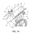
Figure 1A is a detail view of the folding area of the bicycle shown inFigure 1 ; -
Figure 2 shows the bicycle ofFigure 1 in an intermediate folded position; -
Figure 3 shows the bicycle ofFigure 1 in a maximum folded position; -
Figure 4 is an exploded front perspective view of the components of a locking mechanism that can be integrated in the bicycle shown inFigures 1 to 3 ; -
Figure 5 shows in further detail some of the components of the locking mechanism and their respective positions at the start of a folding operation of the bicycle; -
Figure 6 shows in further detail some of the components of the locking mechanism and their respective positions when the bicycle is in the intermediate folded position shown inFigure 2 ; -
Figure 7 shows in further detail some of the components of the locking mechanism and their respective positions when the bicycle is in the maximum folded position shown inFigure 3 . - These drawings show reference numbers identifying the following elements:
- 1
- folding bicycle
- 2
- pivoting block
- 22
- back fork
- 221
- front ends of the axial extensions
- 222
- inner ribs
- 223
- cylindrical holes
- 224
- cylindrical openings
- 225
- chainstays
- 226
- front portion of the back fork
- 227
- back wheel
- 23
- triangular connecting part
- 231
- front side of the triangular connecting part
- 232
- upper side of the triangular connecting part
- 233
- axial extensions of the upper portion of the triangular connecting part
- 234
- lower portion of the triangular connecting part
- 235
- housing for the lower end of the seat post
- 236
- bottom bracket
- 3
- seat post
- 31
- seat
- 4
- down tube
- 41
- lug
- 42
- cylindrical passage
- 5
- battery
- 5'
- control means of the battery
- 6
- seat tu be
- 7
- quick-tightening clamp
- 8
- half-round elastomeric seal
- 81
- protective outer seal
- 9
- telescopic stem
- 91
- conventional folding mechanism
- 10
- steering tube
- 101
- handlebar
- 11
- front fork
- 111
- arms of the front fork
- 112
- front wheel
- 12
- transverse shaft
- 121
- outer longitudinal grooves
- 122
- slits
- 128
- outer radial grooves
- 124
- side recesses
- 125
- axial passage
- 126
- distal end portion of the transverse shaft
- 18
- elastomeric plate
- 14
- perpendicular pin
- 15
- guide element
- 16
- coil spring
- 17
- washers
- 18
- bosses
- In the embodiment of the invention shown in the drawings, the pedal-assist folding bicycle -1- comprises a frame comprising a down tube -4- in which the battery -5- and the control means of the battery -5'- are assembled as described in Utility Model ES-
ES1072110-U - The back wheel -227- of the bicycle -1- has a hub which, in a known manner, incorporates an electric motor (not shown in the drawings) for assisting the propulsion of the bicycle -1-, and it is assembled between two chainstays -225- of a back fork -22- integral with a triangular connecting part -23-. The triangular connecting part -23- comprises an upper side -232- the back portion of which emerges in the lower zone of a front portion -226- of the back fork -22-. The front portion of the upper side -232- of the triangular connecting part - 23- is formed by two cantilevered axial extensions -233-, the front ends -221- of which (see
Figure 4 ), corresponding to front upper vertices of the triangular connecting part -23-, are articulated in a transverse shaft -12-. The bottom bracket -236- is integrated in the lower zone -234- of the triangular connecting part -23- in a position corresponding to its lower vertex. The back fork -22- and the triangular connecting part -23- thus form a pivoting block -2- susceptible to pivoting with respect to the down tube -4- in a vertical plane between an unfolded position, in which the front portion -226- of the back fork -22- is connected to the seat tube -6-, and a position folded, in which the pivoting block -2- is pivoted towards the steering tube -10-. The triangular connecting part -23- further comprises a housing -235- which is axially aligned with the seat tube -6- in the unfolded position of the bicycle -1- such that the lower portion of the seat post -3- enters the housing -235- of the triangular connecting part -23-. Although in the unfolded position of the bicycle -1-, the weight of the user would maintain the use position in which the front portion -226- of the back fork -22- remains connected to the seat tube -6- for keeping the lower portion of the seat post -3- in the housing -235- of the triangular connecting part -23- when the bicycle is in use, a quick-tightening clamp -7- has been provided for locking the seat post -3- in the seat tube -6-. For folding the pivoting block -2-, the quick-tightening clamp -7- is loosened and the seat post -3- is extracted from the housing -235- of the triangular connecting part -23- such that the pivoting block -2- is released and can pivot on the transverse shaft -12- towards the steering tube -10-. As deduced fromFigure 1 , the back fork -22- remains axially aligned with the down tube -4- in the unfolded position of the bicycle -1-. - A half-round inner elastomeric seal -8- is provided in the front portion -226- of the back fork -22- preventing metal/metal contact of the front portion -226- of the back fork -22- and the seat tube -6- and, therefore, it prevents noise from being generated due to metal/metal friction and vibrations from being transmitted between the back fork -22- and the seat tube -6-, and a protective outer seal -81- clamping the back end of the down tube -4- is also provided for preventing the entrance of moisture and foreign matter between the back end portion of the down tube -4- and the front portion -226-, and for protecting the inner seal -8- against the effects of moisture and foreign matter. On the other hand, an elastomeric plate -13- preventing metal/metal contact of the front side -231- of the triangular connecting part -23- and the down tube -4- when the front side -231- of the triangular connecting part -23- remains connected to the down tube -4- in the completely folded position of the bicycle -1- is arranged in the front side -231- of the triangular connecting part -23-.
- In the embodiment shown in
Figures 1 to 3 , the bicycle -1- can be folded towards an intermediate folded position (Figure 2 ) and a maximum folded position (Figure 3 ). - In the intermediate folded position shown in
Figure 2 , the pivoting block -2- is folded towards the front wheel -112- such that the chainstays -225- of the back fork -23- are located in a substantially vertical plane, such that the bicycle -1- can roll on its front and back wheels and the front wheel -112- can be steered freely towards the right and left. This intermediate folded position is useful when the bicycle is to be introduced in a space having reduced dimensions, for example in an elevator or in a storage room, or transported through a reduced space, such as for example on stairs or in hallways. - In the maximum folded position shown in
Figure 3 , the front wheel -112- has been disassembled and the pivoting block -2- has been folded forward until the elastomeric plate -13- arranged in the front side -231- of the triangular connecting part -23- hits against the lower portion of the down tube -4- such that the back fork -22- is diagonally folded forward and the back wheel -227- is located below the down tube -4- and partially between the arms -111- of the front fork. In turn, the handlebar provided with a conventional folding mechanism -91- is folded laterally on the pivoting block -2- and the back wheel -227-, whereas the seat post -3- has been lowered to the lower position of the seat -31-. - For maintaining the bicycle -1- in the locking positions shown in
Figures 2 and3 , a locking mechanism such as that illustrated inFigure 4 and the following figures and which will be described below can be provided. - The front ends -221- of the axial extensions -233- of the upper portion of the triangular connecting part -23- are provided with respective cylindrical holes -223-. A lug -41- emerging in the lower zone of the down tube -4- provided with a transverse cylindrical passage -42- aligned with the cylindrical holes -223- of the front ends -221- of the axial extensions -233- of the upper portion of the triangular connecting part -23- is arranged between said front ends -221-, such that the transverse shaft -12- traverses the cylindrical passage -42- and the cylindrical holes -223-, which allows the pivoting block -2- to rotate between the previously mentioned folded and unfolded positions of the bicycle -1-. Respective washers -17- through which the transverse shaft -12- passes and which reduce friction and aid in the pivoting of the pivoting block -2- are arranged between the sides of the lug -41- and the mentioned front ends -221-.
- The cylindrical holes -223- of the axial extensions -233- have respective pairs of opposite inner ribs -222- fitting in a pair of complementary outer longitudinal grooves -121- provided in the periphery of the transverse shaft -12-, such that the transverse shaft -12- rotates integrally with the axial extensions -233- of the upper side -232- of the triangular connecting part -23- and, therefore, with the pivoting block -2-.
- The transverse shaft -12- comprises an inner cylindrical axial passage -125- extending internally through at least a portion of the length of the transverse shaft -12- and having an open end and a closed portion, opposite the open end. An also cylindrical guide element -15- diagonally traversed by a perpendicular pin -14- is slidingly housed in the end portion adjacent to the open end of the axial passage -125-. The perpendicular pin -14- also traverses respective slits -122- located in diagonally opposite positions of the wall of the transverse shaft -12-, and is immobilized by its opposite ends in diagonally opposite openings -224- provided in the wall of one of the cylindrical holes -223- of the front end -221- of one of the axial extensions -233- of the upper portion of the triangular connecting part -23-. Each of the slits -122- has a proximal smaller edge adjacent to the open end of the axial passage -125- and a distal smaller edge spaced from the adjacent end of the open end of the axial passage -125- as well as two opposite larger edges extending between said smaller edges. A compressed coil spring -16- is arranged between the closed portion of the axial passage -125- and the end of the guide element -15- inserted in the axial passage -125-, such that it pushes the guide element -15- towards the open end of the axial passage -125- and, therefore, keeps the perpendicular pin -14- supported against the proximal smaller edges of the respective slits -122-. Likewise, the action of the spring -16- forces the distal end portion -126- of the transverse shaft -12- opposite the open end of the axial passage -125- to emerge laterally from the cylindrical hole -223- of the front end -221- of one of the axial extensions -233- of the upper portion of the triangular connecting part -23-. With this arrangement of elements, the transverse shaft -12- is coupled to the pivoting block -2-.
- Two axially aligned bosses -18- emerging towards the inside of the cylindrical passage -42- are provided in the lower zone of the lug -41- and they have a height such that they are susceptible to being axially guided in any of the outer longitudinal grooves -121- of the transverse shaft -12-. The outer longitudinal grooves -121- are communicated by two outer radial grooves -123- provided with respective side recesses -124- extending towards the slits -122- of the transverse shaft -12-. The outer radial grooves -123- are sized for guiding the bosses -18- from one outer longitudinal groove to another, and away from and towards the side recesses -124-. In turn, the side recesses -124- are sized for retaining the respective bosses -18- in an intermediate locking position.
- The locking mechanism described above functions as described below:
- In the use position, i.e., in the unfolded position of the bicycle -1- in which the back fork -22- is axially aligned with the down tube -4-, the bosses -18- remain housed in one of the outer longitudinal grooves -121- of the transverse shaft -12-. Once the seat post -3- is extracted from the housing -235- of the triangular connecting part -23- for transitioning to the intermediate folded position described above in reference to
Figure 2 , the distal end portion -126- of the transverse shaft -12- is pressed against the force of the coil spring -16- until the perpendicular pin -14- hits against the respective distal smaller edges of the slits -122- and the bosses -18- of the lug -41- are facing and can enter the respective outer radial grooves -123- when the pivoting block -2- connected to the horizontal shaft -12- is rotated. The corresponding position of the bosses -18- in the outer radial grooves -123- can be seen inFigure 5 . - When the distal end portion -126- of the transverse shaft -12- is no longer pressed once the bosses -18- have entered the outer radial grooves -123- and the pivoting block -2- continues to be rotated, the action of the spring -16- makes the bosses -18- enter and remain locked in the side recesses -124- of the outer radial grooves -123- in said intermediate locking position (see
Figure 6 ) in which the bicycle -1- is folded and locked in the intermediate folded position described above in reference toFigure 2 . - For transitioning from the intermediate folded position shown in
Figure 2 to the maximum folded position of the bicycle -1- shown inFigure 3 , the distal end portion -126- of the transverse shaft -12- is pressed again against the force of the coil spring -16- until the perpendicular pin -14- again hits against the respective distal smaller edges of the slits -122- and the bosses -18- of the lug -41- are again facing and can enter the respective outer radial grooves -123- when the pivoting block -2- connected to the horizontal shaft -12- is further rotated until the bosses -18- enter the other outer longitudinal groove -121- of the transverse shaft -12- such that the horizontal shaft -12- cannot continue rotating such that if the distal end portion -126- of the horizontal shaft -12- is no longer pressed before or after the bosses -18- guided in the outer side grooves -123- have reached that other outer longitudinal groove -121-, the bosses -18- again become misaligned with respect to the outer radial grooves -123- due to the action of the coil spring -16- and the locking mechanism takes a maximum locking position. The corresponding position of the bosses -18- in the other outer longitudinal groove -121- can be seen inFigure 7 .
Claims (14)
- Folding bicycle, particularly a pedal-assist bicycle, comprising
a frame with a down tube (4) with a back end with a seat tube (7) and a front end with a steering tube (10) susceptible to housing a stem (9) connected in the upper zone to a handlebar (101) and in the lower zone to a front fork (11), a back fork (2) coupled to the back end of the down tube (4) and a bottom bracket (236);
a folding mechanism which allows folding the bicycle (2) about an articulating pin (12) to at least one folded position;
a locking mechanism for keeping the bicycle in said folded position;
characterized in that
the bottom bracket (236) is integrated in a lower portion (234) of a connecting part (23) emerging in the lower zone of a front portion (226) of the back fork (22);
the connecting part (23) comprises an upper side (232) with a back portion attached in the lower zone to the front portion (226) of the back fork (22) and with at least one cantilevered axial extension (233) which extends below and is connected to the down tube (4) in the unfolded position of the bicycle (1);
the axial extension (233) comprises at least one front end (221) articulated in the lower zone to the down tube (4) by means of a transverse shaft (12), such that the back fork (22) and the connecting part (23) form a pivoting block (2) susceptible to rotating jointly in a vertical plane towards the steering tube (10) to said folded position;
the front portion (226) of the fork (22) is connected to the back end of the down tube (4) in the unfolded position of the bicycle (1). - Folding bicycle according to claim 1, characterized in that the connecting part (23) is a triangular part the upper side (232) of which comprises said axial extension (233), and comprising a front upper vertex in which said front end (221) articulated to the down tube (4) is located and a lower vertex (234) in which the bottom bracket (236) is integrated.
- Folding bicycle according to claim 1 or 2, characterized in that an elastomeric plate (13) is arranged in the front side (231) of the connecting part (23) preventing direct contact of the front side (31) of the connecting part (23) and the down tube (4) when the front side (231) of the triangular connecting part (23) remains connected to the down tube (4) in the completely folded position of the bicycle (1).
- Folding bicycle according to claim 1, 2 or 3, characterized in that the connecting part (23) comprises a housing (235) which is axially aligned with the seat tube (6) in the unfolded position of the bicycle (1) for housing the lower portion of a seat post (3) lockable in the seat tube (6) by fixing means (7).
- Bicycle according to claim 4, characterized in that the fixing means (8) comprise a quick-tightening clamp.
- Bicycle according to any of claims 1 to 5, characterized in that the front portion (226) of the back fork (22) comprises a front face in which an inner seal (8) made of an elastically flexible material is arranged, which is trapped between the back end of the down tube (4) and the front face of the front portion (226) of the back fork (22) in the unfolded position of the bicycle (1).
- Bicycle according to any one of claims 1 to 6, characterized in that the back end of the down tube (4) comprises a back portion projecting from the seat tube (6).
- Folding bicycle according to any one of claims 1 to 7, characterized in that the axial extension (233) comprises a pair of front ends (221) spaced from one another and provided with respective cylindrical holes (223) transversely aligned with one another and with respect to a cylindrical passage (42) with a lug (41) emerging in the lower zone of the down tube (4), such that the transverse shaft (12) is housed in said cylindrical passage (42) and in said cylindrical holes (223), an articulation thus being formed for the pivoting block (2).
- Folding bicycle according to any one of claims 1 to 7, characterized in that it comprises two axial extensions (233) spaced from one another with respective front ends (221) spaced from one another and provided with respective cylindrical holes (223) transversely aligned with one another and with respect to a cylindrical passage (42) of a lug (42) emerging in the lower zone of the down tube (4), such that the transverse shaft (12) is housed in said cylindrical passage (42) and in said cylindrical holes (223), an articulation thus being formed for the pivoting block (2).
- Folding bicycle according to claim 8 or 9, characterized in that the cylindrical holes (223) in the axial extensions (233) have respective pairs of opposite inner ribs (222) fitting in a pair of complementary outer longitudinal grooves (121) in the periphery of the transverse shaft (12), such that the transverse shaft (12) rotates integrally with the axial extensions (233) of the upper side (232) of the connecting part (23).
- Folding bicycle according to claim 10, characterized in that the transverse shaft (12) comprises an cylindrical inner axial passage (125) extending internally through at least a portion of the length of the transverse shaft (12) and having an open end and a closed portion, opposite the open end;
an also cylindrical guide element (15) diagonally traversed by a perpendicular pin (14) is slidingly housed in the end portion adjacent to the open end of the axial passage (125);
the perpendicular pin (14) also traverses respective slits (122) located in diagonally opposite positions of the wall of the transverse shaft (12), and is immobilized by its opposite ends in diagonally opposite openings (224) provided in the wall of one of the cylindrical holes (223) of the front end (221) of one of the axial extensions (233) of the upper portion of the triangular connecting part (23);
each of the slits (122) has a proximal smaller edge adjacent to the open end of the axial passage (125) and a distal smaller edge spaced from the neighboring end of the open end of the axial passage (125) as well as two opposite larger edges extending between said smaller edges;
a compressed coil spring (16) is arranged between the closed portion of the axial passage (125) and the end of the guide element (15) inserted in the axial passage (125) such that it pushes the guide element (15) towards the open end of the axial passage (125) and keeps the perpendicular pin (14) supported against the proximal smaller edges of the respective slits (122). - Folding bicycle according to claim 11, characterized in that the coil spring (16) forces the distal end portion (126) of the transverse shaft (12) opposite the open end of the axial passage (125) to emerge laterally from the cylindrical hole (223) of the front end (221) of one of the axial extensions (233) of the upper portion of the triangular connecting part (23).
- Folding bicycle according to claim 11 or 12, characterized in that two axially aligned bosses (18) emerging towards the inside of the cylindrical passage (42) are provided in the lower zone of the lug (41) and they have a height such that they are susceptible to being axially guided in any of the outer longitudinal grooves (121) of the transverse shaft (12);
the outer longitudinal grooves (121) are communicated by two outer radial grooves (123);
the outer radial grooves (123) are sized for guiding the bosses (18) from one outer longitudinal groove to another, and away from and towards the side recesses (124) - Folding bicycle according to claim 13, characterized in that the outer radial grooves (123) are provided with respective side recesses (124) extending towards the slits (122) of the transverse shaft (12) and are sized for retaining the respective bosses (18) in an intermediate locking position.
Priority Applications (5)
| Application Number | Priority Date | Filing Date | Title |
|---|---|---|---|
| EP11382318.1A EP2581298A1 (en) | 2011-10-11 | 2011-10-11 | Folding bicycle, particularly a pedal-assist bicycle |
| AU2012233022A AU2012233022A1 (en) | 2011-10-11 | 2012-10-02 | Folding bicycle, particularly a pedal-assist bicycle |
| US13/647,442 US8814195B2 (en) | 2011-10-11 | 2012-10-09 | Folding bicycle, particularly a pedal-assist bicycle |
| JP2012224957A JP2013082443A (en) | 2011-10-11 | 2012-10-10 | Foldable bicycle, particularly pedal-assist bicycle |
| CN 201210385115 CN103043160A (en) | 2011-10-11 | 2012-10-11 | Folding bicycle, particularly a pedal-assist bicycle |
Applications Claiming Priority (1)
| Application Number | Priority Date | Filing Date | Title |
|---|---|---|---|
| EP11382318.1A EP2581298A1 (en) | 2011-10-11 | 2011-10-11 | Folding bicycle, particularly a pedal-assist bicycle |
Publications (1)
| Publication Number | Publication Date |
|---|---|
| EP2581298A1 true EP2581298A1 (en) | 2013-04-17 |
Family
ID=45217458
Family Applications (1)
| Application Number | Title | Priority Date | Filing Date |
|---|---|---|---|
| EP11382318.1A Withdrawn EP2581298A1 (en) | 2011-10-11 | 2011-10-11 | Folding bicycle, particularly a pedal-assist bicycle |
Country Status (5)
| Country | Link |
|---|---|
| US (1) | US8814195B2 (en) |
| EP (1) | EP2581298A1 (en) |
| JP (1) | JP2013082443A (en) |
| CN (1) | CN103043160A (en) |
| AU (1) | AU2012233022A1 (en) |
Cited By (2)
| Publication number | Priority date | Publication date | Assignee | Title |
|---|---|---|---|---|
| EP3138766A1 (en) | 2015-09-03 | 2017-03-08 | Bhbikes Europe, S.L. | Folding bicycle |
| WO2022254099A1 (en) * | 2021-06-04 | 2022-12-08 | Villain Jean Christophe | Foldable bicycle |
Families Citing this family (13)
| Publication number | Priority date | Publication date | Assignee | Title |
|---|---|---|---|---|
| US8528928B1 (en) * | 2012-11-21 | 2013-09-10 | Mando Corporation | Folding type bicycle |
| USD739308S1 (en) * | 2013-05-29 | 2015-09-22 | Richard David Barnaby Latham | Bicycle |
| USD739310S1 (en) * | 2013-11-26 | 2015-09-22 | Richard David Barnaby Latham | Tricycle |
| KR101586141B1 (en) * | 2014-03-12 | 2016-01-18 | 백상기 | An electric bicycle which has frame inserted battery pack |
| USD774965S1 (en) * | 2015-03-05 | 2016-12-27 | Vittorio Spadoni | Bicycle |
| US9550542B2 (en) * | 2015-04-17 | 2017-01-24 | Ford Global Technologies, Llc | Electric cycle |
| CN104960612B (en) * | 2015-07-10 | 2017-06-06 | 深圳市恩斯迈新能源有限公司 | A kind of fold mechanism and folded bicycle |
| TWI581999B (en) * | 2015-11-30 | 2017-05-11 | 廣德展意有限公司 | Foldable bicycle |
| CN105857480B (en) * | 2016-04-29 | 2018-07-13 | 合肥工业大学 | A kind of folding portable bicycle |
| CN205769883U (en) * | 2016-07-01 | 2016-12-07 | 盟倍力股份有限公司 | buckle structure |
| US20190291807A1 (en) * | 2018-03-20 | 2019-09-26 | GM Global Technology Operations LLC | Foldable cycle assembly |
| JP7186791B2 (en) * | 2018-09-26 | 2022-12-09 | 本田技研工業株式会社 | Vehicle and charging system |
| US11059540B2 (en) * | 2018-10-12 | 2021-07-13 | Pao-Hsien Cheng | Foldable bicycle and method for folding the same |
Citations (3)
| Publication number | Priority date | Publication date | Assignee | Title |
|---|---|---|---|---|
| GB1267674A (en) * | 1969-02-12 | 1972-03-22 | Vane Sutton-Vane | Improved bicycle |
| NL1016175C1 (en) * | 2000-09-14 | 2002-03-15 | Konink Gazelle B V | Foldable bicycle comprises frame formed by main frame and sub-frame with tube for handlebars projecting from hollow tube main frame and further tube for saddle |
| WO2003022671A2 (en) | 2001-09-13 | 2003-03-20 | Sparta B.V. | Cycle with auxiliary propulsion |
Family Cites Families (8)
| Publication number | Priority date | Publication date | Assignee | Title |
|---|---|---|---|---|
| GB1580048A (en) * | 1976-05-07 | 1980-11-26 | Brompton Bicycle Ltd | Folding bicycles |
| FR2818611B1 (en) * | 2000-12-27 | 2003-04-04 | Henri Bigot | FOLDABLE BICYCLE |
| GB2401589B (en) * | 2003-05-16 | 2005-06-15 | Atb Sales Ltd | Folding bicycle |
| TWM255206U (en) * | 2003-05-30 | 2005-01-11 | Hung-Chang Chao | Stretchable bicycle |
| US6979013B2 (en) * | 2003-09-24 | 2005-12-27 | Giant Manufacturing Co., Inc. | Bicycle foldable to align front and rear wheels along a transverse direction of the bicycle |
| US6979012B2 (en) * | 2004-04-02 | 2005-12-27 | Aleksandr Sherman | Foldable bicycle frame with axial rear wheel removal |
| US7490842B1 (en) * | 2005-04-18 | 2009-02-17 | Xootr Llc | Folding bicycle |
| ES1072110Y (en) | 2010-03-16 | 2010-08-16 | Bh Bikes Europ S L | TABLE WITH INTEGRATED BATTERY FOR AN ASSISTED PEDALLE BIKE |
-
2011
- 2011-10-11 EP EP11382318.1A patent/EP2581298A1/en not_active Withdrawn
-
2012
- 2012-10-02 AU AU2012233022A patent/AU2012233022A1/en not_active Abandoned
- 2012-10-09 US US13/647,442 patent/US8814195B2/en not_active Expired - Fee Related
- 2012-10-10 JP JP2012224957A patent/JP2013082443A/en active Pending
- 2012-10-11 CN CN 201210385115 patent/CN103043160A/en active Pending
Patent Citations (3)
| Publication number | Priority date | Publication date | Assignee | Title |
|---|---|---|---|---|
| GB1267674A (en) * | 1969-02-12 | 1972-03-22 | Vane Sutton-Vane | Improved bicycle |
| NL1016175C1 (en) * | 2000-09-14 | 2002-03-15 | Konink Gazelle B V | Foldable bicycle comprises frame formed by main frame and sub-frame with tube for handlebars projecting from hollow tube main frame and further tube for saddle |
| WO2003022671A2 (en) | 2001-09-13 | 2003-03-20 | Sparta B.V. | Cycle with auxiliary propulsion |
Cited By (4)
| Publication number | Priority date | Publication date | Assignee | Title |
|---|---|---|---|---|
| EP3138766A1 (en) | 2015-09-03 | 2017-03-08 | Bhbikes Europe, S.L. | Folding bicycle |
| US9963186B2 (en) | 2015-09-03 | 2018-05-08 | Bhbikes Europe, S.L. | Folding bicycle |
| WO2022254099A1 (en) * | 2021-06-04 | 2022-12-08 | Villain Jean Christophe | Foldable bicycle |
| FR3123628A1 (en) * | 2021-06-04 | 2022-12-09 | Jean-Christophe Villain | FOLDING BICYCLE |
Also Published As
| Publication number | Publication date |
|---|---|
| AU2012233022A1 (en) | 2013-05-02 |
| CN103043160A (en) | 2013-04-17 |
| JP2013082443A (en) | 2013-05-09 |
| US20130087989A1 (en) | 2013-04-11 |
| US8814195B2 (en) | 2014-08-26 |
Similar Documents
| Publication | Publication Date | Title |
|---|---|---|
| US8814195B2 (en) | Folding bicycle, particularly a pedal-assist bicycle | |
| FR2839694A3 (en) | Foot-powered scooter has to drive belts to rear free-wheel drive | |
| US6402166B1 (en) | Locking device for limiting swiveling movement of a front wheel of a stroller | |
| US20110193313A1 (en) | Foldable bicycle | |
| US7407172B2 (en) | Flooding scooter with wide lever | |
| KR20130005912U (en) | Head tube reset mechanism for a scooter | |
| US20140165773A1 (en) | Bicycle handlebar set | |
| JP2013521088A (en) | Movable instrument | |
| JP2011213345A (en) | Electric two-wheeler | |
| CA2561086A1 (en) | Steering shaft supporting structure of vehicle | |
| JP5894670B2 (en) | Bicycle that can be folded quickly | |
| BR102016003268A2 (en) | product | |
| GB2550447A (en) | An improved foldable bicycle | |
| JP2010042710A (en) | Front two-wheel bicycle | |
| JP5122537B2 (en) | Front wheel steering device and tricycle | |
| US20200339209A1 (en) | Dual Linkage Front Fork with Steering Lock for Scooter | |
| ITUB20155284A1 (en) | Motor vehicle with two steering wheels | |
| CN202703808U (en) | Bicycle handlebar with internally-hidden wiring | |
| CN105151104B (en) | One kind can fold perambulator | |
| CN102336211A (en) | A lockable handlebar articulation for baby pushchairs | |
| CN217515319U (en) | Front wheel steering mechanism of pedal children swing car and pedal children swing car | |
| CN106394764B (en) | Double-front-wheel tricycle frame and double-front-wheel tricycle | |
| CN107031768A (en) | A kind of folding scooter | |
| EP3782595B1 (en) | Wheelchair | |
| WO2002002394A1 (en) | Scooter |
Legal Events
| Date | Code | Title | Description |
|---|---|---|---|
| PUAI | Public reference made under article 153(3) epc to a published international application that has entered the european phase |
Free format text: ORIGINAL CODE: 0009012 |
|
| AK | Designated contracting states |
Kind code of ref document: A1 Designated state(s): AL AT BE BG CH CY CZ DE DK EE ES FI FR GB GR HR HU IE IS IT LI LT LU LV MC MK MT NL NO PL PT RO RS SE SI SK SM TR |
|
| AX | Request for extension of the european patent |
Extension state: BA ME |
|
| 17P | Request for examination filed |
Effective date: 20131001 |
|
| RBV | Designated contracting states (corrected) |
Designated state(s): AL AT BE BG CH CY CZ DE DK EE ES FI FR GB GR HR HU IE IS IT LI LT LU LV MC MK MT NL NO PL PT RO RS SE SI SK SM TR |
|
| STAA | Information on the status of an ep patent application or granted ep patent |
Free format text: STATUS: THE APPLICATION IS DEEMED TO BE WITHDRAWN |
|
| 18D | Application deemed to be withdrawn |
Effective date: 20150501 |