EP2581276A1 - Tubular Airbag - Google Patents
Tubular Airbag Download PDFInfo
- Publication number
- EP2581276A1 EP2581276A1 EP20120165076 EP12165076A EP2581276A1 EP 2581276 A1 EP2581276 A1 EP 2581276A1 EP 20120165076 EP20120165076 EP 20120165076 EP 12165076 A EP12165076 A EP 12165076A EP 2581276 A1 EP2581276 A1 EP 2581276A1
- Authority
- EP
- European Patent Office
- Prior art keywords
- tubular
- airbag
- structures
- airbag system
- airbags
- Prior art date
- Legal status (The legal status is an assumption and is not a legal conclusion. Google has not performed a legal analysis and makes no representation as to the accuracy of the status listed.)
- Granted
Links
Images


Classifications
-
- B—PERFORMING OPERATIONS; TRANSPORTING
- B60—VEHICLES IN GENERAL
- B60R—VEHICLES, VEHICLE FITTINGS, OR VEHICLE PARTS, NOT OTHERWISE PROVIDED FOR
- B60R21/00—Arrangements or fittings on vehicles for protecting or preventing injuries to occupants or pedestrians in case of accidents or other traffic risks
- B60R21/02—Occupant safety arrangements or fittings, e.g. crash pads
- B60R21/16—Inflatable occupant restraints or confinements designed to inflate upon impact or impending impact, e.g. air bags
- B60R21/23—Inflatable members
- B60R21/231—Inflatable members characterised by their shape, construction or spatial configuration
- B60R21/233—Inflatable members characterised by their shape, construction or spatial configuration comprising a plurality of individual compartments; comprising two or more bag-like members, one within the other
-
- B—PERFORMING OPERATIONS; TRANSPORTING
- B60—VEHICLES IN GENERAL
- B60R—VEHICLES, VEHICLE FITTINGS, OR VEHICLE PARTS, NOT OTHERWISE PROVIDED FOR
- B60R21/00—Arrangements or fittings on vehicles for protecting or preventing injuries to occupants or pedestrians in case of accidents or other traffic risks
- B60R21/02—Occupant safety arrangements or fittings, e.g. crash pads
- B60R21/16—Inflatable occupant restraints or confinements designed to inflate upon impact or impending impact, e.g. air bags
- B60R21/23—Inflatable members
- B60R21/231—Inflatable members characterised by their shape, construction or spatial configuration
- B60R2021/23107—Inflatable members characterised by their shape, construction or spatial configuration the bag being integrated in a multi-bag system
-
- B—PERFORMING OPERATIONS; TRANSPORTING
- B60—VEHICLES IN GENERAL
- B60R—VEHICLES, VEHICLE FITTINGS, OR VEHICLE PARTS, NOT OTHERWISE PROVIDED FOR
- B60R21/00—Arrangements or fittings on vehicles for protecting or preventing injuries to occupants or pedestrians in case of accidents or other traffic risks
- B60R21/02—Occupant safety arrangements or fittings, e.g. crash pads
- B60R21/16—Inflatable occupant restraints or confinements designed to inflate upon impact or impending impact, e.g. air bags
- B60R21/23—Inflatable members
- B60R21/231—Inflatable members characterised by their shape, construction or spatial configuration
- B60R2021/23115—Inflatable members characterised by their shape, construction or spatial configuration with inflatable support compartments creating an internal suction volume
-
- B—PERFORMING OPERATIONS; TRANSPORTING
- B60—VEHICLES IN GENERAL
- B60R—VEHICLES, VEHICLE FITTINGS, OR VEHICLE PARTS, NOT OTHERWISE PROVIDED FOR
- B60R21/00—Arrangements or fittings on vehicles for protecting or preventing injuries to occupants or pedestrians in case of accidents or other traffic risks
- B60R21/02—Occupant safety arrangements or fittings, e.g. crash pads
- B60R21/16—Inflatable occupant restraints or confinements designed to inflate upon impact or impending impact, e.g. air bags
- B60R21/23—Inflatable members
- B60R21/231—Inflatable members characterised by their shape, construction or spatial configuration
- B60R21/233—Inflatable members characterised by their shape, construction or spatial configuration comprising a plurality of individual compartments; comprising two or more bag-like members, one within the other
- B60R2021/23308—Inflatable members characterised by their shape, construction or spatial configuration comprising a plurality of individual compartments; comprising two or more bag-like members, one within the other the individual compartments defining the external shape of the bag
-
- B—PERFORMING OPERATIONS; TRANSPORTING
- B60—VEHICLES IN GENERAL
- B60R—VEHICLES, VEHICLE FITTINGS, OR VEHICLE PARTS, NOT OTHERWISE PROVIDED FOR
- B60R21/00—Arrangements or fittings on vehicles for protecting or preventing injuries to occupants or pedestrians in case of accidents or other traffic risks
- B60R21/02—Occupant safety arrangements or fittings, e.g. crash pads
- B60R21/16—Inflatable occupant restraints or confinements designed to inflate upon impact or impending impact, e.g. air bags
- B60R21/23—Inflatable members
- B60R21/231—Inflatable members characterised by their shape, construction or spatial configuration
- B60R21/2334—Expansion control features
- B60R21/2338—Tethers
- B60R2021/23386—External tether means
-
- Y—GENERAL TAGGING OF NEW TECHNOLOGICAL DEVELOPMENTS; GENERAL TAGGING OF CROSS-SECTIONAL TECHNOLOGIES SPANNING OVER SEVERAL SECTIONS OF THE IPC; TECHNICAL SUBJECTS COVERED BY FORMER USPC CROSS-REFERENCE ART COLLECTIONS [XRACs] AND DIGESTS
- Y10—TECHNICAL SUBJECTS COVERED BY FORMER USPC
- Y10T—TECHNICAL SUBJECTS COVERED BY FORMER US CLASSIFICATION
- Y10T29/00—Metal working
- Y10T29/49—Method of mechanical manufacture
- Y10T29/49826—Assembling or joining
Definitions
- Examples of the present invention relate generally to airbags for use in passenger transport vehicles.
- the airbags are designed to safely interrupt a passenger's forward momentum in the event of a crash condition.
- Airbags are occupant restraining devices, which typically include a flexible envelope or "bag” that is designed to inflate rapidly during a collision in order to prevent the vehicle's occupants from striking interior objects located in front of (or, in some cases, on the side of) the occupant.
- airbags are designed to prevent occupants from striking the steering wheel, the vehicle door, a window, or any other interior objects.
- airbags are designed to prevent passengers from striking the seat in front each passenger, the tray tables, a window, or any other interior objects.
- Airbags on passenger rail cars such as trains, monorails, trolleys), motorcycles, and other passenger transport vehicles work similarly.
- Most modem vehicles contain multiple airbags.
- most automobiles provide an airbag in front of each occupant seating position (at least in the front seat), to protect the head and torso. They may also contain knee airbags, which protect the occupant's knees and legs.
- Most aircraft provide airbags either positioned in the back of each seat (so as to deploy for the passenger sitting behind that seat) or in the seat belts. (For example, passengers sitting in the front seat or bulkhead in the aircraft do not have a seat in front of them, so in this instance, the airbag may be positioned in the passenger seat belt.)
- Passenger vehicles may also contain airbags in side locations, which can inflate between an occupant and the vehicle door or the vehicle window or wall.
- sensors deploy one or more airbags in an impact zone at variable rates based on the type and severity of impact.
- Most airbags are designed to only inflate in moderate to severe frontal crashes.
- Airbags are normally designed with the intention of supplementing the protection of an occupant who is correctly restrained with a seatbelt.
- Airbags are typically designed as large bags that require a large volume of gas for their inflation. They are typically round in shape, or peanut shaped, examples of which are shown in Figures 19 and 20 . They are often formed by sewing two or three panels together in order to form a balloon or peanut shape.
- An alternate airbag shape that was designed for side-impact head protection in automobiles is the Inflatable Tubular Structure (ITS) airbag. This system is a single inflatable tube that stows in the vehicle's interior roof-rail. During a crash, the ITS deploys across the side windows to offer a cushioning restraint for the vehicle occupants.
- ITS Inflatable Tubular Structure
- airbags Since their invention in the early 1950's and introduction in the mid-1970's, airbags have continually been improved upon. However, further airbag improvements are desirable, including airbags that have varying designs for varying types of seating arrangements in passenger vehicles.
- Examples of the invention described herein thus provide airbags that are designed to use a lower inflation volume than traditional airbags. In one example, this is accomplished by providing a plurality of tubular airbags secured to one another.
- a tubular airbag system and a tubular airbag for use in a passenger transport system and a method for installing a tubular airbag system in accordance with the present invention are defined by the appended claims.
- FIG. 1 shows a vehicle occupant being braced by a tubular airbag.
- FIG. 2 shows a side perspective view of a tubular airbag according to one example of this invention.
- FIG. 3 shows a top plan cross-sectional view of the top layer of airbag of FIG. 2 .
- FIG. 4 a top plan cross-sectional view of an airbag having four tubular structures, before the tubular structures are stacked or otherwise secured.
- FIG. 5 shows a side view schematic of a tubular airbag having tubular structures with a circular cross-section.
- FIG. 6 shows a top plan view of one example of a tubular airbag with a cushion.
- FIG. 7 shows a top perspective view of one example of a tubular airbag with a cushion.
- FIG. 8 shows a top plan view of one example of a tubular airbag with a cushion.
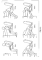
- FIG. 9 shows a crash sequence and the deployment of a tubular airbag.
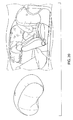
- FIG. 10 shows a side perspective view of an alternate tubular airbag.
- FIG. 11 shows a side plan view of the airbag of FIG. 10 .
- FIG. 12 shows a top plan cross-sectional view of the upper layer of the airbag of FIGS. 10 and 11 , before the tubular structures are stacked or otherwise secured.
- FIG. 13 shows a side view of a crash sequence and the deployment of a tubular airbag of FIGS. 10 and 11 .
- FIG. 14 shows a top view of a crash sequence and the deployment of a tubular airbag of FIGS. 10 and 11 .
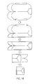
- FIG. 15 shows various sewing and folding configurations for tubular airbags.
- FIG. 16 shows an end plan view of a set of tubular airbags, with a secured junction between the top layer of tubes and the lower layer of tubes.
- FIG. 17 shows an end plan view of a set of tubular airbags, without a secured junction between the top layer of tubes and the lower layer of tubes, but with a side strap in place.
- FIG. 18 shows one particular folding sequence for the tubular airbags.
- FIG. 19 shows a prior art airbag having a spherical balloon shape.
- FIG. 20 shows a prior art airbag having a peanut balloon shape.
- an airbag that reduces the global inflated volume of the airbag. This can require less gas to inflate the bag, allowing the bag to fill more quickly and efficiently. It can also reduce the overall weight of the total airbag system, by allowing use of a smaller inflator. It is also desirable to design airbags having varying shapes, and particularly, shapes that cause the airbag's inflated position to be closer to the occupant. This can improve performance of the airbag (as measured by head injury criteria) by causing the bag to be in earlier contact with the vehicle occupant. It is also desirable to provide an airbag that has a shape and design that allows it to be easier to produce and fold.
- the airbags are provided as inflatable cushions that are made of a tubular shape and oriented in a particular configuration.
- multiple tubular structures are positioned in a generally parallel configuration to one another.
- examples of the present invention provide an airbag that has one or more tubular structures.
- the airbag may be associated with a seat back, such that the airbag deploys backward to support a passenger in a seat behind.
- it may be associated with a steering wheel, a side wall of a vehicle, or any other vehicle structure.
- Airbag 10 is formed from a series of tubular structures 12.
- Tubular structures 12 are formed as individual tubes. They may be fabric tubes, pliable plastic tubes, or any other appropriate material that can be inflated to hold a volume of gas.
- Each tubular structure 12 generally has a length L, a width W, and a height H. The length dimension "L" is greater than the width "W" or the height "H” dimension.
- tubular structures 12 may be formed from top 14 and bottom 16 sheets of material, joined at a seam 18 that extends generally around the perimeter of the structure 12. Joining may be accomplished by stitching, bonding, gluing, or any other appropriate securing or sealing option.
- tubular structures 12 may be otherwise formed.
- a single sheet of material may have its edges sewn or glued together in order to create a single seam on one side, with one (or both) ends sewn or glued together (or overlapped and secured) in order to close the end of tube.
- tubular structures 12 may be formed as having a square, rectangular, triangular, or round or other cross section.
- the term "tubular” is not intended to be restrictive to a particular shape, but is instead intended to refer to a generally elongated tube-like structure that has a hollow interior that can accept a volume of inflation gas.
- the structure may be any shape, as long as it has a length that is greater than either its width or its height, and has an interior hollow area to accept inflation gas.
- Figure 5 illustrates an example wherein the tubular structures are formed as structures having a circular cross-section 27, as opposed to an oval cross-section.
- each structure 12 At one end of each structure 12 is an opening 20 for receiving inflation gas.
- inflation gas is immediately and rapidly pumped into each opening 20 in each structure 12 in order to cause the airbag 10 to inflate and cushion an occupant's forward momentum.
- the tubular airbag 10 requires a lower volume of gas for inflation.
- the bag itself contains requires more material and may have a greater weight than a traditional airbag, the volume of the inflator gas bottle required to fill the airbag can be smaller, so that the overall system has a lower global weight.
- Airbag 10 also requires a smaller volume of gas to inflate than a traditional airbag that is not divided into distinct structures 12, because the use of tubular structures 12 as opposed to a large air bag reduces the total inflated volume of the airbag 10.
- the volume of gas required to fill an airbag 10 in accordance with the present invention, i.e., one that is formed by tubular structures 12, is about 20-25% less than the volume required for a traditional air bag having a similar length and width. According to the below calculation, the volume savings is about 22%:
- the ratio is the following at iso head injuries performance:
- tubular airbag structure provides the following volume calculations which compare a parallelepiped-shaped air bag to the tubular airbags described herein:
- the airbag also allows for the use of a smaller inflator volume compared to the bag performance because of the tube behavior in the very early phase of the occupant body displacement, as shown in Figures 9 and 13-14 .
- the tubes may not, and need not, inflate completely in order for the airbag 10 to be effective, and this can reduce some of the inflation volume required as well.
- each tubular structure Inflation of each tubular structure is manageable in a number of ways.
- the inflation gas may enter each tube individually, such that one fill tube can be directly connected to the inflator while the other structures are filled through this first tube.
- the size of the filling opening on the structure and/or the fill tube may be designed to optimize and manage a desired filling sequence. For example, a bigger opening or a bigger tube is quicker to fill; a smaller opening or a smaller tube is slower to fill.
- a further benefit of the airbag system 10 is that if, for some reason, one of the openings 20 becomes clogged or unworkable or if one of the structures 12 becomes torn or otherwise damaged, there is at least one other tubular structure 12 connected thereto that can still be inflated and provide at least a portion of the desired cushioning effect.
- tubular structures 12 may be sewn to one another along their length L in order to form a roughly rectangular airbag, as shown in Figure 2 .
- Each structure 12 generally has a similar structure, in that the length L (as well as the height H and the width W) of each of the tubular structures is about the same.
- the length may be about 500-700 mm, and in particular example, may be about 600 mm;
- the height may be about 300-400 mm, and in a particular example, may be about 320 mm, ;
- the width may be about 300-400 mm, and in a particular example, may be about 320 mm.
- the height and width will generally be similar, but they need not be identical.
- the structures 12 are secured to one another via a securing system 28.
- Securing system 28 may be formed of any appropriate means, including but not limited to one or more straps 30 configured to secure structures 12 to one another, stitching or sewing the structures 12 to one another, using glue or tape or any other appropriate adhesive or bonding material to secure the structures 12 to one another, using a separate element to secure the structures 12 to one another, or any combination thereof.
- the general goal of securing system is to cause the airbag structures 12 to extend as a unit once inflated. It is preferable that the structures do not spread apart upon inflation, lest they not be effective at catching the vehicle occupant's forward momentum
- the securing system 28 is defined in part by two straps 30, which are secured to ends 32 of each structure 12. Straps 30 cause the structures 12 to extend outwardly (upon inflation) in a collective manner, such that the ends 32 stay close to one another upon airbag deployment, rather than splaying away from one another.
- the airbag of Figure 2 also provides the top two structures 12A and 12B secured to one another via stitching along an internal seam 34 and the bottom two structures 12C and 12D secured to one another via stitching along an internal seam 36.
- Figure 16 shows an end view of a collection of tubular structures that are joined at a junction (where the top and bottom tubular structure contact one another) via stitching, adhesives, welding (such as high frequency welding) or ay other appropriate method that links structures 12 together.
- Figure 17 shows an end view of a collection of tubular structures that are joined via a strap, avoiding a junction point in the middle of the tubes.
- the strap is shown as being a side strap, but it should be understood that the strap may be positioned anywhere along the collection of structures, for each at the front and/or back ends or anywhere along the sides.
- the airbags may be secured in any number of ways, with a junction and a strap, with only a junction, or with only strap.
- an opening 20 of each structure 12 may have a tube 38 extending therefrom.
- Tube 38 is fluidly connected to opening 20 and further provides a fluid connection or link to a gas inflator system.
- Tube 38 may be any desired length or shape. It is generally a connection tube for inflation.
- two or more connection tubes 38 from two or more different tubular structures 12 may be linked together, such that they share a common gas inflator system.
- tubes 38 may remain separate from one another and be connected separately to one or more gas inflator systems. Any appropriate sequence for inflating the tubular structures may be used, and may be dependent upon particular aircraft features and capabilities.
- securing system 28 is formed at least in part by a cushion 40.
- Cushion 40 is secured to ends 32 of tubular structures 12 as a way to (a) keep the ends connected to one another but also to (b) provide a cushioned surface for cushioning the vehicle occupant's forward movement.
- Cushion may be formed from the same or different material that forms tubular structures.
- One or more of the tubular structure ends 32 may be designed to fluidly communicate with cushion 40, such that inflation gas that enters structure 12 extends further into the cushion 40 so that cushion inflates simultaneously.
- cushion 40 may be provided with its own inflation tube, such that cushion is separately inflated.
- Cushion 40 may be provided in any appropriate shape, and is shown in Figure 6 as having a square-like shape, in Figure 7 as having a generally circular shape, and in Figure 8 as having a generally crescent or oval shape. In another example (not shown), cushion may be applied to overlay a top of two tubular structures (e.g., 12A and 12B) in order to form a top layer.
- two tubular structures e.g., 12A and 12B
- Figure 9 illustrates a crash sequence showing the inflation of a tubular airbag 10 and how it braces a vehicle occupant's impact.
- Frame A shows one location where airbag 10 may be secured to a seat back 42. It is generally positioned at face or eye level.
- Frame B shows the airbag in its deployment position. Airbag 10 may begin to deploy immediately upon detection of a crash condition, which is usually within (and often typically before) 100ms of detection of the crash condition. (Any type of wiring, crash sensor system, and inflation system may be used to indicate that a crash condition has occurred and to cause the subsequent inflation of the airbag.)
- Frames C-E illustrate how the tubular airbag 10 prevents the passenger from hitting the seat back 42 (or other vehicle component) in front of the passenger. The sequences may take in total between about 10 to 100ms, depending of the gas flow of the inflator.
- Figures 10-12 show an alternate example of a tubular airbag having structures 12 of varied sizes.
- the structures 12 that form an upper layer 44 are slightly shorter in length than the structures 12 that form the lower layer 46.
- the intent and background of this design is to provide an indented area 48 that can help support a vehicle occupant's face more fully than if all structures are of equal length.
- the upper layer of structures 12 is about 2/3 of the length of the lower layer 46 of structures 12.
- the structures 12 of the upper layer 44 may have a length of about 400-500 mm, and in a particular example, nay be about 440 mm, and the structures 12 of the lower layer 46 may have a length of about 500-700 mm, and in particular example, may be about 600 mm.
- FIG. 12 illustrates a cross-sectional view of the upper layer 44 of the airbag, before the tubular structures are stacked or otherwise secured.
- FIGS 13 and 14 show a side and top view of a similar crash condition.
- the shortened structures are intended to protect the occupant's head at the end of its trajectory.
- This example uses even less gas for inflation of the airbag 10 because of the shortened length of the structure(s) positioned at upper layer 44.
- a tubular airbag comprised of four tubular structures 12 (with the height and width remaining the same, but having varied lengths) is about 20-25% and by certain calculations, about 22% volume less to inflate than a traditional parallelepiped-shaped airbag. This saving in volume allows the use of a smaller inflator which gives a weight reduction of almost 18% in the gas inflator weight.
- the tubular airbags 10 described herein are easier to fold than traditional airbags, as they lay flat. This allows for an accurate folding and a lower package volume.
- the airbags are also able to be sewn with flat sewing seams, with junction of the tube structures by side tethers or straps. Examples of potential folding and sewing configurations are illustrated by Figures 16 and 18 . As shown particularly by Figure 18 , once the tubular airbag is folded, it lays in a substantially flat manner and may be rolled up for stowage.
- tubular structures 12 may be individually formed and secured to one another using any of the various securing systems 28 described herein.
- a top layer of material may be secured to a bottom layer of material with a seam extending the length thereof at the half way point, in order to create two side-by-side structures 12.
- the tubular airbag system is packed into a compartment or opening in a seat back, a steering wheel, or any other component in the vehicle from which an airbag may deploy.
- the attaching system may include one or more tubes 38 extending from an opening in each tubular structures which are intended to attach to an inflation source.
- the method for installing an airbag in a seat may include providing the tubular airbag system, including a system for securing the plurality of tubular structures to one another; providing a system for detecting a crash condition and causing the airbag to deploy; providing an inflation system for inflating the airbag; securing the airbag to the seat; securing the system for detecting a crash condition at a location that enables it to communicate with an activate the airbag upon a crash condition; and securing the system for inflating the airbag to the opening for receiving inflation gas.
- Changes and modifications, additions and deletions may be made to the structures and methods recited above and shown in the drawings without departing from the scope of the invention and the following claims.
Abstract
Description
- Examples of the present invention relate generally to airbags for use in passenger transport vehicles. The airbags are designed to safely interrupt a passenger's forward momentum in the event of a crash condition.
- Airbags are occupant restraining devices, which typically include a flexible envelope or "bag" that is designed to inflate rapidly during a collision in order to prevent the vehicle's occupants from striking interior objects located in front of (or, in some cases, on the side of) the occupant. In automobiles, airbags are designed to prevent occupants from striking the steering wheel, the vehicle door, a window, or any other interior objects. In aircraft, airbags are designed to prevent passengers from striking the seat in front each passenger, the tray tables, a window, or any other interior objects. Airbags on passenger rail cars (such as trains, monorails, trolleys), motorcycles, and other passenger transport vehicles work similarly.
- Most modem vehicles contain multiple airbags. For example, most automobiles provide an airbag in front of each occupant seating position (at least in the front seat), to protect the head and torso. They may also contain knee airbags, which protect the occupant's knees and legs. Most aircraft provide airbags either positioned in the back of each seat (so as to deploy for the passenger sitting behind that seat) or in the seat belts. (For example, passengers sitting in the front seat or bulkhead in the aircraft do not have a seat in front of them, so in this instance, the airbag may be positioned in the passenger seat belt.) Passenger vehicles may also contain airbags in side locations, which can inflate between an occupant and the vehicle door or the vehicle window or wall.
- Typically, sensors deploy one or more airbags in an impact zone at variable rates based on the type and severity of impact. Most airbags are designed to only inflate in moderate to severe frontal crashes. Airbags are normally designed with the intention of supplementing the protection of an occupant who is correctly restrained with a seatbelt.
- Airbags are typically designed as large bags that require a large volume of gas for their inflation. They are typically round in shape, or peanut shaped, examples of which are shown in
Figures 19 and20 . They are often formed by sewing two or three panels together in order to form a balloon or peanut shape. An alternate airbag shape that was designed for side-impact head protection in automobiles is the Inflatable Tubular Structure (ITS) airbag. This system is a single inflatable tube that stows in the vehicle's interior roof-rail. During a crash, the ITS deploys across the side windows to offer a cushioning restraint for the vehicle occupants. - Since their invention in the early 1950's and introduction in the mid-1970's, airbags have continually been improved upon. However, further airbag improvements are desirable, including airbags that have varying designs for varying types of seating arrangements in passenger vehicles.
- Examples of the invention described herein thus provide airbags that are designed to use a lower inflation volume than traditional airbags. In one example, this is accomplished by providing a plurality of tubular airbags secured to one another.
- A tubular airbag system and a tubular airbag for use in a passenger transport system and a method for installing a tubular airbag system in accordance with the present invention are defined by the appended claims.
-
FIG. 1 shows a vehicle occupant being braced by a tubular airbag. -
FIG. 2 shows a side perspective view of a tubular airbag according to one example of this invention. -
FIG. 3 shows a top plan cross-sectional view of the top layer of airbag ofFIG. 2 . -
FIG. 4 a top plan cross-sectional view of an airbag having four tubular structures, before the tubular structures are stacked or otherwise secured. -
FIG. 5 shows a side view schematic of a tubular airbag having tubular structures with a circular cross-section. -
FIG. 6 shows a top plan view of one example of a tubular airbag with a cushion. -
FIG. 7 shows a top perspective view of one example of a tubular airbag with a cushion. -
FIG. 8 shows a top plan view of one example of a tubular airbag with a cushion. -
FIG. 9 shows a crash sequence and the deployment of a tubular airbag. -
FIG. 10 shows a side perspective view of an alternate tubular airbag. -
FIG. 11 shows a side plan view of the airbag ofFIG. 10 . -
FIG. 12 shows a top plan cross-sectional view of the upper layer of the airbag ofFIGS. 10 and 11 , before the tubular structures are stacked or otherwise secured. -
FIG. 13 shows a side view of a crash sequence and the deployment of a tubular airbag ofFIGS. 10 and 11 . -
FIG. 14 shows a top view of a crash sequence and the deployment of a tubular airbag ofFIGS. 10 and 11 . -
FIG. 15 shows various sewing and folding configurations for tubular airbags. -
FIG. 16 shows an end plan view of a set of tubular airbags, with a secured junction between the top layer of tubes and the lower layer of tubes. -
FIG. 17 shows an end plan view of a set of tubular airbags, without a secured junction between the top layer of tubes and the lower layer of tubes, but with a side strap in place. -
FIG. 18 shows one particular folding sequence for the tubular airbags. -
FIG. 19 shows a prior art airbag having a spherical balloon shape. -
FIG. 20 shows a prior art airbag having a peanut balloon shape. - Rather than requiring a large volume of gas to fill a large round airbag, it is desirable to design an airbag that reduces the global inflated volume of the airbag. This can require less gas to inflate the bag, allowing the bag to fill more quickly and efficiently. It can also reduce the overall weight of the total airbag system, by allowing use of a smaller inflator. It is also desirable to design airbags having varying shapes, and particularly, shapes that cause the airbag's inflated position to be closer to the occupant. This can improve performance of the airbag (as measured by head injury criteria) by causing the bag to be in earlier contact with the vehicle occupant. It is also desirable to provide an airbag that has a shape and design that allows it to be easier to produce and fold. These and other advantages are achieved by the tubular airbags of examples of the present invention. The airbags are provided as inflatable cushions that are made of a tubular shape and oriented in a particular configuration. In a specific example, multiple tubular structures are positioned in a generally parallel configuration to one another.
- Accordingly, examples of the present invention provide an airbag that has one or more tubular structures. The airbag may be associated with a seat back, such that the airbag deploys backward to support a passenger in a seat behind. Alternatively, it may be associated with a steering wheel, a side wall of a vehicle, or any other vehicle structure.
- One example of a
tubular airbag 10 is shown inFigures 1 and 2 .Airbag 10 is formed from a series oftubular structures 12.Tubular structures 12 are formed as individual tubes. They may be fabric tubes, pliable plastic tubes, or any other appropriate material that can be inflated to hold a volume of gas. Eachtubular structure 12 generally has a length L, a width W, and a height H. The length dimension "L" is greater than the width "W" or the height "H" dimension. In a particular example,tubular structures 12 may be formed from top 14 and bottom 16 sheets of material, joined at aseam 18 that extends generally around the perimeter of thestructure 12. Joining may be accomplished by stitching, bonding, gluing, or any other appropriate securing or sealing option. However, it should be understood thattubular structures 12 may be otherwise formed. For example, a single sheet of material may have its edges sewn or glued together in order to create a single seam on one side, with one (or both) ends sewn or glued together (or overlapped and secured) in order to close the end of tube. - Although the tubular structures are shown as having a rounded
top surface 22 and arounded bottom surface 24 such that they have an oval-like cross section 26, it should also be understood thattubular structures 12 may be formed as having a square, rectangular, triangular, or round or other cross section. The term "tubular" is not intended to be restrictive to a particular shape, but is instead intended to refer to a generally elongated tube-like structure that has a hollow interior that can accept a volume of inflation gas. The structure may be any shape, as long as it has a length that is greater than either its width or its height, and has an interior hollow area to accept inflation gas.Figure 5 illustrates an example wherein the tubular structures are formed as structures having acircular cross-section 27, as opposed to an oval cross-section. - At one end of each
structure 12 is anopening 20 for receiving inflation gas. In use and during a crash condition, inflation gas is immediately and rapidly pumped into each opening 20 in eachstructure 12 in order to cause theairbag 10 to inflate and cushion an occupant's forward momentum. - One of the benefits of designing the
airbag 10 as having a plurality oftubular structures 12 that are individually inflated rather (simultaneously or one after the other) than one single airbag of the prior art is that thetubular airbag 10 requires a lower volume of gas for inflation. Thus, although the bag itself contains requires more material and may have a greater weight than a traditional airbag, the volume of the inflator gas bottle required to fill the airbag can be smaller, so that the overall system has a lower global weight. The tubular shape reduces the stress on the material, and based on the pressure formula [force=pressure/surface], a lighter and thinner material can also be used to createairbag 10.Airbag 10 also requires a smaller volume of gas to inflate than a traditional airbag that is not divided intodistinct structures 12, because the use oftubular structures 12 as opposed to a large air bag reduces the total inflated volume of theairbag 10. For example, the volume of gas required to fill anairbag 10 in accordance with the present invention, i.e., one that is formed bytubular structures 12, is about 20-25% less than the volume required for a traditional air bag having a similar length and width. According to the below calculation, the volume savings is about 22%: - The ratio is the following at iso head injuries performance:
- 3D bag (which refers to a traditional round airbag) volume is Length x Width x Height so L x W x W when width=height.
- By contrast, the tubular airbag structure provides the following volume calculations which compare a parallelepiped-shaped air bag to the tubular airbags described herein:
- (with heights equivalent) 4 x Length x (Tube diameter x Tube diameter x3.14/4) = As tube diameter is equivalent to half of the Width so 4xLx(W/2xW/2x3.14/4) = LxWxWx3.14/4 so for the same bag behavior in term of protection, there is -22% volume less to inflate (0.785-1*100%) so LxWxWx 0.785 (tubular bag volume) < LxWxW (3d bag volume). A schematic of these comparative dimensions is shown in
Figure 5 . - The airbag also allows for the use of a smaller inflator volume compared to the bag performance because of the tube behavior in the very early phase of the occupant body displacement, as shown in
Figures 9 and13-14 . The tubes may not, and need not, inflate completely in order for theairbag 10 to be effective, and this can reduce some of the inflation volume required as well. - Inflation of each tubular structure is manageable in a number of ways. For example, the inflation gas may enter each tube individually, such that one fill tube can be directly connected to the inflator while the other structures are filled through this first tube. The size of the filling opening on the structure and/or the fill tube may be designed to optimize and manage a desired filling sequence. For example, a bigger opening or a bigger tube is quicker to fill; a smaller opening or a smaller tube is slower to fill. In the example where the tubular structures are provided in a stacked configuration, it may be desirable to first inflate the upper layer of structures, followed by inflation of the lower layer of structures. There may be one, two, more fill tubes used.
- A further benefit of the
airbag system 10 is that if, for some reason, one of theopenings 20 becomes clogged or unworkable or if one of thestructures 12 becomes torn or otherwise damaged, there is at least one othertubular structure 12 connected thereto that can still be inflated and provide at least a portion of the desired cushioning effect. - In one particular example, four
tubular structures 12 may be sewn to one another along their length L in order to form a roughly rectangular airbag, as shown inFigure 2 . Eachstructure 12 generally has a similar structure, in that the length L (as well as the height H and the width W) of each of the tubular structures is about the same. In a particular example, the length may be about 500-700 mm, and in particular example, may be about 600 mm; the height may be about 300-400 mm, and in a particular example, may be about 320 mm, ; and the width may be about 300-400 mm, and in a particular example, may be about 320 mm. The height and width will generally be similar, but they need not be identical. - The
structures 12 are secured to one another via a securingsystem 28. Securingsystem 28 may be formed of any appropriate means, including but not limited to one ormore straps 30 configured to securestructures 12 to one another, stitching or sewing thestructures 12 to one another, using glue or tape or any other appropriate adhesive or bonding material to secure thestructures 12 to one another, using a separate element to secure thestructures 12 to one another, or any combination thereof. The general goal of securing system is to cause theairbag structures 12 to extend as a unit once inflated. It is preferable that the structures do not spread apart upon inflation, lest they not be effective at catching the vehicle occupant's forward momentum - In the example shown in
Figure 2 , the securingsystem 28 is defined in part by twostraps 30, which are secured toends 32 of eachstructure 12.Straps 30 cause thestructures 12 to extend outwardly (upon inflation) in a collective manner, such that the ends 32 stay close to one another upon airbag deployment, rather than splaying away from one another. The airbag ofFigure 2 also provides the top two structures 12A and 12B secured to one another via stitching along aninternal seam 34 and the bottom two structures 12C and 12D secured to one another via stitching along aninternal seam 36. -
Figure 16 shows an end view of a collection of tubular structures that are joined at a junction (where the top and bottom tubular structure contact one another) via stitching, adhesives, welding (such as high frequency welding) or ay other appropriate method that linksstructures 12 together.Figure 17 shows an end view of a collection of tubular structures that are joined via a strap, avoiding a junction point in the middle of the tubes. The strap is shown as being a side strap, but it should be understood that the strap may be positioned anywhere along the collection of structures, for each at the front and/or back ends or anywhere along the sides. The airbags may be secured in any number of ways, with a junction and a strap, with only a junction, or with only strap. - Referring now to
Figures 3 and 4 , anopening 20 of eachstructure 12 may have atube 38 extending therefrom.Tube 38 is fluidly connected to opening 20 and further provides a fluid connection or link to a gas inflator system.Tube 38 may be any desired length or shape. It is generally a connection tube for inflation. As shown inFigure 3 , two ormore connection tubes 38 from two or more differenttubular structures 12 may be linked together, such that they share a common gas inflator system. Alternatively,tubes 38 may remain separate from one another and be connected separately to one or more gas inflator systems. Any appropriate sequence for inflating the tubular structures may be used, and may be dependent upon particular aircraft features and capabilities. - Another form of a securing
system 28 is shown inFigures 6-8 . In these examples, securing system is formed at least in part by acushion 40.Cushion 40 is secured toends 32 oftubular structures 12 as a way to (a) keep the ends connected to one another but also to (b) provide a cushioned surface for cushioning the vehicle occupant's forward movement. Cushion may be formed from the same or different material that forms tubular structures. One or more of the tubular structure ends 32 may be designed to fluidly communicate withcushion 40, such that inflation gas that entersstructure 12 extends further into thecushion 40 so that cushion inflates simultaneously. Alternatively, cushion 40 may be provided with its own inflation tube, such that cushion is separately inflated.Cushion 40 may be provided in any appropriate shape, and is shown inFigure 6 as having a square-like shape, inFigure 7 as having a generally circular shape, and inFigure 8 as having a generally crescent or oval shape. In another example (not shown), cushion may be applied to overlay a top of two tubular structures (e.g., 12A and 12B) in order to form a top layer. -
Figure 9 illustrates a crash sequence showing the inflation of atubular airbag 10 and how it braces a vehicle occupant's impact. Frame A shows one location whereairbag 10 may be secured to a seat back 42. It is generally positioned at face or eye level. Frame B shows the airbag in its deployment position.Airbag 10 may begin to deploy immediately upon detection of a crash condition, which is usually within (and often typically before) 100ms of detection of the crash condition. (Any type of wiring, crash sensor system, and inflation system may be used to indicate that a crash condition has occurred and to cause the subsequent inflation of the airbag.) Frames C-E illustrate how thetubular airbag 10 prevents the passenger from hitting the seat back 42 (or other vehicle component) in front of the passenger. The sequences may take in total between about 10 to 100ms, depending of the gas flow of the inflator. -
Figures 10-12 show an alternate example of a tubularairbag having structures 12 of varied sizes. Thestructures 12 that form anupper layer 44 are slightly shorter in length than thestructures 12 that form thelower layer 46. The intent and background of this design is to provide anindented area 48 that can help support a vehicle occupant's face more fully than if all structures are of equal length. In a specific example, the upper layer ofstructures 12 is about 2/3 of the length of thelower layer 46 ofstructures 12. For example, thestructures 12 of theupper layer 44 may have a length of about 400-500 mm, and in a particular example, nay be about 440 mm, and thestructures 12 of thelower layer 46 may have a length of about 500-700 mm, and in particular example, may be about 600 mm.FIG. 12 illustrates a cross-sectional view of theupper layer 44 of the airbag, before the tubular structures are stacked or otherwise secured. - One example of a crash sequence showing this enhanced support is illustrated in
Figures 13 and14 , which show a side and top view of a similar crash condition. The shortened structures are intended to protect the occupant's head at the end of its trajectory. - This example uses even less gas for inflation of the
airbag 10 because of the shortened length of the structure(s) positioned atupper layer 44. For example, a tubular airbag comprised of four tubular structures 12 (with the height and width remaining the same, but having varied lengths) is about 20-25% and by certain calculations, about 22% volume less to inflate than a traditional parallelepiped-shaped airbag. This saving in volume allows the use of a smaller inflator which gives a weight reduction of almost 18% in the gas inflator weight. - The
tubular airbags 10 described herein are easier to fold than traditional airbags, as they lay flat. This allows for an accurate folding and a lower package volume. The airbags are also able to be sewn with flat sewing seams, with junction of the tube structures by side tethers or straps. Examples of potential folding and sewing configurations are illustrated byFigures 16 and18 . As shown particularly byFigure 18 , once the tubular airbag is folded, it lays in a substantially flat manner and may be rolled up for stowage. - In order to manufacture
tubular airbag 10,tubular structures 12 may be individually formed and secured to one another using any of the various securingsystems 28 described herein. Alternatively, a top layer of material may be secured to a bottom layer of material with a seam extending the length thereof at the half way point, in order to create two side-by-side structures 12. - In use, the tubular airbag system is packed into a compartment or opening in a seat back, a steering wheel, or any other component in the vehicle from which an airbag may deploy. There is provided a system for attaching the tubular airbag system to an interior component of a vehicle. The attaching system may include one or
more tubes 38 extending from an opening in each tubular structures which are intended to attach to an inflation source. - More specifically, the method for installing an airbag in a seat may include providing the tubular airbag system, including a system for securing the plurality of tubular structures to one another; providing a system for detecting a crash condition and causing the airbag to deploy; providing an inflation system for inflating the airbag; securing the airbag to the seat; securing the system for detecting a crash condition at a location that enables it to communicate with an activate the airbag upon a crash condition; and securing the system for inflating the airbag to the opening for receiving inflation gas.
Changes and modifications, additions and deletions may be made to the structures and methods recited above and shown in the drawings without departing from the scope of the invention and the following claims.
Claims (12)
- A tubular airbag system for use in a passenger transport vehicle, comprising an airbag (10);
characterized in that:(a) the airbag (10) is tubular, comprising a plurality of inflatable tubular structures (12, ), each tubular structure having a length dimension that is greater than its width or height dimension and an opening (20) for receiving inflation gas; and(b) a system (28) for securing the plurality of tubular structures to one another. - The tubular airbag system of claim 1, further comprising a system (38) for delivering inflation gas to the tubular airbag system.
- The tubular airbag system of claim 1 or claim 2, further comprising a cushion (40) secured to the tubular airbag (10).
- The tubular airbag system of any of claims 1 to 3, wherein the system (28) for securing the plurality of airbags (12) to one another comprises:one or more straps (30);and/or,a series of sewn stitches, high frequency welding, or adhesives.
- The tubular airbag system of any of claims 1 to 4, further comprising a system (38) for attaching the tubular airbag system (10) to an interior component (42) of a vehicle.
- The tubular airbag system of claim 5, wherein the system for attaching the tubular airbag system (10) to an interior component (42) of a vehicle comprises one or more tubes (38) extending from the opening (20) in each tubular structure which are intended to attach to an inflation source.
- The tubular airbag system of any of claims 1 to 6, further comprising a source of inflation gas in fluid communication with each tubular structure (12).
- The tubular airbag system of any of claims 1 to 7, installed on a seat back (42) of an aircraft seat.
- The tubular airbag system of any of claims 1 to 8, comprising four tubular structures (12), with two tubular structures (12a,12b) forming an upper layer and two tubular structures (12c, 12d) forming a lower layer.
- The tubular airbag system of any of claims 1 to 9, wherein the plurality of tubular structures (12) form an upper layer (44) and a lower layer (46), wherein one or more tubular structures comprising the upper layer have a length that is shorter than one or more tubular structures comprising the lower layer.
- A tubular airbag for a tubular airbag system as claimed in any of claims 1 to 10.
- A method for installing a tubular airbag system in a seat, comprising:(a) providing a tubular airbag as claimed in claim 11;(b) providing a tubular airbag system as claimed in any of claims 1 to 10;(c) providing a system for detecting a crash condition and causing the airbag to deploy; and(d) securing the system for detecting a crash condition at a location that enables it to communicate with an activate the airbag upon a crash condition.
Applications Claiming Priority (2)
| Application Number | Priority Date | Filing Date | Title |
|---|---|---|---|
| US201161545641P | 2011-10-11 | 2011-10-11 | |
| US13/428,100 US20130088056A1 (en) | 2011-10-11 | 2012-03-23 | Tubular airbag |
Publications (2)
| Publication Number | Publication Date |
|---|---|
| EP2581276A1 true EP2581276A1 (en) | 2013-04-17 |
| EP2581276B1 EP2581276B1 (en) | 2015-10-21 |
Family
ID=46044426
Family Applications (1)
| Application Number | Title | Priority Date | Filing Date |
|---|---|---|---|
| EP12165076.6A Active EP2581276B1 (en) | 2011-10-11 | 2012-04-20 | Tubular Airbag |
Country Status (2)
| Country | Link |
|---|---|
| US (1) | US20130088056A1 (en) |
| EP (1) | EP2581276B1 (en) |
Cited By (9)
| Publication number | Priority date | Publication date | Assignee | Title |
|---|---|---|---|---|
| WO2015165592A1 (en) * | 2014-04-30 | 2015-11-05 | Trw Automotive Gmbh | Inflatable airbag for protecting a person, and airbag module, vehicle parts and vehicle occupant restraint system having such an airbag |
| WO2017001361A1 (en) * | 2015-07-02 | 2017-01-05 | Trw Automotive Gmbh | Inflatable airbag for protecting a person, airbag module, vehicle occupant restraining system comprising such an airbag, and method for producing an inflatable airbag |
| WO2017008015A1 (en) * | 2015-07-08 | 2017-01-12 | B/E Aerospace, Inc. | Aircraft passenger restraint system with three-point seat belt and structural mounted airbag |
| US9889937B2 (en) | 2012-03-19 | 2018-02-13 | Amsafe, Inc. | Structure mounted airbag assemblies and associated systems and methods |
| US9925950B2 (en) | 2015-04-11 | 2018-03-27 | Amsafe, Inc. | Active airbag vent system |
| US9944245B2 (en) | 2015-03-28 | 2018-04-17 | Amsafe, Inc. | Extending pass-through airbag occupant restraint systems, and associated systems and methods |
| GB2555910A (en) * | 2016-08-22 | 2018-05-16 | Ford Global Tech Llc | Airbag including a plurality of fingers extending from an impact surface |
| US10604259B2 (en) | 2016-01-20 | 2020-03-31 | Amsafe, Inc. | Occupant restraint systems having extending restraints, and associated systems and methods |
| WO2023012187A1 (en) * | 2021-08-05 | 2023-02-09 | Mercedes-Benz Group AG | Airbag device for arranging on a backrest part of a moveable seat device of a motor vehicle, and seat device |
Families Citing this family (20)
| Publication number | Priority date | Publication date | Assignee | Title |
|---|---|---|---|---|
| US8556291B2 (en) * | 2011-07-06 | 2013-10-15 | Zodiac Seats France | Airbag in privacy wall |
| US9511866B2 (en) * | 2012-03-19 | 2016-12-06 | Amsafe, Inc. | Structure mounted airbag assemblies and associated systems and methods |
| US9428132B2 (en) | 2012-06-07 | 2016-08-30 | Zodiac Seats France | Aircraft airbag system |
| US9102300B2 (en) * | 2014-01-03 | 2015-08-11 | Ford Global Technologies, Llc | Vehicle occupant restraint system |
| EP2905185B1 (en) * | 2014-02-06 | 2018-03-14 | Autoliv Development AB | Motor vehicle with an airbag between a wheel and the car body and airbag unit |
| US10843651B2 (en) * | 2014-04-30 | 2020-11-24 | Schroth Safety Products Llc | Monument mounted airbag |
| US9821913B1 (en) * | 2014-04-30 | 2017-11-21 | Schroth Safety Products Llc | Monument mounted airbag |
| DE102014113277A1 (en) * | 2014-09-15 | 2016-03-17 | Recaro Aircraft Seating Gmbh & Co. Kg | Aircraft seat device |
| DE102014013649B4 (en) * | 2014-09-19 | 2023-08-10 | Zf Airbag Germany Gmbh | Adaptive, deployable restraint element for a vehicle safety system, gas bag module and vehicle safety system with such a restraint element and use of the fin jet effect in an adaptive restraint system |
| US9352839B2 (en) * | 2014-10-02 | 2016-05-31 | Amsafe, Inc. | Active positioning airbag assembly and associated systems and methods |
| CN105235629A (en) * | 2015-10-21 | 2016-01-13 | 芜湖金鹏汽车部件有限公司 | Spring type columnar automobile airbag |
| JP6613855B2 (en) * | 2015-12-04 | 2019-12-04 | トヨタ自動車株式会社 | Rear seat occupant protection airbag device for vehicle |
| US10960845B2 (en) | 2016-10-10 | 2021-03-30 | Key Safety Systems, Inc. | Curved airbag and method of manufacturing |
| JP6438996B2 (en) * | 2017-03-27 | 2018-12-19 | 株式会社Subaru | Crew protection device |
| US10703321B2 (en) * | 2017-11-20 | 2020-07-07 | Ford Global Technologies, Llc | Airbag assembly |
| US20190161045A1 (en) * | 2017-11-29 | 2019-05-30 | GM Global Technology Operations LLC | Airbag assembly configured to deploy from a side wall of a vehicle to resist upward motion of the leg of an occupant, and a system and method for controlling the airbag assembly |
| KR102064843B1 (en) * | 2018-04-23 | 2020-01-10 | 아우토리브 디벨롭먼트 아베 | Airbag apparatus of vehicle |
| US11440663B2 (en) * | 2019-01-29 | 2022-09-13 | The Boeing Company | Inflatable pod systems on a aircraft and methods for inflating the inflatable pod systems |
| US10967829B1 (en) | 2019-09-17 | 2021-04-06 | Joyson Safety Systems Acquisition Llc | Driver side airbag module |
| US20210214092A1 (en) * | 2020-01-09 | 2021-07-15 | Amsafe, Inc. | Structure mounted airbag systems |
Citations (6)
| Publication number | Priority date | Publication date | Assignee | Title |
|---|---|---|---|---|
| US3731949A (en) * | 1971-05-12 | 1973-05-08 | Allied Chem | Flat bag made of tubular sections |
| US3747952A (en) * | 1971-09-17 | 1973-07-24 | R Graebe | Protective device |
| GB1362672A (en) * | 1970-07-31 | 1974-08-07 | Nissan Motor | Vehicular safety device |
| GB2289653A (en) * | 1994-05-23 | 1995-11-29 | Automotive Tech Int | Airbag(s) made of plastic film - for head, knee, or child restraint |
| US20070252367A1 (en) * | 2004-11-30 | 2007-11-01 | Zhihua Zhong | Sandwiched tubular airbags |
| EP2077207A1 (en) * | 2006-10-19 | 2009-07-08 | Takata Corporation | Occupant restraint device |
Family Cites Families (13)
| Publication number | Priority date | Publication date | Assignee | Title |
|---|---|---|---|---|
| US3603535A (en) * | 1968-11-13 | 1971-09-07 | Maurice Depolo | Lifesaving support system |
| CA957404A (en) * | 1970-11-24 | 1974-11-05 | Isao Maeda | Rapidly inflatable impact cushioning device for high-speed travelling vehicle |
| JPS5168044A (en) * | 1974-12-09 | 1976-06-12 | Nippon Soken | |
| US4261535A (en) * | 1979-10-05 | 1981-04-14 | The United States Of America As Represented By The Secretary Of The Air Force | Streamline afterbody for an ejection seat |
| US4500114A (en) * | 1982-08-27 | 1985-02-19 | Thiokol Corporation | Device for controlled differential flow |
| US4803744A (en) * | 1987-05-19 | 1989-02-14 | Hill-Rom Company, Inc. | Inflatable bed |
| US5044030A (en) * | 1990-06-06 | 1991-09-03 | Fabrico Manufacturing Corporation | Multiple layer fluid-containing cushion |
| US5542695A (en) * | 1993-12-28 | 1996-08-06 | R. Stresau Laboratory, Inc. | Air bag deployment system |
| US5727270A (en) * | 1995-06-07 | 1998-03-17 | Airceltec Inc. | Valveless self sealing fluid or gas container |
| US7188862B2 (en) * | 2004-03-17 | 2007-03-13 | Delphi Technologies, Inc | Apparatus and method for controlling an inflatable cushion |
| EP1516785A1 (en) * | 2003-09-18 | 2005-03-23 | Michael Cohen | Air bags |
| US9099012B2 (en) * | 2005-03-14 | 2015-08-04 | Cubic Corporation | Adjustment of altitude measurements |
| DE102006038124B4 (en) * | 2006-08-14 | 2019-05-23 | Daimler Ag | Restraint system for a motor vehicle |
-
2012
- 2012-03-23 US US13/428,100 patent/US20130088056A1/en not_active Abandoned
- 2012-04-20 EP EP12165076.6A patent/EP2581276B1/en active Active
Patent Citations (6)
| Publication number | Priority date | Publication date | Assignee | Title |
|---|---|---|---|---|
| GB1362672A (en) * | 1970-07-31 | 1974-08-07 | Nissan Motor | Vehicular safety device |
| US3731949A (en) * | 1971-05-12 | 1973-05-08 | Allied Chem | Flat bag made of tubular sections |
| US3747952A (en) * | 1971-09-17 | 1973-07-24 | R Graebe | Protective device |
| GB2289653A (en) * | 1994-05-23 | 1995-11-29 | Automotive Tech Int | Airbag(s) made of plastic film - for head, knee, or child restraint |
| US20070252367A1 (en) * | 2004-11-30 | 2007-11-01 | Zhihua Zhong | Sandwiched tubular airbags |
| EP2077207A1 (en) * | 2006-10-19 | 2009-07-08 | Takata Corporation | Occupant restraint device |
Cited By (11)
| Publication number | Priority date | Publication date | Assignee | Title |
|---|---|---|---|---|
| US9889937B2 (en) | 2012-03-19 | 2018-02-13 | Amsafe, Inc. | Structure mounted airbag assemblies and associated systems and methods |
| WO2015165592A1 (en) * | 2014-04-30 | 2015-11-05 | Trw Automotive Gmbh | Inflatable airbag for protecting a person, and airbag module, vehicle parts and vehicle occupant restraint system having such an airbag |
| US9944245B2 (en) | 2015-03-28 | 2018-04-17 | Amsafe, Inc. | Extending pass-through airbag occupant restraint systems, and associated systems and methods |
| US9925950B2 (en) | 2015-04-11 | 2018-03-27 | Amsafe, Inc. | Active airbag vent system |
| WO2017001361A1 (en) * | 2015-07-02 | 2017-01-05 | Trw Automotive Gmbh | Inflatable airbag for protecting a person, airbag module, vehicle occupant restraining system comprising such an airbag, and method for producing an inflatable airbag |
| CN107848486A (en) * | 2015-07-02 | 2018-03-27 | Trw汽车股份有限公司 | For protecting the inflatable air-bag of people, the vehicle occupant restraint system of air bag module including this air bag and the method for manufacturing inflatable air-bag |
| CN107848486B (en) * | 2015-07-02 | 2021-01-08 | Trw汽车股份有限公司 | Inflatable airbag for protecting a person, airbag module, vehicle occupant restraint system comprising such an airbag and method of manufacturing an inflatable airbag |
| WO2017008015A1 (en) * | 2015-07-08 | 2017-01-12 | B/E Aerospace, Inc. | Aircraft passenger restraint system with three-point seat belt and structural mounted airbag |
| US10604259B2 (en) | 2016-01-20 | 2020-03-31 | Amsafe, Inc. | Occupant restraint systems having extending restraints, and associated systems and methods |
| GB2555910A (en) * | 2016-08-22 | 2018-05-16 | Ford Global Tech Llc | Airbag including a plurality of fingers extending from an impact surface |
| WO2023012187A1 (en) * | 2021-08-05 | 2023-02-09 | Mercedes-Benz Group AG | Airbag device for arranging on a backrest part of a moveable seat device of a motor vehicle, and seat device |
Also Published As
| Publication number | Publication date |
|---|---|
| EP2581276B1 (en) | 2015-10-21 |
| US20130088056A1 (en) | 2013-04-11 |
Similar Documents
| Publication | Publication Date | Title |
|---|---|---|
| EP2581276B1 (en) | Tubular Airbag | |
| US20160001735A1 (en) | Tubular airbag | |
| JP6734880B2 (en) | Cost-effective use of integrally molded woven fabrics for curtain airbags | |
| CN108068745B (en) | Vehicle seat assembly including an airbag | |
| CN109476272B (en) | Front airbag assembly for reducing rotational velocity of occupant's head | |
| US7665761B1 (en) | Inflatable personal restraint systems and associated methods of use and manufacture | |
| US8944461B2 (en) | Airbag in privacy wall | |
| US8622417B1 (en) | Airbag with low-volume structure | |
| JP5123941B2 (en) | Side curtain airbag with extended shoulder | |
| JP6681893B2 (en) | Airbag module | |
| US20180111581A1 (en) | Frontal airbag assemblies for reducing rotational velocity of a head of an occupant | |
| JP5003631B2 (en) | Side airbag device | |
| JP4075463B2 (en) | Head protection airbag and head protection airbag device | |
| US20050206138A1 (en) | Airbag device | |
| US7946619B2 (en) | Airbag | |
| KR20160074649A (en) | Wrap around side impact airbag systems and methods | |
| EP2543556B1 (en) | Deviating airbag | |
| JP2011025909A (en) | Side airbag device | |
| WO2017177718A1 (en) | Vehicle seat | |
| KR101637205B1 (en) | Lateral airbag for vehicle | |
| US9415742B1 (en) | Three-way gas guide | |
| JP6039931B2 (en) | Airbag device | |
| US20230182675A1 (en) | Inflatable curtain airbag with bi-roll package state | |
| JP5724908B2 (en) | Side airbag device |
Legal Events
| Date | Code | Title | Description |
|---|---|---|---|
| PUAI | Public reference made under article 153(3) epc to a published international application that has entered the european phase |
Free format text: ORIGINAL CODE: 0009012 |
|
| AK | Designated contracting states |
Kind code of ref document: A1 Designated state(s): AL AT BE BG CH CY CZ DE DK EE ES FI FR GB GR HR HU IE IS IT LI LT LU LV MC MK MT NL NO PL PT RO RS SE SI SK SM TR |
|
| AX | Request for extension of the european patent |
Extension state: BA ME |
|
| RAP1 | Party data changed (applicant data changed or rights of an application transferred) |
Owner name: ZODIAC SEATS FRANCE |
|
| 17P | Request for examination filed |
Effective date: 20131017 |
|
| RBV | Designated contracting states (corrected) |
Designated state(s): AL AT BE BG CH CY CZ DE DK EE ES FI FR GB GR HR HU IE IS IT LI LT LU LV MC MK MT NL NO PL PT RO RS SE SI SK SM TR |
|
| 17Q | First examination report despatched |
Effective date: 20140121 |
|
| REG | Reference to a national code |
Ref country code: DE Ref legal event code: R079 Ref document number: 602012011720 Country of ref document: DE Free format text: PREVIOUS MAIN CLASS: B60R0021233000 Ipc: B60R0021233800 |
|
| RIC1 | Information provided on ipc code assigned before grant |
Ipc: B60R 21/2338 20110101AFI20150324BHEP Ipc: B60R 21/231 20110101ALI20150324BHEP Ipc: B60R 21/233 20060101ALI20150324BHEP |
|
| GRAP | Despatch of communication of intention to grant a patent |
Free format text: ORIGINAL CODE: EPIDOSNIGR1 |
|
| INTG | Intention to grant announced |
Effective date: 20150515 |
|
| GRAS | Grant fee paid |
Free format text: ORIGINAL CODE: EPIDOSNIGR3 |
|
| GRAA | (expected) grant |
Free format text: ORIGINAL CODE: 0009210 |
|
| AK | Designated contracting states |
Kind code of ref document: B1 Designated state(s): AL AT BE BG CH CY CZ DE DK EE ES FI FR GB GR HR HU IE IS IT LI LT LU LV MC MK MT NL NO PL PT RO RS SE SI SK SM TR |
|
| REG | Reference to a national code |
Ref country code: GB Ref legal event code: FG4D Ref country code: NL Ref legal event code: MP Effective date: 20151021 |
|
| REG | Reference to a national code |
Ref country code: CH Ref legal event code: EP |
|
| REG | Reference to a national code |
Ref country code: AT Ref legal event code: REF Ref document number: 756391 Country of ref document: AT Kind code of ref document: T Effective date: 20151115 |
|
| REG | Reference to a national code |
Ref country code: IE Ref legal event code: FG4D |
|
| REG | Reference to a national code |
Ref country code: DE Ref legal event code: R096 Ref document number: 602012011720 Country of ref document: DE |
|
| REG | Reference to a national code |
Ref country code: LT Ref legal event code: MG4D |
|
| REG | Reference to a national code |
Ref country code: AT Ref legal event code: MK05 Ref document number: 756391 Country of ref document: AT Kind code of ref document: T Effective date: 20151021 |
|
| REG | Reference to a national code |
Ref country code: FR Ref legal event code: PLFP Year of fee payment: 5 |
|
| PG25 | Lapsed in a contracting state [announced via postgrant information from national office to epo] |
Ref country code: ES Free format text: LAPSE BECAUSE OF FAILURE TO SUBMIT A TRANSLATION OF THE DESCRIPTION OR TO PAY THE FEE WITHIN THE PRESCRIBED TIME-LIMIT Effective date: 20151021 Ref country code: NO Free format text: LAPSE BECAUSE OF FAILURE TO SUBMIT A TRANSLATION OF THE DESCRIPTION OR TO PAY THE FEE WITHIN THE PRESCRIBED TIME-LIMIT Effective date: 20160121 Ref country code: HR Free format text: LAPSE BECAUSE OF FAILURE TO SUBMIT A TRANSLATION OF THE DESCRIPTION OR TO PAY THE FEE WITHIN THE PRESCRIBED TIME-LIMIT Effective date: 20151021 Ref country code: NL Free format text: LAPSE BECAUSE OF FAILURE TO SUBMIT A TRANSLATION OF THE DESCRIPTION OR TO PAY THE FEE WITHIN THE PRESCRIBED TIME-LIMIT Effective date: 20151021 Ref country code: LT Free format text: LAPSE BECAUSE OF FAILURE TO SUBMIT A TRANSLATION OF THE DESCRIPTION OR TO PAY THE FEE WITHIN THE PRESCRIBED TIME-LIMIT Effective date: 20151021 Ref country code: IS Free format text: LAPSE BECAUSE OF FAILURE TO SUBMIT A TRANSLATION OF THE DESCRIPTION OR TO PAY THE FEE WITHIN THE PRESCRIBED TIME-LIMIT Effective date: 20160221 |
|
| PG25 | Lapsed in a contracting state [announced via postgrant information from national office to epo] |
Ref country code: SE Free format text: LAPSE BECAUSE OF FAILURE TO SUBMIT A TRANSLATION OF THE DESCRIPTION OR TO PAY THE FEE WITHIN THE PRESCRIBED TIME-LIMIT Effective date: 20151021 Ref country code: RS Free format text: LAPSE BECAUSE OF FAILURE TO SUBMIT A TRANSLATION OF THE DESCRIPTION OR TO PAY THE FEE WITHIN THE PRESCRIBED TIME-LIMIT Effective date: 20151021 Ref country code: FI Free format text: LAPSE BECAUSE OF FAILURE TO SUBMIT A TRANSLATION OF THE DESCRIPTION OR TO PAY THE FEE WITHIN THE PRESCRIBED TIME-LIMIT Effective date: 20151021 Ref country code: LV Free format text: LAPSE BECAUSE OF FAILURE TO SUBMIT A TRANSLATION OF THE DESCRIPTION OR TO PAY THE FEE WITHIN THE PRESCRIBED TIME-LIMIT Effective date: 20151021 Ref country code: PL Free format text: LAPSE BECAUSE OF FAILURE TO SUBMIT A TRANSLATION OF THE DESCRIPTION OR TO PAY THE FEE WITHIN THE PRESCRIBED TIME-LIMIT Effective date: 20151021 Ref country code: AT Free format text: LAPSE BECAUSE OF FAILURE TO SUBMIT A TRANSLATION OF THE DESCRIPTION OR TO PAY THE FEE WITHIN THE PRESCRIBED TIME-LIMIT Effective date: 20151021 Ref country code: GR Free format text: LAPSE BECAUSE OF FAILURE TO SUBMIT A TRANSLATION OF THE DESCRIPTION OR TO PAY THE FEE WITHIN THE PRESCRIBED TIME-LIMIT Effective date: 20160122 Ref country code: PT Free format text: LAPSE BECAUSE OF FAILURE TO SUBMIT A TRANSLATION OF THE DESCRIPTION OR TO PAY THE FEE WITHIN THE PRESCRIBED TIME-LIMIT Effective date: 20160222 |
|
| REG | Reference to a national code |
Ref country code: DE Ref legal event code: R097 Ref document number: 602012011720 Country of ref document: DE |
|
| PG25 | Lapsed in a contracting state [announced via postgrant information from national office to epo] |
Ref country code: CZ Free format text: LAPSE BECAUSE OF FAILURE TO SUBMIT A TRANSLATION OF THE DESCRIPTION OR TO PAY THE FEE WITHIN THE PRESCRIBED TIME-LIMIT Effective date: 20151021 |
|
| PLBE | No opposition filed within time limit |
Free format text: ORIGINAL CODE: 0009261 |
|
| STAA | Information on the status of an ep patent application or granted ep patent |
Free format text: STATUS: NO OPPOSITION FILED WITHIN TIME LIMIT |
|
| PG25 | Lapsed in a contracting state [announced via postgrant information from national office to epo] |
Ref country code: RO Free format text: LAPSE BECAUSE OF FAILURE TO SUBMIT A TRANSLATION OF THE DESCRIPTION OR TO PAY THE FEE WITHIN THE PRESCRIBED TIME-LIMIT Effective date: 20151021 Ref country code: SM Free format text: LAPSE BECAUSE OF FAILURE TO SUBMIT A TRANSLATION OF THE DESCRIPTION OR TO PAY THE FEE WITHIN THE PRESCRIBED TIME-LIMIT Effective date: 20151021 Ref country code: EE Free format text: LAPSE BECAUSE OF FAILURE TO SUBMIT A TRANSLATION OF THE DESCRIPTION OR TO PAY THE FEE WITHIN THE PRESCRIBED TIME-LIMIT Effective date: 20151021 Ref country code: BE Free format text: LAPSE BECAUSE OF NON-PAYMENT OF DUE FEES Effective date: 20160430 Ref country code: SK Free format text: LAPSE BECAUSE OF FAILURE TO SUBMIT A TRANSLATION OF THE DESCRIPTION OR TO PAY THE FEE WITHIN THE PRESCRIBED TIME-LIMIT Effective date: 20151021 Ref country code: DK Free format text: LAPSE BECAUSE OF FAILURE TO SUBMIT A TRANSLATION OF THE DESCRIPTION OR TO PAY THE FEE WITHIN THE PRESCRIBED TIME-LIMIT Effective date: 20151021 |
|
| 26N | No opposition filed |
Effective date: 20160722 |
|
| PG25 | Lapsed in a contracting state [announced via postgrant information from national office to epo] |
Ref country code: SI Free format text: LAPSE BECAUSE OF FAILURE TO SUBMIT A TRANSLATION OF THE DESCRIPTION OR TO PAY THE FEE WITHIN THE PRESCRIBED TIME-LIMIT Effective date: 20151021 |
|
| REG | Reference to a national code |
Ref country code: CH Ref legal event code: PL |
|
| PG25 | Lapsed in a contracting state [announced via postgrant information from national office to epo] |
Ref country code: LU Free format text: LAPSE BECAUSE OF FAILURE TO SUBMIT A TRANSLATION OF THE DESCRIPTION OR TO PAY THE FEE WITHIN THE PRESCRIBED TIME-LIMIT Effective date: 20160420 Ref country code: BE Free format text: LAPSE BECAUSE OF FAILURE TO SUBMIT A TRANSLATION OF THE DESCRIPTION OR TO PAY THE FEE WITHIN THE PRESCRIBED TIME-LIMIT Effective date: 20151021 |
|
| PG25 | Lapsed in a contracting state [announced via postgrant information from national office to epo] |
Ref country code: CH Free format text: LAPSE BECAUSE OF NON-PAYMENT OF DUE FEES Effective date: 20160430 Ref country code: LI Free format text: LAPSE BECAUSE OF NON-PAYMENT OF DUE FEES Effective date: 20160430 |
|
| REG | Reference to a national code |
Ref country code: FR Ref legal event code: PLFP Year of fee payment: 6 |
|
| REG | Reference to a national code |
Ref country code: FR Ref legal event code: PLFP Year of fee payment: 7 |
|
| PG25 | Lapsed in a contracting state [announced via postgrant information from national office to epo] |
Ref country code: HU Free format text: LAPSE BECAUSE OF FAILURE TO SUBMIT A TRANSLATION OF THE DESCRIPTION OR TO PAY THE FEE WITHIN THE PRESCRIBED TIME-LIMIT; INVALID AB INITIO Effective date: 20120420 Ref country code: CY Free format text: LAPSE BECAUSE OF FAILURE TO SUBMIT A TRANSLATION OF THE DESCRIPTION OR TO PAY THE FEE WITHIN THE PRESCRIBED TIME-LIMIT Effective date: 20151021 |
|
| PG25 | Lapsed in a contracting state [announced via postgrant information from national office to epo] |
Ref country code: MK Free format text: LAPSE BECAUSE OF FAILURE TO SUBMIT A TRANSLATION OF THE DESCRIPTION OR TO PAY THE FEE WITHIN THE PRESCRIBED TIME-LIMIT Effective date: 20151021 Ref country code: TR Free format text: LAPSE BECAUSE OF FAILURE TO SUBMIT A TRANSLATION OF THE DESCRIPTION OR TO PAY THE FEE WITHIN THE PRESCRIBED TIME-LIMIT Effective date: 20151021 Ref country code: MC Free format text: LAPSE BECAUSE OF FAILURE TO SUBMIT A TRANSLATION OF THE DESCRIPTION OR TO PAY THE FEE WITHIN THE PRESCRIBED TIME-LIMIT Effective date: 20151021 Ref country code: MT Free format text: LAPSE BECAUSE OF NON-PAYMENT OF DUE FEES Effective date: 20160430 |
|
| PG25 | Lapsed in a contracting state [announced via postgrant information from national office to epo] |
Ref country code: BG Free format text: LAPSE BECAUSE OF FAILURE TO SUBMIT A TRANSLATION OF THE DESCRIPTION OR TO PAY THE FEE WITHIN THE PRESCRIBED TIME-LIMIT Effective date: 20151021 |
|
| PG25 | Lapsed in a contracting state [announced via postgrant information from national office to epo] |
Ref country code: AL Free format text: LAPSE BECAUSE OF FAILURE TO SUBMIT A TRANSLATION OF THE DESCRIPTION OR TO PAY THE FEE WITHIN THE PRESCRIBED TIME-LIMIT Effective date: 20151021 |
|
| REG | Reference to a national code |
Ref country code: IE Ref legal event code: MM4A |
|
| PG25 | Lapsed in a contracting state [announced via postgrant information from national office to epo] |
Ref country code: IE Free format text: LAPSE BECAUSE OF NON-PAYMENT OF DUE FEES Effective date: 20180420 |
|
| REG | Reference to a national code |
Ref country code: DE Ref legal event code: R082 Ref document number: 602012011720 Country of ref document: DE Representative=s name: GODEMEYER BLUM LENZE PATENTANWAELTE, PARTNERSC, DE Ref country code: DE Ref legal event code: R081 Ref document number: 602012011720 Country of ref document: DE Owner name: SAFRAN SEATS S.A., FR Free format text: FORMER OWNER: ZODIAC SEATS FRANCE, ISSOUDUN, FR |
|
| REG | Reference to a national code |
Ref country code: DE Ref legal event code: R081 Ref document number: 602012011720 Country of ref document: DE Owner name: SAFRAN SEATS S.A., FR Free format text: FORMER OWNER: SAFRAN SEATS, PLAISIR, FR Ref country code: DE Ref legal event code: R082 Ref document number: 602012011720 Country of ref document: DE Representative=s name: GODEMEYER BLUM LENZE PATENTANWAELTE, PARTNERSC, DE |
|
| PGFP | Annual fee paid to national office [announced via postgrant information from national office to epo] |
Ref country code: FR Payment date: 20230321 Year of fee payment: 12 |
|
| PGFP | Annual fee paid to national office [announced via postgrant information from national office to epo] |
Ref country code: IT Payment date: 20230322 Year of fee payment: 12 Ref country code: GB Payment date: 20230321 Year of fee payment: 12 |
|
| PGFP | Annual fee paid to national office [announced via postgrant information from national office to epo] |
Ref country code: DE Payment date: 20230321 Year of fee payment: 12 |