EP2581246A1 - Vehicle door structure - Google Patents
Vehicle door structure Download PDFInfo
- Publication number
- EP2581246A1 EP2581246A1 EP11792395.3A EP11792395A EP2581246A1 EP 2581246 A1 EP2581246 A1 EP 2581246A1 EP 11792395 A EP11792395 A EP 11792395A EP 2581246 A1 EP2581246 A1 EP 2581246A1
- Authority
- EP
- European Patent Office
- Prior art keywords
- width direction
- vehicle width
- wall portion
- door
- vehicle
- Prior art date
- Legal status (The legal status is an assumption and is not a legal conclusion. Google has not performed a legal analysis and makes no representation as to the accuracy of the status listed.)
- Granted
Links
Images


Classifications
-
- B—PERFORMING OPERATIONS; TRANSPORTING
- B60—VEHICLES IN GENERAL
- B60J—WINDOWS, WINDSCREENS, NON-FIXED ROOFS, DOORS, OR SIMILAR DEVICES FOR VEHICLES; REMOVABLE EXTERNAL PROTECTIVE COVERINGS SPECIALLY ADAPTED FOR VEHICLES
- B60J5/00—Doors
- B60J5/04—Doors arranged at the vehicle sides
- B60J5/042—Reinforcement elements
- B60J5/0422—Elongated type elements, e.g. beams, cables, belts or wires
- B60J5/0423—Elongated type elements, e.g. beams, cables, belts or wires characterised by position in the lower door structure
- B60J5/0425—Elongated type elements, e.g. beams, cables, belts or wires characterised by position in the lower door structure the elements being arranged essentially horizontal in the centre of the lower door structure
-
- B—PERFORMING OPERATIONS; TRANSPORTING
- B60—VEHICLES IN GENERAL
- B60J—WINDOWS, WINDSCREENS, NON-FIXED ROOFS, DOORS, OR SIMILAR DEVICES FOR VEHICLES; REMOVABLE EXTERNAL PROTECTIVE COVERINGS SPECIALLY ADAPTED FOR VEHICLES
- B60J5/00—Doors
- B60J5/04—Doors arranged at the vehicle sides
- B60J5/042—Reinforcement elements
- B60J5/0422—Elongated type elements, e.g. beams, cables, belts or wires
- B60J5/0423—Elongated type elements, e.g. beams, cables, belts or wires characterised by position in the lower door structure
- B60J5/0433—Elongated type elements, e.g. beams, cables, belts or wires characterised by position in the lower door structure the elements being arranged at the lock area
-
- B—PERFORMING OPERATIONS; TRANSPORTING
- B60—VEHICLES IN GENERAL
- B60J—WINDOWS, WINDSCREENS, NON-FIXED ROOFS, DOORS, OR SIMILAR DEVICES FOR VEHICLES; REMOVABLE EXTERNAL PROTECTIVE COVERINGS SPECIALLY ADAPTED FOR VEHICLES
- B60J5/00—Doors
- B60J5/04—Doors arranged at the vehicle sides
- B60J5/042—Reinforcement elements
- B60J5/0456—Behaviour during impact
- B60J5/0461—Behaviour during impact characterised by a pre-defined mode of deformation or displacement in order to absorb impact
-
- E—FIXED CONSTRUCTIONS
- E05—LOCKS; KEYS; WINDOW OR DOOR FITTINGS; SAFES
- E05B—LOCKS; ACCESSORIES THEREFOR; HANDCUFFS
- E05B77/00—Vehicle locks characterised by special functions or purposes
- E05B77/02—Vehicle locks characterised by special functions or purposes for accident situations
-
- E—FIXED CONSTRUCTIONS
- E05—LOCKS; KEYS; WINDOW OR DOOR FITTINGS; SAFES
- E05B—LOCKS; ACCESSORIES THEREFOR; HANDCUFFS
- E05B79/00—Mounting or connecting vehicle locks or parts thereof
- E05B79/10—Connections between movable lock parts
- E05B79/20—Connections between movable lock parts using flexible connections, e.g. Bowden cables
Definitions
- the present invention relates to a vehicle door structure.
- a latch device is provided at an end portion of the door. In a state where the door is closed, the latch device is engaged with a lock striker provided on a vehicle body side.
- the outside handle is connected to the latch device through a wire or the like. Accordingly, when the outside handle is turned, tension acts on the wire, disengaging the latch device and the lock striker from each other, and thus the door can be opened.
- the present invention provides a vehicle door structure preventing a door from opening, with a simple structure, even when a certain load toward an inner side of the vehicle is inputted to an outside handle.
- the present invention is a vehicle door structure in which: an outside handle is turnably supported on a door outer panel; a movable member capable of moving together with turn of the outside handle is provided on a door side; a latch device configured to engage and disengage a door with and from a vehicle body works in conjunction with the movement of the movable member; and a reinforcing member is arranged between the door outer panel and a door inner panel.
- a vehicle width direction wall portion and a front-rear direction wall portion are formed in the reinforcing member, the vehicle width direction wall portion extending in a vehicle width direction, the front-rear direction wall portion bending from an inner end, in the vehicle width direction, of the vehicle width direction wall portion and extending in a vehicle front-rear direction.
- a locking member is provided on the front-rear direction wall portion at a portion facing the movable member.
- the vehicle width direction wall portion of the reinforcing member when a load is inputted from a lateral side to the door, the vehicle width direction wall portion of the reinforcing member is deformed to be bent in such a way as to fall in the vehicle front-rear direction. For this reason, the outward deformation of the vehicle width direction wall portion in the vehicle width direction is suppressed, and the locking member provided on the front-rear direction wall portion is deformed and moved inward in the vehicle width direction to be locked to the movable member, thereby preventing the movement of the movable member.
- the present invention can prevent the door from opening, with a simple door structure, even when a certain load toward an inner side of the vehicle is inputted to the outside handle.
- a pair of left and right front doors (doors) 1 are openably and closably arranged on both left and right sides of a vehicle.
- Three members are arranged on a door inner panel 3 in a vehicle front-rear direction in order to improve rigidity of each front door 1.
- a reinforcement panel 5 is arranged at a door waist portion on the upper side
- a stiffener 7 is arranged at the center in a top-bottom direction
- an impact beam 9 is arranged on the lower side.
- an outside handle 11 is turnably attached to a door outer panel 57 not illustrated through a door handle attachment member 13.
- an upper bead portion 15 and a lower bead portion 17 are formed in a vertical pair on an upper side and a lower side of the stiffener 7, respectively.
- a locking member 23, which is formed separately from the stiffener 7 as will be described later, is joined to a rear end portion of the stiffener 7. Note that a wire 19 extending from the outside handle 11 is connected to a door lock device 21.
- a rear end portion of the stiffener 7 includes: a vehicle width direction wall portion 29 which bends inward in a vehicle width direction at a bending portion 27 located at an outer end in the vehicle width direction and extends in the vehicle width direction to an inner end in the vehicle width direction; and a front-rear direction wall portion 33 which bends at a vehicle width direction inner end 31 of the vehicle width direction wall portion 29 and extends rearward.
- a rear end 35 of the front-rear direction wall portion 33 is linked to a rear end of the door inner panel 3 with bolts B.
- a top-bottom width dimension of the vehicle width direction wall portion 29 of the stiffener 7 is set to be gradually reduced toward an inner side in the vehicle width direction, and to be the minimum at the vehicle width direction inner end 31.
- the vehicle width direction wall portion 29 is formed to satisfy W0 > W1.
- the upper bead portion (bead portion) 15 is provided to extend in the vehicle width direction on the upper side
- the lower bead portion (bead portion) 17 is provided to extend in the vehicle width direction on the lower side.
- these upper bead portion 15 and lower bead portion 17 continue to the vehicle width direction inner end 31, and are not formed in the front-rear direction wall portion 33.
- the top-bottom width dimension is set to be the minimum at the vehicle width direction inner end 31, and the upper bead portion 15 and the lower bead portion 17 are provided to extend to the vehicle width direction inner end 31.
- the vehicle width direction inner end 31 is formed as a fragile portion.
- rigidity of the vehicle width direction wall portion 29 is improved by the upper bead portion 15 and the lower bead portion 17 while rigidity of the front-rear direction wall portion 33 is improved by linking the locking member 23 thereto, and thus the vehicle width direction inner end 31 is a fragile portion which is easily bent.
- an end portion of the wire 19 is supported with a hook 51 provided on the door lock device 21, and a tip end of the wire 19 is fixed to a wire supporting portion 53 of the lock lever 25.
- the lock lever 25 is supported on the door lock device 21 turnably in the top-bottom direction.
- a latch device not illustrated is provided to the door lock device 21, and a lock striker not illustrated is provided on a vehicle body side facing the latch device. In a closed state where the front door 1 is closed, the latch device and the lock striker are engaged with each other.
- the lock lever 25 turns upward to disengage the latch device (not illustrated) and the lock striker (not illustrated) from each other, thereby opening the front door 1.
- the locking member 23 which is separate from the stiffener 7 is attached to the front-rear direction wall portion 33 of the stiffener 7 with bolts B at positions facing the wire supporting portion 53 of the lock lever (movable member) 25.
- the locking member 23 is processed to be bent in a hat-section shape, and a claw portion 55 is bent and extends inward in the vehicle width direction at an upper end of the locking member 23.
- a height position of the claw portion 55 is disposed slightly higher than the wire supporting portion 53 of the lock lever 25 in the state where the front door 1 is closed.
- the lock lever 25 is supported on the door lock device 21 turnably in the top-bottom direction.
- the front-rear direction wall portion 33 of the stiffener 7 is disposed close to and facing the lock lever 25.
- a spherical buckle member 54 is attached to a tip end of the wire 19.
- a tubular supporting tool 58 is fitted to a locking piece 56 at a tip end of the wire supporting portion 53. The supporting tool 58 is open downward, and the buckle member 54 is locked to the supporting tool 58.
- the vehicle width direction wall portion 29 is deformed to be bent in a substantially Z section shape as shown in Part (a) of Fig. 8 , with the vehicle width direction inner end 31 and the bending portion 27 as origins.
- the locking member 23 is attached to the front-rear direction wall portion 33.
- the locking member 23 approaches the lock lever 25 by deformation and movement of the front-rear direction wall portion 33, so that a tip end of the claw portion 55 is locked to the locking piece 56 from above. In this way, upward movement of the lock lever 25 is prevented.
- the lock lever 25 does not turn. Accordingly, the latch device and the lock striker remain engaged, thereby preventing the front door 1 from opening.
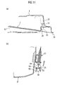
- a comparative example will be described with reference to Figs. 10 and 11 .
- the locking member 23 according to the present invention is not provided. Note that, in Figs. 10 and 11 , portions having the same structure as those of the embodiment are denoted by the same reference numerals, and a description thereof will be omitted.
- the vehicle width direction wall portion 29 extending in the vehicle width direction and the front-rear direction wall portion 33 extending in the vehicle front-rear direction from the vehicle width direction inner end 31 of the vehicle width direction wall portion 29 are formed, and the locking member 23 is provided on the front-rear direction wall portion 33 at a portion facing the lock lever (movable member) 25.
- the vehicle width direction wall portion 29 of the stiffener 7 is deformed to be bent in such a way as to fall in the vehicle front-rear direction. For this reason, the outward deformation of the vehicle width direction wall portion 29 in the vehicle width direction is suppressed, and the locking member 23 provided on the front-rear direction wall portion 33 is deformed and moved inward in the vehicle width direction, thereby preventing the movement of the lock lever 25.
- the present invention can prevent the front door 1 from opening, with a simple door structure, even when a certain load toward an inner side of the vehicle is inputted to the outside handle 11.
- the locking member 23 is formed separately from the front-rear direction wall portion 33. Accordingly, since the front-rear direction wall portion 33 is reinforced by the locking member 23, the outward deformation of the vehicle width direction wall portion 29 in the vehicle width direction can be further suppressed.
- the upper bead portion 15 and the lower bead portion 17 extending to the vehicle width direction inner end 31 are provided to the vehicle width direction wall portion 29, and thus the vehicle width direction inner end 31 is formed as a fragile portion. Hence, when a load is inputted from a lateral side to the front door 1, the bending deformation of the vehicle width direction wall portion 29 is further facilitated.
- the vehicle width direction wall portion 29 is formed to have a top-bottom width dimension gradually reduced toward an inner side in the vehicle width direction, and to be the minimum at the vehicle width direction inner end 31. Hence, when a load is inputted from a lateral side to the front door 1, the bending deformation of the vehicle width direction wall portion 29 is further facilitated.
- a vehicle door structure according to the present invention can prevent a door from opening, with a simple door structure, even when a certain load toward an inner side of the vehicle is inputted to an outside handle.
Landscapes
- Engineering & Computer Science (AREA)
- Mechanical Engineering (AREA)
- Lock And Its Accessories (AREA)
Abstract
Description
- The present invention relates to a vehicle door structure.
- Conventionally, as shown in Japanese Patent Application Publication No.
Hei 10(1998)-266642 - A latch device is provided at an end portion of the door. In a state where the door is closed, the latch device is engaged with a lock striker provided on a vehicle body side.
- In addition, the outside handle is connected to the latch device through a wire or the like. Accordingly, when the outside handle is turned, tension acts on the wire, disengaging the latch device and the lock striker from each other, and thus the door can be opened.
- However, in such a conventional door structure, a separate device needs to be provided to prevent the door from opening when a certain load toward an inner side of the vehicle is inputted to the outside handle. For this reason, an internal structure of the door becomes complicated, causing an increase in cost.
- Accordingly, the present invention provides a vehicle door structure preventing a door from opening, with a simple structure, even when a certain load toward an inner side of the vehicle is inputted to an outside handle.
- The present invention is a vehicle door structure in which: an outside handle is turnably supported on a door outer panel; a movable member capable of moving together with turn of the outside handle is provided on a door side; a latch device configured to engage and disengage a door with and from a vehicle body works in conjunction with the movement of the movable member; and a reinforcing member is arranged between the door outer panel and a door inner panel. A vehicle width direction wall portion and a front-rear direction wall portion are formed in the reinforcing member, the vehicle width direction wall portion extending in a vehicle width direction, the front-rear direction wall portion bending from an inner end, in the vehicle width direction, of the vehicle width direction wall portion and extending in a vehicle front-rear direction. Additionally, a locking member is provided on the front-rear direction wall portion at a portion facing the movable member.
- In the vehicle door structure according to the present invention, when a load is inputted from a lateral side to the door, the vehicle width direction wall portion of the reinforcing member is deformed to be bent in such a way as to fall in the vehicle front-rear direction. For this reason, the outward deformation of the vehicle width direction wall portion in the vehicle width direction is suppressed, and the locking member provided on the front-rear direction wall portion is deformed and moved inward in the vehicle width direction to be locked to the movable member, thereby preventing the movement of the movable member. Hence, even when the load is transmitted to the outside handle, the engagement between the door and the vehicle body by the latch device is maintained and thus the door does not open. As described above, the present invention can prevent the door from opening, with a simple door structure, even when a certain load toward an inner side of the vehicle is inputted to the outside handle.
-
- [
Fig. 1] Fig. 1 is a side view of a front door employing a door structure according to an embodiment of the present invention, where a door outer panel is omitted. - [
Fig. 2] Fig. 2 is a side view enlarging a main portion ofFig. 1 . - [
Fig. 3] Fig. 3 is a cross-sectional view taken along an X-X line ofFig. 2 . - [
Fig. 4] Fig. 4 is a side view of a stiffener according to the embodiment viewed from the rear of the vehicle. - [
Fig. 5] Fig. 5 is a perspective view ofFig. 2 viewed obliquely from the front, and shows a state where the stiffener is deformed upon input of a load toward an inner side in a vehicle width direction. - [
Fig. 6] Fig. 6 is a cross-sectional view of the front door according to the embodiment. - [
Fig. 7 ] Parts (a) and (b) ofFig. 7 correspond to a cross-sectional view taken along a Y-Y line ofFig. 5 and a cross-sectional view taken along a Z-Z line ofFig. 5 , respectively, and show a normal state before deformation. - [
Fig. 8 ] Parts (a) and (b) ofFig. 8 correspond to a cross-sectional view taken along the Y-Y line ofFig. 5 and a cross-sectional view taken along the Z-Z line ofFig. 5 , respectively, and show a middle stage where the door outer panel and the stiffener are deformed upon input of a load toward an inner side in the vehicle width direction. - [
Fig. 9] Fig. 9 is a cross-sectional view of the front door with the door outer panel and the stiffener being deformed upon input of the load toward the inner side in the vehicle width direction, and shows a final stage of the deformation. - [
Fig. 10] Fig. 10 is a cross-sectional view of a front door according to a comparative example. Parts (a) and (b) ofFig. 10 correspond to a cross-sectional view taken along the Y-Y line ofFig. 5 and a cross-sectional view taken along the Z-Z line ofFig. 5 , respectively, and show a normal state before deformation. - [
Fig. 11] Fig. 11 is a cross-sectional view of the front door according to the comparative example. Parts (a) and (b) ofFig. 11 correspond to a cross-sectional view taken along the Y-Y line ofFig. 5 and a cross-sectional view taken along the Z-Z line ofFig. 5 , respectively, and show a state after the deformation. - An embodiment of the present invention will be described below in detail with reference to the drawings.
- As shown in
Fig. 1 , a pair of left and right front doors (doors) 1 are openably and closably arranged on both left and right sides of a vehicle. Three members are arranged on a doorinner panel 3 in a vehicle front-rear direction in order to improve rigidity of each front door 1. To be specific, areinforcement panel 5 is arranged at a door waist portion on the upper side, a stiffener 7 (reinforcing member) is arranged at the center in a top-bottom direction, and animpact beam 9 is arranged on the lower side. - In addition, as shown in
Figs 1 and2 , at an end portion below thereinforcement panel 5 and closer to the rear side of the vehicle, anoutside handle 11 is turnably attached to a doorouter panel 57 not illustrated through a doorhandle attachment member 13. Moreover, as shown inFig 2 , anupper bead portion 15 and alower bead portion 17 are formed in a vertical pair on an upper side and a lower side of thestiffener 7, respectively. Alocking member 23, which is formed separately from thestiffener 7 as will be described later, is joined to a rear end portion of thestiffener 7. Note that awire 19 extending from theoutside handle 11 is connected to adoor lock device 21. - As shown in
Fig. 3 , thedoor lock device 21 which has an inverse L shape in a plan view is arranged at a corner portion on a rear end side of the doorinner panel 3, and a lock lever (movable member) 25 is turnably supported on thedoor lock device 21. In addition, a rear end portion of thestiffener 7 includes: a vehicle widthdirection wall portion 29 which bends inward in a vehicle width direction at abending portion 27 located at an outer end in the vehicle width direction and extends in the vehicle width direction to an inner end in the vehicle width direction; and a front-reardirection wall portion 33 which bends at a vehicle width directioninner end 31 of the vehicle widthdirection wall portion 29 and extends rearward. Arear end 35 of the front-reardirection wall portion 33 is linked to a rear end of the doorinner panel 3 with bolts B. - As shown in
Fig. 4 , a top-bottom width dimension of the vehicle widthdirection wall portion 29 of thestiffener 7 is set to be gradually reduced toward an inner side in the vehicle width direction, and to be the minimum at the vehicle width directioninner end 31. In other words, when a top-bottom width of the vehicle widthdirection wall portion 29 at thebending portion 27 is W0, and a top-bottom width of the vehicle widthdirection wall portion 29 at the vehicle width directioninner end 31 is W1, the vehicle widthdirection wall portion 29 is formed to satisfy W0 > W1. Additionally, in the vehicle widthdirection wall portion 29, the upper bead portion (bead portion) 15 is provided to extend in the vehicle width direction on the upper side, and the lower bead portion (bead portion) 17 is provided to extend in the vehicle width direction on the lower side. Incidentally, theseupper bead portion 15 andlower bead portion 17 continue to the vehicle width directioninner end 31, and are not formed in the front-reardirection wall portion 33. - As described above, in the vehicle width
direction wall portion 29, the top-bottom width dimension is set to be the minimum at the vehicle width directioninner end 31, and theupper bead portion 15 and thelower bead portion 17 are provided to extend to the vehicle width directioninner end 31. Thus, the vehicle width directioninner end 31 is formed as a fragile portion. In other words, rigidity of the vehicle widthdirection wall portion 29 is improved by theupper bead portion 15 and thelower bead portion 17 while rigidity of the front-reardirection wall portion 33 is improved by linking thelocking member 23 thereto, and thus the vehicle width directioninner end 31 is a fragile portion which is easily bent. - As shown in
Fig. 5 , an end portion of thewire 19 is supported with ahook 51 provided on thedoor lock device 21, and a tip end of thewire 19 is fixed to awire supporting portion 53 of thelock lever 25. Thelock lever 25 is supported on thedoor lock device 21 turnably in the top-bottom direction. On the other hand, a latch device not illustrated is provided to thedoor lock device 21, and a lock striker not illustrated is provided on a vehicle body side facing the latch device. In a closed state where the front door 1 is closed, the latch device and the lock striker are engaged with each other. Accordingly, when tension acts on thewire 19 by pulling theoutside handle 11, thelock lever 25 turns upward to disengage the latch device (not illustrated) and the lock striker (not illustrated) from each other, thereby opening the front door 1. In addition, as shown inFig. 5 , thelocking member 23 which is separate from thestiffener 7 is attached to the front-reardirection wall portion 33 of thestiffener 7 with bolts B at positions facing thewire supporting portion 53 of the lock lever (movable member) 25. Specifically, thelocking member 23 is processed to be bent in a hat-section shape, and aclaw portion 55 is bent and extends inward in the vehicle width direction at an upper end of thelocking member 23. A height position of theclaw portion 55 is disposed slightly higher than thewire supporting portion 53 of thelock lever 25 in the state where the front door 1 is closed. Hence, as will be described in detail later, when thelocking member 23 is moved inward in the vehicle width direction as a result of deformation of thestiffener 7, theclaw portion 55 of thelocking member 23 holds thewire supporting portion 53 of thelock lever 25 from above to prevent the turn of thelock lever 25. - Next, a description will be given of the deformation behavior when a lateral load is inputted to the front door 1 (see
Fig. 6 ) according to the embodiment. - As shown in
Figs. 6 and7 , in a normal state where the front door 1 is closed and a load is yet to be inputted to the front door 1, thelock lever 25 is supported on thedoor lock device 21 turnably in the top-bottom direction. On an outer side of thelock lever 25 in the vehicle width direction, the front-reardirection wall portion 33 of thestiffener 7 is disposed close to and facing thelock lever 25. Note that, as shown in Part (b) ofFig. 7 , aspherical buckle member 54 is attached to a tip end of thewire 19. On the other hand, a tubular supportingtool 58 is fitted to alocking piece 56 at a tip end of thewire supporting portion 53. The supportingtool 58 is open downward, and thebuckle member 54 is locked to the supportingtool 58. - As shown in Part (a) of
Fig. 8 , when a load from an outer side to an inner side in the vehicle width direction is inputted to the doorouter panel 57 and theoutside handle 11, the doorouter panel 57 is deformed in such a way that a front portion of the doorouter panel 57 turns inward in the vehicle width direction about arear end portion 59 thereof which is joined to the doorinner panel 3. In addition, thestiffener 7 is also deformed and moved inward in the vehicle width direction as a result of being pushed by the doorouter panel 57. Incidentally, therear end 35 of thestiffener 7 is linked to the doorinner panel 3 as described above. Hence, the vehicle widthdirection wall portion 29 is deformed to be bent in a substantially Z section shape as shown in Part (a) ofFig. 8 , with the vehicle width directioninner end 31 and the bendingportion 27 as origins. In addition, the lockingmember 23 is attached to the front-reardirection wall portion 33. For this reason, as shown in Part (b) ofFig. 8 , the lockingmember 23 approaches thelock lever 25 by deformation and movement of the front-reardirection wall portion 33, so that a tip end of theclaw portion 55 is locked to thelocking piece 56 from above. In this way, upward movement of thelock lever 25 is prevented. Thus, even when a certain load is inputted from a lateral side to theoutside handle 11, thelock lever 25 does not turn. Accordingly, the latch device and the lock striker remain engaged, thereby preventing the front door 1 from opening. - Moreover, even in a state where the deformation is further advanced as shown in
Fig. 9 , the above-mentioned state in Part (b) ofFig. 8 is kept and the latch device and the lock striker remain engaged, thereby preventing the front door 1 from opening. - Next, a comparative example will be described with reference to
Figs. 10 and11 . In the comparative example, the lockingmember 23 according to the present invention is not provided. Note that, inFigs. 10 and11 , portions having the same structure as those of the embodiment are denoted by the same reference numerals, and a description thereof will be omitted. - As shown in Parts (a) and (b) of
Figs. 10 , in a normal state where a load is yet to be inputted to the doorouter panel 57 and theoutside handle 11, thelock lever 25 is disposed at a lower end position. - Then, as shown in Part (a) of
Fig. 11 , when a load is inputted to the doorouter panel 57 and theoutside handle 11, thelock lever 25 is moved upward as shown in Part (b) ofFig. 11 . In this way, the latch device and the lock striker is disengaged from each other, thereby opening the front door 1. - Operations and effects according to the embodiment will be described below.
- (1) In the
stiffener 7 serving as a reinforcing member, the vehicle widthdirection wall portion 29 extending in the vehicle width direction and the front-reardirection wall portion 33 extending in the vehicle front-rear direction from the vehicle width directioninner end 31 of the vehicle widthdirection wall portion 29 are formed, and the lockingmember 23 is provided on the front-reardirection wall portion 33 at a portion facing the lock lever (movable member) 25. - Accordingly, when a load is inputted from a lateral side to the front door 1, the vehicle width
direction wall portion 29 of thestiffener 7 is deformed to be bent in such a way as to fall in the vehicle front-rear direction. For this reason, the outward deformation of the vehicle widthdirection wall portion 29 in the vehicle width direction is suppressed, and the lockingmember 23 provided on the front-reardirection wall portion 33 is deformed and moved inward in the vehicle width direction, thereby preventing the movement of thelock lever 25. Hence, even when the load is transmitted to theoutside handle 11, the engagement between the front door 1 and the vehicle body by the latch device is maintained and thus the front door 1 does not open. As described above, the present invention can prevent the front door 1 from opening, with a simple door structure, even when a certain load toward an inner side of the vehicle is inputted to theoutside handle 11. - (2) The locking
member 23 is formed separately from the front-reardirection wall portion 33. Accordingly, since the front-reardirection wall portion 33 is reinforced by the lockingmember 23, the outward deformation of the vehicle widthdirection wall portion 29 in the vehicle width direction can be further suppressed. - (3) The
upper bead portion 15 and thelower bead portion 17 extending to the vehicle width directioninner end 31 are provided to the vehicle widthdirection wall portion 29, and thus the vehicle width directioninner end 31 is formed as a fragile portion. Hence, when a load is inputted from a lateral side to the front door 1, the bending deformation of the vehicle widthdirection wall portion 29 is further facilitated. - (4) The vehicle width
direction wall portion 29 is formed to have a top-bottom width dimension gradually reduced toward an inner side in the vehicle width direction, and to be the minimum at the vehicle width directioninner end 31. Hence, when a load is inputted from a lateral side to the front door 1, the bending deformation of the vehicle widthdirection wall portion 29 is further facilitated. - A vehicle door structure according to the present invention can prevent a door from opening, with a simple door structure, even when a certain load toward an inner side of the vehicle is inputted to an outside handle.
Claims (4)
- A vehicle door structure comprising:an outside handle turnably provided to a door outer panel;a movable member provided on a door side and being capable of moving together with turn of the outside handle;a latch device configured to engage and disengage a door with and from a vehicle body in conjunction with the movement of the movable member; anda reinforcing member provided between the door outer panel and a door inner panel, whereina vehicle width direction wall portion and a front-rear direction wall portion are formed in the reinforcing member, the vehicle width direction wall portion extending in a vehicle width direction, the front-rear direction wall portion bending from an inner end, in the vehicle width direction, of the vehicle width direction wall portion and extending in a vehicle front-rear direction, anda locking member is provided on the front-rear direction wall portion at a portion facing the movable member.
- The vehicle door structure according to claim 1, wherein the locking member is formed separately from the front-rear direction wall portion.
- The vehicle door structure according to claim 1 or 2, wherein the inner end in the vehicle width direction is formed as a fragile portion by providing the vehicle width direction wall portion with a bead portion extending to the inner end in the vehicle width direction.
- The vehicle door structure according to any one of claims 1 to 3, wherein a top-bottom width dimension of the vehicle width direction wall portion is set to be gradually reduced toward an inner side in the vehicle width direction.
Applications Claiming Priority (2)
| Application Number | Priority Date | Filing Date | Title |
|---|---|---|---|
| JP2010130853 | 2010-06-08 | ||
| PCT/JP2011/062925 WO2011155438A1 (en) | 2010-06-08 | 2011-06-06 | Vehicle door structure |
Publications (3)
| Publication Number | Publication Date |
|---|---|
| EP2581246A1 true EP2581246A1 (en) | 2013-04-17 |
| EP2581246A4 EP2581246A4 (en) | 2017-12-06 |
| EP2581246B1 EP2581246B1 (en) | 2019-08-07 |
Family
ID=45098045
Family Applications (1)
| Application Number | Title | Priority Date | Filing Date |
|---|---|---|---|
| EP11792395.3A Active EP2581246B1 (en) | 2010-06-08 | 2011-06-06 | Vehicle door structure |
Country Status (9)
| Country | Link |
|---|---|
| US (1) | US8955257B2 (en) |
| EP (1) | EP2581246B1 (en) |
| JP (1) | JP5403159B2 (en) |
| CN (1) | CN102917899B (en) |
| BR (1) | BR112012031173B1 (en) |
| MX (1) | MX2012013366A (en) |
| MY (1) | MY166989A (en) |
| RU (1) | RU2519165C1 (en) |
| WO (1) | WO2011155438A1 (en) |
Cited By (2)
| Publication number | Priority date | Publication date | Assignee | Title |
|---|---|---|---|---|
| US11608659B2 (en) | 2020-01-31 | 2023-03-21 | Nissan North America, Inc. | Vehicle door assembly |
| US12172501B2 (en) | 2022-04-22 | 2024-12-24 | Nissan North America, Inc. | Vehicle door assembly |
Families Citing this family (19)
| Publication number | Priority date | Publication date | Assignee | Title |
|---|---|---|---|---|
| BR112015008856B1 (en) * | 2012-10-29 | 2021-11-03 | Aisin Seiki Kabushiki Kaisha | VEHICLE DOOR LOCK DEVICE |
| JP2016048011A (en) * | 2014-08-28 | 2016-04-07 | トヨタ車体株式会社 | Vehicle door lock release device |
| CN107614304B (en) * | 2015-05-27 | 2019-04-23 | 日产自动车株式会社 | Vehicle door structure |
| US9487066B1 (en) | 2015-07-07 | 2016-11-08 | Toyota Motor Engineering & Manufacturing North America, Inc. | Deformable side impact bar |
| DE102015226654A1 (en) * | 2015-12-23 | 2017-06-29 | Volkswagen Aktiengesellschaft | Device for mechanically preventing an automatic opening of a vehicle door and vehicle with such a device |
| US10676970B2 (en) * | 2017-04-05 | 2020-06-09 | Toyota Motor Engineering & Manufacturing North America, Inc. | Protection block for vehicle door lock |
| JP6765351B2 (en) * | 2017-07-12 | 2020-10-07 | 本田技研工業株式会社 | Vehicle door structure |
| US10526817B2 (en) * | 2017-11-06 | 2020-01-07 | Toyota Motor Engineering & Manufacturing North America, Inc. | Disabling system for a lock rod in a vehicle door's locking system |
| JP6744881B2 (en) * | 2018-02-20 | 2020-08-19 | 三井金属アクト株式会社 | Door latch device for automobile |
| US11060326B2 (en) * | 2018-03-16 | 2021-07-13 | Toyota Motor Engineering & Manufacturing North America, Inc. | Door latch assemblies for vehicles including latch release lever blocking structures |
| KR102621230B1 (en) * | 2019-01-24 | 2024-01-05 | 현대자동차 주식회사 | Door for vehicle |
| US10864805B2 (en) * | 2019-01-25 | 2020-12-15 | Nissan North America, Inc. | Energy absorber for vehicle doors |
| WO2020190282A1 (en) * | 2019-03-19 | 2020-09-24 | Nissan North America, Inc | Vehicle door asssembly |
| US11065945B2 (en) * | 2019-06-05 | 2021-07-20 | Nissan North America, Inc. | Vehicle door structure |
| US11560738B2 (en) * | 2019-06-28 | 2023-01-24 | Nissan North America, Inc. | Door lock assembly for a vehicle door panel |
| JP7392588B2 (en) * | 2020-06-24 | 2023-12-06 | スズキ株式会社 | vehicle door structure |
| JP2024060546A (en) * | 2022-10-19 | 2024-05-02 | 株式会社Subaru | Vehicle Doors |
| US12460452B2 (en) * | 2023-09-07 | 2025-11-04 | Ferrari S.P.A. | Door for a motor vehicle |
| US12497805B2 (en) * | 2024-05-21 | 2025-12-16 | Toyota Motor Engineering & Manufacturing North America, Inc. | Vehicle door assembly including a door latch stopper bracket |
Family Cites Families (22)
| Publication number | Priority date | Publication date | Assignee | Title |
|---|---|---|---|---|
| SU385020A1 (en) | 1970-11-20 | 1973-05-29 | Московский ордена Трудового Красного Знамени автомобильный завод имени Ленинского комсомола | DRIVE VEHICLE LOCKS |
| US3713691A (en) * | 1971-02-10 | 1973-01-30 | J Bayless | Vehicle door collision plate and latch |
| JPS6055672B2 (en) * | 1979-05-10 | 1985-12-06 | アイシン精機株式会社 | Automobile door lock device |
| AT391453B (en) * | 1986-11-10 | 1990-10-10 | Austria Metall | PROFILE CARRIERS, ESPECIALLY BUMPER PROTECTOR CARRIERS FOR SIDE DOORS AND WALLS OF MOTOR VEHICLE BODIES |
| US5253906A (en) * | 1992-05-04 | 1993-10-19 | General Motors Corporation | Linkage for vehicle door latch |
| JP3486070B2 (en) | 1997-03-21 | 2004-01-13 | 株式会社ホンダロック | Vehicle Out-Handle Device |
| JP3947278B2 (en) | 1997-09-10 | 2007-07-18 | 富士重工業株式会社 | Vehicle door unlock mechanism |
| ES2329038T3 (en) | 1997-12-12 | 2009-11-20 | John Phillip Chevalier | LOCK ASSEMBLIES FOR CAR DOORS OR OTHER CLOSURES. |
| JP4451108B2 (en) * | 2003-10-08 | 2010-04-14 | ダイハツ工業株式会社 | Vehicle door lock device |
| US7364211B2 (en) * | 2003-11-13 | 2008-04-29 | Intier Automotive Closures Inc. | Vehicle lock controlled by a shape memory alloy actuator |
| JP4492211B2 (en) * | 2004-05-19 | 2010-06-30 | 三菱自動車エンジニアリング株式会社 | Vehicle door opening prevention structure |
| JP4560776B2 (en) | 2004-09-10 | 2010-10-13 | スズキ株式会社 | Door open state prevention structure |
| JP4526359B2 (en) * | 2004-11-25 | 2010-08-18 | ダイハツ工業株式会社 | Vehicle door |
| JP2006233456A (en) * | 2005-02-22 | 2006-09-07 | Aisin Seiki Co Ltd | Door lock device |
| US7648192B2 (en) * | 2005-08-02 | 2010-01-19 | Ford Global Technologies, Llc | Door latch system for automotive vehicle |
| JP4640127B2 (en) * | 2005-11-15 | 2011-03-02 | 日産自動車株式会社 | Door waist structure |
| KR100862257B1 (en) * | 2007-12-13 | 2008-10-09 | 현대자동차주식회사 | Car door lock prevention device in case of collision |
| US8360486B2 (en) * | 2008-11-05 | 2013-01-29 | GM Global Technology Operations LLC | Vehicle side door assembly |
| JP2010253836A (en) | 2009-04-27 | 2010-11-11 | Bridgestone Corp | Method for manufacturing pneumatic tire, and pneumatic tire |
| US8235451B2 (en) * | 2009-11-16 | 2012-08-07 | Toyota Motor Engineering & Manufacturing North America, Inc. | Method and system for deforming a drive rod in a door after an impact to the door |
| US8387311B2 (en) * | 2010-04-21 | 2013-03-05 | Honda Motor Co., Ltd. | Vehicle door assembly for preventing opening of the door during outer handle intrusion event |
| US8414038B2 (en) * | 2010-08-12 | 2013-04-09 | Nissan North America, Inc. | Vehicle door latch structure |
-
2011
- 2011-06-06 MX MX2012013366A patent/MX2012013366A/en active IP Right Grant
- 2011-06-06 WO PCT/JP2011/062925 patent/WO2011155438A1/en not_active Ceased
- 2011-06-06 CN CN201180027029.3A patent/CN102917899B/en active Active
- 2011-06-06 MY MYPI2012005237A patent/MY166989A/en unknown
- 2011-06-06 RU RU2012158125/11A patent/RU2519165C1/en active
- 2011-06-06 BR BR112012031173-5A patent/BR112012031173B1/en active IP Right Grant
- 2011-06-06 US US13/702,352 patent/US8955257B2/en active Active
- 2011-06-06 JP JP2012519372A patent/JP5403159B2/en active Active
- 2011-06-06 EP EP11792395.3A patent/EP2581246B1/en active Active
Non-Patent Citations (1)
| Title |
|---|
| See references of WO2011155438A1 * |
Cited By (2)
| Publication number | Priority date | Publication date | Assignee | Title |
|---|---|---|---|---|
| US11608659B2 (en) | 2020-01-31 | 2023-03-21 | Nissan North America, Inc. | Vehicle door assembly |
| US12172501B2 (en) | 2022-04-22 | 2024-12-24 | Nissan North America, Inc. | Vehicle door assembly |
Also Published As
| Publication number | Publication date |
|---|---|
| MY166989A (en) | 2018-07-27 |
| BR112012031173B1 (en) | 2020-07-07 |
| US8955257B2 (en) | 2015-02-17 |
| EP2581246B1 (en) | 2019-08-07 |
| EP2581246A4 (en) | 2017-12-06 |
| US20130074413A1 (en) | 2013-03-28 |
| RU2519165C1 (en) | 2014-06-10 |
| JP5403159B2 (en) | 2014-01-29 |
| CN102917899A (en) | 2013-02-06 |
| MX2012013366A (en) | 2013-01-24 |
| WO2011155438A1 (en) | 2011-12-15 |
| JPWO2011155438A1 (en) | 2013-08-01 |
| BR112012031173A2 (en) | 2016-11-01 |
| CN102917899B (en) | 2016-05-25 |
Similar Documents
| Publication | Publication Date | Title |
|---|---|---|
| EP2581246A1 (en) | Vehicle door structure | |
| CN103648811B (en) | Back door structure for vehicle | |
| US8414038B2 (en) | Vehicle door latch structure | |
| US8454074B2 (en) | Structure of instrument panel parts | |
| JP5267430B2 (en) | Door lock structure | |
| US10166847B2 (en) | Vehicle side portion structure | |
| EP2380801A1 (en) | Vehicle body structure | |
| CN104039633B (en) | The side surface configurations of car body | |
| US20130207418A1 (en) | Rocker end portion structure | |
| US10625581B2 (en) | Vehicle lateral structure | |
| JP2009029323A (en) | Rear lower structure of the car body | |
| JP2013082306A (en) | Rocker structure of vehicle with slide door | |
| JP2006077490A (en) | Door open state prevention structure | |
| CN112046614B (en) | Upper vehicle body structure | |
| JP2006021744A (en) | Body side structure | |
| JP2010095032A (en) | Vehicle body skeleton structure | |
| US9738325B2 (en) | Vehicle front section structure | |
| US11505255B2 (en) | Center pillar structure | |
| JP2020069935A (en) | Vehicular side door | |
| JP2013082360A (en) | Sliding door structure | |
| JP2011173537A (en) | Front body structure of automobile | |
| JP4525374B2 (en) | Body structure | |
| JP2019104257A (en) | Car door | |
| WO2022138294A1 (en) | Door for vehicle | |
| JP2013154659A (en) | Vehicle body side structure |
Legal Events
| Date | Code | Title | Description |
|---|---|---|---|
| PUAI | Public reference made under article 153(3) epc to a published international application that has entered the european phase |
Free format text: ORIGINAL CODE: 0009012 |
|
| 17P | Request for examination filed |
Effective date: 20121114 |
|
| AK | Designated contracting states |
Kind code of ref document: A1 Designated state(s): AL AT BE BG CH CY CZ DE DK EE ES FI FR GB GR HR HU IE IS IT LI LT LU LV MC MK MT NL NO PL PT RO RS SE SI SK SM TR |
|
| DAX | Request for extension of the european patent (deleted) | ||
| REG | Reference to a national code |
Ref country code: DE Ref legal event code: R079 Ref document number: 602011061090 Country of ref document: DE Free format text: PREVIOUS MAIN CLASS: B60J0005000000 Ipc: E05B0017000000 |
|
| RA4 | Supplementary search report drawn up and despatched (corrected) |
Effective date: 20171108 |
|
| RIC1 | Information provided on ipc code assigned before grant |
Ipc: E05B 79/20 20140101ALI20171102BHEP Ipc: B60J 5/04 20060101ALI20171102BHEP Ipc: E05B 17/00 20060101AFI20171102BHEP Ipc: E05B 77/02 20140101ALI20171102BHEP |
|
| STAA | Information on the status of an ep patent application or granted ep patent |
Free format text: STATUS: EXAMINATION IS IN PROGRESS |
|
| 17Q | First examination report despatched |
Effective date: 20180423 |
|
| GRAP | Despatch of communication of intention to grant a patent |
Free format text: ORIGINAL CODE: EPIDOSNIGR1 |
|
| STAA | Information on the status of an ep patent application or granted ep patent |
Free format text: STATUS: GRANT OF PATENT IS INTENDED |
|
| INTG | Intention to grant announced |
Effective date: 20190408 |
|
| GRAS | Grant fee paid |
Free format text: ORIGINAL CODE: EPIDOSNIGR3 |
|
| GRAA | (expected) grant |
Free format text: ORIGINAL CODE: 0009210 |
|
| STAA | Information on the status of an ep patent application or granted ep patent |
Free format text: STATUS: THE PATENT HAS BEEN GRANTED |
|
| RIN1 | Information on inventor provided before grant (corrected) |
Inventor name: MORIYA, RYOHEI Inventor name: MORI,MASATSUGU Inventor name: YAGI,TAKANORI |
|
| AK | Designated contracting states |
Kind code of ref document: B1 Designated state(s): AL AT BE BG CH CY CZ DE DK EE ES FI FR GB GR HR HU IE IS IT LI LT LU LV MC MK MT NL NO PL PT RO RS SE SI SK SM TR |
|
| REG | Reference to a national code |
Ref country code: GB Ref legal event code: FG4D |
|
| REG | Reference to a national code |
Ref country code: CH Ref legal event code: EP Ref country code: AT Ref legal event code: REF Ref document number: 1164123 Country of ref document: AT Kind code of ref document: T Effective date: 20190815 |
|
| REG | Reference to a national code |
Ref country code: DE Ref legal event code: R096 Ref document number: 602011061090 Country of ref document: DE |
|
| REG | Reference to a national code |
Ref country code: IE Ref legal event code: FG4D |
|
| REG | Reference to a national code |
Ref country code: NL Ref legal event code: MP Effective date: 20190807 |
|
| REG | Reference to a national code |
Ref country code: LT Ref legal event code: MG4D |
|
| PG25 | Lapsed in a contracting state [announced via postgrant information from national office to epo] |
Ref country code: FI Free format text: LAPSE BECAUSE OF FAILURE TO SUBMIT A TRANSLATION OF THE DESCRIPTION OR TO PAY THE FEE WITHIN THE PRESCRIBED TIME-LIMIT Effective date: 20190807 Ref country code: LT Free format text: LAPSE BECAUSE OF FAILURE TO SUBMIT A TRANSLATION OF THE DESCRIPTION OR TO PAY THE FEE WITHIN THE PRESCRIBED TIME-LIMIT Effective date: 20190807 Ref country code: BG Free format text: LAPSE BECAUSE OF FAILURE TO SUBMIT A TRANSLATION OF THE DESCRIPTION OR TO PAY THE FEE WITHIN THE PRESCRIBED TIME-LIMIT Effective date: 20191107 Ref country code: NL Free format text: LAPSE BECAUSE OF FAILURE TO SUBMIT A TRANSLATION OF THE DESCRIPTION OR TO PAY THE FEE WITHIN THE PRESCRIBED TIME-LIMIT Effective date: 20190807 Ref country code: NO Free format text: LAPSE BECAUSE OF FAILURE TO SUBMIT A TRANSLATION OF THE DESCRIPTION OR TO PAY THE FEE WITHIN THE PRESCRIBED TIME-LIMIT Effective date: 20191107 Ref country code: PT Free format text: LAPSE BECAUSE OF FAILURE TO SUBMIT A TRANSLATION OF THE DESCRIPTION OR TO PAY THE FEE WITHIN THE PRESCRIBED TIME-LIMIT Effective date: 20191209 Ref country code: SE Free format text: LAPSE BECAUSE OF FAILURE TO SUBMIT A TRANSLATION OF THE DESCRIPTION OR TO PAY THE FEE WITHIN THE PRESCRIBED TIME-LIMIT Effective date: 20190807 Ref country code: HR Free format text: LAPSE BECAUSE OF FAILURE TO SUBMIT A TRANSLATION OF THE DESCRIPTION OR TO PAY THE FEE WITHIN THE PRESCRIBED TIME-LIMIT Effective date: 20190807 |
|
| REG | Reference to a national code |
Ref country code: AT Ref legal event code: MK05 Ref document number: 1164123 Country of ref document: AT Kind code of ref document: T Effective date: 20190807 |
|
| PG25 | Lapsed in a contracting state [announced via postgrant information from national office to epo] |
Ref country code: IS Free format text: LAPSE BECAUSE OF FAILURE TO SUBMIT A TRANSLATION OF THE DESCRIPTION OR TO PAY THE FEE WITHIN THE PRESCRIBED TIME-LIMIT Effective date: 20191207 Ref country code: LV Free format text: LAPSE BECAUSE OF FAILURE TO SUBMIT A TRANSLATION OF THE DESCRIPTION OR TO PAY THE FEE WITHIN THE PRESCRIBED TIME-LIMIT Effective date: 20190807 Ref country code: RS Free format text: LAPSE BECAUSE OF FAILURE TO SUBMIT A TRANSLATION OF THE DESCRIPTION OR TO PAY THE FEE WITHIN THE PRESCRIBED TIME-LIMIT Effective date: 20190807 Ref country code: GR Free format text: LAPSE BECAUSE OF FAILURE TO SUBMIT A TRANSLATION OF THE DESCRIPTION OR TO PAY THE FEE WITHIN THE PRESCRIBED TIME-LIMIT Effective date: 20191108 Ref country code: AL Free format text: LAPSE BECAUSE OF FAILURE TO SUBMIT A TRANSLATION OF THE DESCRIPTION OR TO PAY THE FEE WITHIN THE PRESCRIBED TIME-LIMIT Effective date: 20190807 Ref country code: ES Free format text: LAPSE BECAUSE OF FAILURE TO SUBMIT A TRANSLATION OF THE DESCRIPTION OR TO PAY THE FEE WITHIN THE PRESCRIBED TIME-LIMIT Effective date: 20190807 |
|
| PG25 | Lapsed in a contracting state [announced via postgrant information from national office to epo] |
Ref country code: TR Free format text: LAPSE BECAUSE OF FAILURE TO SUBMIT A TRANSLATION OF THE DESCRIPTION OR TO PAY THE FEE WITHIN THE PRESCRIBED TIME-LIMIT Effective date: 20190807 |
|
| PG25 | Lapsed in a contracting state [announced via postgrant information from national office to epo] |
Ref country code: DK Free format text: LAPSE BECAUSE OF FAILURE TO SUBMIT A TRANSLATION OF THE DESCRIPTION OR TO PAY THE FEE WITHIN THE PRESCRIBED TIME-LIMIT Effective date: 20190807 Ref country code: EE Free format text: LAPSE BECAUSE OF FAILURE TO SUBMIT A TRANSLATION OF THE DESCRIPTION OR TO PAY THE FEE WITHIN THE PRESCRIBED TIME-LIMIT Effective date: 20190807 Ref country code: AT Free format text: LAPSE BECAUSE OF FAILURE TO SUBMIT A TRANSLATION OF THE DESCRIPTION OR TO PAY THE FEE WITHIN THE PRESCRIBED TIME-LIMIT Effective date: 20190807 Ref country code: PL Free format text: LAPSE BECAUSE OF FAILURE TO SUBMIT A TRANSLATION OF THE DESCRIPTION OR TO PAY THE FEE WITHIN THE PRESCRIBED TIME-LIMIT Effective date: 20190807 Ref country code: IT Free format text: LAPSE BECAUSE OF FAILURE TO SUBMIT A TRANSLATION OF THE DESCRIPTION OR TO PAY THE FEE WITHIN THE PRESCRIBED TIME-LIMIT Effective date: 20190807 Ref country code: RO Free format text: LAPSE BECAUSE OF FAILURE TO SUBMIT A TRANSLATION OF THE DESCRIPTION OR TO PAY THE FEE WITHIN THE PRESCRIBED TIME-LIMIT Effective date: 20190807 |
|
| PG25 | Lapsed in a contracting state [announced via postgrant information from national office to epo] |
Ref country code: SM Free format text: LAPSE BECAUSE OF FAILURE TO SUBMIT A TRANSLATION OF THE DESCRIPTION OR TO PAY THE FEE WITHIN THE PRESCRIBED TIME-LIMIT Effective date: 20190807 Ref country code: SK Free format text: LAPSE BECAUSE OF FAILURE TO SUBMIT A TRANSLATION OF THE DESCRIPTION OR TO PAY THE FEE WITHIN THE PRESCRIBED TIME-LIMIT Effective date: 20190807 Ref country code: IS Free format text: LAPSE BECAUSE OF FAILURE TO SUBMIT A TRANSLATION OF THE DESCRIPTION OR TO PAY THE FEE WITHIN THE PRESCRIBED TIME-LIMIT Effective date: 20200224 Ref country code: CZ Free format text: LAPSE BECAUSE OF FAILURE TO SUBMIT A TRANSLATION OF THE DESCRIPTION OR TO PAY THE FEE WITHIN THE PRESCRIBED TIME-LIMIT Effective date: 20190807 |
|
| REG | Reference to a national code |
Ref country code: DE Ref legal event code: R097 Ref document number: 602011061090 Country of ref document: DE |
|
| PLBE | No opposition filed within time limit |
Free format text: ORIGINAL CODE: 0009261 |
|
| STAA | Information on the status of an ep patent application or granted ep patent |
Free format text: STATUS: NO OPPOSITION FILED WITHIN TIME LIMIT |
|
| PG2D | Information on lapse in contracting state deleted |
Ref country code: IS |
|
| 26N | No opposition filed |
Effective date: 20200603 |
|
| PG25 | Lapsed in a contracting state [announced via postgrant information from national office to epo] |
Ref country code: SI Free format text: LAPSE BECAUSE OF FAILURE TO SUBMIT A TRANSLATION OF THE DESCRIPTION OR TO PAY THE FEE WITHIN THE PRESCRIBED TIME-LIMIT Effective date: 20190807 |
|
| PG25 | Lapsed in a contracting state [announced via postgrant information from national office to epo] |
Ref country code: MC Free format text: LAPSE BECAUSE OF FAILURE TO SUBMIT A TRANSLATION OF THE DESCRIPTION OR TO PAY THE FEE WITHIN THE PRESCRIBED TIME-LIMIT Effective date: 20190807 |
|
| REG | Reference to a national code |
Ref country code: CH Ref legal event code: PL |
|
| PG25 | Lapsed in a contracting state [announced via postgrant information from national office to epo] |
Ref country code: LU Free format text: LAPSE BECAUSE OF NON-PAYMENT OF DUE FEES Effective date: 20200606 |
|
| REG | Reference to a national code |
Ref country code: BE Ref legal event code: MM Effective date: 20200630 |
|
| PG25 | Lapsed in a contracting state [announced via postgrant information from national office to epo] |
Ref country code: LI Free format text: LAPSE BECAUSE OF NON-PAYMENT OF DUE FEES Effective date: 20200630 Ref country code: IE Free format text: LAPSE BECAUSE OF NON-PAYMENT OF DUE FEES Effective date: 20200606 Ref country code: CH Free format text: LAPSE BECAUSE OF NON-PAYMENT OF DUE FEES Effective date: 20200630 |
|
| PG25 | Lapsed in a contracting state [announced via postgrant information from national office to epo] |
Ref country code: BE Free format text: LAPSE BECAUSE OF NON-PAYMENT OF DUE FEES Effective date: 20200630 |
|
| PG25 | Lapsed in a contracting state [announced via postgrant information from national office to epo] |
Ref country code: MT Free format text: LAPSE BECAUSE OF FAILURE TO SUBMIT A TRANSLATION OF THE DESCRIPTION OR TO PAY THE FEE WITHIN THE PRESCRIBED TIME-LIMIT Effective date: 20190807 Ref country code: CY Free format text: LAPSE BECAUSE OF FAILURE TO SUBMIT A TRANSLATION OF THE DESCRIPTION OR TO PAY THE FEE WITHIN THE PRESCRIBED TIME-LIMIT Effective date: 20190807 |
|
| PG25 | Lapsed in a contracting state [announced via postgrant information from national office to epo] |
Ref country code: MK Free format text: LAPSE BECAUSE OF FAILURE TO SUBMIT A TRANSLATION OF THE DESCRIPTION OR TO PAY THE FEE WITHIN THE PRESCRIBED TIME-LIMIT Effective date: 20190807 |
|
| PGFP | Annual fee paid to national office [announced via postgrant information from national office to epo] |
Ref country code: DE Payment date: 20250520 Year of fee payment: 15 |
|
| PGFP | Annual fee paid to national office [announced via postgrant information from national office to epo] |
Ref country code: GB Payment date: 20250520 Year of fee payment: 15 |
|
| PGFP | Annual fee paid to national office [announced via postgrant information from national office to epo] |
Ref country code: FR Payment date: 20250520 Year of fee payment: 15 |