EP2581037A1 - Biological information detection device - Google Patents
Biological information detection device Download PDFInfo
- Publication number
- EP2581037A1 EP2581037A1 EP12187894.6A EP12187894A EP2581037A1 EP 2581037 A1 EP2581037 A1 EP 2581037A1 EP 12187894 A EP12187894 A EP 12187894A EP 2581037 A1 EP2581037 A1 EP 2581037A1
- Authority
- EP
- European Patent Office
- Prior art keywords
- main body
- device main
- belt
- strap
- electrodes
- Prior art date
- Legal status (The legal status is an assumption and is not a legal conclusion. Google has not performed a legal analysis and makes no representation as to the accuracy of the status listed.)
- Granted
Links
Images



Classifications
-
- A—HUMAN NECESSITIES
- A61—MEDICAL OR VETERINARY SCIENCE; HYGIENE
- A61B—DIAGNOSIS; SURGERY; IDENTIFICATION
- A61B5/00—Measuring for diagnostic purposes; Identification of persons
- A61B5/68—Arrangements of detecting, measuring or recording means, e.g. sensors, in relation to patient
- A61B5/6801—Arrangements of detecting, measuring or recording means, e.g. sensors, in relation to patient specially adapted to be attached to or worn on the body surface
- A61B5/683—Means for maintaining contact with the body
- A61B5/6831—Straps, bands or harnesses
-
- A—HUMAN NECESSITIES
- A61—MEDICAL OR VETERINARY SCIENCE; HYGIENE
- A61B—DIAGNOSIS; SURGERY; IDENTIFICATION
- A61B5/00—Measuring for diagnostic purposes; Identification of persons
- A61B5/24—Detecting, measuring or recording bioelectric or biomagnetic signals of the body or parts thereof
- A61B5/25—Bioelectric electrodes therefor
- A61B5/251—Means for maintaining electrode contact with the body
- A61B5/256—Wearable electrodes, e.g. having straps or bands
-
- A—HUMAN NECESSITIES
- A61—MEDICAL OR VETERINARY SCIENCE; HYGIENE
- A61B—DIAGNOSIS; SURGERY; IDENTIFICATION
- A61B5/00—Measuring for diagnostic purposes; Identification of persons
- A61B5/02—Detecting, measuring or recording for evaluating the cardiovascular system, e.g. pulse, heart rate, blood pressure or blood flow
- A61B5/024—Measuring pulse rate or heart rate
- A61B5/02438—Measuring pulse rate or heart rate with portable devices, e.g. worn by the patient
-
- A—HUMAN NECESSITIES
- A61—MEDICAL OR VETERINARY SCIENCE; HYGIENE
- A61B—DIAGNOSIS; SURGERY; IDENTIFICATION
- A61B5/00—Measuring for diagnostic purposes; Identification of persons
- A61B5/68—Arrangements of detecting, measuring or recording means, e.g. sensors, in relation to patient
- A61B5/6801—Arrangements of detecting, measuring or recording means, e.g. sensors, in relation to patient specially adapted to be attached to or worn on the body surface
- A61B5/6813—Specially adapted to be attached to a specific body part
- A61B5/6823—Trunk, e.g., chest, back, abdomen, hip
-
- A—HUMAN NECESSITIES
- A61—MEDICAL OR VETERINARY SCIENCE; HYGIENE
- A61B—DIAGNOSIS; SURGERY; IDENTIFICATION
- A61B2560/00—Constructional details of operational features of apparatus; Accessories for medical measuring apparatus
- A61B2560/04—Constructional details of apparatus
- A61B2560/0462—Apparatus with built-in sensors
- A61B2560/0468—Built-in electrodes
-
- A—HUMAN NECESSITIES
- A61—MEDICAL OR VETERINARY SCIENCE; HYGIENE
- A61B—DIAGNOSIS; SURGERY; IDENTIFICATION
- A61B5/00—Measuring for diagnostic purposes; Identification of persons
- A61B5/02—Detecting, measuring or recording for evaluating the cardiovascular system, e.g. pulse, heart rate, blood pressure or blood flow
- A61B5/024—Measuring pulse rate or heart rate
- A61B5/0245—Measuring pulse rate or heart rate by using sensing means generating electric signals, i.e. ECG signals
-
- A—HUMAN NECESSITIES
- A61—MEDICAL OR VETERINARY SCIENCE; HYGIENE
- A61B—DIAGNOSIS; SURGERY; IDENTIFICATION
- A61B5/00—Measuring for diagnostic purposes; Identification of persons
- A61B5/24—Detecting, measuring or recording bioelectric or biomagnetic signals of the body or parts thereof
- A61B5/25—Bioelectric electrodes therefor
- A61B5/279—Bioelectric electrodes therefor specially adapted for particular uses
- A61B5/28—Bioelectric electrodes therefor specially adapted for particular uses for electrocardiography [ECG]
- A61B5/282—Holders for multiple electrodes
Definitions
- the present invention relates to a biological information detection device that detects a biological signal by installing an electrode on the biological surface of the human body.
- a device that detects an electro-cardiac signal generated in association with a heartbeat, and measures a heart rate from the biological surface.
- a biological information detection device there is, for example, a device which includes a main body portion having a detection circuit board and the like built-in, and a strap for mounting the main body portion to the human body, the strap being provided with a pair of electrodes.
- the main body portion and the strap are provided with an electrical connection portion for electrically connecting a detection circuit board of the main body portion to an electrode of the strap.
- an electro-cardiac signal generated in association with a heartbeat is detected by bringing a pair of electrodes into contact with the chest (biological surface) of the human body, and the main body portion derives a heart rate on the basis of the detected electro-cardiac signal.
- the biological information detection devices there is, for example, a device in which the main body portion is detachably provided to the strap from the viewpoint of maintenance, such as cleaning of the strap.
- the electrical connection portion provided to the strap and the electrical connection portion provided to the main body portion are mechanically connected to each other, and the detection circuit board and the electrode are electrically connected to each other (see, for example, Specification of U.S. Patent No. 7526840 ).
- the strap is provided with an electrode, external force in the tensile direction is applied to the electrode and the electrical connection portion at all times, in a state where the heartbeat measurement device is installed on the human body. For this reason, there is concern of the electrical connection portion provided to the strap and the electrical connection portion provided to the main body portion being mechanically separated from each other, and thus the electrical connection between the detection circuit board and the electrode being cut off. In addition to this, there is concern of the electrode portion being exposed to a cleaning solution in association with cleaning of the strap at the time of maintenance, and thus electrical parts such as the electrode and the electrical connection portion being damaged.
- the present invention is contrived in view of such circumstances, and an object thereof is to provide a biological information detection device capable of preventing defects from occurring in electrical parts such as the electrode and the electrical connection portion while securing good maintenance, and preventing the detection performance from becoming unstable.
- a biological information detection device including: a device main body; a biological signal detection portion, formed integrally with the device main body, which has an electrode that comes into contact with a biological surface; and a fixing portion, formed in a belt shape, which fixes the device main body and the biological signal detection portion to a human body, wherein both ends of the fixing portion in a long-side direction are detachably installed on the device main body through an engagement portion.
- the device main body and the biological signal detection portion can be fixed to the human body in a state where the fixing portion and the biological signal detection portion including the electrode are separated from each other, it is possible to prevent external force from being applied to the biological signal detection portion.
- the device main body and the biological signal detection portion can be separated from the fixing portion in a state where the device main body and the biological signal detection portion are formed integrally with each other. For this reason, it is possible to perform cleaning of a simple fixing portion while securing good maintenance, and to reliably prevent defects from occurring in electrical parts such as the electrode and the electrical connection portion.
- both ends of the fixing portion in the long-side direction are connected to the device main body, it is possible to accurately perform positioning of the device main body with respect to the fixing portion, and to prevent displacement thereof. For this reason, it is possible to provide the biological information detection device having good installation stability.
- the fixing portion may include at least an elastic strap, and a non-elastic belt connected to at least one of one end and the other end of the strap in a long-side direction.
- the belt may be formed so as to cover the biological signal detection portion, and may be detachably installed on the device main body through the engagement portion.
- the biological signal detection portion is prevented from being exposed by covering the biological signal detection portion using the belt, and thus it is possible to prevent the electrode of the biological signal detection portion from being short-circuited through clothes or the like, and to improve designability.
- the belt is non-elastic, it is possible to more accurately perform positioning of the device main body with respect to the fixing portion.
- a displacement regulation portion that regulates displacement of a relative position may be provided between the belt and the biological signal detection portion.
- the electrode is able to be caused to reliably adhere tightly to the chest of the user, and thus it is possible to improve detection accuracy of the biological information detection device.
- displacement between the belt and the biological signal detection portion is able to be prevented from occurring, and thus it is possible to reliably prevent the electrode of the biological signal detection portion from being short-circuited through clothes or the like due to exposure of the biological signal detection portion from the belt.
- the engagement portion may be constituted by a hook portion provided to one of the device main body and the fixing portion, and an engaged portion, provided to the other one of the device main body and the fixing portion, which is engaged with the hook portion.
- the aspect of the present invention it is possible to reliably prevent the device main body from falling off the fixing portion at the time of mounting the biological information detection device, and to easily perform attachment and detachment of the device main body and the fixing portion to and from each other at the time of maintenance.
- the biological signal detection portion may be formed from conductive elastomer, and the conductive elastomer serve as the electrode.
- the aspect of the present invention it is possible to easily elastically deform the biological signal detection portion, and to increase adhesion of the electrode to the biological surface. For this reason, it is possible to detect the biological signal with a higher degree of accuracy.
- the device main body and the biological signal detection portion can be fixed to the human body in a state where the fixing portion and the biological signal detection portion including the electrode are separated from each other, it is possible to prevent external force from being applied to the biological signal detection portion.
- the device main body and the biological signal detection portion can be separated from the fixing portion in a state where the device main body and the biological signal detection portion are formed integrally with each other. For this reason, it is possible to perform cleaning of the simple fixing portion while securing good maintenance, and to reliably prevent defects from occurring in electrical parts such as the electrode and the electrical connection portion.
- both ends of the fixing portion in the long-side direction are connected to the device main body, it is possible to accurately perform positioning of the device main body with respect to the fixing portion, and to prevent displacement thereof. For this reason, it is possible to provide the biological information detection device having good installation stability.
- Fig. 1 is an explanatory diagram illustrating a state where a heartbeat measurement device 1 which is a biological information detection device according to the present invention is installed on a user U
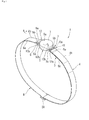
- Fig. 2 is a perspective view illustrating the heartbeat measurement device 1
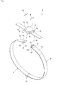
- Fig. 3 is an exploded perspective view illustrating the heartbeat measurement device 1.
- the heartbeat measurement device 1 is mounted to the chest which is a biological surface of the user U to detect an electro-cardiac signal generated in association with heartbeat, and wirelessly communicates the detected electro-cardiac signal.
- the heartbeat measurement device 1 includes a device main body 2, a heartbeat detection portion 3 formed integrally with the device main body 2, and a fixing band 4 for mounting the device main body 2 and the heartbeat detection portion 3 to the chest of the user U (see Fig. 1 ).
- the device main body 2 includes a case 7 of which the external shape is formed in a substantially disk shape, and a detection circuit board (not shown) provided within the case 7.
- the external shape of the case 7 is not limited to the substantial disk shape of the embodiment, but may be, for example, rectangular plate-shaped.
- a detection circuit board (not shown) includes a wireless transmission portion and a transmitter circuit (both not shown), and performs wireless communication on the basis of the signal detected by the heartbeat detection portion 3.
- the heartbeat detection portion 3 is electrically connected to the detection circuit board.
- the heartbeat detection portion 3 is constituted by a pair of electrodes 6a and 6b.
- the electrodes 6a and 6b are made of belt-like conductive elastomer, and one-side ends thereof in the long-side direction are connected with the device main body 2 so it is interposed therebetween.
- the electrodes 6a and 6b are electrically connected to the detection circuit board through an electrical connection portion 25 provided to the electrodes 6a and 6b and the detection circuit board (not shown) of the device main body 2.
- conductive elastomer for example, conductive silicon rubber mixed with carbon black, conductive rubber mixed with carbon black, conductive polyurethane rubber mixed with carbon black, or the like can be used.
- connection member 5 is constituted by a pair of arms 5a extended out from the outer circumferential surface of the case 7 toward the radial outside of the case 7 along the belt-like electrodes 6a and 6b, and a rod-shaped engaged portion 5b extending so as to be laid across a pair of arms 5a.
- the engaged portion 5b of the connection member 5 is formed detachably to a hook portion 12b of a strap attaching and detaching member 12 provided to an elastic strap 8 described later.
- the fixing band 4 is formed in a substantially ring shape so as to be mounted over the whole circumference of the chest of the user U (see Fig. 1 ).
- the fixing band 4 is the elastic strap 8 having elasticity which is formed in a belt shape, and the device main body 2 is connected thereto so as to be laid across both ends of the elastic strap 8 in the long-side direction.
- a length adjustment member 24 for adjusting the length of the elastic strap 8 is provided substantially at the center of the elastic strap 8 in the long-side direction.
- the strap attaching and detaching member 12 capable of attaching and detaching the elastic strap 8 and the device main body 2 is provided on both ends of the elastic strap 8 in the long-side direction.
- the strap attaching and detaching member 12 is constituted by an elliptically ring-shaped frame body 12a and the hook portion 12b curvedly formed from a region located along the long-side direction of the frame body 12a toward the radial outside of the frame body 12a. Meanwhile, the frame body 12a and the hook portion 12b may be formed integrally with each other, or may be bonded to each other after they are formed separately.
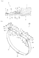
- Fig. 4 is a cross-sectional view taken along the line A-A of Fig. 2 .
- an elastic strap body 8b and the elastic strap end 8a are fixed and installed.
- the elastic strap body 8b and the elastic strap end 8a are fixed to each other by sewing, a hook-and-loop fastener or the like.
- the elastic strap 8 and the device main body 2 are detachably installed by engaging the hook portion 12b of the strap attaching and detaching member 12 with the engaged portion 5b of the connection member 5. That is, the hook portion 12b of the strap attaching and detaching member 12 and the engaged portion 5b of the connection member 5 constitute an engagement portion of the elastic strap 8 and the device main body 2. Thereby, it is possible to reliably prevent the device main body 2 from falling off the fixing band 4 at the time of mounting the heartbeat measurement device, and to easily perform attachment and detachment of the device main body 2 and the fixing band 4 to and from each other at time of maintenance.
- the hook portion 12b of the strap attaching and detaching member 12 is engaged with the engaged portion 5b of the connection member 5, it is preferable that an opening of the hook portion 12b is disposed on the opposite side to the electrode 6a. Thereby, the electrode 6a is prevented from being damaged due to the tip of the hook portion 12b, and the hook portion 12b is prevented from falling off when the heartbeat detection portion 3 is mounted.
- the heartbeat measurement device 1 is mounted to the chest of the user U (see Fig. 1 ) in the following procedure based on such a configuration.
- the hook portion 12b of one (for example, right side in Fig. 2 ) strap attaching and detaching member 12 out of the strap attaching and detaching member 12 provided on both ends of the fixing band 4, and the engaged portion 5b of one connection member 5 out of a pair of connection members 5 provided to the device main body 2 are engaged with each other.
- the electrodes 6a and 6b are brought into contact with the surface of the human body of the user U and the fixing band 4 is wound around the chest of the user U.
- the hook portion 12b of the other (for example, left side in Fig. 2 ) strap attaching and detaching member 12 and the engaged portion 5b of the other connection member 5 are engaged with each other.
- the fixing band 4 is installed on the chest of the user U.
- the length of the elastic strap 8 of the fixing band 4 is adjusted by the length adjustment member 24. Since the elastic strap 8 has elasticity, the length of the entire fixing band 4 is set to be slightly shorter than the chest circumference of the user U, so that the elastic strap 8 is elongated slightly, and adherence of the fixing band 4 and the electrodes 6a and 6b to the user U increases.
- the mounting of the heartbeat measurement device 1 to the user U is completed. That is, in a state where the fixing band 4 and the heartbeat detection portion 3 are separated from each other, the heartbeat detection portion 3 and the device main body 2 are fixed to the user U.
- An electro-cardiac signal generated in association with a heartbeat is detected by the pair of electrodes 6a and 6b.
- the detection circuit board (not shown) of the device main body 2 wirelessly communicates the electro-cardiac signal detected by the pair of electrodes 6a and 6b.
- the device main body 2 and the heartbeat detection portion 3 in a state where the fixing band 4 and the heartbeat detection portion 3 having the electrodes 6a and 6b are separated from each other, the device main body 2 and the heartbeat detection portion 3 can be fixed to the user U, and thus it is possible to prevent external force from being applied to the heartbeat detection portion 3 having the electrodes 6a and 6b.
- the device main body 2 and the heartbeat detection portion 3 can be separated from the fixing band 4 in a state where the device main body 2 and the heartbeat detection portion 3 are formed integrally with each other, it is possible to easily perform cleaning of only the fixing band 4.
- the fixing band 4 is not provided with the electrodes 6a and 6b, it is possible to reliably prevent defects from occurring in electrical parts such as the electrodes 6a and 6b and the electrical connection portion 25.
- the heartbeat measurement device 1 it is possible to perform cleaning of the simple fixing band 4 while securing good maintenance, and to reliably prevent defects from occurring in electrical parts such as the electrodes 6a and 6b and the electrical connection portion 25.
- both ends of the fixing band 4 in the long-side direction are connected to the device main body 2, it is possible to accurately perform positioning of the device main body 2 with respect to the fixing band 4, and to prevent displacement thereof. For this reason, it is possible to provide the heartbeat measurement device 1 having good installation stability.
- the fixing band 4 and the device main body 2 are detachably installed by the engagement portion constituted by the hook portion 12b of the strap attaching and detaching member 12 provided to the fixing band 4 and the engaged portion 5b of the connection member 5 provided to the device main body 2. Therefore, it is possible to reliably prevent the device main body 2 from falling off the fixing band 4 at the time of mounting the heartbeat measurement device 1, and to easily perform attachment and detachment of the device main body 2 and the fixing band 4 to and from each other at the time of maintenance.
- the electrodes 6a and 6b are formed from conductive elastomer and thus are soft, and are pressed to the fixing band 4. Thereby, the electrodes are elastically deformed along the chest of the user U. For this reason, the electrodes 6a and 6b reliably adhere tightly to the chest of the user U. Therefore, it is possible to detect an electro-cardiac signal with a higher degree of accuracy.
- Fig. 5 is a perspective view illustrating a heartbeat measurement device 201 according to a second embodiment
- Fig. 6 is an exploded perspective view illustrating the heartbeat measurement device 201 according to the second embodiment.
- the heartbeat measurement device 201 according to the second embodiment will be described with reference to Figs. 5 and 6 .
- the heartbeat measurement device 1 is configured such that the fixing band 4 is formed by the elastic strap 8, and the elastic strap 8 and the device main body 2 are formed detachably.
- the heartbeat measurement device 201 according to the second embodiment is different from the heartbeat measurement device 1 according to the first embodiment, in that the fixing band 4 is formed by the elastic strap 8 and belts 9 and 10, and the belts 9 and 10 and the device main body 2 are formed detachably.
- the fixing band 4 includes the elastic strap 8, formed in a belt shape, which has elasticity and a pair of non-elastic belts 9 and 10, formed in a belt shape, which are connected to both ends of the elastic strap 8 in the long-side direction.
- the pair of belts 9 and 10 are formed in a substantially belt shape by a fiber material, and are disposed so as to cover the electrodes 6a and 6b of the heartbeat detection portion 3 from the outside with the device main body 2 interposed therebetween. Meanwhile, the belt 9 disposed at the electrode 6a side and the belt 10 disposed at the electrode 6b side are the same as each other in shape. Therefore, hereinafter, description of the belt 9 disposed at the electrode 6a side will be made, while description of the belt 10 disposed at the electrode 6b side will be omitted.
- a ring portion 9d formed by folding back an end 9b of the belt 9 is provided at the elastic strap 8 side in the long-side direction of the belt 9.
- the ring portion 9d is provided with a strap connector 19 capable of being connected to the elastic strap 8.
- the strap connector 19 is constituted by a shaft 21 inserted into the ring portion 9d and a connector body 22 provided so as to be laid across both ends of the shaft 21.
- the tip of the shaft 21 is configured to freely come in and out, and to be in a state where it is biased toward the tip side by a spring (not shown).
- the connector body 22 is formed in an approximately lateral U-shape when seen in a plan view, and is a component in which a shaft portion 22a and a pair of arm portions 22b and 22b curvedly extended from both ends of the shaft portion 22a toward the shaft 21 are formed integrally with each other.
- the strap connector 19 is formed in a rectangular frame shape by disposing the shaft 21 between the pair of arm portions 22b and 22b, and is installed at the elastic strap 8 side in the long-side direction of the belt 9.
- Fig. 7 is a cross-sectional view taken along the line B-B of Fig. 5 .
- a hook-and-loop fastener 33 is provided to the belt body 9c and the belt end 9a.
- the belt body 9c and the belt end 9a are detachably installed, and the belt 9 and the device main body 2 are detachably installed.
- the hook-and-loop fastener 33 provided to the belt body 9c and the belt end 9a constitutes an engagement portion between the belt 9 and the device main body 2.
- a pair of belts 9 and 10 are respectively connected to both ends of the elastic strap 8.
- the strap attaching and detaching member 12 is provided at the electrode 6a side of the elastic strap 8, and the hook portion 12b of the strap attaching and detaching member 12 and the shaft portion 22a of the strap connector 19 are engageable with each other. Thereby, the electrode 6a side of the elastic strap 8 and the belt 9 are detachably installed.
- the electrode 6b side of the elastic strap 8 after the elastic strap end 8a is inserted into the strap connector 19, the strap end is folded back to the side opposite to the belt 9 and the elastic strap end 8a is fixed to the elastic strap body 8b. Thereby, the electrode 6b side of the elastic strap 8 and the belt 9 are connected to each other.
- belt-like human body protective portions 23a and 23b for preventing the strap attaching and detaching member 12 and the strap connector 19 from being exposed to the inner surface side, that is, preventing from being exposed to the side of the chest of the user U (see Fig. 1 ), are installed on the ring portions 9d and 10d of the belts 9 and 10. Thereby, there is no case where the strap attaching and detaching member 12 and the strap connector 19 come into direct contact with the chest of the user U, and thus the user U feels no sense of discomfort.
- the heartbeat measurement device 1 since it is possible to perform cleaning of the simple fixing band 4 while securing good maintenance similarly to the first embodiment, it is possible to reliably prevent defects from occurring to electrical parts such as the electrodes 6a and 6b and the electrical connection portion 25. Further, the heartbeat detection portion 3 is prevented from being exposed by covering the heartbeat detection portion 3 using the belts 9 and 10, and thus it is possible to prevent the electrodes 6a and 6b of the heartbeat detection portion 3 from being short-circuited to each other through clothes or the like, and to improve designability. In addition, since the belts 9 and 10 are non-elastic, it is possible to more accurately perform positioning of the device main body 2 with respect to the fixing band 4.
- Fig. 8 is a perspective view illustrating the periphery of electrodes 216a and 216b according to a first modified example of the second embodiment.
- Fig. 9 is a top view illustrating the periphery of the electrodes 216a and 216b according to the first modified example of the second embodiment.
- a heartbeat measurement device 211 according to the first modified example of the second embodiment will be described with reference to Figs. 8 and 9 .
- a pair of belts 9 and 10 are disposed so as to cover the electrodes 6a and 6b of the heartbeat detection portion 3 from the outside.
- the heartbeat measurement device 211 according to the first modified example of the second embodiment is different from that in the above-mentioned embodiment, in that the pair of belts 9 and 10 are disposed so as to cover the electrodes 216a and 216b of the heartbeat detection portion 310 from the outside, and a guide portion 41 is further formed in the electrodes 216a and 216b. Meanwhile, detailed description of the same configuration as that of the second embodiment will be omitted.
- Figs. 8 and 9 the guide portion 41 on the belt 10 side is shown and the guide portion 41 on the belt 9 side is not shown, but the guide portion 41 on the belt 10 side and the guide portion 41 on the belt 9 side have the same structure as each other.
- description of the guide portion 41 on the belt 10 side will be made, while description of the guide portion 41 on the belt 9 side will be omitted.
- the guide portion 41 is formed on the end on the opposite side (right side in Figs. 8 and 9 ) to the device main body 2.
- the guide portion 41 is constituted by two walls 41 a and 41 b formed upright from both sides of the electrode 216b in the short-side direction toward the belt 10 side.
- a receiving concave portion 43 capable of receiving the belt 10 is formed by the two walls 41 a and 41 b and the electrode 216b.
- the belt 10 is received in the receiving concave portion 43 of the electrode 216b. Then, displacement of the electrode 216b in the width direction with respect to the belt 10 is regulated by the walls 41 a and 41 b of the receiving concave portion 43. For this reason, displacement of the relative positions of the belt 10 and the electrode 216b is prevented from occurring. That is, the receiving concave portion 43 constitutes a displacement regulation portion that regulates displacement of the relative positions of the belt 10 and the heartbeat detection portion 310.
- an insulation processing method is not limited to insulating coating.
- the electrodes 216a and 216b can be caused to reliably adhere tightly to the chest of the user U, and thus it is possible to improve measurement accuracy of the heartbeat measurement device 211.
- displacement between the belts 9 and 10 and the heartbeat detection portion 310 can be prevented from occurring, and thus it is possible to reliably prevent the electrodes 216a and 216b of the heartbeat detection portion 310 from being short-circuited through clothes or the like due to exposure of the heartbeat detection portion 310 from the belt.
- Fig. 10 is a perspective view illustrating the periphery of electrodes 226a and 226b according to a second modified example of the second embodiment.
- Fig. 11 is a top view illustrating the periphery of the electrodes 226a and 226b according to the second modified example of the second embodiment.
- a heartbeat measurement device 221 according to the second modified example of the second embodiment will be described with reference to Figs. 10 and 11 .
- a pair of belts 9 and 10 are disposed so as to cover the electrodes 6a and 6b of the heartbeat detection portion 3 from the outside.
- the heartbeat measurement device 221 according to the second modified example of the second embodiment is different from that in the above-mentioned embodiment, in that a pair of belts 209 and 210 are disposed so as to cover the electrodes 226a and 226b of a heartbeat detection portion 320 from the outside, and a displacement prevention portion 53 is further formed in a pair of belts 209 and 210 and the electrodes 226a and 226b. Meanwhile, detailed description of the same configuration as that of the second embodiment will be omitted.
- a convex portion 51 protrudes toward the belt 210 side, at the end on the opposite side (right side in Figs. 8 and 9 ) to the device main body 2.
- a long hole portion 52 into which the convex portion 51 can be inserted is formed at a place corresponding to the convex portion 51.
- the long hole portion 52 is formed in an elliptical shape along the long-side direction of the belt 210.
- the convex portion 51 of the electrode 226b is inserted into the long hole portion 52 of the belt 210.
- displacement of the electrode 226b in the width direction with respect to the belt 210 is regulated, that is, displacement of the relative positions of the belt 210 and the electrode 226b is prevented from occurring.
- the displacement prevention portion 53 constitutes a displacement regulation portion that regulates displacement of the relative positions of the belt 210 and the heartbeat detection portion 320.
- the convex portion 51 of the electrodes 226a and 226b is exposed to the outside through the long hole portion 52 of the belts 209 and 210, in a state where the device main body 2 and the electrodes 226a and 226b are installed on the fixing band 204. For this reason, in order to prevent a pair of electrodes 226a and 226b from being short-circuited through clothes or the like, it is preferable to perform an insulation process such as application of an insulating coating to the convex portion 51.
- an insulation processing method is not limited to insulating coating.
- the convex portion 51 may be formed by a separate member from the electrodes 226a and 226b, that is, an insulating member, and may be installed on the electrodes 226a and 226b.
- the electrodes 226a and 226b and the convex portion 51 can also be formed by two-color molding.
- the engagement portion between the elastic strap 8 (fixing band 4) and the device main body 2 is constituted by the hook portion 12b of the strap attaching and detaching member 12 and the engaged portion 5b of the connection member 5.
- the engagement portion between the belts 9 and 10 (fixing band 4) and the device main body 2 is constituted by the hook-and-loop fastener 33 provided to the belt bodies 9c and 10c and the belt ends 9a and 10a.
- the engagement portion provided between the fixing band 4 and the device main body 2 is not limited to the above-mentioned embodiment.
- Fig. 12 is an explanatory diagram illustrating another engagement portion.
- a dovetail groove-shaped slot 5c is formed along the width direction (paper front-and-back direction in Fig. 12 ) of the fixing band 4, in the connection member 5 of the device main body 2.
- a rail 12c corresponding to the shape of the slot 5c is formed in the strap attaching and detaching member 12.
- the rail 12c is inserted into and extracted from the dovetail groove-shaped slot 5c from the width direction of the fixing band 4, so that the fixing band 4 and the device main body 2 are detachably installed.
- the engagement portion between the fixing band 4 and the device main body 2 may be constituted by the slot 5c formed in the connection member 5 of the device main body 2 and the rail 12c formed in the strap attaching and detaching member 12.
- the engagement portion between the fixing bands 4 and 204 and the device main body 2 is not limited to the above-mentioned embodiment, but various engagement portions can be adopted.
- the electrodes 216a and 216b are provided with the guide portion 41.
- the guide portion 41 may be applied to the first embodiment. Thereby, it is possible to regulate displacement of the elastic strap 8.
- the displacement regulation portion that prevents displacement of the relative positions of the belts 9 and 10 and the electrodes 216a and 216b by providing the electrodes 216a and 216b with the guide portion 41 has been described.
- the displacement regulation portion that prevents displacement of the relative positions of the belts 209 and 210 and the electrodes 226a and 226b from occurring by protrusively forming the convex portion 51 in the electrodes 226a and 226b and forming the long hole portion 52, capable of having the convex portion 51 inserted therein, in the belts 209 and 210 has been described.
- the displacement regulation portion is not limited thereto, but may be a structure capable of preventing displacement of the relative positions of the belts 9 and 10 and the electrodes 216a and 216b, or displacement of the relative positions of the belts 209 and 210 and the electrodes 226a and 226b.
- displacement of each relative position may be prevented from occurring by providing a hook-and-loop fastener to the belts 9 and 10 and the electrodes 6a and 6b in the second embodiment.
- the device main body 2 and the heartbeat detection portions 3, 310, and 320 are integrally formed in the heartbeat measurement devices 1, 201, 211, and 221 that measure the heart rate of the user U as a biological information detection device, and the device main body 2 and the heartbeat detection portion 3 are installed on the chest of the user U using the fixing bands 4 and 204.
- a configuration is not only applied to the heartbeat measurement devices 1, 201, 211, and 221, but is also capable of being applied to various biological information detection devices.
- the configurations of the above-mentioned embodiments can be applied to devices that measure blood pressure, body temperature, myogenic potential and the like.
- a material having elasticity is adopted for the elastic strap 8, and a non-elastic material is adopted for the belts 9, 10, 209, and 210.
- a material having a moisture retaining property may be further adopted for the elastic strap 8 and the belts 9, 10, 209, and 210.
- a material containing polyester, nylon or the like as a main ingredient may be adopted for the elastic strap 8 and the belts 9, 10, 209, and 210.
- a moisture absorbing material such as PVA sponge may be provided to the inner surface side of the elastic strap 8 or the belts 9, 10, 209, and 210.
Landscapes
- Health & Medical Sciences (AREA)
- Life Sciences & Earth Sciences (AREA)
- Medical Informatics (AREA)
- Biophysics (AREA)
- Pathology (AREA)
- Engineering & Computer Science (AREA)
- Biomedical Technology (AREA)
- Heart & Thoracic Surgery (AREA)
- Physics & Mathematics (AREA)
- Molecular Biology (AREA)
- Surgery (AREA)
- Animal Behavior & Ethology (AREA)
- General Health & Medical Sciences (AREA)
- Public Health (AREA)
- Veterinary Medicine (AREA)
- Cardiology (AREA)
- Physiology (AREA)
- Measurement And Recording Of Electrical Phenomena And Electrical Characteristics Of The Living Body (AREA)
- Measuring Pulse, Heart Rate, Blood Pressure Or Blood Flow (AREA)
Abstract
Description
- The present invention relates to a biological information detection device that detects a biological signal by installing an electrode on the biological surface of the human body.
- Among these kinds of biological information detection devices, there is, for example, a device that detects an electro-cardiac signal generated in association with a heartbeat, and measures a heart rate from the biological surface. As such a biological information detection device, there is, for example, a device which includes a main body portion having a detection circuit board and the like built-in, and a strap for mounting the main body portion to the human body, the strap being provided with a pair of electrodes. The main body portion and the strap are provided with an electrical connection portion for electrically connecting a detection circuit board of the main body portion to an electrode of the strap.
- Based on such a configuration, an electro-cardiac signal generated in association with a heartbeat is detected by bringing a pair of electrodes into contact with the chest (biological surface) of the human body, and the main body portion derives a heart rate on the basis of the detected electro-cardiac signal.
- Further, among the biological information detection devices, there is, for example, a device in which the main body portion is detachably provided to the strap from the viewpoint of maintenance, such as cleaning of the strap. When the main body portion is mounted to the strap, the electrical connection portion provided to the strap and the electrical connection portion provided to the main body portion are mechanically connected to each other, and the detection circuit board and the electrode are electrically connected to each other (see, for example, Specification of
U.S. Patent No. 7526840 ). - However, in the above-mentioned related art, since the main body portion and the electrode are formed to be detachable from each other, there is a problem that the detection performance of the heartbeat measurement device becomes unstable depending on the installation conditions of the electrical connection portion. In addition, there is concern of the electrical connection portion being damaged by repeatedly performing attaching and detaching operations of the main body portion and the electrode.
- Further, since the strap is provided with an electrode, external force in the tensile direction is applied to the electrode and the electrical connection portion at all times, in a state where the heartbeat measurement device is installed on the human body. For this reason, there is concern of the electrical connection portion provided to the strap and the electrical connection portion provided to the main body portion being mechanically separated from each other, and thus the electrical connection between the detection circuit board and the electrode being cut off. In addition to this, there is concern of the electrode portion being exposed to a cleaning solution in association with cleaning of the strap at the time of maintenance, and thus electrical parts such as the electrode and the electrical connection portion being damaged.
- Consequently, the present invention is contrived in view of such circumstances, and an object thereof is to provide a biological information detection device capable of preventing defects from occurring in electrical parts such as the electrode and the electrical connection portion while securing good maintenance, and preventing the detection performance from becoming unstable.
- According to an aspect of the present invention, there is provided a biological information detection device including: a device main body; a biological signal detection portion, formed integrally with the device main body, which has an electrode that comes into contact with a biological surface; and a fixing portion, formed in a belt shape, which fixes the device main body and the biological signal detection portion to a human body, wherein both ends of the fixing portion in a long-side direction are detachably installed on the device main body through an engagement portion.
- According to the aspect of the present invention, since the device main body and the biological signal detection portion can be fixed to the human body in a state where the fixing portion and the biological signal detection portion including the electrode are separated from each other, it is possible to prevent external force from being applied to the biological signal detection portion. In addition, the device main body and the biological signal detection portion can be separated from the fixing portion in a state where the device main body and the biological signal detection portion are formed integrally with each other. For this reason, it is possible to perform cleaning of a simple fixing portion while securing good maintenance, and to reliably prevent defects from occurring in electrical parts such as the electrode and the electrical connection portion.
- Further, since both ends of the fixing portion in the long-side direction are connected to the device main body, it is possible to accurately perform positioning of the device main body with respect to the fixing portion, and to prevent displacement thereof. For this reason, it is possible to provide the biological information detection device having good installation stability.
- In addition, the fixing portion may include at least an elastic strap, and a non-elastic belt connected to at least one of one end and the other end of the strap in a long-side direction. The belt may be formed so as to cover the biological signal detection portion, and may be detachably installed on the device main body through the engagement portion.
- According to the aspect of the present invention, the biological signal detection portion is prevented from being exposed by covering the biological signal detection portion using the belt, and thus it is possible to prevent the electrode of the biological signal detection portion from being short-circuited through clothes or the like, and to improve designability. In addition, since the belt is non-elastic, it is possible to more accurately perform positioning of the device main body with respect to the fixing portion.
- In addition, a displacement regulation portion that regulates displacement of a relative position may be provided between the belt and the biological signal detection portion.
- According to the aspect of the present invention, the electrode is able to be caused to reliably adhere tightly to the chest of the user, and thus it is possible to improve detection accuracy of the biological information detection device. In addition, displacement between the belt and the biological signal detection portion is able to be prevented from occurring, and thus it is possible to reliably prevent the electrode of the biological signal detection portion from being short-circuited through clothes or the like due to exposure of the biological signal detection portion from the belt.
- In addition, the engagement portion may be constituted by a hook portion provided to one of the device main body and the fixing portion, and an engaged portion, provided to the other one of the device main body and the fixing portion, which is engaged with the hook portion.
- According to the aspect of the present invention, it is possible to reliably prevent the device main body from falling off the fixing portion at the time of mounting the biological information detection device, and to easily perform attachment and detachment of the device main body and the fixing portion to and from each other at the time of maintenance.
- In addition, the biological signal detection portion may be formed from conductive elastomer, and the conductive elastomer serve as the electrode.
- According to the aspect of the present invention, it is possible to easily elastically deform the biological signal detection portion, and to increase adhesion of the electrode to the biological surface. For this reason, it is possible to detect the biological signal with a higher degree of accuracy.
- According to the present invention, since the device main body and the biological signal detection portion can be fixed to the human body in a state where the fixing portion and the biological signal detection portion including the electrode are separated from each other, it is possible to prevent external force from being applied to the biological signal detection portion. In addition, the device main body and the biological signal detection portion can be separated from the fixing portion in a state where the device main body and the biological signal detection portion are formed integrally with each other. For this reason, it is possible to perform cleaning of the simple fixing portion while securing good maintenance, and to reliably prevent defects from occurring in electrical parts such as the electrode and the electrical connection portion.
- Further, since both ends of the fixing portion in the long-side direction are connected to the device main body, it is possible to accurately perform positioning of the device main body with respect to the fixing portion, and to prevent displacement thereof. For this reason, it is possible to provide the biological information detection device having good installation stability.
- Embodiments of the present invention will now be described by way of further example only and with reference to the accompanying drawings, in which:
-
Fig. 1 is an explanatory diagram illustrating a state where a heartbeat measurement device according to a first embodiment of the present invention is installed on a user. -
Fig. 2 is a perspective view illustrating the heartbeat measurement device according to the first embodiment. -
Fig. 3 is an exploded perspective view illustrating the heartbeat measurement device according to the first embodiment. -
Fig. 4 is a cross-sectional view taken along the line A-A ofFig. 2 . -
Fig. 5 is a perspective view illustrating a heartbeat measurement device according to a second embodiment. -
Fig. 6 is an exploded perspective view illustrating the heartbeat measurement device according to the second embodiment. -
Fig. 7 is a cross-sectional view taken along the line B-B ofFig. 5 . -
Fig. 8 is a perspective view illustrating the periphery of an electrode according to a first modified example of the second embodiment. -
Fig. 9 is a top view illustrating the periphery of the electrode according to the first modified example of the second embodiment. -
Fig. 10 is a perspective view illustrating the periphery of an electrode according to a second modified example of the second embodiment. -
Fig. 11 is a top view illustrating the periphery of the electrode according to the second modified example of the second embodiment. -
Fig. 12 is an explanatory diagram illustrating another engagement portion. - Next, a first embodiment of the present invention will be described with reference to the drawings.
-
Fig. 1 is an explanatory diagram illustrating a state where aheartbeat measurement device 1 which is a biological information detection device according to the present invention is installed on a user U,Fig. 2 is a perspective view illustrating theheartbeat measurement device 1, andFig. 3 is an exploded perspective view illustrating theheartbeat measurement device 1. - As shown in
Fig. 1 , theheartbeat measurement device 1 is mounted to the chest which is a biological surface of the user U to detect an electro-cardiac signal generated in association with heartbeat, and wirelessly communicates the detected electro-cardiac signal. As shown inFig. 2 , theheartbeat measurement device 1 includes a devicemain body 2, aheartbeat detection portion 3 formed integrally with the devicemain body 2, and afixing band 4 for mounting the devicemain body 2 and theheartbeat detection portion 3 to the chest of the user U (seeFig. 1 ). - The device
main body 2 includes acase 7 of which the external shape is formed in a substantially disk shape, and a detection circuit board (not shown) provided within thecase 7. Meanwhile, the external shape of thecase 7 is not limited to the substantial disk shape of the embodiment, but may be, for example, rectangular plate-shaped. - A detection circuit board (not shown) includes a wireless transmission portion and a transmitter circuit (both not shown), and performs wireless communication on the basis of the signal detected by the
heartbeat detection portion 3. Theheartbeat detection portion 3 is electrically connected to the detection circuit board. - As shown in
Fig. 3 , theheartbeat detection portion 3 is constituted by a pair ofelectrodes electrodes main body 2 so it is interposed therebetween. Theelectrodes electrical connection portion 25 provided to theelectrodes main body 2. - Meanwhile, as the conductive elastomer, for example, conductive silicon rubber mixed with carbon black, conductive rubber mixed with carbon black, conductive polyurethane rubber mixed with carbon black, or the like can be used.
- In the
case 7, a pair ofconnection members 5 are provided at positions corresponding to the pair ofelectrodes connection member 5 is constituted by a pair ofarms 5a extended out from the outer circumferential surface of thecase 7 toward the radial outside of thecase 7 along the belt-like electrodes portion 5b extending so as to be laid across a pair ofarms 5a. The engagedportion 5b of theconnection member 5 is formed detachably to ahook portion 12b of a strap attaching and detachingmember 12 provided to anelastic strap 8 described later. - The fixing
band 4 is formed in a substantially ring shape so as to be mounted over the whole circumference of the chest of the user U (seeFig. 1 ). Specifically, the fixingband 4 is theelastic strap 8 having elasticity which is formed in a belt shape, and the devicemain body 2 is connected thereto so as to be laid across both ends of theelastic strap 8 in the long-side direction. - A
length adjustment member 24 for adjusting the length of theelastic strap 8 is provided substantially at the center of theelastic strap 8 in the long-side direction. - The strap attaching and detaching
member 12 capable of attaching and detaching theelastic strap 8 and the devicemain body 2 is provided on both ends of theelastic strap 8 in the long-side direction. The strap attaching and detachingmember 12 is constituted by an elliptically ring-shapedframe body 12a and thehook portion 12b curvedly formed from a region located along the long-side direction of theframe body 12a toward the radial outside of theframe body 12a. Meanwhile, theframe body 12a and thehook portion 12b may be formed integrally with each other, or may be bonded to each other after they are formed separately. -
Fig. 4 is a cross-sectional view taken along the line A-A ofFig. 2 . - As shown in
Fig. 4 , in the strap attaching and detachingmember 12 and theelastic strap 8, after anelastic strap end 8a is inserted into theframe body 12a, the strap end is folded back to the side opposite to thehook portion 12b, and anelastic strap body 8b and theelastic strap end 8a are fixed and installed. Theelastic strap body 8b and theelastic strap end 8a are fixed to each other by sewing, a hook-and-loop fastener or the like. - The
elastic strap 8 and the devicemain body 2 are detachably installed by engaging thehook portion 12b of the strap attaching and detachingmember 12 with the engagedportion 5b of theconnection member 5. That is, thehook portion 12b of the strap attaching and detachingmember 12 and the engagedportion 5b of theconnection member 5 constitute an engagement portion of theelastic strap 8 and the devicemain body 2. Thereby, it is possible to reliably prevent the devicemain body 2 from falling off the fixingband 4 at the time of mounting the heartbeat measurement device, and to easily perform attachment and detachment of the devicemain body 2 and the fixingband 4 to and from each other at time of maintenance. - Herein, when the
hook portion 12b of the strap attaching and detachingmember 12 is engaged with the engagedportion 5b of theconnection member 5, it is preferable that an opening of thehook portion 12b is disposed on the opposite side to theelectrode 6a. Thereby, theelectrode 6a is prevented from being damaged due to the tip of thehook portion 12b, and thehook portion 12b is prevented from falling off when theheartbeat detection portion 3 is mounted. - The
heartbeat measurement device 1 is mounted to the chest of the user U (seeFig. 1 ) in the following procedure based on such a configuration. - As shown in
Fig. 2 , thehook portion 12b of one (for example, right side inFig. 2 ) strap attaching and detachingmember 12 out of the strap attaching and detachingmember 12 provided on both ends of the fixingband 4, and the engagedportion 5b of oneconnection member 5 out of a pair ofconnection members 5 provided to the devicemain body 2 are engaged with each other. - Subsequently, while the device
main body 2 is disposed at the center of the chest of the user U in a state where onehook portion 12b and one engagedportion 5b are engaged with each other, theelectrodes band 4 is wound around the chest of the user U. Thehook portion 12b of the other (for example, left side inFig. 2 ) strap attaching and detachingmember 12 and the engagedportion 5b of theother connection member 5 are engaged with each other. Thereby, the fixingband 4 is installed on the chest of the user U. - Finally, the length of the
elastic strap 8 of the fixingband 4 is adjusted by thelength adjustment member 24. Since theelastic strap 8 has elasticity, the length of theentire fixing band 4 is set to be slightly shorter than the chest circumference of the user U, so that theelastic strap 8 is elongated slightly, and adherence of the fixingband 4 and theelectrodes - As stated above, the mounting of the
heartbeat measurement device 1 to the user U is completed. That is, in a state where the fixingband 4 and theheartbeat detection portion 3 are separated from each other, theheartbeat detection portion 3 and the devicemain body 2 are fixed to the user U. An electro-cardiac signal generated in association with a heartbeat is detected by the pair ofelectrodes main body 2 wirelessly communicates the electro-cardiac signal detected by the pair ofelectrodes - According to the first embodiment, in a state where the fixing
band 4 and theheartbeat detection portion 3 having theelectrodes main body 2 and theheartbeat detection portion 3 can be fixed to the user U, and thus it is possible to prevent external force from being applied to theheartbeat detection portion 3 having theelectrodes main body 2 and theheartbeat detection portion 3 can be separated from the fixingband 4 in a state where the devicemain body 2 and theheartbeat detection portion 3 are formed integrally with each other, it is possible to easily perform cleaning of only the fixingband 4. At this time, since the fixingband 4 is not provided with theelectrodes electrodes electrical connection portion 25. In this manner, in theheartbeat measurement device 1, it is possible to perform cleaning of thesimple fixing band 4 while securing good maintenance, and to reliably prevent defects from occurring in electrical parts such as theelectrodes electrical connection portion 25. - Further, since both ends of the fixing
band 4 in the long-side direction are connected to the devicemain body 2, it is possible to accurately perform positioning of the devicemain body 2 with respect to the fixingband 4, and to prevent displacement thereof. For this reason, it is possible to provide theheartbeat measurement device 1 having good installation stability. - In addition, the fixing
band 4 and the devicemain body 2 are detachably installed by the engagement portion constituted by thehook portion 12b of the strap attaching and detachingmember 12 provided to the fixingband 4 and the engagedportion 5b of theconnection member 5 provided to the devicemain body 2. Therefore, it is possible to reliably prevent the devicemain body 2 from falling off the fixingband 4 at the time of mounting theheartbeat measurement device 1, and to easily perform attachment and detachment of the devicemain body 2 and the fixingband 4 to and from each other at the time of maintenance. - In addition, the
electrodes band 4. Thereby, the electrodes are elastically deformed along the chest of the user U. For this reason, theelectrodes -
Fig. 5 is a perspective view illustrating aheartbeat measurement device 201 according to a second embodiment, andFig. 6 is an exploded perspective view illustrating theheartbeat measurement device 201 according to the second embodiment. - Subsequently, the
heartbeat measurement device 201 according to the second embodiment will be described with reference toFigs. 5 and6 . - The
heartbeat measurement device 1 according to the first embodiment is configured such that the fixingband 4 is formed by theelastic strap 8, and theelastic strap 8 and the devicemain body 2 are formed detachably. - On the other hand, the
heartbeat measurement device 201 according to the second embodiment is different from theheartbeat measurement device 1 according to the first embodiment, in that the fixingband 4 is formed by theelastic strap 8 andbelts belts main body 2 are formed detachably. - Meanwhile, detailed description of the same configurations as those of the first embodiment such as the configuration in which the
heartbeat detection portion 3 and the fixingband 4 are separated from each other will be omitted. - As shown in
Fig. 5 , the fixingband 4 includes theelastic strap 8, formed in a belt shape, which has elasticity and a pair ofnon-elastic belts elastic strap 8 in the long-side direction. - The pair of
belts electrodes heartbeat detection portion 3 from the outside with the devicemain body 2 interposed therebetween. Meanwhile, thebelt 9 disposed at theelectrode 6a side and thebelt 10 disposed at theelectrode 6b side are the same as each other in shape. Therefore, hereinafter, description of thebelt 9 disposed at theelectrode 6a side will be made, while description of thebelt 10 disposed at theelectrode 6b side will be omitted. - As shown in
Fig. 6 , aring portion 9d formed by folding back anend 9b of thebelt 9 is provided at theelastic strap 8 side in the long-side direction of thebelt 9. Thering portion 9d is provided with astrap connector 19 capable of being connected to theelastic strap 8. Thestrap connector 19 is constituted by ashaft 21 inserted into thering portion 9d and aconnector body 22 provided so as to be laid across both ends of theshaft 21. - The tip of the
shaft 21 is configured to freely come in and out, and to be in a state where it is biased toward the tip side by a spring (not shown). - The
connector body 22 is formed in an approximately lateral U-shape when seen in a plan view, and is a component in which ashaft portion 22a and a pair ofarm portions shaft portion 22a toward theshaft 21 are formed integrally with each other. - The
strap connector 19 is formed in a rectangular frame shape by disposing theshaft 21 between the pair ofarm portions elastic strap 8 side in the long-side direction of thebelt 9. -
Fig. 7 is a cross-sectional view taken along the line B-B ofFig. 5 . - As shown in
Fig. 7 , at the devicemain body 2 side in the long-side direction of thebelt 9, after abelt end 9a is inserted between the devicemain body 2 and the engagedportion 5b of theconnection member 5, the belt end is folded back to the side opposite to the devicemain body 2, and abelt body 9c and thebelt end 9a are fixed and installed onto the devicemain body 2. - Herein, between the
belt body 9c and thebelt end 9a, a hook-and-loop fastener 33 is provided to thebelt body 9c and thebelt end 9a. Thereby, thebelt body 9c and thebelt end 9a are detachably installed, and thebelt 9 and the devicemain body 2 are detachably installed. That is, the hook-and-loop fastener 33 provided to thebelt body 9c and thebelt end 9a constitutes an engagement portion between thebelt 9 and the devicemain body 2. Thereby, it is possible to reliably prevent the devicemain body 2 from falling off thebelt 9 at the time of mounting theheartbeat measurement device 201, and to easily perform attachment and detachment of the devicemain body 2 and thebelt 9 to and from each other at the time of maintenance. - As shown in
Fig. 5 , a pair ofbelts elastic strap 8. The strap attaching and detachingmember 12 is provided at theelectrode 6a side of theelastic strap 8, and thehook portion 12b of the strap attaching and detachingmember 12 and theshaft portion 22a of thestrap connector 19 are engageable with each other. Thereby, theelectrode 6a side of theelastic strap 8 and thebelt 9 are detachably installed. - In addition, at the
electrode 6b side of theelastic strap 8, after theelastic strap end 8a is inserted into thestrap connector 19, the strap end is folded back to the side opposite to thebelt 9 and theelastic strap end 8a is fixed to theelastic strap body 8b. Thereby, theelectrode 6b side of theelastic strap 8 and thebelt 9 are connected to each other. - Meanwhile, belt-like human body
protective portions member 12 and thestrap connector 19 from being exposed to the inner surface side, that is, preventing from being exposed to the side of the chest of the user U (seeFig. 1 ), are installed on thering portions belts member 12 and thestrap connector 19 come into direct contact with the chest of the user U, and thus the user U feels no sense of discomfort. - According to the second embodiment, in the
heartbeat measurement device 1, since it is possible to perform cleaning of thesimple fixing band 4 while securing good maintenance similarly to the first embodiment, it is possible to reliably prevent defects from occurring to electrical parts such as theelectrodes electrical connection portion 25. Further, theheartbeat detection portion 3 is prevented from being exposed by covering theheartbeat detection portion 3 using thebelts electrodes heartbeat detection portion 3 from being short-circuited to each other through clothes or the like, and to improve designability. In addition, since thebelts main body 2 with respect to the fixingband 4. -
Fig. 8 is a perspective view illustrating the periphery ofelectrodes -
Fig. 9 is a top view illustrating the periphery of theelectrodes - A
heartbeat measurement device 211 according to the first modified example of the second embodiment will be described with reference toFigs. 8 and9 . - In the
heartbeat measurement device 201 according to the second embodiment, a pair ofbelts electrodes heartbeat detection portion 3 from the outside. On the other hand, theheartbeat measurement device 211 according to the first modified example of the second embodiment is different from that in the above-mentioned embodiment, in that the pair ofbelts electrodes heartbeat detection portion 310 from the outside, and aguide portion 41 is further formed in theelectrodes - In addition, in
Figs. 8 and9 , theguide portion 41 on thebelt 10 side is shown and theguide portion 41 on thebelt 9 side is not shown, but theguide portion 41 on thebelt 10 side and theguide portion 41 on thebelt 9 side have the same structure as each other. Hereinafter, description of theguide portion 41 on thebelt 10 side will be made, while description of theguide portion 41 on thebelt 9 side will be omitted. - In the
electrode 216b, theguide portion 41 is formed on the end on the opposite side (right side inFigs. 8 and9 ) to the devicemain body 2. Theguide portion 41 is constituted by twowalls electrode 216b in the short-side direction toward thebelt 10 side. A receivingconcave portion 43 capable of receiving thebelt 10 is formed by the twowalls electrode 216b. - When the device
main body 2 and theelectrode 216b are installed on the fixingband 4 based on such a configuration, thebelt 10 is received in the receivingconcave portion 43 of theelectrode 216b. Then, displacement of theelectrode 216b in the width direction with respect to thebelt 10 is regulated by thewalls concave portion 43. For this reason, displacement of the relative positions of thebelt 10 and theelectrode 216b is prevented from occurring. That is, the receivingconcave portion 43 constitutes a displacement regulation portion that regulates displacement of the relative positions of thebelt 10 and theheartbeat detection portion 310. - Meanwhile, two
walls belts main body 2 and theelectrodes band 4. For this reason, in order to prevent a pair ofelectrodes walls - Therefore, according to the first modified example of the second embodiment, in addition to the same effects as those of the first embodiment and the second embodiment, the
electrodes heartbeat measurement device 211. In addition, displacement between thebelts heartbeat detection portion 310 can be prevented from occurring, and thus it is possible to reliably prevent theelectrodes heartbeat detection portion 310 from being short-circuited through clothes or the like due to exposure of theheartbeat detection portion 310 from the belt. -
Fig. 10 is a perspective view illustrating the periphery ofelectrodes -
Fig. 11 is a top view illustrating the periphery of theelectrodes - A
heartbeat measurement device 221 according to the second modified example of the second embodiment will be described with reference toFigs. 10 and11 . - In the
heartbeat measurement device 201 according to the second embodiment, a pair ofbelts electrodes heartbeat detection portion 3 from the outside. On the other hand, theheartbeat measurement device 221 according to the second modified example of the second embodiment is different from that in the above-mentioned embodiment, in that a pair ofbelts electrodes heartbeat detection portion 320 from the outside, and adisplacement prevention portion 53 is further formed in a pair ofbelts electrodes - In addition, similarly to the first modified example of the second embodiment, hereinafter, description of the
displacement prevention portion 53 on thebelt 210 side will be made, while description thedisplacement prevention portion 53 on thebelt 209 side will be omitted. - In the
electrode 226b, aconvex portion 51 protrudes toward thebelt 210 side, at the end on the opposite side (right side inFigs. 8 and9 ) to the devicemain body 2. On the other hand, in thebelt 210, along hole portion 52 into which theconvex portion 51 can be inserted is formed at a place corresponding to theconvex portion 51. Thelong hole portion 52 is formed in an elliptical shape along the long-side direction of thebelt 210. - When the device
main body 2 and theelectrode 226b are installed on thebelt 210 based on such a configuration, theconvex portion 51 of theelectrode 226b is inserted into thelong hole portion 52 of thebelt 210. Thereby, displacement of theelectrode 226b in the width direction with respect to thebelt 210 is regulated, that is, displacement of the relative positions of thebelt 210 and theelectrode 226b is prevented from occurring. That is, thedisplacement prevention portion 53 constitutes a displacement regulation portion that regulates displacement of the relative positions of thebelt 210 and theheartbeat detection portion 320. - Therefore, according to the second modified example of the second embodiment, it is possible to accomplish the same effect as that of the first modified example of the second embodiment.
- Meanwhile, the
convex portion 51 of theelectrodes long hole portion 52 of thebelts main body 2 and theelectrodes band 204. For this reason, in order to prevent a pair ofelectrodes convex portion 51. Herein, an insulation processing method is not limited to insulating coating. For example, theconvex portion 51 may be formed by a separate member from theelectrodes electrodes electrodes convex portion 51 can also be formed by two-color molding. - The present invention is not limited to the above-mentioned embodiments, and various changes may be added to the above-mentioned embodiments without departing from the scope of the present invention.
- In the first embodiment, the engagement portion between the elastic strap 8 (fixing band 4) and the device
main body 2 is constituted by thehook portion 12b of the strap attaching and detachingmember 12 and the engagedportion 5b of theconnection member 5. In addition, in the second embodiment, the engagement portion between thebelts 9 and 10 (fixing band 4) and the devicemain body 2 is constituted by the hook-and-loop fastener 33 provided to thebelt bodies - However, the engagement portion provided between the fixing
band 4 and the devicemain body 2 is not limited to the above-mentioned embodiment. -
Fig. 12 is an explanatory diagram illustrating another engagement portion. - As shown in
Fig. 12 , a dovetail groove-shapedslot 5c is formed along the width direction (paper front-and-back direction inFig. 12 ) of the fixingband 4, in theconnection member 5 of the devicemain body 2. In addition, arail 12c corresponding to the shape of theslot 5c is formed in the strap attaching and detachingmember 12. Therail 12c is inserted into and extracted from the dovetail groove-shapedslot 5c from the width direction of the fixingband 4, so that the fixingband 4 and the devicemain body 2 are detachably installed. In this manner, the engagement portion between the fixingband 4 and the devicemain body 2 may be constituted by theslot 5c formed in theconnection member 5 of the devicemain body 2 and therail 12c formed in the strap attaching and detachingmember 12. - In this manner, the engagement portion between the fixing
bands main body 2 is not limited to the above-mentioned embodiment, but various engagement portions can be adopted. - In the above-mentioned first modified example of the second embodiment, the
electrodes guide portion 41. Theguide portion 41 may be applied to the first embodiment. Thereby, it is possible to regulate displacement of theelastic strap 8. - In addition, in the first modified example of the above-mentioned second embodiment, the displacement regulation portion that prevents displacement of the relative positions of the
belts electrodes electrodes guide portion 41 has been described. In the second modified example of the above-mentioned second embodiment, the displacement regulation portion that prevents displacement of the relative positions of thebelts electrodes convex portion 51 in theelectrodes long hole portion 52, capable of having theconvex portion 51 inserted therein, in thebelts belts electrodes belts electrodes - For example, displacement of each relative position may be prevented from occurring by providing a hook-and-loop fastener to the
belts electrodes - In addition, in each embodiment and each modified example mentioned above, a case has been described in which the device
main body 2 and theheartbeat detection portions heartbeat measurement devices main body 2 and theheartbeat detection portion 3 are installed on the chest of the user U using the fixingbands heartbeat measurement devices - In each embodiment and each modified example mentioned above, a material having elasticity is adopted for the
elastic strap 8, and a non-elastic material is adopted for thebelts elastic strap 8 and thebelts elastic strap 8 and thebelts elastic strap 8 or thebelts heartbeat detection portions heartbeat measurement devices
Claims (5)
- A biological information detection device (1) comprising:a device main body (2);a biological signal detection portion (3), formed integrally with the device main body, which has an electrode (6a, 6b) for coming into contact with a biological surface; anda fixing portion (4), formed in a belt shape, adapted to fix the device main body and the biological signal detection portion to a human body,wherein both ends of the fixing portion in a long-side direction are detachably installable on the device main body through an engagement portion (5, 12).
- The biological information detection device according to claim 1, wherein the fixing portion includes
at least an elastic strap (8), and
a non-elastic belt (9, 10) connected or connectable to at least one end of the strap in a long-side direction,
wherein the belt is formed so as to cover the biological signal detection portion, and is detachably installed on the device main body through the engagement portion. - The biological information detection device according to claim 2, wherein a displacement regulation portion (41, 53) adapted to regulate displacement of a relative position is provided between the belt and the biological signal detection portion.
- The biological information detection device according to any one of the preceding claims, wherein the engagement portion is constituted by a hook portion (12b) provided to one of the device main body (2) and the fixing portion (4), and an engaged portion (5b), provided to the other one of the device main body and the fixing portion, for the engagement with the hook portion.
- The biological information detection device according to any one of the preceding claims, wherein the biological signal detection portion is formed from conductive elastomer, and the conductive elastomer serves as the electrode.
Applications Claiming Priority (1)
| Application Number | Priority Date | Filing Date | Title |
|---|---|---|---|
| JP2011225979A JP5580801B2 (en) | 2011-10-13 | 2011-10-13 | Biological information detection device |
Publications (2)
| Publication Number | Publication Date |
|---|---|
| EP2581037A1 true EP2581037A1 (en) | 2013-04-17 |
| EP2581037B1 EP2581037B1 (en) | 2019-05-22 |
Family
ID=47172310
Family Applications (1)
| Application Number | Title | Priority Date | Filing Date |
|---|---|---|---|
| EP12187894.6A Not-in-force EP2581037B1 (en) | 2011-10-13 | 2012-10-10 | Biological information detection device |
Country Status (4)
| Country | Link |
|---|---|
| US (1) | US8818479B2 (en) |
| EP (1) | EP2581037B1 (en) |
| JP (1) | JP5580801B2 (en) |
| CN (1) | CN103099609B (en) |
Cited By (3)
| Publication number | Priority date | Publication date | Assignee | Title |
|---|---|---|---|---|
| US10939837B2 (en) | 2016-12-21 | 2021-03-09 | IDA Health, Inc. | Device for monitoring blood flow |
| WO2022035430A1 (en) * | 2020-08-13 | 2022-02-17 | IdaHealth, Inc. | Device for monitoring blood flow |
| US11426083B2 (en) | 2016-12-21 | 2022-08-30 | IDA Health, Inc. | Equipment for monitoring blood flow and respiratory flow |
Families Citing this family (15)
| Publication number | Priority date | Publication date | Assignee | Title |
|---|---|---|---|---|
| JP6132603B2 (en) * | 2013-03-12 | 2017-05-24 | セイコーインスツル株式会社 | Portable electronic devices |
| JP6233803B2 (en) * | 2013-10-25 | 2017-11-22 | セイコーインスツル株式会社 | Biological information detection device |
| CN104138255A (en) * | 2013-12-24 | 2014-11-12 | 智群(香港)有限公司 | Belt type heart electromagnetic wave collecting device and manufacturing method thereof |
| USD865970S1 (en) * | 2014-02-25 | 2019-11-05 | Polar Electro Oy | Heart rate monitor belt |
| WO2016034916A1 (en) * | 2014-09-02 | 2016-03-10 | Sethi Chandan | Wearable activity monitoring device and system |
| CN105662380B (en) * | 2016-02-26 | 2018-05-25 | 深圳和而泰智能控制股份有限公司 | Sleep monitor device and control box |
| CN108968186A (en) * | 2017-06-04 | 2018-12-11 | 姜嘉怡 | sealing mask |
| JP6947973B2 (en) * | 2017-08-10 | 2021-10-13 | 日本電信電話株式会社 | Elastic electrode and its manufacturing method, and wearable electrode |
| JP6869152B2 (en) * | 2017-09-14 | 2021-05-12 | オムロンヘルスケア株式会社 | Electrode unit for pulse wave measurement and pulse wave measurement device |
| CZ2018293A3 (en) * | 2018-06-14 | 2019-12-27 | České vysoké učenà technické v Praze | Mechanical system for fixing measuring probe for monitoring transplanted organs |
| CN109044337A (en) * | 2018-07-24 | 2018-12-21 | 南京七岩电子科技有限公司 | A kind of easy-to-dismount electrocardio monitoring device |
| WO2020179845A1 (en) * | 2019-03-05 | 2020-09-10 | 東レ株式会社 | Tool for acquiring biological signal |
| JP7472555B2 (en) * | 2020-03-10 | 2024-04-23 | オムロンヘルスケア株式会社 | Electrode band and biocompatible device |
| JP7521231B2 (en) * | 2020-03-31 | 2024-07-24 | オムロンヘルスケア株式会社 | Electrocardiogram |
| USD986421S1 (en) * | 2020-07-21 | 2023-05-16 | Prevayl Innovations Limited | Electronics module |
Citations (3)
| Publication number | Priority date | Publication date | Assignee | Title |
|---|---|---|---|---|
| US7526840B2 (en) | 2005-02-17 | 2009-05-05 | Suunto Oy | Strap attachment assembly |
| US20090234201A1 (en) * | 2008-03-12 | 2009-09-17 | Jung-Tang Huang | Belt integrated with stress sensing and output reaction |
| WO2011039663A1 (en) * | 2009-09-08 | 2011-04-07 | Franciscus-Maria Van De Ven | Chest-worn heart rate sensor with control unit for music playback device |
Family Cites Families (22)
| Publication number | Priority date | Publication date | Assignee | Title |
|---|---|---|---|---|
| US3659586A (en) * | 1969-05-20 | 1972-05-02 | Univ Johns Hopkins | Percutaneous carbon dioxide sensor and process for measuring pulmonary efficiency |
| US4809700A (en) * | 1986-03-21 | 1989-03-07 | Elettronica Trentina S.P.A. | Armlet device with an electrode for picking up physiological electrical potentials |
| JPH02299637A (en) * | 1989-05-16 | 1990-12-11 | Sanyo Electric Co Ltd | Pulse detection band of pulsometer |
| FI88223C (en) * | 1991-05-22 | 1993-04-13 | Polar Electro Oy | Telemetric transmitter unit |
| JPH10155753A (en) * | 1996-11-29 | 1998-06-16 | Citizen Watch Co Ltd | Heart rate measurement device structure |
| FI107776B (en) * | 1998-06-22 | 2001-10-15 | Polar Electro Oy | Fault Protection |
| FI4069U1 (en) * | 1998-06-22 | 1999-07-23 | Polar Electro Oy | Heart rate monitor connector and electrode belt |
| FI115287B (en) * | 1999-10-04 | 2005-04-15 | Polar Electro Oy | Electrode belt of a heart rate monitor |
| JP2001340311A (en) * | 2000-06-01 | 2001-12-11 | Advanced Medical Kk | Bioelectrode and mounting method |
| JP2002095642A (en) * | 2000-09-21 | 2002-04-02 | Ibaraki Kankyo Setsubi Kk | Automatic emergency reporting system using pulse meter |
| JP2002143110A (en) * | 2000-11-09 | 2002-05-21 | Nippon Seimitsu Sokki Kk | Heartbeat signal detection chest unit |
| JP4131372B2 (en) * | 2002-03-25 | 2008-08-13 | アドバンスドメディカル株式会社 | Biological monitor device |
| WO2005046433A2 (en) * | 2003-11-04 | 2005-05-26 | General Hospital Corporation | Life sign detection and health state assessment system |
| WO2005089645A1 (en) * | 2004-03-24 | 2005-09-29 | Dainippon Sumitomo Pharma Co., Ltd. | Biological information measuring garment having sensor, biological information measuring system and equipment, and control method of equipment |
| US7167737B2 (en) * | 2005-01-03 | 2007-01-23 | Shimano Inc. | Heart rate monitoring unit |
| EP1709905A1 (en) * | 2005-04-06 | 2006-10-11 | Deutsches Krebsforschungszentrum Stiftung des öffentlichen Rechts | Belt system for measuring respiration dependent girth change during magnetic resonance imaging |
| US20070232973A1 (en) * | 2006-04-04 | 2007-10-04 | Serola Richard J | Sacroiliac belt and composite structure |
| JP2007330424A (en) * | 2006-06-14 | 2007-12-27 | Tamura Seisakusho Co Ltd | Portable computer |
| KR100895297B1 (en) * | 2007-04-30 | 2009-05-07 | 한국전자통신연구원 | Multi-channel electrode sensor device for simultaneous measurement of various biological signals |
| CN201257226Y (en) * | 2008-09-27 | 2009-06-17 | 张绪平 | Chest and abdomen drainage-tubes securing straps |
| USD603521S1 (en) | 2008-12-03 | 2009-11-03 | Suunto Oy | Module of a heart rate belt |
| TW201110932A (en) * | 2009-09-18 | 2011-04-01 | Univ Nat Yang Ming | Belt type bio-signal detecting device |
-
2011
- 2011-10-13 JP JP2011225979A patent/JP5580801B2/en active Active
-
2012
- 2012-09-27 US US13/628,131 patent/US8818479B2/en active Active
- 2012-10-10 EP EP12187894.6A patent/EP2581037B1/en not_active Not-in-force
- 2012-10-11 CN CN201210384300.5A patent/CN103099609B/en active Active
Patent Citations (3)
| Publication number | Priority date | Publication date | Assignee | Title |
|---|---|---|---|---|
| US7526840B2 (en) | 2005-02-17 | 2009-05-05 | Suunto Oy | Strap attachment assembly |
| US20090234201A1 (en) * | 2008-03-12 | 2009-09-17 | Jung-Tang Huang | Belt integrated with stress sensing and output reaction |
| WO2011039663A1 (en) * | 2009-09-08 | 2011-04-07 | Franciscus-Maria Van De Ven | Chest-worn heart rate sensor with control unit for music playback device |
Cited By (5)
| Publication number | Priority date | Publication date | Assignee | Title |
|---|---|---|---|---|
| US10939837B2 (en) | 2016-12-21 | 2021-03-09 | IDA Health, Inc. | Device for monitoring blood flow |
| US11426083B2 (en) | 2016-12-21 | 2022-08-30 | IDA Health, Inc. | Equipment for monitoring blood flow and respiratory flow |
| US11832923B2 (en) | 2016-12-21 | 2023-12-05 | IdaHealth, Inc. | Device for monitoring blood flow |
| US12539049B2 (en) | 2016-12-21 | 2026-02-03 | IDA Health, Inc. | Device for monitoring blood flow |
| WO2022035430A1 (en) * | 2020-08-13 | 2022-02-17 | IdaHealth, Inc. | Device for monitoring blood flow |
Also Published As
| Publication number | Publication date |
|---|---|
| US20130096412A1 (en) | 2013-04-18 |
| JP5580801B2 (en) | 2014-08-27 |
| CN103099609B (en) | 2015-06-24 |
| CN103099609A (en) | 2013-05-15 |
| US8818479B2 (en) | 2014-08-26 |
| EP2581037B1 (en) | 2019-05-22 |
| JP2013085575A (en) | 2013-05-13 |
Similar Documents
| Publication | Publication Date | Title |
|---|---|---|
| US8818479B2 (en) | Biological information detection device | |
| US8897852B2 (en) | Biological information detection device | |
| US8792959B2 (en) | Biological information detection device | |
| TWI286071B (en) | Heart rate monitoring unit | |
| US9138158B2 (en) | Biological information detecting apparatus and fixing structure | |
| US9259182B2 (en) | Portable electronic device | |
| EP3316775B1 (en) | Disposable adhesive substrate adapted to be arranged on a medical device | |
| CN104042203A (en) | portable electronic device | |
| EP2865327B1 (en) | Heart rate measuring device | |
| KR101675577B1 (en) | sensor module for sensing stiffness of muscle | |
| EP2737846A1 (en) | Biological information detecting device | |
| US20230165485A1 (en) | Biological activity detection sensor | |
| JP2014033871A (en) | Organism information detector | |
| CN209661659U (en) | Flesh pine measures auxiliary stand, flesh pine measuring instrument and parameters measurement module | |
| JP4668712B2 (en) | Body motion detection belt | |
| CN211559005U (en) | Wearable device | |
| KR20190080572A (en) | Structure for increasing contact area of system for smart electromyography sensor and motion, and controlling method thereof | |
| HK1074760A1 (en) | A heart rate detector |
Legal Events
| Date | Code | Title | Description |
|---|---|---|---|
| PUAI | Public reference made under article 153(3) epc to a published international application that has entered the european phase |
Free format text: ORIGINAL CODE: 0009012 |
|
| AK | Designated contracting states |
Kind code of ref document: A1 Designated state(s): AL AT BE BG CH CY CZ DE DK EE ES FI FR GB GR HR HU IE IS IT LI LT LU LV MC MK MT NL NO PL PT RO RS SE SI SK SM TR |
|
| AX | Request for extension of the european patent |
Extension state: BA ME |
|
| 17P | Request for examination filed |
Effective date: 20131017 |
|
| RBV | Designated contracting states (corrected) |
Designated state(s): AL AT BE BG CH CY CZ DE DK EE ES FI FR GB GR HR HU IE IS IT LI LT LU LV MC MK MT NL NO PL PT RO RS SE SI SK SM TR |
|
| 17Q | First examination report despatched |
Effective date: 20150610 |
|
| REG | Reference to a national code |
Ref country code: DE Ref legal event code: R079 Ref document number: 602012060312 Country of ref document: DE Free format text: PREVIOUS MAIN CLASS: A61B0005024000 Ipc: A61B0005000000 |
|
| RIC1 | Information provided on ipc code assigned before grant |
Ipc: A61B 5/00 20060101AFI20181108BHEP Ipc: A61B 5/024 20060101ALI20181108BHEP Ipc: A61B 5/0408 20060101ALI20181108BHEP Ipc: A61B 5/0245 20060101ALI20181108BHEP |
|
| GRAP | Despatch of communication of intention to grant a patent |
Free format text: ORIGINAL CODE: EPIDOSNIGR1 |
|
| STAA | Information on the status of an ep patent application or granted ep patent |
Free format text: STATUS: GRANT OF PATENT IS INTENDED |
|
| INTG | Intention to grant announced |
Effective date: 20181214 |
|
| GRAS | Grant fee paid |
Free format text: ORIGINAL CODE: EPIDOSNIGR3 |
|
| GRAA | (expected) grant |
Free format text: ORIGINAL CODE: 0009210 |
|
| STAA | Information on the status of an ep patent application or granted ep patent |
Free format text: STATUS: THE PATENT HAS BEEN GRANTED |
|
| AK | Designated contracting states |
Kind code of ref document: B1 Designated state(s): AL AT BE BG CH CY CZ DE DK EE ES FI FR GB GR HR HU IE IS IT LI LT LU LV MC MK MT NL NO PL PT RO RS SE SI SK SM TR |
|
| REG | Reference to a national code |
Ref country code: GB Ref legal event code: FG4D |
|
| REG | Reference to a national code |
Ref country code: CH Ref legal event code: EP |
|
| REG | Reference to a national code |
Ref country code: IE Ref legal event code: FG4D |
|
| REG | Reference to a national code |
Ref country code: DE Ref legal event code: R096 Ref document number: 602012060312 Country of ref document: DE |
|
| REG | Reference to a national code |
Ref country code: AT Ref legal event code: REF Ref document number: 1135088 Country of ref document: AT Kind code of ref document: T Effective date: 20190615 |
|
| REG | Reference to a national code |
Ref country code: NL Ref legal event code: MP Effective date: 20190522 |
|
| REG | Reference to a national code |
Ref country code: LT Ref legal event code: MG4D |
|
| PG25 | Lapsed in a contracting state [announced via postgrant information from national office to epo] |
Ref country code: LT Free format text: LAPSE BECAUSE OF FAILURE TO SUBMIT A TRANSLATION OF THE DESCRIPTION OR TO PAY THE FEE WITHIN THE PRESCRIBED TIME-LIMIT Effective date: 20190522 Ref country code: NL Free format text: LAPSE BECAUSE OF FAILURE TO SUBMIT A TRANSLATION OF THE DESCRIPTION OR TO PAY THE FEE WITHIN THE PRESCRIBED TIME-LIMIT Effective date: 20190522 Ref country code: HR Free format text: LAPSE BECAUSE OF FAILURE TO SUBMIT A TRANSLATION OF THE DESCRIPTION OR TO PAY THE FEE WITHIN THE PRESCRIBED TIME-LIMIT Effective date: 20190522 Ref country code: SE Free format text: LAPSE BECAUSE OF FAILURE TO SUBMIT A TRANSLATION OF THE DESCRIPTION OR TO PAY THE FEE WITHIN THE PRESCRIBED TIME-LIMIT Effective date: 20190522 Ref country code: AL Free format text: LAPSE BECAUSE OF FAILURE TO SUBMIT A TRANSLATION OF THE DESCRIPTION OR TO PAY THE FEE WITHIN THE PRESCRIBED TIME-LIMIT Effective date: 20190522 Ref country code: PT Free format text: LAPSE BECAUSE OF FAILURE TO SUBMIT A TRANSLATION OF THE DESCRIPTION OR TO PAY THE FEE WITHIN THE PRESCRIBED TIME-LIMIT Effective date: 20190922 Ref country code: NO Free format text: LAPSE BECAUSE OF FAILURE TO SUBMIT A TRANSLATION OF THE DESCRIPTION OR TO PAY THE FEE WITHIN THE PRESCRIBED TIME-LIMIT Effective date: 20190822 Ref country code: ES Free format text: LAPSE BECAUSE OF FAILURE TO SUBMIT A TRANSLATION OF THE DESCRIPTION OR TO PAY THE FEE WITHIN THE PRESCRIBED TIME-LIMIT Effective date: 20190522 |
|
| PG25 | Lapsed in a contracting state [announced via postgrant information from national office to epo] |
Ref country code: GR Free format text: LAPSE BECAUSE OF FAILURE TO SUBMIT A TRANSLATION OF THE DESCRIPTION OR TO PAY THE FEE WITHIN THE PRESCRIBED TIME-LIMIT Effective date: 20190823 Ref country code: RS Free format text: LAPSE BECAUSE OF FAILURE TO SUBMIT A TRANSLATION OF THE DESCRIPTION OR TO PAY THE FEE WITHIN THE PRESCRIBED TIME-LIMIT Effective date: 20190522 Ref country code: BG Free format text: LAPSE BECAUSE OF FAILURE TO SUBMIT A TRANSLATION OF THE DESCRIPTION OR TO PAY THE FEE WITHIN THE PRESCRIBED TIME-LIMIT Effective date: 20190822 Ref country code: LV Free format text: LAPSE BECAUSE OF FAILURE TO SUBMIT A TRANSLATION OF THE DESCRIPTION OR TO PAY THE FEE WITHIN THE PRESCRIBED TIME-LIMIT Effective date: 20190522 |
|
| REG | Reference to a national code |
Ref country code: AT Ref legal event code: MK05 Ref document number: 1135088 Country of ref document: AT Kind code of ref document: T Effective date: 20190522 |
|
| PG25 | Lapsed in a contracting state [announced via postgrant information from national office to epo] |
Ref country code: EE Free format text: LAPSE BECAUSE OF FAILURE TO SUBMIT A TRANSLATION OF THE DESCRIPTION OR TO PAY THE FEE WITHIN THE PRESCRIBED TIME-LIMIT Effective date: 20190522 Ref country code: AT Free format text: LAPSE BECAUSE OF FAILURE TO SUBMIT A TRANSLATION OF THE DESCRIPTION OR TO PAY THE FEE WITHIN THE PRESCRIBED TIME-LIMIT Effective date: 20190522 Ref country code: SK Free format text: LAPSE BECAUSE OF FAILURE TO SUBMIT A TRANSLATION OF THE DESCRIPTION OR TO PAY THE FEE WITHIN THE PRESCRIBED TIME-LIMIT Effective date: 20190522 Ref country code: DK Free format text: LAPSE BECAUSE OF FAILURE TO SUBMIT A TRANSLATION OF THE DESCRIPTION OR TO PAY THE FEE WITHIN THE PRESCRIBED TIME-LIMIT Effective date: 20190522 Ref country code: RO Free format text: LAPSE BECAUSE OF FAILURE TO SUBMIT A TRANSLATION OF THE DESCRIPTION OR TO PAY THE FEE WITHIN THE PRESCRIBED TIME-LIMIT Effective date: 20190522 Ref country code: CZ Free format text: LAPSE BECAUSE OF FAILURE TO SUBMIT A TRANSLATION OF THE DESCRIPTION OR TO PAY THE FEE WITHIN THE PRESCRIBED TIME-LIMIT Effective date: 20190522 |
|
| REG | Reference to a national code |
Ref country code: DE Ref legal event code: R097 Ref document number: 602012060312 Country of ref document: DE |
|
| PG25 | Lapsed in a contracting state [announced via postgrant information from national office to epo] |
Ref country code: SM Free format text: LAPSE BECAUSE OF FAILURE TO SUBMIT A TRANSLATION OF THE DESCRIPTION OR TO PAY THE FEE WITHIN THE PRESCRIBED TIME-LIMIT Effective date: 20190522 Ref country code: IT Free format text: LAPSE BECAUSE OF FAILURE TO SUBMIT A TRANSLATION OF THE DESCRIPTION OR TO PAY THE FEE WITHIN THE PRESCRIBED TIME-LIMIT Effective date: 20190522 |
|
| PLBE | No opposition filed within time limit |
Free format text: ORIGINAL CODE: 0009261 |
|
| STAA | Information on the status of an ep patent application or granted ep patent |
Free format text: STATUS: NO OPPOSITION FILED WITHIN TIME LIMIT |
|
| PG25 | Lapsed in a contracting state [announced via postgrant information from national office to epo] |
Ref country code: TR Free format text: LAPSE BECAUSE OF FAILURE TO SUBMIT A TRANSLATION OF THE DESCRIPTION OR TO PAY THE FEE WITHIN THE PRESCRIBED TIME-LIMIT Effective date: 20190522 |
|
| 26N | No opposition filed |
Effective date: 20200225 |
|
| PG25 | Lapsed in a contracting state [announced via postgrant information from national office to epo] |
Ref country code: PL Free format text: LAPSE BECAUSE OF FAILURE TO SUBMIT A TRANSLATION OF THE DESCRIPTION OR TO PAY THE FEE WITHIN THE PRESCRIBED TIME-LIMIT Effective date: 20190522 |
|
| REG | Reference to a national code |
Ref country code: DE Ref legal event code: R119 Ref document number: 602012060312 Country of ref document: DE |
|
| PG25 | Lapsed in a contracting state [announced via postgrant information from national office to epo] |
Ref country code: SI Free format text: LAPSE BECAUSE OF FAILURE TO SUBMIT A TRANSLATION OF THE DESCRIPTION OR TO PAY THE FEE WITHIN THE PRESCRIBED TIME-LIMIT Effective date: 20190522 Ref country code: MC Free format text: LAPSE BECAUSE OF FAILURE TO SUBMIT A TRANSLATION OF THE DESCRIPTION OR TO PAY THE FEE WITHIN THE PRESCRIBED TIME-LIMIT Effective date: 20190522 |
|
| REG | Reference to a national code |
Ref country code: CH Ref legal event code: PL |
|
| PG25 | Lapsed in a contracting state [announced via postgrant information from national office to epo] |
Ref country code: LI Free format text: LAPSE BECAUSE OF NON-PAYMENT OF DUE FEES Effective date: 20191031 Ref country code: CH Free format text: LAPSE BECAUSE OF NON-PAYMENT OF DUE FEES Effective date: 20191031 Ref country code: LU Free format text: LAPSE BECAUSE OF NON-PAYMENT OF DUE FEES Effective date: 20191010 Ref country code: DE Free format text: LAPSE BECAUSE OF NON-PAYMENT OF DUE FEES Effective date: 20200501 |
|
| REG | Reference to a national code |
Ref country code: BE Ref legal event code: MM Effective date: 20191031 |
|
| PG25 | Lapsed in a contracting state [announced via postgrant information from national office to epo] |
Ref country code: BE Free format text: LAPSE BECAUSE OF NON-PAYMENT OF DUE FEES Effective date: 20191031 |
|
| GBPC | Gb: european patent ceased through non-payment of renewal fee |
Effective date: 20191010 |
|
| PG25 | Lapsed in a contracting state [announced via postgrant information from national office to epo] |
Ref country code: GB Free format text: LAPSE BECAUSE OF NON-PAYMENT OF DUE FEES Effective date: 20191010 Ref country code: IE Free format text: LAPSE BECAUSE OF NON-PAYMENT OF DUE FEES Effective date: 20191010 Ref country code: FR Free format text: LAPSE BECAUSE OF NON-PAYMENT OF DUE FEES Effective date: 20191031 |
|
| PG25 | Lapsed in a contracting state [announced via postgrant information from national office to epo] |
Ref country code: CY Free format text: LAPSE BECAUSE OF FAILURE TO SUBMIT A TRANSLATION OF THE DESCRIPTION OR TO PAY THE FEE WITHIN THE PRESCRIBED TIME-LIMIT Effective date: 20190522 |
|
| PG25 | Lapsed in a contracting state [announced via postgrant information from national office to epo] |
Ref country code: IS Free format text: LAPSE BECAUSE OF FAILURE TO SUBMIT A TRANSLATION OF THE DESCRIPTION OR TO PAY THE FEE WITHIN THE PRESCRIBED TIME-LIMIT Effective date: 20190922 |
|
| PG25 | Lapsed in a contracting state [announced via postgrant information from national office to epo] |
Ref country code: MT Free format text: LAPSE BECAUSE OF FAILURE TO SUBMIT A TRANSLATION OF THE DESCRIPTION OR TO PAY THE FEE WITHIN THE PRESCRIBED TIME-LIMIT Effective date: 20190522 Ref country code: HU Free format text: LAPSE BECAUSE OF FAILURE TO SUBMIT A TRANSLATION OF THE DESCRIPTION OR TO PAY THE FEE WITHIN THE PRESCRIBED TIME-LIMIT; INVALID AB INITIO Effective date: 20121010 |
|
| PG25 | Lapsed in a contracting state [announced via postgrant information from national office to epo] |
Ref country code: MK Free format text: LAPSE BECAUSE OF FAILURE TO SUBMIT A TRANSLATION OF THE DESCRIPTION OR TO PAY THE FEE WITHIN THE PRESCRIBED TIME-LIMIT Effective date: 20190522 |
|
| REG | Reference to a national code |
Ref country code: FI Ref legal event code: PCE Owner name: SEIKO WATCH CORPORATION |
|
| PGFP | Annual fee paid to national office [announced via postgrant information from national office to epo] |
Ref country code: FI Payment date: 20241015 Year of fee payment: 13 |
|
| PG25 | Lapsed in a contracting state [announced via postgrant information from national office to epo] |
Ref country code: FI Free format text: LAPSE BECAUSE OF NON-PAYMENT OF DUE FEES Effective date: 20251010 |