EP2580746B1 - Burst indicator - Google Patents
Burst indicator Download PDFInfo
- Publication number
- EP2580746B1 EP2580746B1 EP11796102.9A EP11796102A EP2580746B1 EP 2580746 B1 EP2580746 B1 EP 2580746B1 EP 11796102 A EP11796102 A EP 11796102A EP 2580746 B1 EP2580746 B1 EP 2580746B1
- Authority
- EP
- European Patent Office
- Prior art keywords
- annular portion
- outer annular
- segment
- rupture disc
- burst indicator
- Prior art date
- Legal status (The legal status is an assumption and is not a legal conclusion. Google has not performed a legal analysis and makes no representation as to the accuracy of the status listed.)
- Active
Links
Images


Classifications
-
- G—PHYSICS
- G08—SIGNALLING
- G08B—SIGNALLING SYSTEMS, e.g. PERSONAL CALLING SYSTEMS; ORDER TELEGRAPHS; ALARM SYSTEMS
- G08B21/00—Alarms responsive to a single specified undesired or abnormal condition and not otherwise provided for
-
- F—MECHANICAL ENGINEERING; LIGHTING; HEATING; WEAPONS; BLASTING
- F16—ENGINEERING ELEMENTS AND UNITS; GENERAL MEASURES FOR PRODUCING AND MAINTAINING EFFECTIVE FUNCTIONING OF MACHINES OR INSTALLATIONS; THERMAL INSULATION IN GENERAL
- F16K—VALVES; TAPS; COCKS; ACTUATING-FLOATS; DEVICES FOR VENTING OR AERATING
- F16K17/00—Safety valves; Equalising valves, e.g. pressure relief valves
- F16K17/02—Safety valves; Equalising valves, e.g. pressure relief valves opening on surplus pressure on one side; closing on insufficient pressure on one side
- F16K17/14—Safety valves; Equalising valves, e.g. pressure relief valves opening on surplus pressure on one side; closing on insufficient pressure on one side with fracturing member
- F16K17/16—Safety valves; Equalising valves, e.g. pressure relief valves opening on surplus pressure on one side; closing on insufficient pressure on one side with fracturing member with fracturing diaphragm ; Rupture discs
- F16K17/1606—Safety valves; Equalising valves, e.g. pressure relief valves opening on surplus pressure on one side; closing on insufficient pressure on one side with fracturing member with fracturing diaphragm ; Rupture discs of the reverse-buckling-type
-
- F—MECHANICAL ENGINEERING; LIGHTING; HEATING; WEAPONS; BLASTING
- F16—ENGINEERING ELEMENTS AND UNITS; GENERAL MEASURES FOR PRODUCING AND MAINTAINING EFFECTIVE FUNCTIONING OF MACHINES OR INSTALLATIONS; THERMAL INSULATION IN GENERAL
- F16K—VALVES; TAPS; COCKS; ACTUATING-FLOATS; DEVICES FOR VENTING OR AERATING
- F16K17/00—Safety valves; Equalising valves, e.g. pressure relief valves
- F16K17/02—Safety valves; Equalising valves, e.g. pressure relief valves opening on surplus pressure on one side; closing on insufficient pressure on one side
- F16K17/14—Safety valves; Equalising valves, e.g. pressure relief valves opening on surplus pressure on one side; closing on insufficient pressure on one side with fracturing member
-
- F—MECHANICAL ENGINEERING; LIGHTING; HEATING; WEAPONS; BLASTING
- F16—ENGINEERING ELEMENTS AND UNITS; GENERAL MEASURES FOR PRODUCING AND MAINTAINING EFFECTIVE FUNCTIONING OF MACHINES OR INSTALLATIONS; THERMAL INSULATION IN GENERAL
- F16K—VALVES; TAPS; COCKS; ACTUATING-FLOATS; DEVICES FOR VENTING OR AERATING
- F16K17/00—Safety valves; Equalising valves, e.g. pressure relief valves
- F16K17/02—Safety valves; Equalising valves, e.g. pressure relief valves opening on surplus pressure on one side; closing on insufficient pressure on one side
- F16K17/14—Safety valves; Equalising valves, e.g. pressure relief valves opening on surplus pressure on one side; closing on insufficient pressure on one side with fracturing member
- F16K17/16—Safety valves; Equalising valves, e.g. pressure relief valves opening on surplus pressure on one side; closing on insufficient pressure on one side with fracturing member with fracturing diaphragm ; Rupture discs
-
- F—MECHANICAL ENGINEERING; LIGHTING; HEATING; WEAPONS; BLASTING
- F16—ENGINEERING ELEMENTS AND UNITS; GENERAL MEASURES FOR PRODUCING AND MAINTAINING EFFECTIVE FUNCTIONING OF MACHINES OR INSTALLATIONS; THERMAL INSULATION IN GENERAL
- F16K—VALVES; TAPS; COCKS; ACTUATING-FLOATS; DEVICES FOR VENTING OR AERATING
- F16K17/00—Safety valves; Equalising valves, e.g. pressure relief valves
- F16K17/40—Safety valves; Equalising valves, e.g. pressure relief valves with a fracturing member, e.g. fracturing diaphragm, glass, fusible joint
-
- F—MECHANICAL ENGINEERING; LIGHTING; HEATING; WEAPONS; BLASTING
- F16—ENGINEERING ELEMENTS AND UNITS; GENERAL MEASURES FOR PRODUCING AND MAINTAINING EFFECTIVE FUNCTIONING OF MACHINES OR INSTALLATIONS; THERMAL INSULATION IN GENERAL
- F16K—VALVES; TAPS; COCKS; ACTUATING-FLOATS; DEVICES FOR VENTING OR AERATING
- F16K37/00—Special means in or on valves or other cut-off apparatus for indicating or recording operation thereof, or for enabling an alarm to be given
- F16K37/0025—Electrical or magnetic means
- F16K37/0041—Electrical or magnetic means for measuring valve parameters
-
- H—ELECTRICITY
- H01—ELECTRIC ELEMENTS
- H01H—ELECTRIC SWITCHES; RELAYS; SELECTORS; EMERGENCY PROTECTIVE DEVICES
- H01H35/00—Switches operated by change of a physical condition
- H01H35/24—Switches operated by change of fluid pressure, by fluid pressure waves, or by change of fluid flow
- H01H35/34—Switches operated by change of fluid pressure, by fluid pressure waves, or by change of fluid flow actuated by diaphragm
-
- Y—GENERAL TAGGING OF NEW TECHNOLOGICAL DEVELOPMENTS; GENERAL TAGGING OF CROSS-SECTIONAL TECHNOLOGIES SPANNING OVER SEVERAL SECTIONS OF THE IPC; TECHNICAL SUBJECTS COVERED BY FORMER USPC CROSS-REFERENCE ART COLLECTIONS [XRACs] AND DIGESTS
- Y10—TECHNICAL SUBJECTS COVERED BY FORMER USPC
- Y10T—TECHNICAL SUBJECTS COVERED BY FORMER US CLASSIFICATION
- Y10T137/00—Fluid handling
- Y10T137/1624—Destructible or deformable element controlled
- Y10T137/1632—Destructible element
- Y10T137/1692—Rupture disc
Definitions
- the present invention is generally directed toward a burst indicator and pressure relief devices incorporating the same.
- the burst indicator comprises at least one non-electrically conductive membrane and a circuit formed from an electrically conductive material.
- the burst indicator can monitor the integrity of the rupture disc and signal bursting of the disc through interruption of the electrical circuit due to severing of one or more electrically conductive segments which comprise the circuit.
- rupture discs are installed in a fluid passageway, such as between two ferrules or pipe flanges in an overpressure relief apparatus.
- a fluid passageway such as between two ferrules or pipe flanges in an overpressure relief apparatus.
- portions of a protected apparatus or associated fluid relief passageways would need to be disassembled.
- rupture discs are often installed in remote or otherwise physically inaccessible locations. In such configurations, visual inspection of a rupture disc to determine its integrity can be very difficult.
- U.S. Patent No. 5,155,471 discloses a flow sensor consisting of a support gasket defining a flow way and having a thin, pliable membrane extending thereacross. An electrical conductor strip is bonded across opposing quadrants of the membrane in continuous connection to an electrical indicator circuit.
- U.S. Patent No. 4,978,947 discloses a rupturable fluid flow indicator and a rupture disc assembly including the indicator.
- the indicator comprises a rupturable member adapted to be clamped across a fluid flow passageway having at least one opening formed therein for weakening a portion of the member.
- An electric current conductor is attached across the weakened portion of the rupturable member whereby when the member ruptures as a result of fluid pressure exerted thereon, the conductor also ruptures.
- U.S. Patent No. 5,631,634 discloses a pressure sensor assembly including a disk entirely of metal and having a plurality of circumferentially spaced petals. The disk is connected to a pair of wire leads connected to an alarm monitor. Upon exposure to a rise in fluid pressure associated with the bursting of a rupture disk or valve leak, the pressure sensor tears thereby creating an open circuit.
- the invention relates to a burst indicator for use with a rupture disk, to a rupture disk assembly and to a method of monitoring the status of a rupture disk as defined in claims 1,10 and 13, respectively.
- Advantageous versions of the invention follow from the dependent claims.
- a burst indicator comprising a non-electrically conductive material comprising an outer annular portion and an inner section joined to the outer annular portion by first and second bridge features.
- the burst indicator also includes an electrical circuit which comprises first and second electrically conductive segments. The first segment is located upon the outer annular portion. The second segment extends from the outer annular portion, across the first bridge feature onto the inner section, and across the second bridge feature back onto the outer annular portion where it connects with the first segment.
- a burst indicator comprising a non-electrically conductive material comprising an outer annular portion, an inner section, and at least two apertures disposed between the outer annular portion and the inner section.
- the apertures are separated from each other by at least first and second bridge features.
- the burst indicator also includes an electrical circuit which comprises at least first and second electrically conductive segments. The first segment is located on the outer annular portion. The second segment extends across the inner section and joins with the first segment at a location on the outer annular portion.
- a rupture disc assembly comprising a rupture disc having a rupturable central section and a burst indicator for signaling rupture of the rupturable central section.
- the burst indicator comprises a non-electrically conductive material comprising an outer annular portion and an inner section joined to the outer annular portion by at least first and second bridge features.
- the burst indicator also includes an electrical circuit which comprises at least first and second electrically conductive segments. The first segment is located on the outer annular portion, and the second segment extends from the outer annular portion, across the first bridge feature onto the inner section, and across the second bridge feature onto the outer annular portion where it connects with the first segment to form a circuit.
- a burst indicator comprising a non-electrically conductive material having an outer annular portion and an inner section joined to the outer annular portion by at least first and second bridge features.
- the burst indicator further includes an electrical circuit comprising at least first and second electrically conductive segments joined together to form a circuit. The first segment is located upon the outer annular portion, and the second segment extends from the outer annular portion, across the first bridge feature onto the inner section and across the second bridge feature onto the outer annular portion where it connects with the first segment.
- the burst indicator is positioned within said fluid passageway such that the action of a rupture disc in response to existence of a sufficient pressure condition within the fluid passageway will cause at least one of the first and second bridge features to tear, thereby severing the second electrically conductive segment and opening the circuit.
- FIG. 1 a pressure relief assembly 10 according to one embodiment of the present invention is shown.
- Assembly 10 generally comprises a rupture disc assembly 12 interposed between a pair of ferrules 14, 16.
- Rupture disc assembly 12 is secured between ferrules 14, 16 by a clamp 18.
- rupture disc assembly 12 When installed in pressure relief assembly 10, rupture disc assembly 12 is essentially hidden from operator view. Thus, in certain applications, it is desirable to use a sensor to monitor the integrity of the rupture disc assembly 12 and alert an operator should the rupture disc assembly fail thereby permitting communication between ferrule bores 17, 19.
- the sensor In certain rupture disc assembly embodiments, the sensor is positioned in close proximity to the actual rupture disc, such as between ferrules 14, 16. However, care must be taken when inserting additional structures between the ferrules as these structures could create stress zones on the rupture disc when secured between the ferrules that could affect the burst characteristics of the disc.
- burst indicators such as disclosed in US. Patent No. 4,342,988 affected the burst characteristics of some rupture discs to an unacceptable degree when secured along with rupture disc assembly 1 2 between ferrules 14, 16, even at the lower end of the burst pressure range for a particular disc of a particular thickness. It was theorized that when clamped between ferrules 14, 16, the strip-type burst indicator had the effect of creating discrete regions where the added thickness created stress zones in the outer annulus region of the rupture disc which thereby altered the burst characteristics of the disc, generally by lowering the burst pressure. This effect was predicted to be more pronounced at the upper end of the burst pressure range for a given disc thickness. As described below, burst indicators according to the present invention address this problem by providing a certain degree of uniformity in the region contacted by the ferrules.
- rupture disc assembly 12 comprises a rupture disc 20, a support member 22, and a burst indicator 24 that are disposed within a gasket 26.
- Gasket 26 comprises plies 28, 30 connected by a circumferential sidewall 32 and includes a central orifice 34.
- a slit 36 is formed in a portion of sidewall 32 to permit insertion of disc 20, support member 22, and burst indicator 24 in between plies 28, 30.
- Each ply 28, 30 of gasket 26 includes a generally circular o-ring bead 38, 40 and an inboard flange section 42, 44, respectively.
- rupture disc 20 comprises a reverse-acting rupture disc having a concavo-convex (i.e., bulged or domed) central rupturable portion 46.
- concavo-convex i.e., bulged or domed
- rupture discs for use in accordance with the present invention are described in U.S. Patent No. 6,945,420 .
- support member 22 comprises an annular inner hub 48, an outer peripheral portion 50 radially spaced from inner hub 48, and one or more connector segments 52 extending between inner hub 48 and outer peripheral portion 50.
- Connector segments 52 in cooperation with outer peripheral portion inner margin 54 and inner hub outer margin 56, define one or more apertures 58 in support member 22.
- Support member 22, and particularly inner hub 48 optionally comprises an inwardly extending tongue 60 and tooth 62. Tongue 60 extends into the support member central orifice 64 and is configured to prevent fragmentation of disc 20 during rupture.
- the illustrated support member is described in further detail in U.S. Patent Application No. 12/422,851, filed April 13, 2009 .
- Other support members such as relatively planar annular support rings (i.e., without apertures 58) may be used in place of support member 22.
- Burst indicator 24 comprises an outer annular portion 66 and an inner section 68. Annular portion 66 and inner section 68 are joined together by first and second bridge features 70, 72, respectively. Outer annular portion 66 and inner section 68 are further isolated from each other by arcuately-shaped apertures 74, 76.
- segment 78, 80 form a circuit that can be used to monitor the integrity of the burst indicator, and consequently the operational status of rupture disc 20.
- segment 78 is located entirely upon outer annular portion 66 and extends substantially around the entire circumference of portion 66, except for a very small void area 82 that is defined by first segment end regions 84, 86. In these embodiments, segment 78 does not extend across any part of inner section 68.
- Segment 80 extends from outer annular portion 66, and particularly through void area 82, across bridge feature 70, and onto inner section 68. At approximately the center of inner section 68, segment 80 experiences a change in direction and extends across bridge feature 72 and back onto outer annular portion 66.
- segment 80 changes direction by approximately 60°, although in alternate embodiments, this angle may be greater or less. In still other embodiments, segment 80 need not change direction at all and continue along a straight path through inner section 68.
- the orientation of bridge feature 72 is changed to accommodate the path of segment 80.
- Segment 80 joins with segment 78 at a junction point 88 located near the outer periphery of outer annular portion 66 to form a circuit.
- Outer annular portion 66 and inner section 68 generally comprise a non-elcctrically conductive membrane.
- the membrane is a laminate structure which comprises at least two layers of a synthetic resin film material, such as a polyimide film available under the trade name Kapton®.
- burst indicator 24 comprises outer synthetic resin film layers 90, 92, two intermediate layers of an adhesive 94, 96, such as an acrylic-based adhesive, and a central conductive layer 98 from which segments 78, 80 are formed.
- Central conductive layer 98 may comprise any suitable electrically conductive material, such as copper or silver, or as discussed in further detail below, both copper and silver. Note, it is within the scope of the present invention for burst indicator 24 to be of alternate construction, such as, for example, a single sheet of film having a conductive layer applied thereto or imprinted thereon.
- Electrically conductive segment 78 comprises an arcuate segment 100 that extends from junction 88 to end region 86. Segment 100 does not form a part of the circuit, rather, it provides a certain degree of uniformity of thickness, and therefore structural loading, to the outer periphery of outer annular portion 66. If segment 100 were not present, the thickness of outer annular portion 66 in this area would be different from the thickness of outer annular portion 66 in the area of segment 78. When inserted and clamped between ferrules 14, 16, this irregularity in thicknesses could induce regions of stress in rupture disc 20 thereby altering its opening characteristics. By providing segment 100, even though it does not form a part of the circuit, the creation of these stress regions is avoided.
- segment 78 has a length that is at least about 90% of the outer circumference of outer annular portion 66. In other embodiments, this length is at least about 95% of the outer circumference of outer annular portion 66.
- At least one of bridge features 70, 72 may include a weakened area that aids and/or defines an initiating point for the tearing of that bridge feature.
- the respective bridge feature separates from outer annular portion 66 upon rupture of the rupture disc.
- the bridge feature may separate from inner section 68 while remaining attached to outer annular portion 66.
- the bridge feature may tear at some point in between outer annular portion 66 and inner section 68.
- bridge features 70, 72 may or may not be co-axially aligned with each other and the entire central portion of the burst indicator 24 could be placed off center relative to the centerline or line of symmetry of central rupturable portion 46 of a single-petal hinged rupture disc 20.
- the central portion of the burst indicator 24 is centered relative to the centerpoint of the rupturable portion 46, and bridge features 70, 72 are skewed at an angle relative to the line-of-symmetry of the rupture disc petal, while they may or may not be co-axially aligned with each other.
- bridge feature 72 includes a slit 102 having an open end that communicates with aperture 76.
- bridge feature 72 is generally narrower than bridge feature 70 and offset therefrom.
- Slit 102 serves to further weaken bridge feature 72, concentrating stress at the tip of slit 102, so that it will more easily detach from outer annular portion 66 thereby severing segment 80 and opening the circuit.
- inner section 68 is able to pivot about bridge feature 70 which acts as a hinge.
- bridge feature 70 because of bridge feature 70, inner section 68 does not fragment and remains attached to outer annular portion 66.
- slit 102 is angled inwardly toward inner section 68. This slight angle optimizes tearing direction across the metallic conductive segment.
- the copper material in particular, has a much higher strength and energy of rupture than the nonconductive material. Due to this difference, the path of material separation tends to change direction at the edge of the copper segment. Ideally, the path would proceed along the shortest distance across the copper, thus using the least energy to effect circuit separation. The path, as it reaches the edge of the metallic segment, tends to change direction away from the petal. Thus, the optimal path of separation before that point would be angled inward toward the petal.
- electrically conductive segment 80 may comprise primarily copper, with the exception that at least a portion of segment 80, particularly that portion which extends across bridge 72, comprises silver. Silver, especially when printed as ink, has a lower resistance to tearing than copper. Thus, using silver to form the severable portion of segment 80 can, in certain embodiments, be desirable.
- burst indicator 24 can be assembled with support member 22 and rupture disc 20 so as to form an integrated unit that is placed within gasket 26.
- burst indicator 24 When placed within gasket 26, burst indicator 24 is positioned downstream from rupture disc 20 and support member 22 is located therebetween.
- Gasket central orifice 34 is in registry with central rupturable portion 46 and inner section 68.
- rupture disc 20 is a reverse-acting rupture disc having a concavo-convex rupturable portion 46.
- the burst indicator may be located adjacent disc 20, separated therefrom by support member 22, in facing relationship to the concave side of rupturable portion 46.
- burst indicator 24 may need to be positioned further downstream from the rupture disc, or be configured to have a bulged shape whereby inner section 68 roughly conforms with the convex surface of the forward-acting disc but does not come into contact with it until the bulged section of the disc has ruptured.
- Burst indicator 24 in certain embodiments, is provided with a tag 104 comprising conductive leads 106 ,108 that are joined with electrically conductive segments 78, 80, respectively.
- Tag 104 may then be operably connected with an adapter plug 110, as shown in Fig. 1 , or other similar structure so that the burst indicator circuit may be integrated with a larger monitoring system.
- Tag 104 also tends to be configured similarly to support member tag 112, so that the two tags can be mated for installation.
- rupture disc 20 may also be provided with a tag 114, although, in this embodiment, tag 114 is not as long as either of tags 104 and 112. However, it is the primary function of tag 112 to assist with, ensure and visually indicate proper installation of the correct rupture disc assembly 12 within a designated pressure relief assembly 10.
- burst indicator 24 it is also within the scope of the present invention for burst indicator 24 to be used in applications that do not utilize ferrules 14, 16, such as in applications where the rupture disc assembly is bolted between pipe flanges at the ends of adjacent sections of fluid conduit, or is assembled within a rupture disc holder, which is then bolted between pipe flanges at the ends of adjacent sections of fluid conduit.
- bolt-on applications differ from those in which ferrules 14, 16 are present, particularly in the elimination of the softer gasket material adjacent to the disc and in the much higher clamp-up forces used on installation, the above-described advantages still apply.
- the present invention also provides methods of monitoring the status of rupture disc 20 by providing a burst indicator 24 according to any embodiment described above and positioning the burst indicator in proximity to the rupture disc.
- Burst indicator 24 can be operably connected with a monitoring system configured to alert an operator of a change in the integrity of the rupture disc.
- rupturable portion 46 physically contacts inner section 68 and causes bridge feature 72 to separate from outer annular portion 66 thereby severing conductive segment 80 and opening the circuit.
- the opening of the circuit causes the monitoring system to alert the operator that disc 20 has burst.
Landscapes
- Engineering & Computer Science (AREA)
- General Engineering & Computer Science (AREA)
- Mechanical Engineering (AREA)
- Physics & Mathematics (AREA)
- Business, Economics & Management (AREA)
- Emergency Management (AREA)
- General Physics & Mathematics (AREA)
- Fluid Mechanics (AREA)
- Safety Valves (AREA)
- Measuring Fluid Pressure (AREA)
Description
- The present invention is generally directed toward a burst indicator and pressure relief devices incorporating the same. Particularly, the burst indicator comprises at least one non-electrically conductive membrane and a circuit formed from an electrically conductive material. When positioned in close proximity to a rupture disc, the burst indicator can monitor the integrity of the rupture disc and signal bursting of the disc through interruption of the electrical circuit due to severing of one or more electrically conductive segments which comprise the circuit.
- In many processes and applications, rupture discs are installed in a fluid passageway, such as between two ferrules or pipe flanges in an overpressure relief apparatus. As a common example, in order to visually inspect the disc, portions of a protected apparatus or associated fluid relief passageways would need to be disassembled. In addition, rupture discs are often installed in remote or otherwise physically inaccessible locations. In such configurations, visual inspection of a rupture disc to determine its integrity can be very difficult.
- Electronic monitoring systems, such as those that comprise flow sensors and burst indicators, provide for immediate notification if a disc has ruptured.
U.S. Patent No. 5,155,471 discloses a flow sensor consisting of a support gasket defining a flow way and having a thin, pliable membrane extending thereacross. An electrical conductor strip is bonded across opposing quadrants of the membrane in continuous connection to an electrical indicator circuit. -
U.S. Patent No. 4,978,947 discloses a rupturable fluid flow indicator and a rupture disc assembly including the indicator. The indicator comprises a rupturable member adapted to be clamped across a fluid flow passageway having at least one opening formed therein for weakening a portion of the member. An electric current conductor is attached across the weakened portion of the rupturable member whereby when the member ruptures as a result of fluid pressure exerted thereon, the conductor also ruptures. -
U.S. Patent No. 5,631,634 discloses a pressure sensor assembly including a disk entirely of metal and having a plurality of circumferentially spaced petals. The disk is connected to a pair of wire leads connected to an alarm monitor. Upon exposure to a rise in fluid pressure associated with the bursting of a rupture disk or valve leak, the pressure sensor tears thereby creating an open circuit. - The invention relates to a burst indicator for use with a rupture disk, to a rupture disk assembly and to a method of monitoring the status of a rupture disk as defined in
claims 1,10 and 13, respectively. Advantageous versions of the invention follow from the dependent claims. - In one embodiment according to the present invention there is provided a burst indicator comprising a non-electrically conductive material comprising an outer annular portion and an inner section joined to the outer annular portion by first and second bridge features. The burst indicator also includes an electrical circuit which comprises first and second electrically conductive segments. The first segment is located upon the outer annular portion. The second segment extends from the outer annular portion, across the first bridge feature onto the inner section, and across the second bridge feature back onto the outer annular portion where it connects with the first segment.
- In another embodiment according to the present invention, there is provided a burst indicator comprising a non-electrically conductive material comprising an outer annular portion, an inner section, and at least two apertures disposed between the outer annular portion and the inner section. The apertures are separated from each other by at least first and second bridge features. The burst indicator also includes an electrical circuit which comprises at least first and second electrically conductive segments. The first segment is located on the outer annular portion. The second segment extends across the inner section and joins with the first segment at a location on the outer annular portion.
- In still another embodiment according to the present invention, there is provided a rupture disc assembly comprising a rupture disc having a rupturable central section and a burst indicator for signaling rupture of the rupturable central section. The burst indicator comprises a non-electrically conductive material comprising an outer annular portion and an inner section joined to the outer annular portion by at least first and second bridge features. The burst indicator also includes an electrical circuit which comprises at least first and second electrically conductive segments. The first segment is located on the outer annular portion, and the second segment extends from the outer annular portion, across the first bridge feature onto the inner section, and across the second bridge feature onto the outer annular portion where it connects with the first segment to form a circuit.
- In yet another embodiment according to the present invention, there is provided a method of monitoring the status of a rupture disc positioned within a fluid passageway. A burst indicator is provided comprising a non-electrically conductive material having an outer annular portion and an inner section joined to the outer annular portion by at least first and second bridge features. The burst indicator further includes an electrical circuit comprising at least first and second electrically conductive segments joined together to form a circuit. The first segment is located upon the outer annular portion, and the second segment extends from the outer annular portion, across the first bridge feature onto the inner section and across the second bridge feature onto the outer annular portion where it connects with the first segment. The burst indicator is positioned within said fluid passageway such that the action of a rupture disc in response to existence of a sufficient pressure condition within the fluid passageway will cause at least one of the first and second bridge features to tear, thereby severing the second electrically conductive segment and opening the circuit.
-
-
Figure 1 is a perspective view of a pressure relief assembly including a rupture disc and a burst indicator in accordance with one embodiment of the present invention; -
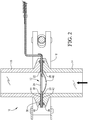
Fig. 2 is a cross-sectional view of the pressure relief assembly ofFig. 1 ; -
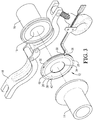
Fig. 3 is an exploded view of the pressure relief assembly ofFig. 1 ; -
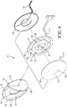
Fig. 4 is an exploded view of the rupture disc assembly including a burst indicator made in accordance with the present invention; -
Fig. 5 is a plan view of a burst indicator made in accordance with the present invention; -
Fig. 6 is a cross-sectional view of the burst indicator taken along line 6-6 ofFig. 5 ; and -
Fig. 7 is a close up, perspective view of the severable bridge feature of the burst indicator ofFig. 5 . - The following description illustrates certain embodiments of the present invention and nothing therein should be taken as a limitation upon the overall scope of the invention. Turning to
Fig. 1 , apressure relief assembly 10 according to one embodiment of the present invention is shown.Assembly 10 generally comprises arupture disc assembly 12 interposed between a pair offerrules Rupture disc assembly 12 is secured betweenferrules clamp 18. - When installed in
pressure relief assembly 10,rupture disc assembly 12 is essentially hidden from operator view. Thus, in certain applications, it is desirable to use a sensor to monitor the integrity of therupture disc assembly 12 and alert an operator should the rupture disc assembly fail thereby permitting communication betweenferrule bores ferrules - It was discovered that "strip-type" burst indicators such as disclosed in
US. Patent No. 4,342,988 affected the burst characteristics of some rupture discs to an unacceptable degree when secured along with rupture disc assembly 1 2 betweenferrules ferrules - As shown in
Figs. 2-4 ,rupture disc assembly 12 comprises arupture disc 20, asupport member 22, and aburst indicator 24 that are disposed within agasket 26.Gasket 26 comprisesplies circumferential sidewall 32 and includes acentral orifice 34. Aslit 36 is formed in a portion ofsidewall 32 to permit insertion ofdisc 20,support member 22, andburst indicator 24 in betweenplies ply gasket 26 includes a generally circular o-ring bead inboard flange section - As shown,
rupture disc 20 comprises a reverse-acting rupture disc having a concavo-convex (i.e., bulged or domed) centralrupturable portion 46. However, it is within the scope of the present invention to employ forward-acting bulged discs and un-bulged or flat rupture discs. Exemplary rupture discs for use in accordance with the present invention are described inU.S. Patent No. 6,945,420 . - As illustrated in
Fig. 4 ,support member 22 comprises an annularinner hub 48, an outerperipheral portion 50 radially spaced frominner hub 48, and one ormore connector segments 52 extending betweeninner hub 48 and outerperipheral portion 50.Connector segments 52, in cooperation with outer peripheral portioninner margin 54 and inner hubouter margin 56, define one ormore apertures 58 insupport member 22.Support member 22, and particularlyinner hub 48, optionally comprises an inwardly extendingtongue 60 andtooth 62.Tongue 60 extends into the support membercentral orifice 64 and is configured to prevent fragmentation ofdisc 20 during rupture. The illustrated support member is described in further detail inU.S. Patent Application No. 12/422,851, filed April 13, 2009 support member 22. - One embodiment of a
burst indicator 24 in accordance with the present invention is shown inFig. 5 .Burst indicator 24 comprises an outerannular portion 66 and aninner section 68.Annular portion 66 andinner section 68 are joined together by first and second bridge features 70, 72, respectively. Outerannular portion 66 andinner section 68 are further isolated from each other by arcuately-shapedapertures - Electrically
conductive segments rupture disc 20. In certain embodiments,segment 78 is located entirely upon outerannular portion 66 and extends substantially around the entire circumference ofportion 66, except for a very smallvoid area 82 that is defined by firstsegment end regions segment 78 does not extend across any part ofinner section 68.Segment 80 extends from outerannular portion 66, and particularly throughvoid area 82, acrossbridge feature 70, and ontoinner section 68. At approximately the center ofinner section 68,segment 80 experiences a change in direction and extends acrossbridge feature 72 and back onto outerannular portion 66. As shown,segment 80 changes direction by approximately 60°, although in alternate embodiments, this angle may be greater or less. In still other embodiments,segment 80 need not change direction at all and continue along a straight path throughinner section 68. The orientation ofbridge feature 72 is changed to accommodate the path ofsegment 80.Segment 80 joins withsegment 78 at ajunction point 88 located near the outer periphery of outerannular portion 66 to form a circuit. - Outer
annular portion 66 andinner section 68 generally comprise a non-elcctrically conductive membrane. In one embodiment, the membrane is a laminate structure which comprises at least two layers of a synthetic resin film material, such as a polyimide film available under the trade name Kapton®. In certain embodiments, particularly as shown inFig. 6 , burstindicator 24 comprises outer synthetic resin film layers 90, 92, two intermediate layers of an adhesive 94, 96, such as an acrylic-based adhesive, and a centralconductive layer 98 from whichsegments conductive layer 98 may comprise any suitable electrically conductive material, such as copper or silver, or as discussed in further detail below, both copper and silver. Note, it is within the scope of the present invention forburst indicator 24 to be of alternate construction, such as, for example, a single sheet of film having a conductive layer applied thereto or imprinted thereon. - Electrically
conductive segment 78 comprises anarcuate segment 100 that extends fromjunction 88 to endregion 86.Segment 100 does not form a part of the circuit, rather, it provides a certain degree of uniformity of thickness, and therefore structural loading, to the outer periphery of outerannular portion 66. Ifsegment 100 were not present, the thickness of outerannular portion 66 in this area would be different from the thickness of outerannular portion 66 in the area ofsegment 78. When inserted and clamped betweenferrules rupture disc 20 thereby altering its opening characteristics. By providingsegment 100, even though it does not form a part of the circuit, the creation of these stress regions is avoided. The impact ofvoid area 82 upon structural loading is lessened assegment 80 extends therethrough leaving only minute areas that are not occupied by electrically conductive material. In certain embodiments,segment 78 has a length that is at least about 90% of the outer circumference of outerannular portion 66. In other embodiments, this length is at least about 95% of the outer circumference of outerannular portion 66. - At least one of bridge features 70, 72 may include a weakened area that aids and/or defines an initiating point for the tearing of that bridge feature. In certain embodiments, the respective bridge feature separates from outer
annular portion 66 upon rupture of the rupture disc. In alternate embodiments, the bridge feature may separate frominner section 68 while remaining attached to outerannular portion 66. In still other embodiments, the bridge feature may tear at some point in between outerannular portion 66 andinner section 68. - It was observed that the flat Kapton®, adhesive, and metallic conducting materials from which burst indicator circuits are made tear more easily when a twisting moment is applied to a bridge feature in which a starting slit has been provided, due to the enhanced concentration of stress at the tip of the slit. This twisting moment may be achieved in various ways. In one embodiment, the inclusion of an angle in
segment 80places bridge feature 72 off-center with respect to the opening central rupturable portion (petal) of a single-petal hinged rupture disc. In another embodiment, bridge features 70, 72 may or may not be co-axially aligned with each other and the entire central portion of theburst indicator 24 could be placed off center relative to the centerline or line of symmetry of centralrupturable portion 46 of a single-petal hingedrupture disc 20. In yet another embodiment, the central portion of theburst indicator 24 is centered relative to the centerpoint of therupturable portion 46, and bridge features 70, 72 are skewed at an angle relative to the line-of-symmetry of the rupture disc petal, while they may or may not be co-axially aligned with each other. - Irrespective of the configuration, in these embodiments, as the petal imparts force to the
inner section 68 of the burst indicator, the desired twisting moment is imparted to bridgefeature 72, and stress is concentrated at the tip ofslit 102, facilitating the opening of the circuit. In one embodiment, only one weakened area for initiation of separation is included, as shown atbridge feature 72 inFig. 7 . This elimination of additional weakened areas will have the effect of concentrating stress and energy at a single point instead of two or more points, thus leading to enhanced performance during separation. As shown inFig. 7 .bridge feature 72 includes aslit 102 having an open end that communicates withaperture 76. Upon opening ofrupture disc 20, centralrupturable portion 46 contactsinner section 68 and places a stress on bridge features 70, 72. As can be seen in the Figures,bridge feature 72 is generally narrower thanbridge feature 70 and offset therefrom.Slit 102 serves to further weakenbridge feature 72, concentrating stress at the tip ofslit 102, so that it will more easily detach from outerannular portion 66 thereby severingsegment 80 and opening the circuit. Upon detachment ofbridge feature 72,inner section 68 is able to pivot aboutbridge feature 70 which acts as a hinge. Thus, because ofbridge feature 70,inner section 68 does not fragment and remains attached to outerannular portion 66. - Note that slit 102, as shown in
Fig. 7 , is angled inwardly towardinner section 68. This slight angle optimizes tearing direction across the metallic conductive segment. The copper material, in particular, has a much higher strength and energy of rupture than the nonconductive material. Due to this difference, the path of material separation tends to change direction at the edge of the copper segment. Ideally, the path would proceed along the shortest distance across the copper, thus using the least energy to effect circuit separation. The path, as it reaches the edge of the metallic segment, tends to change direction away from the petal. Thus, the optimal path of separation before that point would be angled inward toward the petal. - In one embodiment according to the present invention, electrically
conductive segment 80 may comprise primarily copper, with the exception that at least a portion ofsegment 80, particularly that portion which extends acrossbridge 72, comprises silver. Silver, especially when printed as ink, has a lower resistance to tearing than copper. Thus, using silver to form the severable portion ofsegment 80 can, in certain embodiments, be desirable. - As shown in
Fig. 4 , in one embodiment, burstindicator 24 can be assembled withsupport member 22 andrupture disc 20 so as to form an integrated unit that is placed withingasket 26. When placed withingasket 26, burstindicator 24 is positioned downstream fromrupture disc 20 andsupport member 22 is located therebetween. Gasketcentral orifice 34 is in registry with centralrupturable portion 46 andinner section 68. In certain embodiments,rupture disc 20 is a reverse-acting rupture disc having a concavo-convexrupturable portion 46. The burst indicator may be locatedadjacent disc 20, separated therefrom bysupport member 22, in facing relationship to the concave side ofrupturable portion 46. It is also within the scope of the present invention forsupport member 22 to be eliminated from the rupture disc assembly so that outerannular portion 66 is in direct, face-to-face contact with rupture discouter annulus portion 47. If a forward-acting, bulged disc is to be used, burstindicator 24 may need to be positioned further downstream from the rupture disc, or be configured to have a bulged shape wherebyinner section 68 roughly conforms with the convex surface of the forward-acting disc but does not come into contact with it until the bulged section of the disc has ruptured. By supplying these components as an integrated assembly, installation errors, and consequently operational malfunctions, can be reduced. -
Burst indicator 24, in certain embodiments, is provided with atag 104 comprising conductive leads 106 ,108 that are joined with electricallyconductive segments Tag 104 may then be operably connected with anadapter plug 110, as shown inFig. 1 , or other similar structure so that the burst indicator circuit may be integrated with a larger monitoring system.Tag 104 also tends to be configured similarly to supportmember tag 112, so that the two tags can be mated for installation. As shown inFig. 4 ,rupture disc 20 may also be provided with atag 114, although, in this embodiment,tag 114 is not as long as either oftags tag 112 to assist with, ensure and visually indicate proper installation of the correctrupture disc assembly 12 within a designatedpressure relief assembly 10. - It is also within the scope of the present invention for
burst indicator 24 to be used in applications that do not utilizeferrules - The present invention also provides methods of monitoring the status of
rupture disc 20 by providing aburst indicator 24 according to any embodiment described above and positioning the burst indicator in proximity to the rupture disc.Burst indicator 24 can be operably connected with a monitoring system configured to alert an operator of a change in the integrity of the rupture disc. Upon opening ofrupture disc 20, as discussed above,rupturable portion 46 physically contactsinner section 68 and causesbridge feature 72 to separate from outerannular portion 66 thereby severingconductive segment 80 and opening the circuit. The opening of the circuit causes the monitoring system to alert the operator thatdisc 20 has burst.
Claims (14)
- A burst indicator (24) for use with a rupture disc comprising:a non-electrically conductive material having an outer annular portion (66) and an inner section (68) joined to said outer annular portion (66) by at least first and second bridge features (70, 72); andan electrical circuit comprising at least first and second electrically conductive segments (78, 80), said first segment (78) being located upon said outer annular portion (66), and said second segment (80) extending from said outer annular portion (66), across said first bridge feature (70) onto said inner section (68) and across said second bridge feature (72) onto said outer annular portion (66) where it connects with said first segment (78),wherein at least one of said first and second bridge features (70, 72) is configured to tear at a point between said outer annular portion (66) and said inner section (68) upon opening of said rupture disc thereby detaching at least a portion of said at least one of said first and second bridge features (70, 72) from said outer annular portion (66) or said inner section (68), severing said second segment (80), and opening said circuit,characterized in that said first segment (78) extends circumferentially about said outer annular portion (66) and is defined by a pair of spaced-apart end regions (84, 86), and in that said second segment (80) extends between said end regions (84, 86) toward said first bridge feature (70).
- The burst indicator (24) according to claim 1, wherein said outer annular portion (66) and said inner section (68) comprise a non-electrically conductive membrane.
- The burst indicator (24) according to claim 1, wherein said first electrically conductive segment (78) is located adjacent the outer periphery of said outer annular portion (66) and has a length that is at least about 90% of the outer circumference of said outer annular portion (66).
- The burst indicator (24) according to claim 1, wherein said second bridge feature (72) is offset from said first bridge feature (70).
- The burst indicator (24) according to claim 1, wherein said second bridge feature (72) is configured to tear thereby resulting in severing of said second electrically conductive segment (80).
- The burst indicator (24) according to claim 5, wherein said second bridge feature (72) includes a weakened area that assists in the tearing of said second bridge feature (72) and severing of said second electrically conductive segment (80).
- The burst indicator (24) according to claim 6, said weakened area comprising a slit (102) formed in said second bridge feature (72).
- The burst indicator (24) according to claim 1, said first electrically conductive segment (78) comprising an arcuate segment that does not form a part of said circuit.
- The burst indicator (24) according to claim 1, wherein said first electrically conductive segment (78) does not extend across said inner section (68).
- A rupture disc assembly (12) comprising:a rupture disc (20) having a rupturable central section (46); andthe burst indicator (24) of any of claims 1-9 for signaling rupture of said rupturable central section (46).
- The rupture disc assembly (12) according to claim 10, wherein said rupture disc assembly (12) further comprises a support member (22) interposed between said rupture disc (20) and said burst indicator (24).
- The rupture disc assembly (12) according to claim 11, wherein said rupture disc (20), support member (22), and burst indicator (24) are positioned between adjacent plies (28, 30) of an elastomeric gasket (26), each ply (28, 30) of said elastomeric gasket (26) having a central orifice (64) in registry with said central rupturable section (46) of said rupture disc (20).
- A method of monitoring the status of a rupture disc (20) positioned within a fluid passageway comprising:providing a burst indicator (24) comprising a non-electrically conductive material having an outer annular portion (66) and an inner section (68) joined to said outer annular portion (66) by at least first and second bridge features (70, 72), and an electrical circuit comprising at least first and second electrically conductive segments (78, 80), said first segment (78) being located upon and extending circumferentially about said outer annular portion (66) and being defined by a pair of spaced-apart end regions (84, 86), and said second segment (80) extending from said outer annular portion (66), across said first bridge feature (70) onto said inner section (68) and across said second bridge feature (72) onto said outer annular portion (66) where it connects with said first segment (78), wherein said second segment (80) extends between said end regions (84, 86) toward said first bridge feature (70); andpositioning said burst indicator (24) within said fluid passageway such that the action of said rupture disc (20) in response to existence of a sufficient pressure condition within said fluid passageway will cause at least one of said first and second bridge features (70, 72) to tear at a point between said outer annular portion (66) and said inner section (68) upon opening of said rupture disc, thereby detaching at least a portion of said at least one of said first and second bridge features (70, 72) from said outer annular portion (66) or said inner section (68), severing said second electrically conductive segment (80) and opening said circuit.
- The method according to claim 13, wherein said burst indicator (24) is positioned so that a rupturable portion (46) of said rupture disc (20) physically contacts said inner section (68) upon opening of said rupture disc (20) and causes at least one of said first and second bridge features (70, 72) to tear.
Applications Claiming Priority (2)
| Application Number | Priority Date | Filing Date | Title |
|---|---|---|---|
| US12/815,252 US8354934B2 (en) | 2010-06-14 | 2010-06-14 | Burst indicator |
| PCT/US2011/024239 WO2011159368A1 (en) | 2010-06-14 | 2011-02-09 | Burst indicator |
Publications (3)
| Publication Number | Publication Date |
|---|---|
| EP2580746A1 EP2580746A1 (en) | 2013-04-17 |
| EP2580746A4 EP2580746A4 (en) | 2017-01-25 |
| EP2580746B1 true EP2580746B1 (en) | 2019-08-07 |
Family
ID=45095341
Family Applications (1)
| Application Number | Title | Priority Date | Filing Date |
|---|---|---|---|
| EP11796102.9A Active EP2580746B1 (en) | 2010-06-14 | 2011-02-09 | Burst indicator |
Country Status (13)
| Country | Link |
|---|---|
| US (1) | US8354934B2 (en) |
| EP (1) | EP2580746B1 (en) |
| JP (1) | JP5793189B2 (en) |
| KR (1) | KR101792897B1 (en) |
| CN (1) | CN103038801B (en) |
| AU (1) | AU2011265732B2 (en) |
| BR (1) | BR112012031835A2 (en) |
| CA (1) | CA2802457C (en) |
| EG (1) | EG26898A (en) |
| MX (1) | MX2012014657A (en) |
| RU (1) | RU2511862C1 (en) |
| SG (1) | SG186337A1 (en) |
| WO (1) | WO2011159368A1 (en) |
Families Citing this family (10)
| Publication number | Priority date | Publication date | Assignee | Title |
|---|---|---|---|---|
| NO336176B1 (en) * | 2012-08-24 | 2015-06-01 | Depro As | Pipe clamp fitted with bias reader and use of bias reader on a tube clamp |
| US9049358B2 (en) * | 2013-09-18 | 2015-06-02 | Extend-N-Click, Llc | Camera extension apparatus and method using a switch for taking pictures at a distance from a user |
| CN104006209B (en) * | 2014-05-22 | 2016-08-24 | 国家电网公司 | Indoor pressure vessel relief valve action display device |
| CA2960106A1 (en) * | 2014-09-08 | 2016-03-17 | Fike Corporation | Pressure relief device having conductive ink sensors formed thereon |
| AU2016348531B2 (en) | 2015-11-06 | 2022-04-14 | Oklahoma Safety Equipment Company, Inc. | Rupture disc device and method of assembly thereof |
| US10527183B1 (en) | 2017-05-01 | 2020-01-07 | KHOLLE Magnolia 2015, LLC | Pressure relief valve |
| US10436341B1 (en) | 2017-10-20 | 2019-10-08 | KHOLLE Magnolia 2015, LLC | Pressure relief valves |
| DE102018119144A1 (en) * | 2018-08-07 | 2020-02-13 | R. Stahl Schaltgeräte GmbH | Pressure relief device and housing with such |
| US11933413B2 (en) * | 2022-07-26 | 2024-03-19 | Oseco Inc. | Support structure for a reverse buckling rupture disc |
| US20250164031A1 (en) * | 2023-11-10 | 2025-05-22 | Fike Corporation | Pressure relief device having conductive trace sensor formed thereon |
Family Cites Families (19)
| Publication number | Priority date | Publication date | Assignee | Title |
|---|---|---|---|---|
| US4342988A (en) | 1980-01-25 | 1982-08-03 | Continental Disc Corporation | Rupture disc alarm system |
| JPS62177382A (en) | 1986-01-27 | 1987-08-04 | Power Reactor & Nuclear Fuel Dev Corp | Bursting plate type safety device |
| CA1290641C (en) | 1988-06-24 | 1991-10-15 | Stephen Farwell | Composite rupture disk assembly |
| US4978947A (en) * | 1989-05-25 | 1990-12-18 | Bs&B Safety Systems, Inc. | Rupturable fluid flow indicator |
| US5155471A (en) | 1991-06-21 | 1992-10-13 | Bs&B Safety Systems, Inc. | Low pressure burst disk sensor with weakened conductive strips |
| DE4140089A1 (en) | 1991-12-05 | 1993-06-09 | Hoechst Ag, 6230 Frankfurt, De | Rupture disc |
| US5313194A (en) | 1992-04-14 | 1994-05-17 | Varos Richard V | Rupture disk sensing assembly |
| US5583490A (en) | 1994-07-15 | 1996-12-10 | Htv Industries, Inc. | Rupture disk monitoring apparatus |
| US5631634A (en) | 1995-01-11 | 1997-05-20 | Oklahoma Safety Equipment Co. | Flow and pressure sensor |
| US5934308A (en) | 1995-10-24 | 1999-08-10 | Bs&B Safety Systems, Inc. | Rupture disk apparatus and methods |
| US5661277A (en) * | 1995-12-01 | 1997-08-26 | Oklahoma Safety Equipment Co. | Differential pressure flow sensor using multiple layers of flexible membranes |
| US5657001A (en) * | 1996-04-16 | 1997-08-12 | Oklahoma Safety Equipment Company | Fluid flow detector |
| US6006938A (en) | 1997-09-18 | 1999-12-28 | Continental Disc Corporation | Enhanced reverse buckling rupture disc |
| US6631668B1 (en) | 2000-11-10 | 2003-10-14 | David Wilson | Recoilless impact device |
| US6318576B1 (en) | 2000-11-21 | 2001-11-20 | Oklahoma Safety Equipment Co., Inc. | Sanitary rupture disk apparatus |
| US6598454B2 (en) | 2001-07-30 | 2003-07-29 | Bs&B Safety Systems, Inc. | System and method for monitoring a pressurized system |
| US6945420B2 (en) * | 2003-03-28 | 2005-09-20 | Fike Corporation | Reverse buckling sanitary rupture disc assembly |
| US7600527B2 (en) * | 2005-04-01 | 2009-10-13 | Fike Corporation | Reverse acting rupture disc with laser-defined electropolished line of weakness and method of forming the line of weakness |
| EP2149169B8 (en) | 2007-05-08 | 2017-10-18 | BS&B Innovations Limited | Pressure response membrane |
-
2010
- 2010-06-14 US US12/815,252 patent/US8354934B2/en not_active Expired - Fee Related
-
2011
- 2011-02-09 BR BR112012031835A patent/BR112012031835A2/en not_active Application Discontinuation
- 2011-02-09 WO PCT/US2011/024239 patent/WO2011159368A1/en not_active Ceased
- 2011-02-09 EP EP11796102.9A patent/EP2580746B1/en active Active
- 2011-02-09 CA CA2802457A patent/CA2802457C/en not_active Expired - Fee Related
- 2011-02-09 AU AU2011265732A patent/AU2011265732B2/en not_active Ceased
- 2011-02-09 MX MX2012014657A patent/MX2012014657A/en active IP Right Grant
- 2011-02-09 JP JP2013515327A patent/JP5793189B2/en not_active Expired - Fee Related
- 2011-02-09 CN CN201180036194.5A patent/CN103038801B/en not_active Expired - Fee Related
- 2011-02-09 KR KR1020127033572A patent/KR101792897B1/en not_active Expired - Fee Related
- 2011-02-09 RU RU2013101570/06A patent/RU2511862C1/en not_active IP Right Cessation
- 2011-02-09 SG SG2012091856A patent/SG186337A1/en unknown
-
2012
- 2012-12-16 EG EG2012122064A patent/EG26898A/en active
Non-Patent Citations (1)
| Title |
|---|
| None * |
Also Published As
| Publication number | Publication date |
|---|---|
| AU2011265732A1 (en) | 2013-01-24 |
| BR112012031835A2 (en) | 2016-11-08 |
| EP2580746A1 (en) | 2013-04-17 |
| RU2511862C1 (en) | 2014-04-10 |
| US8354934B2 (en) | 2013-01-15 |
| CA2802457C (en) | 2018-07-31 |
| CN103038801A (en) | 2013-04-10 |
| CN103038801B (en) | 2016-06-08 |
| CA2802457A1 (en) | 2011-12-22 |
| SG186337A1 (en) | 2013-01-30 |
| KR20130126452A (en) | 2013-11-20 |
| WO2011159368A1 (en) | 2011-12-22 |
| EG26898A (en) | 2014-12-04 |
| KR101792897B1 (en) | 2017-11-02 |
| US20110303523A1 (en) | 2011-12-15 |
| AU2011265732B2 (en) | 2014-09-18 |
| JP2013538990A (en) | 2013-10-17 |
| MX2012014657A (en) | 2013-02-07 |
| JP5793189B2 (en) | 2015-10-14 |
| EP2580746A4 (en) | 2017-01-25 |
Similar Documents
| Publication | Publication Date | Title |
|---|---|---|
| US8354934B2 (en) | Burst indicator | |
| US4978947A (en) | Rupturable fluid flow indicator | |
| EP0519585B1 (en) | Low pressure burst disk sensor | |
| US5631634A (en) | Flow and pressure sensor | |
| US20160069474A1 (en) | Pressure relief device having conductive ink sensors formed thereon | |
| CA2769452C (en) | Pressure relief device integrity sensor | |
| JPH04211773A (en) | Low-pressure non-fragmenting breaking disk | |
| JP2013538990A5 (en) | ||
| US8091574B2 (en) | Bursting disc assembly | |
| US5661277A (en) | Differential pressure flow sensor using multiple layers of flexible membranes | |
| HK1180098A (en) | Burst indicator | |
| HK1180098B (en) | Burst indicator | |
| US20250164031A1 (en) | Pressure relief device having conductive trace sensor formed thereon | |
| HK1237020A1 (en) | Pressure relief device having conductive ink sensors formed thereon |
Legal Events
| Date | Code | Title | Description |
|---|---|---|---|
| PUAI | Public reference made under article 153(3) epc to a published international application that has entered the european phase |
Free format text: ORIGINAL CODE: 0009012 |
|
| 17P | Request for examination filed |
Effective date: 20130114 |
|
| AK | Designated contracting states |
Kind code of ref document: A1 Designated state(s): AL AT BE BG CH CY CZ DE DK EE ES FI FR GB GR HR HU IE IS IT LI LT LU LV MC MK MT NL NO PL PT RO RS SE SI SK SM TR |
|
| DAX | Request for extension of the european patent (deleted) | ||
| RA4 | Supplementary search report drawn up and despatched (corrected) |
Effective date: 20170103 |
|
| RIC1 | Information provided on ipc code assigned before grant |
Ipc: G08B 21/00 20060101AFI20161221BHEP |
|
| STAA | Information on the status of an ep patent application or granted ep patent |
Free format text: STATUS: EXAMINATION IS IN PROGRESS |
|
| 17Q | First examination report despatched |
Effective date: 20171130 |
|
| GRAP | Despatch of communication of intention to grant a patent |
Free format text: ORIGINAL CODE: EPIDOSNIGR1 |
|
| STAA | Information on the status of an ep patent application or granted ep patent |
Free format text: STATUS: GRANT OF PATENT IS INTENDED |
|
| INTG | Intention to grant announced |
Effective date: 20190306 |
|
| GRAS | Grant fee paid |
Free format text: ORIGINAL CODE: EPIDOSNIGR3 |
|
| GRAA | (expected) grant |
Free format text: ORIGINAL CODE: 0009210 |
|
| STAA | Information on the status of an ep patent application or granted ep patent |
Free format text: STATUS: THE PATENT HAS BEEN GRANTED |
|
| AK | Designated contracting states |
Kind code of ref document: B1 Designated state(s): AL AT BE BG CH CY CZ DE DK EE ES FI FR GB GR HR HU IE IS IT LI LT LU LV MC MK MT NL NO PL PT RO RS SE SI SK SM TR |
|
| REG | Reference to a national code |
Ref country code: GB Ref legal event code: FG4D |
|
| REG | Reference to a national code |
Ref country code: CH Ref legal event code: EP Ref country code: AT Ref legal event code: REF Ref document number: 1165045 Country of ref document: AT Kind code of ref document: T Effective date: 20190815 |
|
| REG | Reference to a national code |
Ref country code: DE Ref legal event code: R096 Ref document number: 602011061101 Country of ref document: DE |
|
| REG | Reference to a national code |
Ref country code: IE Ref legal event code: FG4D |
|
| REG | Reference to a national code |
Ref country code: NL Ref legal event code: MP Effective date: 20190807 |
|
| REG | Reference to a national code |
Ref country code: LT Ref legal event code: MG4D |
|
| PG25 | Lapsed in a contracting state [announced via postgrant information from national office to epo] |
Ref country code: FI Free format text: LAPSE BECAUSE OF FAILURE TO SUBMIT A TRANSLATION OF THE DESCRIPTION OR TO PAY THE FEE WITHIN THE PRESCRIBED TIME-LIMIT Effective date: 20190807 Ref country code: BG Free format text: LAPSE BECAUSE OF FAILURE TO SUBMIT A TRANSLATION OF THE DESCRIPTION OR TO PAY THE FEE WITHIN THE PRESCRIBED TIME-LIMIT Effective date: 20191107 Ref country code: NL Free format text: LAPSE BECAUSE OF FAILURE TO SUBMIT A TRANSLATION OF THE DESCRIPTION OR TO PAY THE FEE WITHIN THE PRESCRIBED TIME-LIMIT Effective date: 20190807 Ref country code: NO Free format text: LAPSE BECAUSE OF FAILURE TO SUBMIT A TRANSLATION OF THE DESCRIPTION OR TO PAY THE FEE WITHIN THE PRESCRIBED TIME-LIMIT Effective date: 20191107 Ref country code: SE Free format text: LAPSE BECAUSE OF FAILURE TO SUBMIT A TRANSLATION OF THE DESCRIPTION OR TO PAY THE FEE WITHIN THE PRESCRIBED TIME-LIMIT Effective date: 20190807 Ref country code: LT Free format text: LAPSE BECAUSE OF FAILURE TO SUBMIT A TRANSLATION OF THE DESCRIPTION OR TO PAY THE FEE WITHIN THE PRESCRIBED TIME-LIMIT Effective date: 20190807 Ref country code: PT Free format text: LAPSE BECAUSE OF FAILURE TO SUBMIT A TRANSLATION OF THE DESCRIPTION OR TO PAY THE FEE WITHIN THE PRESCRIBED TIME-LIMIT Effective date: 20191209 Ref country code: HR Free format text: LAPSE BECAUSE OF FAILURE TO SUBMIT A TRANSLATION OF THE DESCRIPTION OR TO PAY THE FEE WITHIN THE PRESCRIBED TIME-LIMIT Effective date: 20190807 |
|
| REG | Reference to a national code |
Ref country code: AT Ref legal event code: MK05 Ref document number: 1165045 Country of ref document: AT Kind code of ref document: T Effective date: 20190807 |
|
| PG25 | Lapsed in a contracting state [announced via postgrant information from national office to epo] |
Ref country code: AL Free format text: LAPSE BECAUSE OF FAILURE TO SUBMIT A TRANSLATION OF THE DESCRIPTION OR TO PAY THE FEE WITHIN THE PRESCRIBED TIME-LIMIT Effective date: 20190807 Ref country code: RS Free format text: LAPSE BECAUSE OF FAILURE TO SUBMIT A TRANSLATION OF THE DESCRIPTION OR TO PAY THE FEE WITHIN THE PRESCRIBED TIME-LIMIT Effective date: 20190807 Ref country code: IS Free format text: LAPSE BECAUSE OF FAILURE TO SUBMIT A TRANSLATION OF THE DESCRIPTION OR TO PAY THE FEE WITHIN THE PRESCRIBED TIME-LIMIT Effective date: 20191207 Ref country code: GR Free format text: LAPSE BECAUSE OF FAILURE TO SUBMIT A TRANSLATION OF THE DESCRIPTION OR TO PAY THE FEE WITHIN THE PRESCRIBED TIME-LIMIT Effective date: 20191108 Ref country code: LV Free format text: LAPSE BECAUSE OF FAILURE TO SUBMIT A TRANSLATION OF THE DESCRIPTION OR TO PAY THE FEE WITHIN THE PRESCRIBED TIME-LIMIT Effective date: 20190807 Ref country code: ES Free format text: LAPSE BECAUSE OF FAILURE TO SUBMIT A TRANSLATION OF THE DESCRIPTION OR TO PAY THE FEE WITHIN THE PRESCRIBED TIME-LIMIT Effective date: 20190807 |
|
| PG25 | Lapsed in a contracting state [announced via postgrant information from national office to epo] |
Ref country code: TR Free format text: LAPSE BECAUSE OF FAILURE TO SUBMIT A TRANSLATION OF THE DESCRIPTION OR TO PAY THE FEE WITHIN THE PRESCRIBED TIME-LIMIT Effective date: 20190807 |
|
| PG25 | Lapsed in a contracting state [announced via postgrant information from national office to epo] |
Ref country code: EE Free format text: LAPSE BECAUSE OF FAILURE TO SUBMIT A TRANSLATION OF THE DESCRIPTION OR TO PAY THE FEE WITHIN THE PRESCRIBED TIME-LIMIT Effective date: 20190807 Ref country code: PL Free format text: LAPSE BECAUSE OF FAILURE TO SUBMIT A TRANSLATION OF THE DESCRIPTION OR TO PAY THE FEE WITHIN THE PRESCRIBED TIME-LIMIT Effective date: 20190807 Ref country code: DK Free format text: LAPSE BECAUSE OF FAILURE TO SUBMIT A TRANSLATION OF THE DESCRIPTION OR TO PAY THE FEE WITHIN THE PRESCRIBED TIME-LIMIT Effective date: 20190807 Ref country code: AT Free format text: LAPSE BECAUSE OF FAILURE TO SUBMIT A TRANSLATION OF THE DESCRIPTION OR TO PAY THE FEE WITHIN THE PRESCRIBED TIME-LIMIT Effective date: 20190807 Ref country code: RO Free format text: LAPSE BECAUSE OF FAILURE TO SUBMIT A TRANSLATION OF THE DESCRIPTION OR TO PAY THE FEE WITHIN THE PRESCRIBED TIME-LIMIT Effective date: 20190807 |
|
| PG25 | Lapsed in a contracting state [announced via postgrant information from national office to epo] |
Ref country code: CZ Free format text: LAPSE BECAUSE OF FAILURE TO SUBMIT A TRANSLATION OF THE DESCRIPTION OR TO PAY THE FEE WITHIN THE PRESCRIBED TIME-LIMIT Effective date: 20190807 Ref country code: SK Free format text: LAPSE BECAUSE OF FAILURE TO SUBMIT A TRANSLATION OF THE DESCRIPTION OR TO PAY THE FEE WITHIN THE PRESCRIBED TIME-LIMIT Effective date: 20190807 Ref country code: IS Free format text: LAPSE BECAUSE OF FAILURE TO SUBMIT A TRANSLATION OF THE DESCRIPTION OR TO PAY THE FEE WITHIN THE PRESCRIBED TIME-LIMIT Effective date: 20200224 Ref country code: SM Free format text: LAPSE BECAUSE OF FAILURE TO SUBMIT A TRANSLATION OF THE DESCRIPTION OR TO PAY THE FEE WITHIN THE PRESCRIBED TIME-LIMIT Effective date: 20190807 |
|
| REG | Reference to a national code |
Ref country code: DE Ref legal event code: R097 Ref document number: 602011061101 Country of ref document: DE |
|
| PLBE | No opposition filed within time limit |
Free format text: ORIGINAL CODE: 0009261 |
|
| STAA | Information on the status of an ep patent application or granted ep patent |
Free format text: STATUS: NO OPPOSITION FILED WITHIN TIME LIMIT |
|
| PG2D | Information on lapse in contracting state deleted |
Ref country code: IS |
|
| 26N | No opposition filed |
Effective date: 20200603 |
|
| PG25 | Lapsed in a contracting state [announced via postgrant information from national office to epo] |
Ref country code: SI Free format text: LAPSE BECAUSE OF FAILURE TO SUBMIT A TRANSLATION OF THE DESCRIPTION OR TO PAY THE FEE WITHIN THE PRESCRIBED TIME-LIMIT Effective date: 20190807 |
|
| REG | Reference to a national code |
Ref country code: DE Ref legal event code: R119 Ref document number: 602011061101 Country of ref document: DE |
|
| REG | Reference to a national code |
Ref country code: CH Ref legal event code: PL |
|
| GBPC | Gb: european patent ceased through non-payment of renewal fee |
Effective date: 20200209 |
|
| REG | Reference to a national code |
Ref country code: BE Ref legal event code: MM Effective date: 20200229 |
|
| PG25 | Lapsed in a contracting state [announced via postgrant information from national office to epo] |
Ref country code: MC Free format text: LAPSE BECAUSE OF FAILURE TO SUBMIT A TRANSLATION OF THE DESCRIPTION OR TO PAY THE FEE WITHIN THE PRESCRIBED TIME-LIMIT Effective date: 20190807 Ref country code: LU Free format text: LAPSE BECAUSE OF NON-PAYMENT OF DUE FEES Effective date: 20200209 |
|
| PG25 | Lapsed in a contracting state [announced via postgrant information from national office to epo] |
Ref country code: CH Free format text: LAPSE BECAUSE OF NON-PAYMENT OF DUE FEES Effective date: 20200229 Ref country code: LI Free format text: LAPSE BECAUSE OF NON-PAYMENT OF DUE FEES Effective date: 20200229 |
|
| PG25 | Lapsed in a contracting state [announced via postgrant information from national office to epo] |
Ref country code: GB Free format text: LAPSE BECAUSE OF NON-PAYMENT OF DUE FEES Effective date: 20200209 Ref country code: FR Free format text: LAPSE BECAUSE OF NON-PAYMENT OF DUE FEES Effective date: 20200229 Ref country code: IE Free format text: LAPSE BECAUSE OF NON-PAYMENT OF DUE FEES Effective date: 20200209 Ref country code: DE Free format text: LAPSE BECAUSE OF NON-PAYMENT OF DUE FEES Effective date: 20200901 |
|
| PG25 | Lapsed in a contracting state [announced via postgrant information from national office to epo] |
Ref country code: BE Free format text: LAPSE BECAUSE OF NON-PAYMENT OF DUE FEES Effective date: 20200229 |
|
| PG25 | Lapsed in a contracting state [announced via postgrant information from national office to epo] |
Ref country code: IT Free format text: LAPSE BECAUSE OF NON-PAYMENT OF DUE FEES Effective date: 20200209 |
|
| PG25 | Lapsed in a contracting state [announced via postgrant information from national office to epo] |
Ref country code: MT Free format text: LAPSE BECAUSE OF FAILURE TO SUBMIT A TRANSLATION OF THE DESCRIPTION OR TO PAY THE FEE WITHIN THE PRESCRIBED TIME-LIMIT Effective date: 20190807 Ref country code: CY Free format text: LAPSE BECAUSE OF FAILURE TO SUBMIT A TRANSLATION OF THE DESCRIPTION OR TO PAY THE FEE WITHIN THE PRESCRIBED TIME-LIMIT Effective date: 20190807 |
|
| PG25 | Lapsed in a contracting state [announced via postgrant information from national office to epo] |
Ref country code: MK Free format text: LAPSE BECAUSE OF FAILURE TO SUBMIT A TRANSLATION OF THE DESCRIPTION OR TO PAY THE FEE WITHIN THE PRESCRIBED TIME-LIMIT Effective date: 20190807 |
|
| P01 | Opt-out of the competence of the unified patent court (upc) registered |
Effective date: 20230529 |