EP2580716B2 - Monitoring the stock in flow racks using rfid - Google Patents
Monitoring the stock in flow racks using rfid Download PDFInfo
- Publication number
- EP2580716B2 EP2580716B2 EP11721276.1A EP11721276A EP2580716B2 EP 2580716 B2 EP2580716 B2 EP 2580716B2 EP 11721276 A EP11721276 A EP 11721276A EP 2580716 B2 EP2580716 B2 EP 2580716B2
- Authority
- EP
- European Patent Office
- Prior art keywords
- rfid
- communication system
- objects
- group
- storage section
- Prior art date
- Legal status (The legal status is an assumption and is not a legal conclusion. Google has not performed a legal analysis and makes no representation as to the accuracy of the status listed.)
- Active
Links
Images

Classifications
-
- G—PHYSICS
- G06—COMPUTING; CALCULATING OR COUNTING
- G06K—GRAPHICAL DATA READING; PRESENTATION OF DATA; RECORD CARRIERS; HANDLING RECORD CARRIERS
- G06K7/00—Methods or arrangements for sensing record carriers, e.g. for reading patterns
- G06K7/01—Details
-
- G—PHYSICS
- G06—COMPUTING; CALCULATING OR COUNTING
- G06Q—INFORMATION AND COMMUNICATION TECHNOLOGY [ICT] SPECIALLY ADAPTED FOR ADMINISTRATIVE, COMMERCIAL, FINANCIAL, MANAGERIAL OR SUPERVISORY PURPOSES; SYSTEMS OR METHODS SPECIALLY ADAPTED FOR ADMINISTRATIVE, COMMERCIAL, FINANCIAL, MANAGERIAL OR SUPERVISORY PURPOSES, NOT OTHERWISE PROVIDED FOR
- G06Q10/00—Administration; Management
- G06Q10/08—Logistics, e.g. warehousing, loading or distribution; Inventory or stock management
- G06Q10/087—Inventory or stock management, e.g. order filling, procurement or balancing against orders
Definitions
- the present invention describes the automatic inventory monitoring of flow warehouses using a radio frequency identification (RFID) communication system.
- RFID radio frequency identification
- Flow-through warehouses are storage facilities that e.g. loaded with goods by means of guided trolleys on flow conveyors or by means of roller conveyors on flow racks.
- the racks are loaded from one side by bringing the goods in containers or on pallets onto the roller conveyors of the flow racks, while the previously stored goods can be removed from the other side.
- the goods on flow conveyors are moved on trolleys in rollable containers or on rollable pallets.
- RFID communication systems for warehouse logistics generally include an RFID device for reading and/or writing to a transponder that is attached to the objects, products, containers or pallets.
- an antenna is electrically connected to the RFID device, which is either permanently integrated into the RFID device or is used as an external device.
- the antenna of the RFID device generates an electromagnetic field in the radio frequency range, which induces a voltage in an antenna of the transponder.
- the following frequency ranges and ranges are typically used. frequency type frequency range Typical range Long Wave Frequencies (LF) 30...300kHz 50 cm Shortwave Frequencies (HF/RF) 3...30MHz 1 m Decimeter waves (UHF) 0.3 ... 3 GH z 3-15m
- RFID communication systems have numerous possible applications, such as automatic data acquisition or automatic object identification. Possible areas of application are traffic surveillance, control of production logistics, identification of people or certification of banknote authenticity.
- the disadvantage of the prior art explained in the process is that only the output side is operated with an RFID scanner, while no RFID scanner is provided for the input side. Since the container or pallet is not identified during the input procedure, it is not possible to check whether the container or pallet is actually intended for this flow rack or flow lane. There is therefore a risk that the inventory will be stocked with missing items that later have to be laboriously sorted out and thus make warehouse logistics more difficult.
- the pamphlet WO 2009/143814 discloses an RFID communication system for inventory monitoring of a flow warehouse, comprising: at least a first and a second stationary RFID antenna for transmitting and receiving data, an RFID transponder attached to an item or a group of items, the RFID transponder having at least one Stores identifier of the object or group of objects electronically, wherein the second RFID antenna is placed at an output area of a storage section of flow storage to detect the object or group of objects based on the identifier of the RFID transponder.
- the pamphlet JP 4 140136 B2 discloses the arrangement of a sensor in the entrance area of the transit camp.
- the pamphlet DE 197 14 799 A1 discloses the arrangement of a sensor in the entrance area of a transit camp. Furthermore, it discloses a detector which generates an electrical signal when a storage unit is placed in a storage position.
- the task is carried out by a radio frequency identification communication system, RFID communication system, for inventory monitoring of a flow store according to claim 1 solved.
- the inventive RFID communication system comprises at least a first and a second stationary RFID antenna for sending and receiving data and an RFID transponder attached to an object or a group of objects, the RFID transponder having at least one identifier of the object or group electronically stores objects, and wherein the first RFID antenna is placed in an input area and the second RFID antenna is placed in an output area of a storage section of the flow warehouse in order to detect the object or the group of objects using the identifier of the RFID transponder.
- the RFID communication system therefore makes it possible for goods to be recorded before they are included in the inventory.
- the items, products, goods or containers provided with an RFID transponder are placed in the input and identified by a stationary, input-side RFID antenna by reading out the identification data (identification) stored in the transponder.
- identification data identification
- this prevents incorrect items from being included in the inventory and, on the other hand, an automatic reordering can take place when items are removed, since the incoming scan provides information about the inventory in the respective storage section.
- the warehouse logistics are relieved and unnecessary orders are avoided.
- the RFID antennas can be dismantled at any time in order to set them up again at a suitable location in the warehouse.
- the item or group of items consists of containers or pallets, the storage line consisting of a rack with a runway to receive the containers or pallets.
- the item or group of items consists of trolleys, the storage line consisting of a track for moving and storing the trolleys therein.
- the RFID communication system also includes at least one presence sensor in order to detect the presence of an object or a group of objects in the input and output area of the storage line.
- a first presence sensor is placed in the input area and a second presence sensor is placed in the output area of the storage section of the flow store.
- the reading mode of the RFID antennas for detecting the RFID transponders is only activated when the presence sensors report a change.
- the object or the group of objects are held in the input area by a holding device until they are identified using the identifier of the RFID transponder.
- the object or the group of objects can advantageously be checked using the identifier of the RFID transponder to determine whether the object or the group of objects are permitted for the storage section.
- the holding device can release or block the object or the group of objects depending on the result of the test.
- a stock of the storage line is increased when the holding device releases the object or the group of objects.
- the stock in the storage section is advantageously reduced if the object or the group of objects is removed from the storage section after passing the second RFID antenna.
- the removal is advantageously recognizable by the fact that the RFID transponder can no longer be read and/or the presence sensor reports a change.
- the holding device can consist of a mechanical bolt or a magnet.
- the RFID communication system can generate feedback when the first RFID antenna has identified the object or the group of objects, with feedback ideally taking the form of an acoustic or optical signal.
- the RFID communication system can generate feedback when the second RFID antenna has identified the object or the group of objects, with feedback ideally taking the form of an acoustic or optical signal.
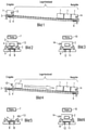
- Figure 1 shows a typical roller conveyor 3 of a flow rack for objects such as products, goods, containers, pallets, etc. 1 according to a first embodiment of the present invention.
- the objects 1 provided with an RFID transponder 2 are placed in the input and recorded.
- the input recognition is carried out either with or without a presence sensor 13 .
- the RFID antenna attached in the entrance area must be constantly in reading mode (polling) in order to register whether an RFID transponder 2 is in the detection range of the RFID antenna 5 attached to the entry area in a stationary manner.
- presence sensor 13 the RFID antenna 5 only has to read when the presence sensor reports a change and can thus save power.
- Presence sensors only determine whether an object with or without an RFID transponder is within their range.
- the object 1 is held by a holding device 4, e.g. a mechanical bolt or a magnet, until it can be identified using RFID.
- Figures 2 and 3 show examples of input and output feedback options.
- Feedback can be given on the input side, e.g. via an acoustic or optical signal (7, 8, 9). Feedback via another interface is also possible.
- a warning lamp 8 gives a corresponding signal, while the object in question is blocked by the holding device 4 .
- the indicator light 12 signals that the correctly stored items are ready for output. Additionally or alternatively, displays with appropriate information can be used on both the input and output side.
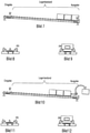
- Figure 4 shows another example of a typical roller conveyor 3 of a flow rack for items 1 in the event that an approved item has been entered. Since the item was identified as approved for the roller conveyor after reading its RFID transponder, the holding device releases the item, which now slides down the sloping roller conveyor into the stock in the direction of the output. If the test is negative, item 1 must be removed. If item 1 is allowed to enter, the stock in the flow rack is increased and recorded in the evaluation system.
- the storage management described is not limited to a flow rack, but rather groups of racks that include flow racks arranged next to one another or one on top of the other are conceivable. In this case, the stock levels of the individual flow racks are recorded centrally and booked accordingly.
- Figures 5 and 6 show examples of inbound and outbound feedback options when a correct item entry has been made.
- the feedback can be on the input or output side, e.g. via an acoustic or optical signal (7, 8, 9). Feedback via another interface such as an internal booking system is also possible. In this case, it may be possible to dispense with any system feedback.
- an indicator light 9 gives a corresponding signal while the approved item runs unhindered into the storage section.
- the indicator lamp 12 again signals that the correctly stored objects are ready for output.
- displays with appropriate information can be used on both the input and output sides.
- Figure 7 shows another example of a typical flow rack roller conveyor for items ready for dispensing after the front item has been registered as approved.
- Figures 8 and 9 show examples of input and output feedback options for the case of a successful storage process. After the transponder on the input side can no longer be read because the object has entered the storage section and has already passed the first RFID antenna in the input area, no status information is signaled and lights 8 or 9 are not lit.
- Figure 10 shows another example of a typical roller conveyor 3 of a flow rack for articles 1 in the event that an article is removed on the output side.
- the removal is now recognized analogously to the input situation in Figure 1 in that the RFID transponder 2 can no longer be read and/or the presence sensor 14 reports a change. Since at this point in time a subsequent article has not yet reached the effective range of the second RFID antenna 6 and therefore no further RFID transponder is read or a presence sensor reports a change, the inventory of the flow rack is reduced accordingly in the evaluation system.
- Figures 11 and 12 show examples of input and output feedback options for the storage process described in Figure 10. Since the article rolling in in this case has not yet been registered, the warning light 12 in Figure 12 indicates that it is not yet ready to be dispensed.
- Figure 13 shows a typical article storage line 1 according to a second embodiment of the present invention, with the difference that the storage line consists of a track for moving and storing trolleys therein, instead of a rack with roller tracks.
- the above-described exemplary embodiments of a first embodiment of the present invention are also applicable to this second embodiment of the present invention.
- the filling or removal of the objects 1 described in the above exemplary embodiments can also be forwarded to an ERP system as a booking message.
- the present invention is not limited to the exemplary embodiments shown, rather one or more features of one exemplary embodiment can also be used in another exemplary embodiment.
Description
Die vorliegende Erfindung beschreibt die automatische Bestandüberwachung von Durchlauflagern mittels eines Radiofrequenz-Identifikations-Kommunikationssystems (RFID-Kommunikationssystem).The present invention describes the automatic inventory monitoring of flow warehouses using a radio frequency identification (RFID) communication system.
Durchlauflager sind Lagereinrichtungen, die u. a. mittels geführter Rollwägen auf Durchlaufbahnen oder mittels Rollbahnen auf Durchlaufregalen mit Waren bestückt werden. Beim Einsatz von Durchlaufregalen werden die Regale von einer Seite aus bestückt, indem die Waren in Behältern oder auf Paletten auf die Rollbahnen der Durchlaufregale verbracht werden, während von der anderen Seite aus die vorher eingelagerten Waren wieder entnommen werden können. Im Unterschied zur Variante mit Durchlaufregalen werden die Waren bei Durchlaufbahnen auf Rollwagen in rollbaren Behältern oder auf rollbaren Paletten verschoben.Flow-through warehouses are storage facilities that e.g. loaded with goods by means of guided trolleys on flow conveyors or by means of roller conveyors on flow racks. When using flow racks, the racks are loaded from one side by bringing the goods in containers or on pallets onto the roller conveyors of the flow racks, while the previously stored goods can be removed from the other side. In contrast to the variant with flow racks, the goods on flow conveyors are moved on trolleys in rollable containers or on rollable pallets.
RFID-Kommunikationssysteme für Lagerlogistik umfassen in der Regel ein RFID-Gerät zum Auslesen und/oder Beschreiben eines Transponders, der an den Gegenständen, Produkten, Behältern bzw. Paletten angebracht ist. An das RFID-Gerät ist dafür eine Antenne elektrisch angeschlossen, die entweder fest in das RFID-Gerät integriert ist, oder als externes Gerät genutzt wird. Zur Kommunikation mit dem Transponder erzeugt die Antenne des RFID-Geräts ein elektromagnetisches Feld im Radiofrequenzbereich, das in einer Antenne des Transponders eine Spannung induziert. Dabei werden typischerweise folgende Frequenzbereiche und Reichweiten genutzt.
Damit können einerseits Daten zwischen dem RFID-Gerät und dem Transponder übertragen werden, andererseits wird dadurch der Transponder mit Energie versorgt. RFID -Kommunikationssysteme besitzen zahlreiche Anwendungsmöglichkeiten, wie z.B. automatische Datenerfassung oder automatische Objektidentifikation. Mögliche Einsatzgebiete sind dabei die Verkehrsüberwachung, Kontrolle von Produktionslogistik, die Identifizierung von Personen oder die Echtheitszertifizierung von Banknoten.On the one hand, this allows data to be transmitted between the RFID device and the transponder and, on the other hand, the transponder is supplied with energy. RFID communication systems have numerous possible applications, such as automatic data acquisition or automatic object identification. Possible areas of application are traffic surveillance, control of production logistics, identification of people or certification of banknote authenticity.
Gegenwärtige Lagerungssysteme nutzen RFID -Kommunikation, um an der Ausgabeseite von Durchlauflagern die Entnahme von Waren zu registrieren und damit den Warenbestand zu erfassen und zu kontrollieren. Hierzu werden die mit einem RFID-Transponder versehenen Waren beim Verlassen des Durchlauflagers an einem stationären RFID-Gerät mit Antenne vorbeigeführt, um die im Transponder gespeicherte Kennung auszulesen. Auf diese Weise wird der Warenausgang automatisch erfasst und in einem Logistiksystem entsprechend verbucht.Current storage systems use RFID communication to register the removal of goods at the output side of flow storage and thus record and control the inventory. For this purpose, the goods provided with an RFID transponder are guided past a stationary RFID device with an antenna when leaving the flow storage facility in order to read out the identifier stored in the transponder. In this way, the outgoing goods are automatically recorded and booked accordingly in a logistics system.
Der Nachteil des im Vorgang erläuterten Stands der Technik besteht allerdings darin, dass lediglich die Ausgabeseite mit einem RFID -Scanner bedient wird, während für die Eingabeseite kein RFID-Scanner vorgesehen ist. Da also beim Eingabeprocedere der Behälter oder die Palette keine Identifizierung stattfindet, kann nicht überprüft werden, ob der Behälter oder die Palette überhaupt für diese(s) Durchlaufregal oder - bahn vorgesehen ist. Es besteht daher das Risiko, dass der Lagerbestand mit Fehlstücken bestückt wird, die später mühsam aussortiert werden müssen und damit die Lagerlogistik erschweren.However, the disadvantage of the prior art explained in the process is that only the output side is operated with an RFID scanner, while no RFID scanner is provided for the input side. Since the container or pallet is not identified during the input procedure, it is not possible to check whether the container or pallet is actually intended for this flow rack or flow lane. There is therefore a risk that the inventory will be stocked with missing items that later have to be laboriously sorted out and thus make warehouse logistics more difficult.
Die Druckschrift
Die Druckschrift
Die Druckschrift
Es ist daher die Aufgabe der vorliegenden Erfindung, den Stand der Technik zu verbessern. Insbesondere ist es Aufgabe der vorliegenden Erfindung, eine automatische Bestandüberwachung eines Durchlauflagers mittels eines RFID- Kommunikationssystems bereitzustellen, das die Lagerverwaltung umfassend automatisiert und den Lagerbestand automatisch aktualisiert und optimiert.It is therefore the object of the present invention to improve the prior art. In particular, it is the object of the present invention to provide automatic inventory monitoring of a flow store using an RFID communication system, which comprehensively automates the warehouse management and automatically updates and optimizes the inventory.
Die Aufgabe wird durch ein Radiofrequenz-Identifikations-Kommunikationssystem, RFID-Kommunikationssystem, zur Bestandüberwachung eines Durchlauflagers gemäß Anspruch 1 gelöst.The task is carried out by a radio frequency identification communication system, RFID communication system, for inventory monitoring of a flow store according to
Das erfindungsgemäße RFID-Kommunikationssystem umfasst mindestens eine erste und eine zweite stationäre RFID-Antenne zum Senden und Empfangen von Daten und einen an einem Gegenstand oder einer Gruppe von Gegenständen angebrachten RFID-Transponder, wobei der RFID-Transponder mindestens eine Kennung des Gegenstands oder der Gruppe von Gegenständen elektronisch speichert, und wobei die erste RFID-Antenne an einem Eingabebereich und die zweite RFID-Antenne an einem Ausgabebereich einer Lagerstrecke des Durchlauflagers platziert sind, um den Gegenstand oder die Gruppe von Gegenständen anhand der Kennung des RFID-Transponders zu erfassen.The inventive RFID communication system comprises at least a first and a second stationary RFID antenna for sending and receiving data and an RFID transponder attached to an object or a group of objects, the RFID transponder having at least one identifier of the object or group electronically stores objects, and wherein the first RFID antenna is placed in an input area and the second RFID antenna is placed in an output area of a storage section of the flow warehouse in order to detect the object or the group of objects using the identifier of the RFID transponder.
Das erfindungsgemäße RFID-Kommunikationssystem ermöglicht es daher, dass Waren erfasst werden, bevor sie in den Lagerbestand aufgenommen werden. Dazu werden die mit einem RFID-Transponder versehenen Gegenstände, Produkte, Waren bzw. Behälter in die Eingabe gestellt und durch eine stationäre, eingangsseitige RFID-Antenne identifiziert, indem die in dem Transponder gespeicherten Identifizierungsdaten (Kennung) ausgelesen werden. Dadurch wird einerseits vermieden, dass falsche Artikel in den Lagerbestand aufgenommen werden und andererseits kann bei Entnahme von Artikeln eine automatische Nachbestellung erfolgen, da durch den Eingangsscan Informationen über den Lagerbestand in der jeweiligen Lagerstrecke vorliegen. Als Folge wird die Lagerlogistik entlastet und unnötige Bestellungen werden vermieden.The RFID communication system according to the invention therefore makes it possible for goods to be recorded before they are included in the inventory. For this purpose, the items, products, goods or containers provided with an RFID transponder are placed in the input and identified by a stationary, input-side RFID antenna by reading out the identification data (identification) stored in the transponder. On the one hand, this prevents incorrect items from being included in the inventory and, on the other hand, an automatic reordering can take place when items are removed, since the incoming scan provides information about the inventory in the respective storage section. As a result, the warehouse logistics are relieved and unnecessary orders are avoided.
Um den Bedürfnissen der jeweiligen Lagerlogistik zu entsprechen, sind die RFID-Antennen jederzeit demontierbar, um sie an geeigneter anderer Stelle im Lager wieder aufzubauen.In order to meet the needs of the respective warehouse logistics, the RFID antennas can be dismantled at any time in order to set them up again at a suitable location in the warehouse.
In einer ersten Ausführungsform besteht der Gegenstand oder die Gruppe von Gegenständen aus Behältern oder Paletten, wobei die Lagerstrecke aus einem Regal mit einer Rollbahn besteht, um die Behälter oder Paletten aufzunehmen.In a first embodiment, the item or group of items consists of containers or pallets, the storage line consisting of a rack with a runway to receive the containers or pallets.
In einer zweiten Ausführungsform besteht der Gegenstand oder die Gruppe von Gegenständen aus Rollwägen, wobei die Lagerstrecke aus einer Bahn besteht, um darin die Rollwägen zu verschieben und zu lagern.In a second embodiment, the item or group of items consists of trolleys, the storage line consisting of a track for moving and storing the trolleys therein.
Erfindungsgemäß umfasst das erfindungsgemäße RFID-Kommunikationssystem weiterhin mindestens einen Präsenzsensor, um die Präsenz eines Gegenstandes oder einer Gruppe von Gegenständen im Ein- und Ausgabebereich der Lagerstrecke zu erfassen.According to the invention, the RFID communication system according to the invention also includes at least one presence sensor in order to detect the presence of an object or a group of objects in the input and output area of the storage line.
Erfindungsgemäß sind ein erster Präsenzsensor am Eingabebereich und ein zweiter Präsenzsensor am Ausgabebereich der Lagerstrecke des Durchlauflagers platziert.According to the invention, a first presence sensor is placed in the input area and a second presence sensor is placed in the output area of the storage section of the flow store.
Weiterhin erfindungsgemäß wird der Lesemodus der RFID- Antennen zum Erfassen der RFID-Transponder nur dann aktiviert, wenn die Präsenzsensoren eine Änderung melden.Furthermore, according to the invention, the reading mode of the RFID antennas for detecting the RFID transponders is only activated when the presence sensors report a change.
Erfindungsgemäß werden der Gegenstand oder die Gruppe von Gegenständen im Eingabebereich durch eine Halteeinrichtung solange gehalten, bis diese mittels der Kennung des RFID-Transponders identifiziert sind.According to the invention, the object or the group of objects are held in the input area by a holding device until they are identified using the identifier of the RFID transponder.
Vorteilhafterweise sind der Gegenstand oder die Gruppe von Gegenständen anhand der Kennung des RFID-Transponders dahingehend prüfbar, ob der Gegenstand oder die Gruppe von Gegenständen für die Lagerstrecke zugelassen sind.The object or the group of objects can advantageously be checked using the identifier of the RFID transponder to determine whether the object or the group of objects are permitted for the storage section.
Weiterhin vorteilhafterweise kann die Halteeinrichtung den Gegenstand oder die Gruppe von Gegenständen je nach Ergebnis der Prüfung freigeben oder blockieren.Furthermore advantageously, the holding device can release or block the object or the group of objects depending on the result of the test.
Vorteilhafterweise wird ein Lagerbestand der Lagerstrecke erhöht, wenn die Halteeinrichtung den Gegenstand oder die Gruppe von Gegenständen freigibt.Advantageously, a stock of the storage line is increased when the holding device releases the object or the group of objects.
Vorteilhafterweise wird im Gegenzug der Lagerbestand der Lagerstrecke reduziert, wenn der Gegenstand oder die Gruppe von Gegenständen der Lagerstrecke nach Passieren der zweiten RFID-Antenne entnommen wird.In return, the stock in the storage section is advantageously reduced if the object or the group of objects is removed from the storage section after passing the second RFID antenna.
Vorteilhafterweise wird die Entnahme dadurch erkennbar, dass der RFID-Transponder nicht mehr lesbar ist und / oder der Präsenzsensor eine Änderung meldet.The removal is advantageously recognizable by the fact that the RFID transponder can no longer be read and/or the presence sensor reports a change.
Vorteilhafterweise kann die Halteeinrichtung aus einem mechanischen Bolzen oder einem Magneten bestehen.Advantageously, the holding device can consist of a mechanical bolt or a magnet.
Weiterhin vorteilhafterweise kann das RFID-Kommunikationssystem eine Rückmeldung erzeugen, wenn die erste RFID-Antenne den Gegenstand oder die Gruppe von Gegenständen identifiziert hat, wobei idealerweise eine Rückmeldung über ein akustisches oder optisches Signal erfolgt.Furthermore advantageously, the RFID communication system can generate feedback when the first RFID antenna has identified the object or the group of objects, with feedback ideally taking the form of an acoustic or optical signal.
Vorteilhafterweise kann das RFID-Kommunikationssystem eine Rückmeldung erzeugen, wenn die zweite RFID-Antenne den Gegenstand oder die Gruppe von Gegenständen identifiziert hat, wobei idealerweise eine Rückmeldung über ein akustisches oder optisches Signal erfolgt.Advantageously, the RFID communication system can generate feedback when the second RFID antenna has identified the object or the group of objects, with feedback ideally taking the form of an acoustic or optical signal.
Die vorliegende Erfindung wird im Folgenden anhand der zwei eingangs erwähnten bevorzugten Ausführungsformen in Bezug auf die beigefügten
Bild 1 zeigt die erste Ausführungsform der Erfindung als typische Rollenbahn eines Durchlaufregals für BehälterBild 2 zeigt verschiedene Beispiele für eingabeseitige RückmeldungsvorrichtungenBild 3 zeigt verschiedene Beispiele für ausgabeseitige RückmeldungsvorrichtungenBild 4 zeigt eine typische Rollenbahn eines Durchlaufregals für Behälter für den Fall, dass ein korrekter Behälter eingelegt wurde.Bild 5 zeigt verschiedene Beispiele für eingabeseitige Rückmeldungsvorrichtungen für den Fall, dass ein korrekter Behälter eingelegt wurde.Bild 6 zeigt verschiedene Beispiele für ausgabeseitige Rückmeldungsvorrichtungen für den Fall, dass ein korrekter Behälter eingelegt wurde.Bild 7 zeigt eine typische Rollenbahn eines Durchlaufregals für Behälter, die bereit zur Ausgabe sind, nachdem der vorderste Artikel registriert wurde.Bild 8 zeigt verschiedene Beispiele für eingabeseitige Rückmeldungsvorrichtungen für den Fall, dass die Behälter im Lagerbestand bereit zur Ausgabe sind.Bild 9 zeigt verschiedene Beispiele für ausgabeseitige Rückmeldungsvorrichtungen für den Fall, dass die Behälter im Lagerbestand bereit zur Ausgabe sind.Bild 10 zeigt eine typische Rollenbahn eines Durchlaufregals für Behälter, die nicht bereit zur Ausgabe sind, nachdem der vorderste Artikel nicht registriert wurde.Bild 11 zeigt verschiedene Beispiele für eingabeseitige Rückmeldungsvorrichtungen für den Fall, dass der vorderste Behälter im Lagerbestand nicht bereit zur Ausgabe ist.Bild 12 zeigt verschiedene Beispiele für ausgabeseitige Rückmeldungsvorrichtungen für den Fall, dass der vorderste Behälter im Lagerbestand nicht bereit zur Ausgabe ist.Bild 13 zeigt eine zweite Ausführungsform der Erfindung, wobei die Waren in Rollwägen statt als Container auf Rollbahnen in die Lagerstrecke eingebracht werden.
- Figure 1 shows the first embodiment of the invention as a typical roller conveyor of a flow rack for containers
- Figure 2 shows various examples of input-side feedback devices
- Figure 3 shows various examples of output-side feedback devices
- Figure 4 shows a typical roller conveyor of a tote flow rack if a correct tote has been inserted.
- Figure 5 shows various examples of input-side feedback devices in the event that a correct container has been inserted.
- Figure 6 shows various examples of output-side feedback devices in the event that a correct tray has been inserted.
- Figure 7 shows a typical flow rack roller conveyor for cases ready for dispensing after the foremost item has been registered.
- Figure 8 shows various examples of input-side feedback devices when the bins in stock are ready for dispensing.
- Figure 9 shows various examples of output-side feedback devices when the bins in stock are ready for output.
- Figure 10 shows a typical flow rack roller conveyor for cases that are not ready for dispensing after the front item has not been registered.
- Figure 11 shows various examples of input-side feedback devices when the foremost bin in the inventory is not ready for dispensing.
- Figure 12 shows various examples of dispenser-side feedback devices when the foremost bin in inventory is not ready for dispenser.
- Figure 13 shows a second embodiment of the invention, in which the goods are brought into the storage section in trolleys instead of as containers on roller tracks.
Bild 1 zeigt eine typische Rollenbahn 3 eines Durchlaufregals für Gegenstände wie Produkte, Waren, Behälter, Paletten etc. 1 gemäß einer ersten Ausführungsform der vorliegenden Erfindung. Die mit einem RFID-Transponder 2 versehenen Gegenstände 1 werden in die Eingabe gestellt und erfasst. Die Eingabeerkennung wird entweder mit oder ohne einen Präsenzsensor 13 durchgeführt. Ohne Präsenzsensor muss sich die im Eingangsbereich angebrachte RFID-Antenne ständig im Lesebetrieb (polling) befinden, um zu registrieren, ob sich ein RFID-Transponder 2 im Erkennungsbereich der stationär am Eingabebereich angebrachten RFID-Antenne 5 befindet. Mit Präsenzsensor 13 muss die RFID-Antenne 5 nur lesen, wenn der Präsenzsensor eine Änderung meldet und kann damit Strom sparen. Präsenzsensoren ermitteln dabei lediglich, ob sich ein Gegenstand mit oder ohne RFID-Transponder in ihrer Reichweite befindet. Der Gegenstand 1 wird durch eine Halteeinrichtung 4, z.B. ein mechanischer Bolzen oder ein Magnet, solange gehalten bis dieser mittels RFID identifiziert werden konnte.Figure 1 shows a
Bild 2 und 3 zeigen Beispiele für ein- und ausgangsseitige Rückmeldungsoptionen. Die Rückmeldung kann eingangsseitig z.B. über ein akustisches oder optisches Signal (7, 8, 9) erfolgen. Auch eine Rückmeldung über eine andere Schnittstelle ist möglich. Im Falle der versuchten Eingabe eines nicht zugelassenen Gegenstandes 1 gibt eine Warnleuchte 8 ein entsprechendes Signal, während der beanstandete Gegenstand durch die Haltevorrichtung 4 blockiert wird. Ausgabeseitig signalisiert die Hinweisleuchte 12, dass die korrekt gelagerten Gegenstände zur Ausgabe bereit sind. Sowohl eingabewie auch ausgabeseitig können zusätzlich oder alternativ Displays mit entsprechenden Hinweisen zum Einsatz kommen.Figures 2 and 3 show examples of input and output feedback options. Feedback can be given on the input side, e.g. via an acoustic or optical signal (7, 8, 9). Feedback via another interface is also possible. If an
Bild 4 zeigt ein weiteres Beispiel einer typischen Rollenbahn 3 eines Durchlaufregals für Gegenstände 1 für den Fall, dass ein zugelassener Gegenstand eingegeben wurde. Da der Gegenstand nach dem Lesen seines RFID-Transponders als für die Rollenbahn zugelassen identifiziert wurde, gibt die Haltevorrichtung den Gegenstand frei, der nun auf der abschüssigen Rollenbahn in den Lagerbestand in Richtung Ausgabe gleitet. Fällt die Prüfung negativ aus, muss der Gegenstand 1 entfernt werden. Darf der Gegenstand 1 einfahren, wird der Lagerbestand des Durchlaufregals erhöht und im Auswertesystem erfasst. Im Übrigen ist die beschriebene Lagerverwaltung nicht auf ein Durchlaufregal beschränkt, sondern Gruppen von Regalen, die nebeneinander oder übereinander angeordnete Durchlaufregale umfassen, sind denkbar. In diesem Fall werden die Lagerbestände der einzelnen Durchlaufregale zentral erfasst und entsprechend verbucht.Figure 4 shows another example of a
Bild 5 und 6 zeigen Beispiele für ein- und ausgangsseitige Rückmeldungsoptionen für den Fall, dass eine richtige Artikeleingabe erfolgt ist. Die Rückmeldung kann eingangs- wie auch ausgangsseitig z.B. über ein akustisches oder optisches Signal (7, 8, 9) erfolgen. Auch eine Rückmeldung über eine andere Schnittstelle wie etwa ein internes Buchungssystem ist möglich. In diesem Fall kann u. U. auf eine etwaige Systemrückmeldungen verzichtet werden. Im Falle der Eingabe eines zugelassenen Gegenstandes 1 gibt eine Hinweisleuchte 9 ein entsprechendes Signal, während der zugelassene Gegenstand ungehindert in die Lagerstrecke läuft. Ausgabeseitig signalisiert wieder die Hinweisleuchte 12, dass die korrekt gelagerten Gegenstände zur Ausgabe bereit sind. Sowohl eingabe- wie auch ausgabeseitig können wieder zusätzlich oder alternativ Displays mit entsprechenden Hinweisen zum Einsatz kommen.Figures 5 and 6 show examples of inbound and outbound feedback options when a correct item entry has been made. The feedback can be on the input or output side, e.g. via an acoustic or optical signal (7, 8, 9). Feedback via another interface such as an internal booking system is also possible. In this case, it may be possible to dispense with any system feedback. If an approved
Bild 7 zeigt ein weiteres Beispiel einer typischen Rollenbahn eines Durchlaufregals für Gegenstände, die bereit zur Ausgabe sind, nachdem der vorderste Artikel als zugelassen registriert wurde.Figure 7 shows another example of a typical flow rack roller conveyor for items ready for dispensing after the front item has been registered as approved.
Bild 8 und 9 zeigen wiederum Beispiele für ein- und ausgangsseitige Rückmeldungsoptionen für den Fall eines erfolgreichen Lagerungsvorgangs. Nachdem der Transponder eingangsseitig nicht mehr gelesen werden kann, da der Gegenstand in die Lagerstrecke eingefahren und die erste RFID-Antenne im Eingangsbereich bereits passiert hat, werden auch keine Statushinweise signalisiert und die Leuchten 8 bzw. 9 sind nicht erleuchtet. Die Hinweisleuchte 12 in Bild 9 dagegen signalisiert ausgabeseitig, dass die korrekt gelagerten Gegenstände zur Ausgabe bereit sind.Figures 8 and 9 show examples of input and output feedback options for the case of a successful storage process. After the transponder on the input side can no longer be read because the object has entered the storage section and has already passed the first RFID antenna in the input area, no status information is signaled and
Bild 10 zeigt ein weiteres Beispiel einer typischen Rollenbahn 3 eines Durchlaufregals für Gegenstände 1 für den Fall, dass ein Artikel auf der Ausgabeseite entnommen wird. Die Entnahme wird nun analog zur Eingabe-Situation in Bild 1 dadurch erkannt, dass der RFID-Transponder 2 nicht mehr gelesen werden kann und /oder der Präsenzsensor 14 eine Änderung meldet. Da zu diesem Zeitpunkt ein darauf folgender Artikel den Wirkbereich der zweiten RFID-Antenne 6 noch nicht erreicht hat und damit kein weiterer RFID-Transponder gelesen wird oder ein Präsenzsensor eine Änderung meldet, wird der Lagerbestand des Durchlaufregals im Auswertesystem entsprechend reduziert.Figure 10 shows another example of a
Bild 11 und 12 zeigen Beispiele für ein- und ausgangsseitige Rückmeldungsoptionen für den im Bild 10 beschriebenen Lagerungsvorgangs. Da der in diesem Fall anrollende Artikel noch nicht registriert ist, signalisiert die Warnleuchte 12 in Bild 12, dass noch keine Ausgabebereitschaft vorliegt.Figures 11 and 12 show examples of input and output feedback options for the storage process described in Figure 10. Since the article rolling in in this case has not yet been registered, the
Bild 13 zeigt eine typische Lagerstrecke für Gegenstände 1 gemäß einer zweiten Ausführungsform der vorliegenden Erfindung, mit dem Unterschied, dass die Lagerstrecke statt aus einem Regal mit Rollbahnen aus einer Bahn besteht, um darin Rollwägen zu verschieben und zu lagern. Die oben beschriebenen Ausführungsbeispiele einer ersten Ausführungsform der vorliegenden Erfindung sind auch anwendbar für diese zweite Ausführungsform der vorliegenden Erfindung.Figure 13 shows a typical
Generell kann das in den obigen Ausführungsbeispielen beschriebene Befüllen oder Entnehmen der Gegenstände 1 auch als Buchungsmeldung an ein ERP-System weitergegeben werden.In general, the filling or removal of the
Die vorliegende Erfindung ist nicht auf die dargestellten Ausführungsbeispiele beschränkt, vielmehr können ein oder mehrere Merkmale eines Ausführungsbeispiels auch in einem anderen Ausführungsbeispiel verwendet werden.The present invention is not limited to the exemplary embodiments shown, rather one or more features of one exemplary embodiment can also be used in another exemplary embodiment.
Claims (16)
- A radio frequency identification communication system, RFID communication system, for inventory monitoring of a flow-through warehouse, comprising:at least a first and a second stationary RFID antenna (5, 6) for transmitting and receiving data; anda RFID transponder (2) attached to an object or group of objects (1),wherein the RFID transponder (2) electronically stores at least one identifier of the object or group of objects (1), andwherein the first RFID antenna (5) is placed at an input area and the second RFID antenna (6) is placed at an output area of a storage section of the flow-through warehouse to detect the object or group of objects (1) based on the identification of the RFID transponder (2), andat least one presence sensor (13, 14) for detecting the presence of an object or a group of objects in the input and output area of the storage section, wherein a first presence sensor (13) is placed at the input area and a second presence sensor (14) is placed at the output area (6) of the storage section of the flow-through warehouse wherein the at least one presence sensor only determines whether an object with or without an RFID transponder is within its range, wherein the RFID antennas (5, 6) only activate a read mode for detecting the RFID transponders when the presence sensors (13, 14) report a change,wherein the object or group of objects (1) is held in the input area by a holding device (4) until it is identified by means of the identifier of the RFID transponder (2).
- RFID communication system according to claim 1, wherein the object or group of objects consists of containers or pallets (1).
- RFID communication system according to claim 2, wherein the storage section consists of a rack with a roller conveyor to receive the containers or pallets (1).
- RFID communication system according to claim 1, wherein the object or group of objects rests on rolling carts.
- RFID communication system according to claim 4, wherein the storage section consists of a track to move and store the rolling carts therein.
- RFID communication system according to claim 1, wherein the object or group of objects (1) is checkable by the identifier of the RFID transponder (2) as to whether the object or group of objects is approved for the storage section.
- RFID communication system according to claim 6, wherein the holding device releases or blocks the object or group of objects (1) depending on the result of the check.
- RFID communication system of claim 7, wherein an inventory of the storage section is increased when the holding device releases the object or group of objects.
- RFID communication system of claim 8, wherein the inventory of the storage section is reduced when the object or group of objects is removed from the storage section after passing the second RFID antenna.
- RFID communication system according to claim 9, wherein the removal is detectable by the RFID transponder (2) no longer being readable and/or the presence sensor reporting a change.
- RFID communication system according to any one of claims 1 to 10, wherein the holding device (4) comprises a mechanical bolt.
- RFID communication system according to any one of claims 1 to 10, wherein the holding device (4) comprises a magnet.
- RFID communication system of claim 1, wherein the system generates feedback when the first RFID antenna has identified the object or group of objects.
- RFID communication system according to claim 13, wherein the feedback is provided via an acoustic or optical signal (7, 8, 9).
- RFID communication system of claim 1, wherein the system generates a feedback when the second RFID antenna has identified the object or group of objects prior to removal.
- RFID communication system according to claim 15, wherein the feedback is provided via an acoustic or optical signal (10, 11, 12).
Applications Claiming Priority (2)
| Application Number | Priority Date | Filing Date | Title |
|---|---|---|---|
| DE102010029996.0A DE102010029996B4 (en) | 2010-06-11 | 2010-06-11 | Inventory monitoring of flow warehouses using RFID |
| PCT/EP2011/057690 WO2011154213A1 (en) | 2010-06-11 | 2011-05-12 | Monitoring the stock in dynamic stores using rfid |
Publications (3)
| Publication Number | Publication Date |
|---|---|
| EP2580716A1 EP2580716A1 (en) | 2013-04-17 |
| EP2580716B1 EP2580716B1 (en) | 2019-03-27 |
| EP2580716B2 true EP2580716B2 (en) | 2022-01-19 |
Family
ID=44119046
Family Applications (1)
| Application Number | Title | Priority Date | Filing Date |
|---|---|---|---|
| EP11721276.1A Active EP2580716B2 (en) | 2010-06-11 | 2011-05-12 | Monitoring the stock in flow racks using rfid |
Country Status (4)
| Country | Link |
|---|---|
| US (1) | US8955748B2 (en) |
| EP (1) | EP2580716B2 (en) |
| DE (1) | DE102010029996B4 (en) |
| WO (1) | WO2011154213A1 (en) |
Families Citing this family (6)
| Publication number | Priority date | Publication date | Assignee | Title |
|---|---|---|---|---|
| EP3276552A1 (en) | 2016-07-26 | 2018-01-31 | Intellion AG | Rfid communication system for electronic stock monitoring of a flow rack |
| AT519745B1 (en) * | 2017-06-06 | 2018-10-15 | Knapp Ag | RFID picking station |
| CN112209124A (en) * | 2019-07-10 | 2021-01-12 | 北京京东振世信息技术有限公司 | Loading and unloading mechanism, loading and unloading equipment, loading and unloading method, storage medium and electronic equipment |
| DE102019131560A1 (en) * | 2019-11-22 | 2021-05-27 | Dirk Bloksma | Storage station with several storage units for receiving articles to be stored |
| DE102020006599B4 (en) | 2020-10-27 | 2023-06-07 | ORGATEX GmbH | Method and device for monitoring and controlling a FIFO station |
| DE102022107824A1 (en) | 2022-04-01 | 2023-10-05 | ORGATEX GmbH | Method for controlling and monitoring an intralogistics process |
Citations (1)
| Publication number | Priority date | Publication date | Assignee | Title |
|---|---|---|---|---|
| WO2009152139A1 (en) † | 2008-06-11 | 2009-12-17 | Symbol Technologies, Inc. | Methods and systems for rfid reader power management |
Family Cites Families (14)
| Publication number | Priority date | Publication date | Assignee | Title |
|---|---|---|---|---|
| DE29710367U1 (en) * | 1997-04-10 | 1997-09-25 | Leeners Martin | Device for storing units of goods |
| DE19714799C2 (en) * | 1997-04-10 | 2001-08-02 | Kristian Dicke | Device for storing units of goods |
| US6150948A (en) | 1999-04-24 | 2000-11-21 | Soundcraft, Inc. | Low-power radio frequency identification reader |
| JP4140136B2 (en) * | 1999-07-08 | 2008-08-27 | 富士通株式会社 | Inventory management device |
| EP1695202A4 (en) * | 2003-11-25 | 2008-05-14 | Us Postal Service | Methods and systems for tracking delivery items |
| EP1855938B1 (en) * | 2005-01-07 | 2010-09-15 | Siemens Industry, Inc. | Automated storage and retrieval system |
| FR2885435B1 (en) * | 2005-03-21 | 2007-07-20 | A Sis Soc Par Actions Simplifi | INSTALLATION FOR MANAGING TRACEABILITY AND CONTROL PREPARATION |
| US7295118B2 (en) | 2005-08-19 | 2007-11-13 | Ensyc Technologies | Low cost RFID system |
| US7602288B2 (en) * | 2005-12-01 | 2009-10-13 | Frito-Lay North America, Inc. | Method for slap-and-ship RFID labeling |
| US7576657B2 (en) | 2006-03-22 | 2009-08-18 | Symbol Technologies, Inc. | Single frequency low power RFID device |
| US7940181B2 (en) * | 2007-02-01 | 2011-05-10 | Infosys Technologies Ltd. | RFID based product level availability |
| DE202007009056U1 (en) * | 2007-06-27 | 2007-10-25 | Robert Bosch Gmbh | Material warehouse with RFID antenna |
| DE202007017802U1 (en) | 2007-09-28 | 2008-03-06 | Atg Automatisierungstechnik Gera Gmbh | Electronic access control system |
| DE102008035633B4 (en) * | 2008-05-26 | 2013-09-26 | Karlsruher Institut für Technologie | A shelf assembly |
-
2010
- 2010-06-11 DE DE102010029996.0A patent/DE102010029996B4/en not_active Revoked
-
2011
- 2011-05-12 US US13/703,234 patent/US8955748B2/en active Active
- 2011-05-12 EP EP11721276.1A patent/EP2580716B2/en active Active
- 2011-05-12 WO PCT/EP2011/057690 patent/WO2011154213A1/en active Application Filing
Patent Citations (1)
| Publication number | Priority date | Publication date | Assignee | Title |
|---|---|---|---|---|
| WO2009152139A1 (en) † | 2008-06-11 | 2009-12-17 | Symbol Technologies, Inc. | Methods and systems for rfid reader power management |
Also Published As
| Publication number | Publication date |
|---|---|
| EP2580716A1 (en) | 2013-04-17 |
| DE102010029996B4 (en) | 2021-08-05 |
| WO2011154213A1 (en) | 2011-12-15 |
| DE102010029996A1 (en) | 2011-12-15 |
| US8955748B2 (en) | 2015-02-17 |
| US20130075470A1 (en) | 2013-03-28 |
| EP2580716B1 (en) | 2019-03-27 |
Similar Documents
| Publication | Publication Date | Title |
|---|---|---|
| EP2580716B2 (en) | Monitoring the stock in flow racks using rfid | |
| EP2668118B1 (en) | Device and method for carrying out the inventory of a warehouse, and use of a computer programm product in such warehouse | |
| EP2937279A1 (en) | Freight loading system for loading and unloading of an item of freight, method for creating and/or updating a loading plan | |
| DE102006047797A1 (en) | Locker system for setting and picking up objects and method for operating the locker system | |
| DE10342767A1 (en) | Transponder-supported positioning system | |
| DE102008027646A1 (en) | System for automatic controlling of storing and/or commissioning of article e.g. pharmaceutical article, in shelf warehouse, has data-processing system generating control signals for controlling warehouse | |
| EP3291144A1 (en) | Rfid device and method for detecting compartment occupation | |
| DE102006052708B3 (en) | Arrangement and method for data acquisition | |
| EP2500850B1 (en) | Method and system for monitoring objects | |
| DE3711237A1 (en) | Method and apparatus for controlling piece goods conveying installations with the aid of transponders | |
| DE102011003027A1 (en) | System and method for storage and monitoring of goods using RFID technology | |
| EP1739516A1 (en) | System and method for surveying the transfer of goods provided with identification carriers | |
| DE202005005915U1 (en) | Return unit for deposit items, e.g. drinks cans and bottles has an arrangement for imaging a deposit label and an additional optical imaging system for detecting other information relating to the container and its origin | |
| DE10102999A1 (en) | Storing articles, especially pharmaceuticals, on shelves comprises passing them through identification unit where its dimensions are measured and code is applied, loading unit then moving them to suitable space on shelves | |
| EP2390204A2 (en) | System for completing a warehouse for small articles | |
| EP2835326B1 (en) | Picking system equiped with connectable storing modules, access detection and position sensors | |
| EP2415002A1 (en) | System for logistical monitoring and control of the flow of goods, the storage thereof, storage and transport conditions, and consumption | |
| DE102004035819B4 (en) | Method for automatic stock-taking in a warehouse | |
| EP2538377A2 (en) | Method for handling Kanban jobs and RFID pallet box | |
| EP1544830A1 (en) | A method and an apparatus for tracking objects | |
| DE202016106535U1 (en) | Material part storage system | |
| DE102006022526A1 (en) | Radio frequency identification system for seizing transponders afflicted articles, which are electronically registered in data bases and evaluated, involves detecting recovery rate and consignment status of raw materials | |
| EP3273382B1 (en) | Rfid reading device and method for compartment occupancy detection in a shelf | |
| EP3577428B1 (en) | Storage system comprising a detection arrangement assigned to the storage area | |
| EP3276552A1 (en) | Rfid communication system for electronic stock monitoring of a flow rack |
Legal Events
| Date | Code | Title | Description |
|---|---|---|---|
| PUAI | Public reference made under article 153(3) epc to a published international application that has entered the european phase |
Free format text: ORIGINAL CODE: 0009012 |
|
| 17P | Request for examination filed |
Effective date: 20121113 |
|
| AK | Designated contracting states |
Kind code of ref document: A1 Designated state(s): AL AT BE BG CH CY CZ DE DK EE ES FI FR GB GR HR HU IE IS IT LI LT LU LV MC MK MT NL NO PL PT RO RS SE SI SK SM TR |
|
| DAX | Request for extension of the european patent (deleted) | ||
| STAA | Information on the status of an ep patent application or granted ep patent |
Free format text: STATUS: EXAMINATION IS IN PROGRESS |
|
| 17Q | First examination report despatched |
Effective date: 20161208 |
|
| REG | Reference to a national code |
Ref country code: DE Ref legal event code: R079 Ref document number: 502011015535 Country of ref document: DE Free format text: PREVIOUS MAIN CLASS: G06Q0010000000 Ipc: G07F0011020000 |
|
| GRAP | Despatch of communication of intention to grant a patent |
Free format text: ORIGINAL CODE: EPIDOSNIGR1 |
|
| STAA | Information on the status of an ep patent application or granted ep patent |
Free format text: STATUS: GRANT OF PATENT IS INTENDED |
|
| RIC1 | Information provided on ipc code assigned before grant |
Ipc: G07F 11/02 20060101AFI20180907BHEP Ipc: G06K 7/01 20060101ALI20180907BHEP Ipc: G06Q 10/08 20120101ALI20180907BHEP |
|
| INTG | Intention to grant announced |
Effective date: 20181004 |
|
| GRAS | Grant fee paid |
Free format text: ORIGINAL CODE: EPIDOSNIGR3 |
|
| GRAA | (expected) grant |
Free format text: ORIGINAL CODE: 0009210 |
|
| STAA | Information on the status of an ep patent application or granted ep patent |
Free format text: STATUS: THE PATENT HAS BEEN GRANTED |
|
| AK | Designated contracting states |
Kind code of ref document: B1 Designated state(s): AL AT BE BG CH CY CZ DE DK EE ES FI FR GB GR HR HU IE IS IT LI LT LU LV MC MK MT NL NO PL PT RO RS SE SI SK SM TR |
|
| REG | Reference to a national code |
Ref country code: GB Ref legal event code: FG4D Free format text: NOT ENGLISH |
|
| REG | Reference to a national code |
Ref country code: CH Ref legal event code: EP |
|
| REG | Reference to a national code |
Ref country code: DE Ref legal event code: R096 Ref document number: 502011015535 Country of ref document: DE |
|
| REG | Reference to a national code |
Ref country code: AT Ref legal event code: REF Ref document number: 1113969 Country of ref document: AT Kind code of ref document: T Effective date: 20190415 |
|
| REG | Reference to a national code |
Ref country code: IE Ref legal event code: FG4D Free format text: LANGUAGE OF EP DOCUMENT: GERMAN |
|
| PG25 | Lapsed in a contracting state [announced via postgrant information from national office to epo] |
Ref country code: LT Free format text: LAPSE BECAUSE OF FAILURE TO SUBMIT A TRANSLATION OF THE DESCRIPTION OR TO PAY THE FEE WITHIN THE PRESCRIBED TIME-LIMIT Effective date: 20190327 Ref country code: FI Free format text: LAPSE BECAUSE OF FAILURE TO SUBMIT A TRANSLATION OF THE DESCRIPTION OR TO PAY THE FEE WITHIN THE PRESCRIBED TIME-LIMIT Effective date: 20190327 Ref country code: SE Free format text: LAPSE BECAUSE OF FAILURE TO SUBMIT A TRANSLATION OF THE DESCRIPTION OR TO PAY THE FEE WITHIN THE PRESCRIBED TIME-LIMIT Effective date: 20190327 Ref country code: NO Free format text: LAPSE BECAUSE OF FAILURE TO SUBMIT A TRANSLATION OF THE DESCRIPTION OR TO PAY THE FEE WITHIN THE PRESCRIBED TIME-LIMIT Effective date: 20190627 |
|
| REG | Reference to a national code |
Ref country code: NL Ref legal event code: MP Effective date: 20190327 |
|
| PG25 | Lapsed in a contracting state [announced via postgrant information from national office to epo] |
Ref country code: BG Free format text: LAPSE BECAUSE OF FAILURE TO SUBMIT A TRANSLATION OF THE DESCRIPTION OR TO PAY THE FEE WITHIN THE PRESCRIBED TIME-LIMIT Effective date: 20190627 Ref country code: RS Free format text: LAPSE BECAUSE OF FAILURE TO SUBMIT A TRANSLATION OF THE DESCRIPTION OR TO PAY THE FEE WITHIN THE PRESCRIBED TIME-LIMIT Effective date: 20190327 Ref country code: LV Free format text: LAPSE BECAUSE OF FAILURE TO SUBMIT A TRANSLATION OF THE DESCRIPTION OR TO PAY THE FEE WITHIN THE PRESCRIBED TIME-LIMIT Effective date: 20190327 Ref country code: HR Free format text: LAPSE BECAUSE OF FAILURE TO SUBMIT A TRANSLATION OF THE DESCRIPTION OR TO PAY THE FEE WITHIN THE PRESCRIBED TIME-LIMIT Effective date: 20190327 Ref country code: GR Free format text: LAPSE BECAUSE OF FAILURE TO SUBMIT A TRANSLATION OF THE DESCRIPTION OR TO PAY THE FEE WITHIN THE PRESCRIBED TIME-LIMIT Effective date: 20190628 Ref country code: NL Free format text: LAPSE BECAUSE OF FAILURE TO SUBMIT A TRANSLATION OF THE DESCRIPTION OR TO PAY THE FEE WITHIN THE PRESCRIBED TIME-LIMIT Effective date: 20190327 |
|
| PG25 | Lapsed in a contracting state [announced via postgrant information from national office to epo] |
Ref country code: SK Free format text: LAPSE BECAUSE OF FAILURE TO SUBMIT A TRANSLATION OF THE DESCRIPTION OR TO PAY THE FEE WITHIN THE PRESCRIBED TIME-LIMIT Effective date: 20190327 Ref country code: IT Free format text: LAPSE BECAUSE OF FAILURE TO SUBMIT A TRANSLATION OF THE DESCRIPTION OR TO PAY THE FEE WITHIN THE PRESCRIBED TIME-LIMIT Effective date: 20190327 Ref country code: EE Free format text: LAPSE BECAUSE OF FAILURE TO SUBMIT A TRANSLATION OF THE DESCRIPTION OR TO PAY THE FEE WITHIN THE PRESCRIBED TIME-LIMIT Effective date: 20190327 Ref country code: RO Free format text: LAPSE BECAUSE OF FAILURE TO SUBMIT A TRANSLATION OF THE DESCRIPTION OR TO PAY THE FEE WITHIN THE PRESCRIBED TIME-LIMIT Effective date: 20190327 Ref country code: CZ Free format text: LAPSE BECAUSE OF FAILURE TO SUBMIT A TRANSLATION OF THE DESCRIPTION OR TO PAY THE FEE WITHIN THE PRESCRIBED TIME-LIMIT Effective date: 20190327 Ref country code: ES Free format text: LAPSE BECAUSE OF FAILURE TO SUBMIT A TRANSLATION OF THE DESCRIPTION OR TO PAY THE FEE WITHIN THE PRESCRIBED TIME-LIMIT Effective date: 20190327 Ref country code: AL Free format text: LAPSE BECAUSE OF FAILURE TO SUBMIT A TRANSLATION OF THE DESCRIPTION OR TO PAY THE FEE WITHIN THE PRESCRIBED TIME-LIMIT Effective date: 20190327 Ref country code: PT Free format text: LAPSE BECAUSE OF FAILURE TO SUBMIT A TRANSLATION OF THE DESCRIPTION OR TO PAY THE FEE WITHIN THE PRESCRIBED TIME-LIMIT Effective date: 20190727 |
|
| PG25 | Lapsed in a contracting state [announced via postgrant information from national office to epo] |
Ref country code: PL Free format text: LAPSE BECAUSE OF FAILURE TO SUBMIT A TRANSLATION OF THE DESCRIPTION OR TO PAY THE FEE WITHIN THE PRESCRIBED TIME-LIMIT Effective date: 20190327 Ref country code: SM Free format text: LAPSE BECAUSE OF FAILURE TO SUBMIT A TRANSLATION OF THE DESCRIPTION OR TO PAY THE FEE WITHIN THE PRESCRIBED TIME-LIMIT Effective date: 20190327 |
|
| REG | Reference to a national code |
Ref country code: DE Ref legal event code: R026 Ref document number: 502011015535 Country of ref document: DE |
|
| REG | Reference to a national code |
Ref country code: CH Ref legal event code: PL |
|
| PG25 | Lapsed in a contracting state [announced via postgrant information from national office to epo] |
Ref country code: IS Free format text: LAPSE BECAUSE OF FAILURE TO SUBMIT A TRANSLATION OF THE DESCRIPTION OR TO PAY THE FEE WITHIN THE PRESCRIBED TIME-LIMIT Effective date: 20190727 |
|
| PLBI | Opposition filed |
Free format text: ORIGINAL CODE: 0009260 |
|
| PLAX | Notice of opposition and request to file observation + time limit sent |
Free format text: ORIGINAL CODE: EPIDOSNOBS2 |
|
| PG25 | Lapsed in a contracting state [announced via postgrant information from national office to epo] |
Ref country code: LI Free format text: LAPSE BECAUSE OF NON-PAYMENT OF DUE FEES Effective date: 20190531 Ref country code: MC Free format text: LAPSE BECAUSE OF FAILURE TO SUBMIT A TRANSLATION OF THE DESCRIPTION OR TO PAY THE FEE WITHIN THE PRESCRIBED TIME-LIMIT Effective date: 20190327 Ref country code: CH Free format text: LAPSE BECAUSE OF NON-PAYMENT OF DUE FEES Effective date: 20190531 Ref country code: DK Free format text: LAPSE BECAUSE OF FAILURE TO SUBMIT A TRANSLATION OF THE DESCRIPTION OR TO PAY THE FEE WITHIN THE PRESCRIBED TIME-LIMIT Effective date: 20190327 |
|
| 26 | Opposition filed |
Opponent name: BROECHER, DIRK JOACHIM Effective date: 20191223 |
|
| REG | Reference to a national code |
Ref country code: BE Ref legal event code: MM Effective date: 20190531 |
|
| GBPC | Gb: european patent ceased through non-payment of renewal fee |
Effective date: 20190627 |
|
| PG25 | Lapsed in a contracting state [announced via postgrant information from national office to epo] |
Ref country code: SI Free format text: LAPSE BECAUSE OF FAILURE TO SUBMIT A TRANSLATION OF THE DESCRIPTION OR TO PAY THE FEE WITHIN THE PRESCRIBED TIME-LIMIT Effective date: 20190327 Ref country code: LU Free format text: LAPSE BECAUSE OF NON-PAYMENT OF DUE FEES Effective date: 20190512 |
|
| PG25 | Lapsed in a contracting state [announced via postgrant information from national office to epo] |
Ref country code: TR Free format text: LAPSE BECAUSE OF FAILURE TO SUBMIT A TRANSLATION OF THE DESCRIPTION OR TO PAY THE FEE WITHIN THE PRESCRIBED TIME-LIMIT Effective date: 20190327 |
|
| PG25 | Lapsed in a contracting state [announced via postgrant information from national office to epo] |
Ref country code: IE Free format text: LAPSE BECAUSE OF NON-PAYMENT OF DUE FEES Effective date: 20190512 Ref country code: GB Free format text: LAPSE BECAUSE OF NON-PAYMENT OF DUE FEES Effective date: 20190627 |
|
| PLBB | Reply of patent proprietor to notice(s) of opposition received |
Free format text: ORIGINAL CODE: EPIDOSNOBS3 |
|
| PG25 | Lapsed in a contracting state [announced via postgrant information from national office to epo] |
Ref country code: BE Free format text: LAPSE BECAUSE OF NON-PAYMENT OF DUE FEES Effective date: 20190531 |
|
| PG25 | Lapsed in a contracting state [announced via postgrant information from national office to epo] |
Ref country code: FR Free format text: LAPSE BECAUSE OF NON-PAYMENT OF DUE FEES Effective date: 20190527 |
|
| REG | Reference to a national code |
Ref country code: AT Ref legal event code: MM01 Ref document number: 1113969 Country of ref document: AT Kind code of ref document: T Effective date: 20190512 |
|
| PG25 | Lapsed in a contracting state [announced via postgrant information from national office to epo] |
Ref country code: AT Free format text: LAPSE BECAUSE OF NON-PAYMENT OF DUE FEES Effective date: 20190512 |
|
| REG | Reference to a national code |
Ref country code: DE Ref legal event code: R082 Ref document number: 502011015535 Country of ref document: DE Representative=s name: DEHNSGERMANY PARTNERSCHAFT VON PATENTANWAELTEN, DE |
|
| PG25 | Lapsed in a contracting state [announced via postgrant information from national office to epo] |
Ref country code: CY Free format text: LAPSE BECAUSE OF FAILURE TO SUBMIT A TRANSLATION OF THE DESCRIPTION OR TO PAY THE FEE WITHIN THE PRESCRIBED TIME-LIMIT Effective date: 20190327 |
|
| APBM | Appeal reference recorded |
Free format text: ORIGINAL CODE: EPIDOSNREFNO |
|
| APBP | Date of receipt of notice of appeal recorded |
Free format text: ORIGINAL CODE: EPIDOSNNOA2O |
|
| APAH | Appeal reference modified |
Free format text: ORIGINAL CODE: EPIDOSCREFNO |
|
| PG25 | Lapsed in a contracting state [announced via postgrant information from national office to epo] |
Ref country code: MT Free format text: LAPSE BECAUSE OF FAILURE TO SUBMIT A TRANSLATION OF THE DESCRIPTION OR TO PAY THE FEE WITHIN THE PRESCRIBED TIME-LIMIT Effective date: 20190327 Ref country code: HU Free format text: LAPSE BECAUSE OF FAILURE TO SUBMIT A TRANSLATION OF THE DESCRIPTION OR TO PAY THE FEE WITHIN THE PRESCRIBED TIME-LIMIT; INVALID AB INITIO Effective date: 20110512 |
|
| APBU | Appeal procedure closed |
Free format text: ORIGINAL CODE: EPIDOSNNOA9O |
|
| PUAH | Patent maintained in amended form |
Free format text: ORIGINAL CODE: 0009272 |
|
| STAA | Information on the status of an ep patent application or granted ep patent |
Free format text: STATUS: PATENT MAINTAINED AS AMENDED |
|
| 27A | Patent maintained in amended form |
Effective date: 20220119 |
|
| AK | Designated contracting states |
Kind code of ref document: B2 Designated state(s): AL AT BE BG CH CY CZ DE DK EE ES FI FR GB GR HR HU IE IS IT LI LT LU LV MC MK MT NL NO PL PT RO RS SE SI SK SM TR |
|
| REG | Reference to a national code |
Ref country code: DE Ref legal event code: R102 Ref document number: 502011015535 Country of ref document: DE |
|
| REG | Reference to a national code |
Ref country code: DE Ref legal event code: R081 Ref document number: 502011015535 Country of ref document: DE Owner name: BROOKS AUTOMATION (GERMANY) GMBH, DE Free format text: FORMER OWNER: BROOKS AUTOMATION (GERMANY) GMBH, 95490 MISTELGAU, DE |
|
| PG25 | Lapsed in a contracting state [announced via postgrant information from national office to epo] |
Ref country code: MK Free format text: LAPSE BECAUSE OF FAILURE TO SUBMIT A TRANSLATION OF THE DESCRIPTION OR TO PAY THE FEE WITHIN THE PRESCRIBED TIME-LIMIT Effective date: 20190327 |
|
| P01 | Opt-out of the competence of the unified patent court (upc) registered |
Effective date: 20230526 |
|
| PGFP | Annual fee paid to national office [announced via postgrant information from national office to epo] |
Ref country code: DE Payment date: 20230524 Year of fee payment: 13 |