EP2580609B1 - Marine mechanical seismic source - Google Patents
Marine mechanical seismic source Download PDFInfo
- Publication number
- EP2580609B1 EP2580609B1 EP11727075.1A EP11727075A EP2580609B1 EP 2580609 B1 EP2580609 B1 EP 2580609B1 EP 11727075 A EP11727075 A EP 11727075A EP 2580609 B1 EP2580609 B1 EP 2580609B1
- Authority
- EP
- European Patent Office
- Prior art keywords
- flywheel
- piston
- seismic source
- rotational axis
- housing
- Prior art date
- Legal status (The legal status is an assumption and is not a legal conclusion. Google has not performed a legal analysis and makes no representation as to the accuracy of the status listed.)
- Active
Links
Images



Classifications
-
- G—PHYSICS
- G01—MEASURING; TESTING
- G01V—GEOPHYSICS; GRAVITATIONAL MEASUREMENTS; DETECTING MASSES OR OBJECTS; TAGS
- G01V1/00—Seismology; Seismic or acoustic prospecting or detecting
- G01V1/02—Generating seismic energy
- G01V1/143—Generating seismic energy using mechanical driving means, e.g. motor driven shaft
- G01V1/145—Generating seismic energy using mechanical driving means, e.g. motor driven shaft by deforming or displacing surfaces, e.g. by mechanically driven vibroseis™
Definitions
- the invention relates generally to seismic prospecting. More particularly, the invention relates to seismic sources for generating acoustic signals in water for marine seismic surveys.
- a seismic survey is an attempt to map the subsurface of the earth to identify formation boundaries, rock types, and the presence or absence of fluid reservoirs. Such information greatly aids searches for water, geothermal reservoirs, and mineral deposits such as hydrocarbons. Petroleum companies frequently use seismic surveys to prospect for subsea hydrocarbon reserves.
- an acoustic energy source also referred to as a “seismic energy source” or simply “seismic source”
- seismic sources can provide single, discrete pulses of seismic energy or continuous sweeps of seismic energy. Both types of seismic sources generate seismic energy signals or waves (i.e., pulse of acoustic energy) that propagate through a medium such as water or layers of rocks.
- each time the seismic source is triggered it generates a seismic energy signal that propagates down through the water and the water-sea floor boundary into the subsea geological formations.
- the acoustic or elastic energy detected by the seismic receivers is generally amplified and then recorded or stored in either analog or digital form.
- the recording is made as a function of time after the triggering of the seismic energy source.
- the recorded data may be transported to a computer and displayed in the form of traces (i.e., plots of the amplitude of the reflected seismic energy as a function of time for each of the geophones or seismic energy receivers).
- Such displays or data subsequently undergo additional processing to simplify the interpretation of the arriving seismic energy at each receiver in terms of the subsurface layering of the earth's structure.
- Sophisticated processing techniques are typically applied to the recorded signal to extract an image of the subsurface structure.
- acoustic energy waves or pulses for seismic surveys There arc many different methods for producing acoustic energy waves or pulses for seismic surveys.
- Conventional seismic surveys typically employ artificial seismic energy sources such as explosives (e.g., solid explosives or explosive gas mixtures), shot charges, air guns, or vibratory sources to generate seismic waves.
- explosives e.g., solid explosives or explosive gas mixtures
- shot charges e.g., shot charges
- air guns e.g., air guns, or vibratory sources
- Some of these approaches provide for strong acoustic waves, but may be harmful to marine life and/or incapable of limiting the generated acoustic waves to desired frequencies.
- a more controllable technique for producing acoustic waves is to employ a subsea or marine reciprocating piston seismic source. Such devices typically rely on a piston that acts against the water to generate extended-time acoustic energy frequency sweeps.
- the piston is usually driven by a linear actuator, a voice coil, or a piezoelectric crystal transducer.
- the piston may be directly driven, with the motion of the piston almost entirely constrained, or may resonate by balancing water forces against a tunable spring, with the driving force only "topping up" the energy lost to the water.
- the piston may also be partially constrained and partially allowed to undergo a controlled resonance.
- the tunable spring may be, for example, a mechanical spring, a regenerative electromagnetic inductive device, an air spring, or a combination of these.
- Figure 1 illustrates an example of a conventional reciprocating piston marine seismic source 10 disposed in water 12 beneath the sea surface 11.
- Source 10 includes a cylinder 15 having a central axis 19 and a piston 20 coaxially disposed in the cylinder 15.
- the lower end 15a of cylinder 15 is open to the water 12, and the upper end 15b of the cylinder 15 is sealed or closed off from the water 12 with a cap 16.
- Piston 20 sealingly engages cylinder 15, thereby defiling a volume 17 within cylinder 15 that is filled with a compressible gas such as nitrogen or air.
- the piston 20 has a flat or planar face 20a that faces and operates against water 12 in the lower end 15a of cylinder 15 and a flat or planar face 20b that faces the air in volume 17.
- Piston 20 is coupled to a linear actuator 25 disposed in volume 17 with a shaft 21.
- the linear actuator 25 is held in position relative to the cylinder 15 by support members 26.
- Piston 20 axially oscillates within cylinder 15 under the control of the linear actuator 25.
- face 20a acts against water 12 in lower end 15a to generate acoustic energy waves that propagate downward through the water 12.
- axially reciprocating piston 20 solely with actuator 25 requires impractically large amounts of power. Therefore, in many cases, a tuned system (e.g., tunable spring) that resonates the piston at the desired output frequency is often employed, thereby reducing the total input power requirements.
- this solution has two disadvantages. First, the energy, must be input during the active sweep (i.e., the phase in which the acoustic energy waves of a desired frequency or desired frequency range are being generated by the seismic source), which may be of a relatively brief duration compared to the time period between active sweeps. In general, the shorter the time period over which a given amount of energy is input, the greater the power requirements. Second, the energy must be added in a carefully controlled fashion such that it does not disrupt the resonance, and this must be done even as the resonant frequency changes as the device performs a sweep.
- an oscillating-piston seismic source may produce cavitation a phenomenon that occurs when the local static pressure head minus the local vapor pressure head becomes less than the local piston-velocity head for some point on the piston face.
- cavitation occurs, the seawater temporarily decouples from the moving piston face, leaving a vacuum adjacent to that part of the piston face. The vacuum then collapses violently, possibly damaging the piston face in the process.
- the abrupt collapse produces undesirable turbulence, which dissipates energy uselessly as heat instead of as acoustic radiation.
- the source comprises a housing having a central axis, an open end, and a closed end opposite the open end.
- the source comprises a piston coaxially disposed within the housing.
- the source comprises a flywheel disposed within the housing and axially positioned between the closed end and the piston. The flywheel, is configured to rotate about a rotational axis.
- the source comprises a connecting rod moveably coupling the piston to the flywheel.
- the connecting rod has a first end pivotally coupled to the piston and a second end pivotally coupled to the flywheel.
- the second end of the connecting rod has a first position at a first distance measured radially from the rotational axis, and a second position at a second distance measured radially from the rotational axis. The first distance is less than the second distance.
- the method comprises (a) providing a seismic source.
- the seismic source includes a housing having a closed end and an open end, and a piston slidingly disposed within the housing.
- the seismic source includes a flywheel disposed in the housing between the closed end and the piston. The flywheel is configured to rotate about a rotational axis.
- the seismic source also includes a connecting rod having a first end pivotally coupled to the piston and a second end pivotally coupled to the flywheel.
- the method comprises (b) positioning the seismic source in the water.
- the method comprises (c) rotating the flywheel about the rotational axis.
- the method comprises (d) changing a first distance measured radially from the rotational axis to the second end of the connecting rod during (c).
- the method comprises (a) positioning a marine seismic source in the water.
- the seismic source includes a housing having a closed end and an open end, and a piston slidingly disposed within the housing.
- the seismic source includes a flywheel disposed in the housing between the closed end and the piston. The flywheel is configured to rotate about a rotational axis.
- the seismic source also includes a connecting rod having a first end pivotally coupled to the piston and a second end pivotally coupled to the flywheel. Further, the method comprises (b) positioning the second end of the connecting rod at or proximal the rotational axis of the flywheel.
- the method comprises (c) applying rotational torque to the flywheel after (b). Moreover, the method comprises (d) increasing the rotational speed of the flywheel during (c). The method also comprises (e) radially moving the second end of the connecting rod relative to the rotational axis.
- the terms “including,” and “comprising” are used in an open-ended fashion, and thus should be interpreted to mean “including, but not limited to."
- the term “couple” or “couples” is intended to mean either an indirect or direct connection. Thus, if a first device couples to a second device, that connection may be through a direct connection, or through an indirect connection via other devices and connections.
- the terms “axial” and “axially” generally mean along or parallel to a central axis (e.g., central axis of a structure), while the terms “radial” and “radially” generally mean perpendicular to the central axis.
- an axial distance refers to a distance measured along or parallel to the central axis
- a radial distance means a distance measured perpendicular to the central axis.
- System 100 is employed to perform marine seismic exploration operations to survey the geological formation below the surface 110 of a body of water 111.
- system 100 includes at least one seismic survey vessel 101 that tows at least one streamer 102 including a plurality of evenly-spaced seismic sensors or receivers 103.
- each streamer 102 includes a steerable diverter 104 that controls the positioned and movement of streamer 102 relative to vessel 101.
- diverter 104 positions streamer 102 at a desired offset distance from vessel 101 and desired operating depth below the surface 110.
- Streamers 102 may be up to several kilometers long, and are constructed in 100-150 meter sections, each section including up to thirty-five or more uniformly spaced receivers 103.
- each receiver 103 may comprise any suitable type of marine receiver configured to pick up seismic energy signals including, without limitation, a hydrophone or a geophone.
- Electrical or fiber-optic cabling interconnects the plurality of receivers 103 on each streamer 102 and connects each streamer 102 to vessel 101. Seismic data acquired by receivers 103 may be digitized at or near receivers 103 and then transmitted to vessel 101 through the cabling at relatively high data transfer rates (e.g., rates in excess of 5 million bits of data per second).
- receivers 103 are towed behind survey vessel 101.
- the streamers e.g., streamers 102
- the receivers e.g., receivers 103
- the receivers disposed on the sea floor may be autonomous ocean-bottom nodes. Vessel-towed streamers and ocean-bottom nodes may also be used simultaneously.
- seismic acquisition system 100 also includes a marine seismic source 200.
- source 200 is towed behind seismic survey vessel 101.
- the source e.g., source 200
- the receivers e.g. receivers 103.
- seismic source 200 is an oscillating piston seismic source that propagates acoustic energy signals into the water 111 and subsurface geological formations over an extended period of time as opposed to the near instantaneous energy provided by impulsive sources.
- Source 200 and receivers 103 are deployed below the ocean's surface 110, with the optimal depth dependent on a variety of factors including, without limitation, the state of the seas (e.g., waves, currents, etc.), the towing strength of the equipment, and the desired frequency range to be produced and recorded.
- the state of the seas e.g., waves, currents, etc.
- the towing strength of the equipment e.g., the towing strength of the equipment
- the desired frequency range to be produced and recorded e.g., the state of the seas (e.g., waves, currents, etc.)
- an optimal tow depth of the source would be approximately 60 m.
- Equipment aboard vessel 101 controls the operation of source 200 and receivers 103, and records the data acquired by receivers 103.
- the recorded data is used to produce seismic surveys that estimate the distance between the sea surface 110 and subsurface structures below the sea floor 108 such as structure 106.
- source 200 emits seismic energy waves 107 that propagate through the water 111 and the sea floor 108 into the subsurface geological formation.
- Energy waves 107 reflect off subsurface structures such as structure 106 as "echoes" or reflected seismic energy waves 109.
- a portion of the reflected seismic energy waves 109 are detected by receivers 103, converted into electrical signals, and recorded as seismic data for subsequent processing.
- an estimate of the distance (both horizontally and vertically), geometry, topography, position, impendance, fluid type, and lithology of subsea geologic structures, among other parameters, can be determined. For example, certain topographical features and amplitudes of recorded seismic data are indicative of hydrocarbon reservoirs.
- marine seismic source 200 disposed in water 111 is shown.
- seismic source 200 is disposed below the surface 110 of water 111 as shown in Figure 2 to generate acoustic energy waves for marine seismic surveys.
- source 200 includes an outer housing 210, a piston 220 coaxially disposed in housing 210, and a piston drive assembly 230 disposed within housing 210.
- piston drive assembly 230 reciprocates piston 220 within housing 210 to generate acoustic energy waves in water 111. Consequently, marine seismic source 200 may also be referred to as an oscillating or reciprocating piston marine seismic source.
- housing 210 has a central or longitudinal axis 215, a first or upper end 210a, and a second or lower end 210b opposite end 210a.
- housing 210 includes a tubular body 211 and an end cap 212 attached to body 211.
- Body 211 is coaxially disposed about axis 215 and has a first or upper end 211a coincident with housing end 210a, and a second or lower end 211b coincident with housing end 210b.
- Lower end 211b of body 211 is open to water 111, however, upper end 211a is occluded and closed by end cap 212.
- upper end 210a of housing 210 may also be described as a closed end, and lower end 210b of housing 210 may also be described as an open end.
- Cap 212 sealingly engages body 211, thereby restricting and/or preventing fluid flow into and out of body 211 at upper end 210a.
- chamber 213 Within housing 210.
- chamber 213 extends axially between piston 220 and end cap 212, and extends radially from axis 215 to body 211.
- Inner chamber 213 is preferably filled with a gas such as air or nitrogen, and is sealed such that the ingress and egress of water into chamber 213 is restricted and/or prevented.
- Housing 210 may include one or more through ports that provide passages for electrical connections (e.g., sensor cables, electronic control wiring, etc.), power supply lines, compressed air supply lines, hydraulic fluid supply lines, and electrical connections, etc.
- electrical connections e.g., sensor cables, electronic control wiring, etc.
- power supply lines e.g., battery lines, etc.
- compressed air supply lines e.g., compressed air supply lines
- hydraulic fluid supply lines e.g., etc.
- electrical connections e.g., electrical connections, wiring, and various supply lines are not shown in Figures 3 and 4 .
- Any ports preferably include fluid tight seals that allow the connections or lines to pass therethrough, while restricting and/or preventing the ingress or egress of water into chamber 213.
- housing 210 also includes a plurality of drain valves 216 disposed along body 211. Valves 216 allow any liquid (e.g., water 111) within chamber 213 to be drained.
- a plurality of sensors 219a, b, c are coupled to housing 210.
- an internal pressure sensor 219a detects and measures the pressure within housing 210
- an external pressure sensor 219b detects and measures the pressure outside of housing 210 (i.e., the pressure of water 111)
- a fluid level sensor 219c detects and measures the level of any liquid (e.g., water 111) that may have entered housing 210.
- piston 220 is coaxially disposed within cylinder 210.
- piston 220 slidingly engages the cylindrical inner surface of body 211 and is positioned proximally to open end 210b.
- Piston 220 has a central axis 225 coaxially aligned with housing axis 215, a first or upper end 220a, and a second or lower end 220b.
- each end 220a, b is planar.
- one or both of the axial ends of the piston, may be non-planar.
- the end of the piston facing the water may comprise a cone or bullet-shaped geometry and surface as disclosed in U.S. Patent Application No. 61/7290,611 and PCT Patent Application No. PCT/US2010/62329 .
- annular seal member 221 is radially positioned between piston 220 and housing 210.
- seal member 221 is seated in an annular recess or seal gland 222 in the radially outer surface of piston 220.
- Seal member 221 is radially compressed between piston 220 and housing 210 and sealingly engages piston 220 and housing 210. More specifically, seal member 221 forms an annular, radially outer dynamic seal member 221a with housing 210 and an annular, radially inner static seal member 221b with piston 220. Seals 221a, b restrict and/or prevent fluid flow between piston 220 and housing 210 as piston 220 axially reciprocates relative to housing 210.
- seal member 221 restricts and/or prevents water 111 external to the seismic source 200 from moving axially between piston 220 and housing 210 into inner chamber 213, and restricts and/or prevents gas in inner chamber 213 from moving axially between piston 220 and housing 210 into water 111 in open end 210b.
- piston 210 may be varied.
- piston 210 will have a maximum outer radius of the order of approximately half a meter to a few meters, depending on the desired frequency range and amplitude of acoustic radiation to be produced.
- piston drive assembly 230 is disposed within inner chamber 213 and axially reciprocates piston 220 within housing 210.
- piston 220 reciprocates, lower end 220b acts against the water 111 in open end 210a, thereby generating acoustic energy waves that propagate downward through the water 111.
- the frequency and amplitude of the acoustic waves generated by reciprocating piston 220 may be controlled and varied by drive assembly 230.
- piston drive assembly 230 includes a flywheel 231, a drive or connecting rod 240 extending from flywheel 231 to piston 220, a fixed or additional mass member 250, a first linear actuator 251, a second linear actuator 252, a first linkage 260 extending between first actuator 251 and connecting rod 240, and a second linkage 262 extending between second actuator 252 and mass member 250.
- flywheel 231 drives the axial reciprocation of piston 220, and the frequency and amplitude of the axial oscillations of piston 220 are controlled by actuators 251, 252 via linkages 260, 262.
- flywheel 231 rotates about an axis of rotation 235 passing through the center of flywheel 231 and oriented perpendicular to axes 215, 225.
- flywheel 231 may rotate about axis 235 in a first direction represented by arrow 237 or a second direction represented by arrow 238.
- the density of flywheel 231 is uniform moving radially outward from axis 235.
- the density of the flywheel e.g., flywheel. 235
- the density of the flywheel may increase moving radially outward from the rotation axis (e.g., axis 235) to enhance the rotational inertia of the flywheel having a fixed total mass.
- flywheel 231 is powered by motor 270.
- motor 270 many comprise any suitable motor for rotating flywheel 231, including, Without limitation, an electric motor, a hydraulic motor, or a pneumatic motor.
- motor 270 may drive the rotation of flywheel 231 by any suitable mechanism including, without limitation, a rotating output shaft, mating gears, direct magnetic induction of the flywheel, or combinations thereof.
- motor 270 drives the rotation of a wheel or roller element 271 that engages the radially outer surface of flywheel 231.
- the rotation of roller element 271 is transferred to flywheel 231 via frictional engagement at the contact surfaces between roller element 271 and flywheel 231.
- Motor 270 is coupled to housing 210 such that motor 270 does not move translationally relative to housing 210, although the output shaft of motor 270 and roller element 271 are free to rotate relative to motor 270 and housing 210 in order to drive the rotation of flywheel 231 relative to housing 210.
- support members 272 couple motor 270 to housing 210 and maintain the position of motor 270 relative to housing 210.
- the rotational speed and direction of rotation of flywheel 231 is controlled by adjusting the output power, torque, speed, and direction of rotation of motor 270. Further, the rotation of flywheel 231 may be decreased and/or stopped with motor 270 and/or a separate braking device (not shown). For example, if motor 270 is an electric motor, simply cutting off power to the electric motor will decrease the rotational speed of flywheel. 231 as friction between rotating components begin to convert rotational energy in the system into heat. Similarly, reconfiguring the connections to motor 270 to convert it into a generator will act as a braking device.
- flywheel, 231 includes an elongate through slot 232 having a central or longitudinal axis 233, a first end 232a at rotational axis 235 of flywheel 231, and a second end 232b distal axis 235 and proximal to the outer periphery of flywheel 231.
- a projection of axis 233 is perpendicular to and intersects rotational axis 235 of flywheel 231.
- elongate slot 232 is radially oriented relative to axis 235, and thus, ends 232a, b may also be referred to as radially inner and radially outer ends, respectively.
- Elongate slot 232 has a length L 232 measured axially (relative to axis 233) between ends 232a, b, and has a width W 132 measured perpendicular to axis 233. In this embodiment elongate slot 232 extends linearly between ends 232a, b. However, in other embodiments, the elongate slot (e.g., slot 232) may be non-linear, but preferably has a radially inner end (e.g., end 232a) at or near the flywheel axis (e.g., flywheel. 231) and a radially outer end (eg., end 232b) distal the flywheel axis.
- First and second guide members 271, 272 are slidingly disposed within slot 232 and spaced apart an axial distance D 271-272 measured parallel to axis 233.
- Each guide member 271, 272 has a width measured perpendicular to axis 233 that is substantially the same or slightly less than width W 232 of elongate slot 232, and thus, guide members 271, 272 are free to move axially parallel to axis 233 within slot 232, but restricted from moving laterally relative to slot 232.
- guide members 271, 272 are each cylindrical, and thus, the width of each guide member 271, 272 also represents its diameter.
- guide members 271, 272 are each positioned in the same slot 232 in this embodiment, in other embodiments, the two guide members (e.g., guide members 271 and 272) may be positioned in different slots in the flywheel (e.g., flywheel 231).
- First guide member 271 is coupled to first actuator 251 via first linkage 260, and second guide member 272 is coupled to second actuator 252 via second linkage 262.
- first actuator 251 and second actuator 252 may be operated independently of each other such that the axial positions and movement of guide members 271, 272 relative to axis 233 may be varied relative to each other.
- axial distance D 271-272 between members 271, 272 may be varied during operation of source 200.
- the operation of the actuators may be linked to each other such that the axial distance between the guide members (e.g., axial distance D 27-272 between members 271, 272) is fixed, or varied pursuant to a predetermined algorithm.
- elongate connecting rod 240 has a central or longitudinal axis 245, a first or piston end 240a coupled to piston 220, and a second or flywheel end 240b coupled to guide member 271.
- First end 240a is pivotally coupled to piston 220 such that connecting rod 240 is free to pivot or rotate about first end 240a relative to piston 220
- second end 240b is pivotally coupled to guide member 271 such that connecting rod 240 is free to pivot or rotate about second end 240b relative to guide member 271, elongate slot 232, and flywheel 231.
- first actuator 251 is secured to flywheel 231 and is coupled to first linkage 260, first guide member 271, and end 240b of connecting rod 240; and second actuators 252 is secured to flywheel 231 and is coupled to second linkage 262, second guide member 272, and mass member 250.
- each linkage 260, 262 is an elongate rod extending from actuator 251, 252, respectively, to guide member 271, 272, respectively.
- a projection of axis 233 passes through end 240b and the center of mass member 250.
- First actuator 251 controls the axial position and movement of first linkage 260, first guide member 271, and end 240b along slot 232 and axis 233, and hence, also controls the radial position and movement of first linkage 260, first guide member 271, and end 240b relative to flywheel. axis 235. Further, second actuator 252 controls the axial position and movement of second linkage 262, second guide member 272, and mass member 250 along slot 232 and axis 233, and hence, also controls the radial position and movement of second linkage 262, second guide member 272, and mass member 250 relative to axis 235.
- actuators 251, 252 move linkages 260, 262, respectively, linearly parallel to axis 233, it may also be referred to as a "linear actuator.”
- two actuators e.g., actuators 251, 252 are included in this embodiment to control the position and movement of the end of the connecting rod (e.g., end 240b) and the mass member (e.g., mass member 250) relative to the flywheel axis
- the position and movement of the end of the connecting rod and the mass member relative to the flywheel axis may be controlled by a single actuator.
- mass member 250 there is a single mass member 250 in this embodiment, in other embodiments there may be two or more mass members, each with their own actuator to position them, for example disposed and controlled so as to maintain the center of mass of the flywheel system at the axis 235 throughout the operation of the source.
- the amplitude of oscillations of piston 220 depend on the radial position of second end 240b relative to flywheel axis 235. More specifically, the greater the radial distance measured from axis 235 to second end 240b (along slot 232), the greater the amplitude of oscillations of piston 220. Conversely, the smaller the radial distance measured from axis 235 to second end 240b (along slot 232), the smaller the amplitude of oscillations of piston 220.
- the frequency of oscillations of piston 220 depend on the rotational speed of flywheel 231. More specifically, the greater the rotational speed of flywheel 231, the greater the frequency of oscillations of piston 220, and the lower the rotational speed of flywheel 231, the lower the frequency of oscillations of piston 220.
- the rotational speed of flywheel 231 depends on a variety of factors including, without limitation, the rotational energy input into flywheel 231, decreases in the rotational energy of flywheel 231 due to friction and acoustic radiation losses, and the moment of inertia of flywheel 231. In general, the greater the rotational energy input into flywheel 231, the greater the rotational speed of flywheel 231.
- flywheel 231 For a given rotational energy input into flywheel 231, an increase in the moment of inertia of flywheel 231 will decrease the rotational speed of flywheel 231, and a decrease in the moment of inertia of flywheel 231 will increase the rotational speed of flywheel 231.
- the moment of inertia of flywheel 231 may be increased by moving mass 250 radially outward relative to axis 235, and deceased by moving mass 250 radially inward relative to axis 235.
- the amplitude of oscillations of piston 220 and the frequency of oscillations of piston 220 determine the amplitude and frequency of the acoustic energy waves output by seismic source 200. More specifically, the amplitude and frequency of the acoustic waves generated by source 200 are proportional to the amplitude of the oscillations of piston 220 times the square of the frequency of the oscillations of piston 220.
- the amplitude of oscillations of piston 220 and associated acoustic energy waves may be controlled; and by varying the rotational speed of flywheel 231 (e.g., by varying the rotational energy input into flywheel 231 and by varying the moment of inertia of flywheel 231 with mass 250), the frequency of oscillations of piston 220 and associated acoustic energy waves may be controlled.
- actuators 251, 252 may comprise any suitable device for of controlling the radial position of second end 240b and mass member 250, respectively, relative to axis 235 including, without limitation, a pneumatic actuator, a hydraulic actuator, an electric actuator, a motor, etc.
- each actuator 251, 252 is an electric actuator.
- actuators 251, 252 are described as a linear actuator, the actuator that controls the radial position of the end of the driveshaft (e.g., second end 240b) and the added mass member (e.g., mass member 250) may be operated by means other than simply moving the linkage (e.g., linkage 260, 262) linearly.
- the actuator(s) may rotate a threaded shaft that threadingly engages the guide members (e.g., guide members 271, 272), which are restricted from rotating with the threaded shaft.
- the rotation of the threaded shaft controls the radial position and movement of the guide member(s) relative to the rotation axis (e.g., rotation axis 235) - the direction of rotation controls whether the guide members move radially inward or outward, and the speed of the rotation controls the speed at which the guide members move radially.
- Actuators 251, 252 may be battery powered or supplied power by wires that allow actuators 251, 252 to rotate along with flywheel 231 without interference (e.g., by electric brushes that conduct current between stationary wires and rotating actuators 251, 252).
- each actuator 251, 252 includes a sensor 280 that detects and measures the radial position of second end 240b and mass member 250, respectively, relative to rotation axis 235.
- Sensors 280 transmit the position data to a control system 281 coupled to housing 210 within chamber 213 ( Figures 3 and 4 ).
- Control system 281 monitors the radial positions of second end 240b and mass member 250 relative to axis 235, and adjusts the radial positions of second end 240b and mass member 250 relative to axis 235 by controlling actuators 251, 252 during operation of source 200.
- control system 281 controls the frequency and amplitude of the acoustic energy waves produced by source 200. In addition, control system 281 controls the output power, torque, rotational speed, and rotational direction of the motor that drives the rotation of flywheel 231. In this embodiment, control system 281 communicates wirelessly with sensors 280 and actuators 251, 252, and communicates with motor 270 by wire.
- control system may communicates with the sensors (e.g., sensors 280), the actuators (e.g., actuators 251, 252) and the motor (e.g., motor 270) by any suitable means, provided any wiring is configured to allow rotation of the flywheel (e.g., Flywheel 231) and the sensors (e.g., sensors 280) coupled thereto Without interference.
- Sensors 219a, b, c may also communicate measured pressure and fluid level data to control system 281.
- the data acquired by dontrol system 281 is communicated to surface vessel 101 for monitoring and analysis, and control signals for the operation of drive assembly 230 are communicated from surface vessel 101 to control system 281.
- seismic source 200 is preferably operated in a cyclical fashion.
- Each cycle includes three phases - (a) an acceleration phase; (b) a sweep phase; and (c) a reset phase.
- second end 240b of connecting rod 240 is positioned at center of flywheel 231 (i.e.; at rotation axis 235) or just off-center, and a rotational torque is applied to flywheel 231 (e.g., with roller element 271) to increase the rotational speed of flywheel 231 until a predetermined and desirable rotational speed of flywheel 231 is achieved.
- piston 220 does not oscillate at all.
- the rotational torque applied to flywheel 231 may be removes, and the radial distance measured from axis 235 to second end 240b is varied, causing the amplitude of the oscillations of piston 220 and associated acoustic radiation to vary.
- the radial distance measured from axis 235 to second end 240b may be increased, causing the amplitude of the oscillations of piston 220 and associated acoustic radiation to increase.
- the radial distance measured from axis 235 to second end 240b may be decreased, causing the amplitude of oscillations of piston 220 and associated acoustic radiation to decrease.
- the radial distance measured from axis 235 to second end 240b may increased and then decreased during a single sweep to increase and then decrease the amplitude of piston 220 and associated acoustic radiation, or decreased and then increased during a sweep to decrease and then increase the amplitude of piston 200 and associated acoustic radiation.
- the amplitude of oscillations of piston 220 and associated acoustic radiation can be varied and controlled during the sweep phase.
- the rotational speed of flywheel 231 is varied, causing the frequency of oscillation of piston 220 to vary.
- the rotational energy impacted to flywheel 231 in the acceleration phase is lost to friction and the output acoustic radiation. These energy losses tend to decrease the rotational speed of flywheel. 231, which would also decrease the frequency of oscillations of piston 220.
- the rotational speed of flywheel 231 may be further decreased.
- the radial distance from axis 235 to mass 250 may be increased and then decreased to increase the moment of inertia of flywheel 231 and then decrease the moment of inertia of flywheel 231, or the radial distance from axis 235 to mass 250 may be decreased and then increased to decrease the moment of inertia of flywheel. 231 and then increase the moment of inertia of flywheel 231. In this manner, the frequency of oscillations of piston 220 and associated acoustic radiation can be varied and controlled during the sweep phase.
- end 240b of connecting rod 240 is moved radially outward relative to flywheel axis 235 with actuator 251 and linkage 260, and additional mass member 250 is moved radially outward relative to rotation axis 235 with actuator 252 and linkage 262.
- the amplitude of oscillations of piston 220 increase and the frequency of oscillations of piston 220 decreased, and thus, the amplitude of the acoustic waves generated by source 200 increase and the frequency of the acoustic waves generated by source 200 decrease.
- sources 200 offers the potential to generate acoustic energy waves with frequencies as low as 0.5 Hz.
- flywheel 231 During the sweep phase, as piston 220 begins to move translationally relative to flywheel axis 235, some of the kinetic energy in flywheel 231 is transferred to piston 220 and its associated mass (i.e., the mass of the entrained water 111 in end 210b that moves with piston 220), and to additional mass member 250. In other words, at least a portion of the rotational kinetic energy imparted to flywheel 231 during the acceleration period is transferred to piston 220 and mass member 250. Thus, during the sweep period, the initial rotational kinetic energy of flywheel 231 is shared among flywheel 231, piston 220 (and its associated mass), and additional mass member 250. Energy that is transferred to additional mass member 250 helps to smooth the axial motion of piston 220.
- additional mass member 250 allows for relatively fine control of the proportion of energy that is transferred from flywheel. 231 to piston 220 during the sweep phase.
- control of the radial motion and position of additional mass member 250 relative to axis 235 allows the amplitude and frequency of the motion of piston 220 during the sweep to be independently controlled to achieve a desired amplitude and/or frequency (or desired amplitude and/or frequency range). Without being limited by this or any particular theory, this helps to produce a smoother, more nearly sinusoidal motion of piston 220, and hence, a purer acoustic output spectrum with fewer undesired harmonics. Without the additional degree of freedom of control allowed by additional mass member 250, piston 220 would move in a less controlled manner, producing undesirable harmonics in the acoustic output spectrum.
- motor 270 and/or separate brake are employed to decrease and/or stop the rotational speed of flywheel 231.
- flywheel end 240b of connecting rod 240 is moved radially inward to flywheel axis 235 with actuator 251 and linkage 260, and mass member 250 is moved radially inward toward flywheel axis 235 with actuator 252 and linkage 262, thereby resetting source 200 and preparing source 200 for the next cycle.
- the cycle may be repeated starting with the acceleration phase.
- Embodiments described herein coffer the advantages of a conventional resonant system - once the system has been fully excited, further input power is only required to overcome damping losses and energy lost to acoustic radiation.
- the mechanical device herein described lessens the required peak input power even further by spreading its input over the entire quiet non-sweep phase (or optionally, even allowing power to be input continuously). More specifically, during the operation of most conventional oscillating piston seismic source, the actuation energy that drives the oscillation of the piston is input during the sweep phase. Typically, the duration of a sweep is relatively small compared to the total time between sweeps.
- flywheel 231 can be brought up to speed during the acceleration period using moderate power, rather than requiring high power for the relatively short duration of the sweep.
- the components of reciprocating piston seismic source 200 described herein may be made from any suitable material(s) including, without limitation, metals and metal alloys (e.g., aluminum, stainless steel, etc.), non-metals (e.g., ceramics, polymers, etc.), composites (e.g., carbon fiber and epoxy composite, etc.), or combinations thereof
- metals and metal alloys e.g., aluminum, stainless steel, etc.
- non-metals e.g., ceramics, polymers, etc.
- composites e.g., carbon fiber and epoxy composite, etc.
Landscapes
- Engineering & Computer Science (AREA)
- Remote Sensing (AREA)
- Physics & Mathematics (AREA)
- Life Sciences & Earth Sciences (AREA)
- Geology (AREA)
- Environmental & Geological Engineering (AREA)
- Acoustics & Sound (AREA)
- General Life Sciences & Earth Sciences (AREA)
- General Physics & Mathematics (AREA)
- Geophysics (AREA)
- Vibration Prevention Devices (AREA)
- Actuator (AREA)
- Other Liquid Machine Or Engine Such As Wave Power Use (AREA)
- Geophysics And Detection Of Objects (AREA)
- Transmission Devices (AREA)
Description
- The invention relates generally to seismic prospecting. More particularly, the invention relates to seismic sources for generating acoustic signals in water for marine seismic surveys.
- Scientists and engineers often employ seismic surveys for exploration, archcological studies, and engineering projects. In general, a seismic survey is an attempt to map the subsurface of the earth to identify formation boundaries, rock types, and the presence or absence of fluid reservoirs. Such information greatly aids searches for water, geothermal reservoirs, and mineral deposits such as hydrocarbons. Petroleum companies frequently use seismic surveys to prospect for subsea hydrocarbon reserves.
- During a subsea or marine seismic survey, an acoustic energy source, also referred to as a "seismic energy source" or simply "seismic source," is introduced into the water above the geologic structure of interest. In general, seismic sources can provide single, discrete pulses of seismic energy or continuous sweeps of seismic energy. Both types of seismic sources generate seismic energy signals or waves (i.e., pulse of acoustic energy) that propagate through a medium such as water or layers of rocks. In marine applications, each time the seismic source is triggered, it generates a seismic energy signal that propagates down through the water and the water-sea floor boundary into the subsea geological formations. Faults and boundaries between different formations cremate differences in acoustic impedance that cause partial reflections of the seismic waves. These reflections cause acoustic energy waves to return toward the water, where they may be detected at the seafloor by an array or set of ocean-bottom geophones or other seismic energy receivers, or detected within the water layer by an array or set of spaced hydrophones or other seismic energy receivers. The receivers generate electrical signals representative of the acoustic or elastic energy arriving at their locations.
- The acoustic or elastic energy detected by the seismic receivers is generally amplified and then recorded or stored in either analog or digital form. The recording is made as a function of time after the triggering of the seismic energy source. The recorded data may be transported to a computer and displayed in the form of traces (i.e., plots of the amplitude of the reflected seismic energy as a function of time for each of the geophones or seismic energy receivers). Such displays or data subsequently undergo additional processing to simplify the interpretation of the arriving seismic energy at each receiver in terms of the subsurface layering of the earth's structure. Sophisticated processing techniques are typically applied to the recorded signal to extract an image of the subsurface structure.
- There arc many different methods for producing acoustic energy waves or pulses for seismic surveys. Conventional seismic surveys typically employ artificial seismic energy sources such as explosives (e.g., solid explosives or explosive gas mixtures), shot charges, air guns, or vibratory sources to generate seismic waves. Some of these approaches provide for strong acoustic waves, but may be harmful to marine life and/or incapable of limiting the generated acoustic waves to desired frequencies. A more controllable technique for producing acoustic waves is to employ a subsea or marine reciprocating piston seismic source. Such devices typically rely on a piston that acts against the water to generate extended-time acoustic energy frequency sweeps. The piston is usually driven by a linear actuator, a voice coil, or a piezoelectric crystal transducer. The piston may be directly driven, with the motion of the piston almost entirely constrained, or may resonate by balancing water forces against a tunable spring, with the driving force only "topping up" the energy lost to the water. The piston may also be partially constrained and partially allowed to undergo a controlled resonance. The tunable spring may be, for example, a mechanical spring, a regenerative electromagnetic inductive device, an air spring, or a combination of these.
-
Figure 1 illustrates an example of a conventional reciprocating piston marineseismic source 10 disposed inwater 12 beneath thesea surface 11.Source 10 includes acylinder 15 having acentral axis 19 and apiston 20 coaxially disposed in thecylinder 15. Thelower end 15a ofcylinder 15 is open to thewater 12, and theupper end 15b of thecylinder 15 is sealed or closed off from thewater 12 with acap 16. Piston 20 sealingly engagescylinder 15, thereby defiling avolume 17 withincylinder 15 that is filled with a compressible gas such as nitrogen or air. Thepiston 20 has a flat orplanar face 20a that faces and operates againstwater 12 in thelower end 15a ofcylinder 15 and a flat orplanar face 20b that faces the air involume 17. Piston 20 is coupled to alinear actuator 25 disposed involume 17 with ashaft 21. Thelinear actuator 25 is held in position relative to thecylinder 15 bysupport members 26. Piston 20 axially oscillates withincylinder 15 under the control of thelinear actuator 25. Aspiston 20 reciprocates withincylinder 15,face 20a acts againstwater 12 inlower end 15a to generate acoustic energy waves that propagate downward through thewater 12. - Without being limited by this or any particular theory, axially reciprocating
piston 20 solely withactuator 25 requires impractically large amounts of power. Therefore, in many cases, a tuned system (e.g., tunable spring) that resonates the piston at the desired output frequency is often employed, thereby reducing the total input power requirements. However, this solution has two disadvantages. First, the energy, must be input during the active sweep (i.e., the phase in which the acoustic energy waves of a desired frequency or desired frequency range are being generated by the seismic source), which may be of a relatively brief duration compared to the time period between active sweeps. In general, the shorter the time period over which a given amount of energy is input, the greater the power requirements. Second, the energy must be added in a carefully controlled fashion such that it does not disrupt the resonance, and this must be done even as the resonant frequency changes as the device performs a sweep. - An alternative way of applying enough power to the piston is by means of a flywheel. Examples of this are found for example in S.I. Perkin, "Low-frequency underwater acoustic radiator with a tunable-resonance mechanoacoustic vibrating system", Soviet Physics: Acoustics 37(1991), pate 619 to 622.
- At higher frequencies and shallow water depths, an oscillating-piston seismic source may produce cavitation a phenomenon that occurs when the local static pressure head minus the local vapor pressure head becomes less than the local piston-velocity head for some point on the piston face. When cavitation occurs, the seawater temporarily decouples from the moving piston face, leaving a vacuum adjacent to that part of the piston face. The vacuum then collapses violently, possibly damaging the piston face in the process. In addition, the abrupt collapse produces undesirable turbulence, which dissipates energy uselessly as heat instead of as acoustic radiation.
- Accordingly, there remains a need in the art for marine seismic sources that produce energy in a controlled frequency sweep that is extended in time, without any impulsive shocks, and to produce energy only in the frequency bands of interest so that only the minimum necessary peak power is emitted at each frequency and all the energy emitted is useful. Such sources would be particularly well received if they can produce energy at frequencies lower than about 8Hz, which has proven to be difficult to achieve to date using conventional seismic sources.
- These and other needs in the art are addressed in one embodiment by a marine seismic source. In an embodiments, the source comprises a housing having a central axis, an open end, and a closed end opposite the open end. In addition, the source comprises a piston coaxially disposed within the housing. In addition, the source comprises a flywheel disposed within the housing and axially positioned between the closed end and the piston. The flywheel, is configured to rotate about a rotational axis. Further, the source comprises a connecting rod moveably coupling the piston to the flywheel. The connecting rod has a first end pivotally coupled to the piston and a second end pivotally coupled to the flywheel. The second end of the connecting rod has a first position at a first distance measured radially from the rotational axis, and a second position at a second distance measured radially from the rotational axis. The first distance is less than the second distance.
- These and other needs in the art are addressed in another embodiments by a method for generating a marine seismic energy wave in a body of water. In an embodiment, the method comprises (a) providing a seismic source. The seismic source includes a housing having a closed end and an open end, and a piston slidingly disposed within the housing. In addition, the seismic source includes a flywheel disposed in the housing between the closed end and the piston. The flywheel is configured to rotate about a rotational axis. The seismic source also includes a connecting rod having a first end pivotally coupled to the piston and a second end pivotally coupled to the flywheel. Further, the method comprises (b) positioning the seismic source in the water. Still further, the method comprises (c) rotating the flywheel about the rotational axis. Moreover, the method comprises (d) changing a first distance measured radially from the rotational axis to the second end of the connecting rod during (c).
- These and other needs in the art are addressed in another embodiment by a method for generating a marine seismic energy wave in a body of water. In an embodiment, the method comprises (a) positioning a marine seismic source in the water. The seismic source includes a housing having a closed end and an open end, and a piston slidingly disposed within the housing. In addition, the seismic source includes a flywheel disposed in the housing between the closed end and the piston. The flywheel is configured to rotate about a rotational axis. The seismic source also includes a connecting rod having a first end pivotally coupled to the piston and a second end pivotally coupled to the flywheel. Further, the method comprises (b) positioning the second end of the connecting rod at or proximal the rotational axis of the flywheel. Still further, the method comprises (c) applying rotational torque to the flywheel after (b). Moreover, the method comprises (d) increasing the rotational speed of the flywheel during (c). The method also comprises (e) radially moving the second end of the connecting rod relative to the rotational axis.
- Thus, embodiments described herein comprise a combination of features and advantages intended to address various shortcomings associated with certain prior devices, systems, and methods. The various characteristics described above, as well as other features, will be readily apparent to those skilled in the art upon treading the following detailed description, and by referring to the accompanying drawings.
- For a detailed description of the preferred embodiments of the invention, reference will now be made to the accompanying drawings in which:
-
Figure 1 is a schematic cross-sectional view of a conventional reciprocating piston marine seismic source; -
Figure 2 is a schematic illustration of an embodiment of a marine seismic acquisition system; -
Figure 3 is a schematic cross-sectional front view of an embodiment of the marine seismic source ofFigure 2 ; -
Figure 4 is a schematic cross-sectional back view of the of the marine seismic source ofFigure 2 ; -
Figure 5 is a partial schematic side view of the drive assembly ofFigure 4 ; and -
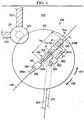
Figure 6 is a schematic end view of the drive assembly ofFigure 4 . - The following discussion is directed to various embodiments of the invention. Although one or more of these embodiments may be preferred, the embodiments disclosed should not be interpreted, or otherwise used, as limiting the scope of the disclosure, including the claims. In addition, one skilled in the art will understand that the following description has broad application, and the discussion of any embodiment is meant only to be exemplary of that embodiment, and not intended to intimate that the scope of the disclosure, including the claims, is limited to that embodiments.
- Certain terms are used throughout the following description and claims to refer to particular features or components. As one skilled in the art will appreciate, different persons may refer to the same feature or component by different names. This document does not intend to distinguish between components or features that differ in name but not function. The drawing figures are not necessarily to scale. Certain features and components herein may be shown exaggerated in scale or in somewhat schematic form and some details of conventional elements may not be shown in interest of clarity and conciseness.
- In the following discussion and in the claims, the terms "including," and "comprising" are used in an open-ended fashion, and thus should be interpreted to mean "including, but not limited to...." Also, the term "couple" or "couples" is intended to mean either an indirect or direct connection. Thus, if a first device couples to a second device, that connection may be through a direct connection, or through an indirect connection via other devices and connections. In addition, as used herein, the terms "axial" and "axially" generally mean along or parallel to a central axis (e.g., central axis of a structure), while the terms "radial" and "radially" generally mean perpendicular to the central axis. For instance, an axial distance refers to a distance measured along or parallel to the central axis, and a radial distance means a distance measured perpendicular to the central axis.
- Referring now to
Figure 2 , an embodiment of a marineseismic acquisition system 100 is schematically shown.System 100 is employed to perform marine seismic exploration operations to survey the geological formation below thesurface 110 of a body ofwater 111. In this embodiment,system 100 includes at least oneseismic survey vessel 101 that tows at least onestreamer 102 including a plurality of evenly-spaced seismic sensors or receivers 103. In this embodiment, eachstreamer 102 includes asteerable diverter 104 that controls the positioned and movement ofstreamer 102 relative tovessel 101. In particular, diverter 104positions streamer 102 at a desired offset distance fromvessel 101 and desired operating depth below thesurface 110. -
Streamers 102 may be up to several kilometers long, and are constructed in 100-150 meter sections, each section including up to thirty-five or more uniformly spaced receivers 103. In general, each receiver 103 may comprise any suitable type of marine receiver configured to pick up seismic energy signals including, without limitation, a hydrophone or a geophone. Electrical or fiber-optic cabling interconnects the plurality of receivers 103 on eachstreamer 102 and connects eachstreamer 102 tovessel 101. Seismic data acquired by receivers 103 may be digitized at or near receivers 103 and then transmitted tovessel 101 through the cabling at relatively high data transfer rates (e.g., rates in excess of 5 million bits of data per second). As shown inFigure 2 , receivers 103 are towed behindsurvey vessel 101. However, in other embodiments, the streamers (e.g., streamers 102) and the receivers (e.g., receivers 103) may be disposed along the sea floor as ocean-bottom cables. In yet other embodiments, the receivers disposed on the sea floor may be autonomous ocean-bottom nodes. Vessel-towed streamers and ocean-bottom nodes may also be used simultaneously. - Referring still to
Figure 2 ,seismic acquisition system 100 also includes a marineseismic source 200. In this embodiment,source 200 is towed behindseismic survey vessel 101. However, in other embodiments, particularly those employing a low-frequency source, the source (e.g., source 200) is preferably towed behind a different vessel than the receivers (e.g. receivers 103). Although there are many different types of marine seismic sources, in this embodiment,seismic source 200 is an oscillating piston seismic source that propagates acoustic energy signals into thewater 111 and subsurface geological formations over an extended period of time as opposed to the near instantaneous energy provided by impulsive sources.Source 200 and receivers 103 are deployed below the ocean'ssurface 110, with the optimal depth dependent on a variety of factors including, without limitation, the state of the seas (e.g., waves, currents, etc.), the towing strength of the equipment, and the desired frequency range to be produced and recorded. For a low-frequency marine seismic source producing acoustic energy in the range 2-8 Hz, for example, an optimal tow depth of the source would be approximately 60 m. - Equipment aboard
vessel 101 controls the operation ofsource 200 and receivers 103, and records the data acquired by receivers 103. The recorded data is used to produce seismic surveys that estimate the distance between thesea surface 110 and subsurface structures below thesea floor 108 such asstructure 106. To determine a distance tosubsurface structure 106,source 200 emitsseismic energy waves 107 that propagate through thewater 111 and thesea floor 108 into the subsurface geological formation. Energy waves 107 reflect off subsurface structures such asstructure 106 as "echoes" or reflected seismic energy waves 109. A portion of the reflectedseismic energy waves 109 are detected by receivers 103, converted into electrical signals, and recorded as seismic data for subsequent processing. By determining the time for theseismic waves 107 to travel fromsource 200 tosubsurface structure 106 and reflect offstructure 106 asechoes 109 to receivers 103, an estimate of the distance (both horizontally and vertically), geometry, topography, position, impendance, fluid type, and lithology of subsea geologic structures, among other parameters, can be determined. For example, certain topographical features and amplitudes of recorded seismic data are indicative of hydrocarbon reservoirs. - Referring now to
Figures 3 and4 , an embodiment of marineseismic source 200 disposed inwater 111 is shown. During use,seismic source 200 is disposed below thesurface 110 ofwater 111 as shown inFigure 2 to generate acoustic energy waves for marine seismic surveys. In this embodiment,source 200 includes anouter housing 210, apiston 220 coaxially disposed inhousing 210, and apiston drive assembly 230 disposed withinhousing 210. As will be explained in more detail below,piston drive assembly 230 reciprocatespiston 220 withinhousing 210 to generate acoustic energy waves inwater 111. Consequently, marineseismic source 200 may also be referred to as an oscillating or reciprocating piston marine seismic source. - Referring still to
Figures 3 and4 ,housing 210 has a central orlongitudinal axis 215, a first orupper end 210a, and a second orlower end 210b oppositeend 210a. In this embodiment,housing 210 includes atubular body 211 and anend cap 212 attached tobody 211.Body 211 is coaxially disposed aboutaxis 215 and has a first orupper end 211a coincident withhousing end 210a, and a second orlower end 211b coincident withhousing end 210b.Lower end 211b ofbody 211 is open towater 111, however,upper end 211a is occluded and closed byend cap 212. Accordingly,upper end 210a ofhousing 210 may also be described as a closed end, andlower end 210b ofhousing 210 may also be described as an open end.Cap 212 sealingly engagesbody 211, thereby restricting and/or preventing fluid flow into and out ofbody 211 atupper end 210a. - Together,
body 211,end cap 212, andpiston 220 define aninner chamber 213 withinhousing 210. Thus,chamber 213 extends axially betweenpiston 220 andend cap 212, and extends radially fromaxis 215 tobody 211.Inner chamber 213 is preferably filled with a gas such as air or nitrogen, and is sealed such that the ingress and egress of water intochamber 213 is restricted and/or prevented. -
Housing 210 may include one or more through ports that provide passages for electrical connections (e.g., sensor cables, electronic control wiring, etc.), power supply lines, compressed air supply lines, hydraulic fluid supply lines, and electrical connections, etc. For purposes of clarity, such ports, electrical connections, wiring, and various supply lines are not shown inFigures 3 and4 . Any ports preferably include fluid tight seals that allow the connections or lines to pass therethrough, while restricting and/or preventing the ingress or egress of water intochamber 213. - In this embodiment,
housing 210 also includes a plurality ofdrain valves 216 disposed alongbody 211.Valves 216 allow any liquid (e.g., water 111) withinchamber 213 to be drained. In addition, a plurality ofsensors 219a, b, c are coupled tohousing 210. In particular, aninternal pressure sensor 219a detects and measures the pressure withinhousing 210, anexternal pressure sensor 219b detects and measures the pressure outside of housing 210 (i.e., the pressure of water 111), and afluid level sensor 219c detects and measures the level of any liquid (e.g., water 111) that may have enteredhousing 210. - As previously describes,
piston 220 is coaxially disposed withincylinder 210. In particular,piston 220 slidingly engages the cylindrical inner surface ofbody 211 and is positioned proximally to openend 210b.Piston 220 has acentral axis 225 coaxially aligned withhousing axis 215, a first orupper end 220a, and a second orlower end 220b. - When
source 200 is disposed subsea as shown inFigure 2 ,water 111 is free to flow axially intoopen end 210b and engagepiston 220. Thus,lower end 220b faces and acts againstwater 111 withinopen end 210a ofhousing 210, whereasupper end 220a facesinner chamber 213 and acts against the gas withinchamber 213. In this embodiment, eachend 220a, b is planar. However, in other embodiments, one or both of the axial ends of the piston, (e.g., ends 220a, b of piston 220) may be non-planar. For example, the end of the piston facing the water (e.g.,lower end 220b) may comprise a cone or bullet-shaped geometry and surface as disclosed inU.S. Patent Application No. 61/7290,611 and PCT Patent Application No.PCT/US2010/62329 . - Referring still to
Figures 3 and4 , anannular seal member 221 is radially positioned betweenpiston 220 andhousing 210. In this embodiment,seal member 221 is seated in an annular recess orseal gland 222 in the radially outer surface ofpiston 220.Seal member 221 is radially compressed betweenpiston 220 andhousing 210 and sealingly engagespiston 220 andhousing 210. More specifically,seal member 221 forms an annular, radially outerdynamic seal member 221a withhousing 210 and an annular, radially innerstatic seal member 221b withpiston 220.Seals 221a, b restrict and/or prevent fluid flow betweenpiston 220 andhousing 210 aspiston 220 axially reciprocates relative tohousing 210. Accordingly,seal member 221 restricts and/or preventswater 111 external to theseismic source 200 from moving axially betweenpiston 220 andhousing 210 intoinner chamber 213, and restricts and/or prevents gas ininner chamber 213 from moving axially betweenpiston 220 andhousing 210 intowater 111 inopen end 210b. - Depending on the application and desired characteristics of the acoustic waves to be produced by source 200 (e.g., frequency range, amplitude, etc.), the maximum outer radius of
piston 220 and cylinder 210 (measured perpendicularly fromaxes 215, 225) may be varied. For most applications,piston 210 will have a maximum outer radius of the order of approximately half a meter to a few meters, depending on the desired frequency range and amplitude of acoustic radiation to be produced. - Referring now to
Figures 3-6 ,piston drive assembly 230 is disposed withininner chamber 213 and axially reciprocatespiston 220 withinhousing 210. Aspiston 220 reciprocates,lower end 220b acts against thewater 111 inopen end 210a, thereby generating acoustic energy waves that propagate downward through thewater 111. As will be explained in more detail below, the frequency and amplitude of the acoustic waves generated by reciprocatingpiston 220 may be controlled and varied bydrive assembly 230. - In this embodiment,
piston drive assembly 230 includes aflywheel 231, a drive or connectingrod 240 extending fromflywheel 231 topiston 220, a fixed or additionalmass member 250, a firstlinear actuator 251, a secondlinear actuator 252, afirst linkage 260 extending betweenfirst actuator 251 and connectingrod 240, and asecond linkage 262 extending betweensecond actuator 252 andmass member 250. As will be described in more detail below, the rotational movement offlywheel 231 drives the axial reciprocation ofpiston 220, and the frequency and amplitude of the axial oscillations ofpiston 220 are controlled byactuators linkages - Referring still to
Figures 3-6 ,flywheel 231 rotates about an axis ofrotation 235 passing through the center offlywheel 231 and oriented perpendicular toaxes flywheel 231 may rotate aboutaxis 235 in a first direction represented byarrow 237 or a second direction represented byarrow 238. In this embodiment, the density offlywheel 231 is uniform moving radially outward fromaxis 235. However, in other embodiments, the density of the flywheel (e.g., flywheel. 235) may increase moving radially outward from the rotation axis (e.g., axis 235) to enhance the rotational inertia of the flywheel having a fixed total mass. - The rotation of
flywheel 231 is powered bymotor 270. In general,motor 270 many comprise any suitable motor forrotating flywheel 231, including, Without limitation, an electric motor, a hydraulic motor, or a pneumatic motor. Further,motor 270 may drive the rotation offlywheel 231 by any suitable mechanism including, without limitation, a rotating output shaft, mating gears, direct magnetic induction of the flywheel, or combinations thereof. In this embodiment,motor 270 drives the rotation of a wheel orroller element 271 that engages the radially outer surface offlywheel 231. The rotation ofroller element 271 is transferred toflywheel 231 via frictional engagement at the contact surfaces betweenroller element 271 andflywheel 231.Motor 270 is coupled tohousing 210 such thatmotor 270 does not move translationally relative tohousing 210, although the output shaft ofmotor 270 androller element 271 are free to rotate relative tomotor 270 andhousing 210 in order to drive the rotation offlywheel 231 relative tohousing 210. In this embodiment,support members 272couple motor 270 tohousing 210 and maintain the position ofmotor 270 relative tohousing 210. - The rotational speed and direction of rotation of flywheel 231 (i.e.,
first direction 237 or second direction 238) is controlled by adjusting the output power, torque, speed, and direction of rotation ofmotor 270. Further, the rotation offlywheel 231 may be decreased and/or stopped withmotor 270 and/or a separate braking device (not shown). For example, ifmotor 270 is an electric motor, simply cutting off power to the electric motor will decrease the rotational speed of flywheel. 231 as friction between rotating components begin to convert rotational energy in the system into heat. Similarly, reconfiguring the connections tomotor 270 to convert it into a generator will act as a braking device. - As best shown in
Figure 5 , flywheel, 231 includes an elongate throughslot 232 having a central orlongitudinal axis 233, afirst end 232a atrotational axis 235 offlywheel 231, and asecond end 232bdistal axis 235 and proximal to the outer periphery offlywheel 231. In this embodiment, a projection ofaxis 233 is perpendicular to and intersectsrotational axis 235 offlywheel 231. Accordingly, in this embodiment,elongate slot 232 is radially oriented relative toaxis 235, and thus, ends 232a, b may also be referred to as radially inner and radially outer ends, respectively.Elongate slot 232 has a length L232 measured axially (relative to axis 233) betweenends 232a, b, and has a width W132 measured perpendicular toaxis 233. In this embodimentelongate slot 232 extends linearly betweenends 232a, b. However, in other embodiments, the elongate slot (e.g., slot 232) may be non-linear, but preferably has a radially inner end (e.g.,end 232a) at or near the flywheel axis (e.g., flywheel. 231) and a radially outer end (eg.,end 232b) distal the flywheel axis. - First and
second guide members slot 232 and spaced apart an axial distance D271-272 measured parallel toaxis 233. Eachguide member axis 233 that is substantially the same or slightly less than width W232 ofelongate slot 232, and thus, guidemembers axis 233 withinslot 232, but restricted from moving laterally relative to slot 232. In this embodiment, guidemembers guide member guide members same slot 232 in this embodiment, in other embodiments, the two guide members (e.g., guidemembers 271 and 272) may be positioned in different slots in the flywheel (e.g., flywheel 231). -
First guide member 271 is coupled tofirst actuator 251 viafirst linkage 260, andsecond guide member 272 is coupled tosecond actuator 252 viasecond linkage 262. As will be described in more detail below, the axial position and movement offirst guide member 271 relative toaxis 233 is controlled and adjusted byfirst actuator 251; and the axial position and movement ofsecond guide member 272 relative toaxis 233 is controlled and adjusted bysecond actuator 252. In this embodiment,first actuator 251 andsecond actuator 252 may be operated independently of each other such that the axial positions and movement ofguide members axis 233 may be varied relative to each other. For example, axial distance D271-272 betweenmembers source 200. In other embodiments, the operation of the actuators (e.g.,actuators 251, 252) may be linked to each other such that the axial distance between the guide members (e.g., axial distance D27-272 betweenmembers 271, 272) is fixed, or varied pursuant to a predetermined algorithm. - Referring again to
Figures 3-5 , elongate connectingrod 240 has a central orlongitudinal axis 245, a first orpiston end 240a coupled topiston 220, and a second orflywheel end 240b coupled to guidemember 271.First end 240a is pivotally coupled topiston 220 such that connectingrod 240 is free to pivot or rotate aboutfirst end 240a relative topiston 220, andsecond end 240b is pivotally coupled to guidemember 271 such that connectingrod 240 is free to pivot or rotate aboutsecond end 240b relative to guidemember 271,elongate slot 232, andflywheel 231. - Referring specifically to
Figure 5 ,first actuator 251 is secured toflywheel 231 and is coupled tofirst linkage 260,first guide member 271, and end 240b of connectingrod 240; andsecond actuators 252 is secured toflywheel 231 and is coupled tosecond linkage 262,second guide member 272, andmass member 250. In this embodiment, eachlinkage actuator member axis 233 passes throughend 240b and the center ofmass member 250. -
First actuator 251 controls the axial position and movement offirst linkage 260,first guide member 271, and end 240b alongslot 232 andaxis 233, and hence, also controls the radial position and movement offirst linkage 260,first guide member 271, and end 240b relative to flywheel.axis 235. Further,second actuator 252 controls the axial position and movement ofsecond linkage 262,second guide member 272, andmass member 250 alongslot 232 andaxis 233, and hence, also controls the radial position and movement ofsecond linkage 262,second guide member 272, andmass member 250 relative toaxis 235. Sinceactuators move linkages axis 233, it may also be referred to as a "linear actuator." Although two actuators (e.g.,actuators 251, 252) are included in this embodiment to control the position and movement of the end of the connecting rod (e.g.,end 240b) and the mass member (e.g., mass member 250) relative to the flywheel axis, in other embodiments, the position and movement of the end of the connecting rod and the mass member relative to the flywheel axis may be controlled by a single actuator. Further, although there is asingle mass member 250 in this embodiment, in other embodiments there may be two or more mass members, each with their own actuator to position them, for example disposed and controlled so as to maintain the center of mass of the flywheel system at theaxis 235 throughout the operation of the source. - The amplitude of oscillations of
piston 220 depend on the radial position ofsecond end 240b relative toflywheel axis 235. More specifically, the greater the radial distance measured fromaxis 235 tosecond end 240b (along slot 232), the greater the amplitude of oscillations ofpiston 220. Conversely, the smaller the radial distance measured fromaxis 235 tosecond end 240b (along slot 232), the smaller the amplitude of oscillations ofpiston 220. - The frequency of oscillations of
piston 220 depend on the rotational speed offlywheel 231. More specifically, the greater the rotational speed offlywheel 231, the greater the frequency of oscillations ofpiston 220, and the lower the rotational speed offlywheel 231, the lower the frequency of oscillations ofpiston 220. The rotational speed offlywheel 231 depends on a variety of factors including, without limitation, the rotational energy input intoflywheel 231, decreases in the rotational energy offlywheel 231 due to friction and acoustic radiation losses, and the moment of inertia offlywheel 231. In general, the greater the rotational energy input intoflywheel 231, the greater the rotational speed offlywheel 231. For a given rotational energy input intoflywheel 231, an increase in the moment of inertia offlywheel 231 will decrease the rotational speed offlywheel 231, and a decrease in the moment of inertia offlywheel 231 will increase the rotational speed offlywheel 231. The moment of inertia offlywheel 231 may be increased by movingmass 250 radially outward relative toaxis 235, and deceased by movingmass 250 radially inward relative toaxis 235. - Without being limited by this or any particular theory, the amplitude of oscillations of
piston 220 and the frequency of oscillations ofpiston 220 determine the amplitude and frequency of the acoustic energy waves output byseismic source 200. More specifically, the amplitude and frequency of the acoustic waves generated bysource 200 are proportional to the amplitude of the oscillations ofpiston 220 times the square of the frequency of the oscillations ofpiston 220. Thus, by varying the radial position ofsecond end 240b relative toflywheel axis 235, the amplitude of oscillations ofpiston 220 and associated acoustic energy waves may be controlled; and by varying the rotational speed of flywheel 231 (e.g., by varying the rotational energy input intoflywheel 231 and by varying the moment of inertia offlywheel 231 with mass 250), the frequency of oscillations ofpiston 220 and associated acoustic energy waves may be controlled. - In general,
actuators second end 240b andmass member 250, respectively, relative toaxis 235 including, without limitation, a pneumatic actuator, a hydraulic actuator, an electric actuator, a motor, etc. In this embodiment, eachactuator actuators second end 240b) and the added mass member (e.g., mass member 250) may be operated by means other than simply moving the linkage (e.g.,linkage 260, 262) linearly. For example, in other embodiments, the actuator(s) may rotate a threaded shaft that threadingly engages the guide members (e.g., guidemembers 271, 272), which are restricted from rotating with the threaded shaft. As a result, the rotation of the threaded shaft controls the radial position and movement of the guide member(s) relative to the rotation axis (e.g., rotation axis 235) - the direction of rotation controls whether the guide members move radially inward or outward, and the speed of the rotation controls the speed at which the guide members move radially.Actuators actuators flywheel 231 without interference (e.g., by electric brushes that conduct current between stationary wires androtating actuators 251, 252). - Referring now to
Figures 4 and5 , in this embodiment, eachactuator sensor 280 that detects and measures the radial position ofsecond end 240b andmass member 250, respectively, relative torotation axis 235.Sensors 280 transmit the position data to acontrol system 281 coupled tohousing 210 within chamber 213 (Figures 3 and4 ).Control system 281 monitors the radial positions ofsecond end 240b andmass member 250 relative toaxis 235, and adjusts the radial positions ofsecond end 240b andmass member 250 relative toaxis 235 by controllingactuators source 200. By monitoring and controlling the radial positions ofsecond end 240b,control system 281 controls the frequency and amplitude of the acoustic energy waves produced bysource 200. In addition,control system 281 controls the output power, torque, rotational speed, and rotational direction of the motor that drives the rotation offlywheel 231. In this embodiment,control system 281 communicates wirelessly withsensors 280 andactuators motor 270 by wire. However, in general, the control system (e.g., control system 281) may communicates with the sensors (e.g., sensors 280), the actuators (e.g.,actuators 251, 252) and the motor (e.g., motor 270) by any suitable means, provided any wiring is configured to allow rotation of the flywheel (e.g., Flywheel 231) and the sensors (e.g., sensors 280) coupled thereto Without interference.Sensors 219a, b, c may also communicate measured pressure and fluid level data to controlsystem 281. The data acquired bydontrol system 281 is communicated to surfacevessel 101 for monitoring and analysis, and control signals for the operation ofdrive assembly 230 are communicated fromsurface vessel 101 to controlsystem 281. - Referring again to
Figures 3-5 ,seismic source 200 is preferably operated in a cyclical fashion. Each cycle includes three phases - (a) an acceleration phase; (b) a sweep phase; and (c) a reset phase. In the acceleration phase,second end 240b of connectingrod 240 is positioned at center of flywheel 231 (i.e.; at rotation axis 235) or just off-center, and a rotational torque is applied to flywheel 231 (e.g., with roller element 271) to increase the rotational speed offlywheel 231 until a predetermined and desirable rotational speed offlywheel 231 is achieved. It should be appreciated that whensecond end 240b and guidemember 271 are disposed at rotation axis 235 (i.e.,second end 240b and guidemember 271 are disposed at the center of flywheel. 231),piston 220 does not oscillate at all. - In the sweep phase, the rotational torque applied to
flywheel 231 may be removes, and the radial distance measured fromaxis 235 tosecond end 240b is varied, causing the amplitude of the oscillations ofpiston 220 and associated acoustic radiation to vary. For example, during a sweep, the radial distance measured fromaxis 235 tosecond end 240b may be increased, causing the amplitude of the oscillations ofpiston 220 and associated acoustic radiation to increase. Alternatively, during a sweep, the radial distance measured fromaxis 235 tosecond end 240b may be decreased, causing the amplitude of oscillations ofpiston 220 and associated acoustic radiation to decrease. Still further, the radial distance measured fromaxis 235 tosecond end 240b may increased and then decreased during a single sweep to increase and then decrease the amplitude ofpiston 220 and associated acoustic radiation, or decreased and then increased during a sweep to decrease and then increase the amplitude ofpiston 200 and associated acoustic radiation. In this manner, the amplitude of oscillations ofpiston 220 and associated acoustic radiation can be varied and controlled during the sweep phase. - In the sweep phase, the rotational speed of
flywheel 231 is varied, causing the frequency of oscillation ofpiston 220 to vary. In particular, during a sweep, the rotational energy impacted toflywheel 231 in the acceleration phase is lost to friction and the output acoustic radiation. These energy losses tend to decrease the rotational speed of flywheel. 231, which would also decrease the frequency of oscillations ofpiston 220. By movingmass 250 radially outward fromaxis 235 alongslot 232 during a sweep, thereby effectively increasing the moment of inertia of flywheel, 231, the rotational speed offlywheel 231 may be further decreased. Thus, by maintaining or increasing the radial distance fromaxis 235 tomass 250 during a sweep, the rotational speed offlywheel 231 is decreased, and the frequency of oscillations ofpiston 220 and associated acoustic radiation is decreased. However, by movingmass 250 radially inward fromaxis 235 alongslot 232 during a sweep, thereby effectively decreasing the moment of inertia offlywheel 231, the rotational speed offlywheel 231 may be increased, and the frequency of oscillations ofpiston 220 and associated acoustic radiation may be increased. In some cases, the radial distance fromaxis 235 tomass 250 may be increased and then decreased to increase the moment of inertia offlywheel 231 and then decrease the moment of inertia offlywheel 231, or the radial distance fromaxis 235 tomass 250 may be decreased and then increased to decrease the moment of inertia of flywheel. 231 and then increase the moment of inertia offlywheel 231. In this manner, the frequency of oscillations ofpiston 220 and associated acoustic radiation can be varied and controlled during the sweep phase. - In a preferred embodiment, during the sweep phase,
end 240b of connectingrod 240 is moved radially outward relative toflywheel axis 235 withactuator 251 andlinkage 260, and additionalmass member 250 is moved radially outward relative torotation axis 235 withactuator 252 andlinkage 262. As a result, the amplitude of oscillations ofpiston 220 increase and the frequency of oscillations ofpiston 220 decreased, and thus, the amplitude of the acoustic waves generated bysource 200 increase and the frequency of the acoustic waves generated bysource 200 decrease. The radial distance betweenend 240b androtation axis 235 is increased untilend 240b is positioned atend 232b ofslot 232 and the minimum operating frequency and maximum operating amplitude ofpiston 220 andsource 200 are achieved. In this embodiment,sources 200 offers the potential to generate acoustic energy waves with frequencies as low as 0.5 Hz. - During the sweep phase, as
piston 220 begins to move translationally relative toflywheel axis 235, some of the kinetic energy inflywheel 231 is transferred topiston 220 and its associated mass (i.e., the mass of the entrainedwater 111 inend 210b that moves with piston 220), and to additionalmass member 250. In other words, at least a portion of the rotational kinetic energy imparted toflywheel 231 during the acceleration period is transferred topiston 220 andmass member 250. Thus, during the sweep period, the initial rotational kinetic energy offlywheel 231 is shared amongflywheel 231, piston 220 (and its associated mass), and additionalmass member 250. Energy that is transferred to additionalmass member 250 helps to smooth the axial motion ofpiston 220. More specifically, additionalmass member 250 allows for relatively fine control of the proportion of energy that is transferred from flywheel. 231 topiston 220 during the sweep phase. In particular, control of the radial motion and position of additionalmass member 250 relative toaxis 235 allows the amplitude and frequency of the motion ofpiston 220 during the sweep to be independently controlled to achieve a desired amplitude and/or frequency (or desired amplitude and/or frequency range). Without being limited by this or any particular theory, this helps to produce a smoother, more nearly sinusoidal motion ofpiston 220, and hence, a purer acoustic output spectrum with fewer undesired harmonics. Without the additional degree of freedom of control allowed by additionalmass member 250,piston 220 would move in a less controlled manner, producing undesirable harmonics in the acoustic output spectrum. - In the reset phase,
motor 270 and/or separate brake are employed to decrease and/or stop the rotational speed offlywheel 231. In addition,flywheel end 240b of connectingrod 240 is moved radially inward toflywheel axis 235 withactuator 251 andlinkage 260, andmass member 250 is moved radially inward towardflywheel axis 235 withactuator 252 andlinkage 262, thereby resettingsource 200 and preparingsource 200 for the next cycle. Oncesource 200 is reset, the cycle may be repeated starting with the acceleration phase. - Embodiments described herein (e.g., source 200) coffer the advantages of a conventional resonant system - once the system has been fully excited, further input power is only required to overcome damping losses and energy lost to acoustic radiation. However, unlike a conventional resonant system, the mechanical device herein described lessens the required peak input power even further by spreading its input over the entire quiet non-sweep phase (or optionally, even allowing power to be input continuously). More specifically, during the operation of most conventional oscillating piston seismic source, the actuation energy that drives the oscillation of the piston is input during the sweep phase. Typically, the duration of a sweep is relatively small compared to the total time between sweeps. Since the actuation energy must be input within a relatively small time window, the associated power requirements are relatively large. To the contrary, in embodiments described herein (e.g., source 200), the actuation energy that is eventually used to drive the oscillation of
piston 220 is input prior to the sweep phase, thereby allowing the actuation energy to be input over a relatively long period of time (as compared to the duration of the sweep phase). Thus,flywheel 231 can be brought up to speed during the acceleration period using moderate power, rather than requiring high power for the relatively short duration of the sweep. - In general, the components of reciprocating piston
seismic source 200 described herein (e.g.,piston 220,housing 210,flywheel 231,mass 250, etc.) may be made from any suitable material(s) including, without limitation, metals and metal alloys (e.g., aluminum, stainless steel, etc.), non-metals (e.g., ceramics, polymers, etc.), composites (e.g., carbon fiber and epoxy composite, etc.), or combinations thereof Since the piston (e.g., piston 220) and cylinder (e.g., housing 210) are exposed to subsea conditions, each preferably comprises a rigid, durable material capable of withstanding corrosion such as stainless steel. - While preferred embodiments have been shown and described, modifications thereof can be made by one skilled in the art without departing from the scope or teachings herein. The embodiments described herein are exemplary only and are not limiting. Many variations and modifications of the systems, apparatus, and processes described herein are possible and are within the scope of the invention. For example, the relative dimensions of various parts, the materials from which the various parts are made, and other parameters can be varied. Accordingly, the scope of protection is not limited to the embodiments described herein, but is only limited by the claims that follow, the scope of which shall include all equivalents of the subject matter of the claims.
Claims (23)
- A marine seismic source, (200) comprising:a housing (210) having a central axis, (215) an open end, (210b) and a closed end (210a) opposite the open end;a. piston (220) coaxially disposed within the housing;a flywheel (231) disposed within the housing and axially positioned between the closed end and the piston, wherein the flywheel is configured to rotate about a rotational axis;a connecting rod (340) moveably coupling the piston to the flywheel;wherein the connecting rod has a first end (240a) pivotally coupled to the piston and a second (240b) end pivotally coupled to the flywheel;characterized in that the second end of the connecting rod has a first position at a first distance measured radially from the rotational axis, and a second position at a second distance measured radially from the rotational axis, wherein the first distance is less than the second distance.
- The marine seismic source of claim 1, further comprising an added mass member moveably coupled to the flywheel, wherein the added mass member is configured to move radially relative to the rotational axis.
- The marine seismic source of claim 1, further comprising an added mass member moveably coupled to the flywheel, wherein the added mass member has a first position at a third distance measured radially from the rotational axis and a second position at a fourth distance measured radially from the rotational axis, wherein the third radial distance is less than the fourth radial distance, and wherein the third radial distance is greater than the first radial distance and the fourth radial distance is greater than the second radial distance.
- The marine seismic source of claim 2, further comprising a first actuator configured to move the second end of the connecting rod radially relative to the rotational axis.
- The marine seismic source of claim 4, further comprising a second actuator configured to move the added mass member radially relative to the rotational axis.
- The marine seismic source of claim 5, wherein the first actuator and the second actuator are attached to the flywheel.
- The marine seismic source of claim 2, further comprising a motor disposed within the housing and axially positioned between the piston and the closed end, wherein the motor is coupled to the housing and configured to rotate the flywheel.
- The marine seismic source of claim 5, wherein the flywheel includes an elongate through slot having a radially inner end at or proximal the rotation axis and a radially outer end distal the rotation axis;
wherein the second end of the connecting rod is pivotally coupled to a first guide member that is slidingly disposed in the slot; and
wherein the added mass member is coupled to a second guide member that is slidingly disposed in the slot. - The marine seismic source of claim 8, further comprising a first linkage extending from the first actuator to the first guide member and a second linkage extending from the second actuator to the second guide member.
- The marine seismic source of claim 5, wherein the first actuator and the second actuator are linear actuators.
- A method for generating a marine seismic energy wave in a body of water, comprising:(a) providing a seismic source, (200) wherein the seismic source includes:a housing (210) having a closed end and an open end;a piston (220) slidingly disposed within the housing;a flywheel (231) disposed in the housing between the closed end and the piston, wherein the flywheel is configured to rotate about a rotational axis;a connecting rod (240) having a first end pivotally coupled to the piston and a second end pivotally coupled to the flywheel;(b) positioning the seismic source in the water;(c) rotating the flywheel about the rotational axis;(d) changing a first distance measured radially from the rotational axis to the second end of the connecting rod during (c).
- The method of claim 11, further comprising:(e) changing a second distance measured radially from the rotational axis to an added mass member moveably coupled to the flywheel during (c).
- The method of claim 12, wherein (d) comprises increasing or decreasing the first distance during (c).
- The method of claim 13, further comprising decreasing or increasing the first distance after (d).
- The method of claim 12, further comprising:(f) generating acoustic energy waves with the seismic source during (d), wherein the acoustic energy waves have a frequency and an amplitude, wherein the frequency or amplitude of the acoustic energy waves change during (d); and(g) transmitting the acoustic energy wave through the water.
- The method of claim 15, wherein (d) further comprises increasing the first distance during (c);
wherein (e) further comprises increasing the second distance during (c);
wherein (f) further comprises decreasing the frequency of the acoustic energy waves during (d) and increasing the amplitude of the acoustic energy waves during (d). - The method of claim 12, further comprising:increasing a rotational speed of the flywheel before (d);decreasing the rotational speed of the flywheel after (d);decreasing the first distance after (e); anddecreasing the second distance after (e).
- The method of claim 11, wherein the flywheel of the seismic source includes an elongate through slot extending radially outward from the rotational axis;
wherein the second end of the connecting rod is coupled to a first guide member slidingly disposed in the through slot;
wherein the added mass member is coupled to a second guide member slidingly disposed in the through slot;
wherein (d) comprises moving the first guide member along the through slot; and
wherein (e) comprises moving the second guide member along the through slot. - A method for generating a marine seismic energy wave in a body of water, comprising:(a) positioning a marine seismic source (200) in the water, wherein the seismic source includes:a housing (210) having a closed end and an open end;a piston (220) slidingly disposed within the housing;a flywheel (231) disposed in the housing between the closed end and the piston, wherein the flywheel is configured to rotate about a rotational axis;a connecting rod (240) having a first end pivotally coupled to the piston and a second end pivotally coupled to the flywheel;(b) positioning the second end of the connecting rod at or proximal the rotational axis of the flywheel;(c) applying rotational torque to the flywheel after (b);(d) increasing the rotational speed of the flywheel during (c);(e) radially moving the second end of the connecting rod relative to the rotational axis.
- The method of claim 19, wherein (e) occurs after (c).
- The method of claim 20, wherein (e) comprises moving the second end of the connecting rod radially outward relative to the rotational axis.
- The method of claim 21, further comprising:(t) decreasing the rotational speed of the flywheel; and(g) moving the second end of the connecting rod radially inward relative to the rotational axis.
- The method of claim 22, repeating (c), (d), and (e) after (f) and (g).
Applications Claiming Priority (2)
| Application Number | Priority Date | Filing Date | Title |
|---|---|---|---|
| US35259910P | 2010-06-08 | 2010-06-08 | |
| PCT/US2011/039619 WO2011156482A2 (en) | 2010-06-08 | 2011-06-08 | Marine mechanical seismic source |
Publications (2)
| Publication Number | Publication Date |
|---|---|
| EP2580609A2 EP2580609A2 (en) | 2013-04-17 |
| EP2580609B1 true EP2580609B1 (en) | 2016-08-10 |
Family
ID=44627391
Family Applications (1)
| Application Number | Title | Priority Date | Filing Date |
|---|---|---|---|
| EP11727075.1A Active EP2580609B1 (en) | 2010-06-08 | 2011-06-08 | Marine mechanical seismic source |
Country Status (10)
| Country | Link |
|---|---|
| US (1) | US8794372B2 (en) |
| EP (1) | EP2580609B1 (en) |
| AU (1) | AU2011264920B2 (en) |
| BR (1) | BR112012030153B1 (en) |
| CA (1) | CA2799221C (en) |
| DK (1) | DK2580609T3 (en) |
| EA (1) | EA022286B1 (en) |
| EG (1) | EG26978A (en) |
| MX (1) | MX2012013519A (en) |
| WO (1) | WO2011156482A2 (en) |
Families Citing this family (22)
| Publication number | Priority date | Publication date | Assignee | Title |
|---|---|---|---|---|
| US9507039B2 (en) * | 2010-12-13 | 2016-11-29 | Schlumberger Technology Corporation | Seismic source, system, and method |
| CN103015552B (en) * | 2011-09-22 | 2014-11-05 | 同济大学 | Shock and breakage preventive deformation recording type buckling restrained brace and manufacturing method thereof |
| US10473803B2 (en) | 2013-02-08 | 2019-11-12 | Pgs Geophysical As | Marine seismic vibrators and methods of use |
| US20140238771A1 (en) * | 2013-02-22 | 2014-08-28 | Cgg Services Sa | Marine acoustic projector piston for vibrator source element and method |
| US9322945B2 (en) | 2013-03-06 | 2016-04-26 | Pgs Geophysical As | System and method for seismic surveying using distributed sources |
| US9594173B2 (en) | 2013-03-08 | 2017-03-14 | Cgg Services Sas | Method and system for augmenting frequency range of conventional marine seismic source with low-frequency |
| US9645264B2 (en) | 2013-05-07 | 2017-05-09 | Pgs Geophysical As | Pressure-compensated sources |
| US9995834B2 (en) | 2013-05-07 | 2018-06-12 | Pgs Geophysical As | Variable mass load marine vibrator |
| US20140340511A1 (en) * | 2013-05-14 | 2014-11-20 | Android Industries Llc | Uniformity Testing System and Methodology for Utilizing the Same |
| US9864080B2 (en) | 2013-05-15 | 2018-01-09 | Pgs Geophysical As | Gas spring compensation marine acoustic vibrator |
| US9618637B2 (en) | 2013-09-20 | 2017-04-11 | Pgs Geophysical As | Low frequency marine acoustic vibrator |
| US9341725B2 (en) | 2013-09-20 | 2016-05-17 | Pgs Geophysical As | Piston integrated variable mass load |
| US9360574B2 (en) | 2013-09-20 | 2016-06-07 | Pgs Geophysical As | Piston-type marine vibrators comprising a compliance chamber |
| US9507037B2 (en) | 2013-09-20 | 2016-11-29 | Pgs Geophysical As | Air-spring compensation in a piston-type marine vibrator |
| EA032502B1 (en) * | 2013-10-23 | 2019-06-28 | Бипи Корпорейшн Норд Америка Инк. | System and method for resonator frequency control by active feedback |
| US9612347B2 (en) | 2014-08-14 | 2017-04-04 | Pgs Geophysical As | Compliance chambers for marine vibrators |
| US9389327B2 (en) | 2014-10-15 | 2016-07-12 | Pgs Geophysical As | Compliance chambers for marine vibrators |
| US10488542B2 (en) | 2014-12-02 | 2019-11-26 | Pgs Geophysical As | Use of external driver to energize a seismic source |
| WO2016094618A1 (en) * | 2014-12-12 | 2016-06-16 | Conocophillips Company | Segmented base plate seismic sweeps |
| CN106199688B (en) * | 2016-06-29 | 2018-02-23 | 成都理工大学 | It is integrated with the high-precision three-component microseism wave detector and implementation method of active focus |
| CN111323822B (en) * | 2020-05-06 | 2020-10-16 | 三门梅格测量仪器有限公司 | A marine seismic detector that can be automatically and stably installed |
| IT202200021414A1 (en) * | 2022-10-18 | 2024-04-18 | Advanced Scient Sensors And Systems S R L | Directional sensor for measuring infrasound, and related infrasound emitter |
Family Cites Families (15)
| Publication number | Priority date | Publication date | Assignee | Title |
|---|---|---|---|---|
| FR715055A (en) * | 1931-04-10 | 1931-11-25 | Mechanical vibrator | |
| US2062329A (en) | 1932-04-21 | 1936-12-01 | Aluminum Co Of America | Thermal treatment of aluminum alloys containing copper |
| US2675086A (en) * | 1948-05-03 | 1954-04-13 | Socony Vacuum Oil Co Inc | Method and apparatus for seismic prospecting |
| US4207154A (en) * | 1957-06-27 | 1980-06-10 | Lemelson Jerome H | Wave generating apparatus and method |
| USRE26748E (en) * | 1968-10-22 | 1969-12-30 | Mechanical imploder and method for generating under water seismic signals | |
| US4061443A (en) * | 1976-12-02 | 1977-12-06 | General Motors Corporation | Variable stroke compressor |
| GB2307743B (en) * | 1995-12-02 | 1999-07-14 | Nigel Allister Anstey | Swinging-weight vibrator for seismic exploration |
| SE9700896L (en) * | 1997-03-13 | 1998-02-09 | Kockum Sonics Ab | sound Generator |
| US6230840B1 (en) * | 1998-10-16 | 2001-05-15 | Western Atlas International, Inc. | Marine vibrator |
| US7216738B2 (en) * | 2005-02-16 | 2007-05-15 | Halliburton Energy Services, Inc. | Acoustic stimulation method with axial driver actuating moment arms on tines |
| US20080232636A1 (en) * | 2007-03-23 | 2008-09-25 | Sonic Dynamics, Llc | Sonic piston |
| WO2009012424A2 (en) * | 2007-07-19 | 2009-01-22 | Terralliance Technologies, Inc. | Seismic wave generating apparatus and method |
| US20090320640A1 (en) * | 2008-06-30 | 2009-12-31 | Christopher Mark Elliott | Variable inertia flywheel |
| BR112012016276B1 (en) * | 2009-12-29 | 2020-03-03 | Bp Exploration Operating Company Limited | MARINE SEISMIC SOURCE |
| US8746188B2 (en) * | 2010-03-17 | 2014-06-10 | Larry C. Wilkins | Internal combustion engine with hydraulically-affected stroke |
-
2011
- 2011-06-08 DK DK11727075.1T patent/DK2580609T3/en active
- 2011-06-08 EP EP11727075.1A patent/EP2580609B1/en active Active
- 2011-06-08 WO PCT/US2011/039619 patent/WO2011156482A2/en not_active Ceased
- 2011-06-08 AU AU2011264920A patent/AU2011264920B2/en not_active Ceased
- 2011-06-08 MX MX2012013519A patent/MX2012013519A/en active IP Right Grant
- 2011-06-08 CA CA2799221A patent/CA2799221C/en active Active
- 2011-06-08 BR BR112012030153-5A patent/BR112012030153B1/en active IP Right Grant
- 2011-06-08 EA EA201201574A patent/EA022286B1/en not_active IP Right Cessation
- 2011-06-08 US US13/156,191 patent/US8794372B2/en active Active
-
2012
- 2012-12-05 EG EG2012122017A patent/EG26978A/en active
Also Published As
| Publication number | Publication date |
|---|---|
| EA201201574A1 (en) | 2013-05-30 |
| US20110297476A1 (en) | 2011-12-08 |
| AU2011264920B2 (en) | 2014-02-27 |
| BR112012030153A2 (en) | 2017-06-27 |
| BR112012030153B1 (en) | 2020-10-13 |
| EP2580609A2 (en) | 2013-04-17 |
| MX2012013519A (en) | 2013-01-24 |
| CA2799221C (en) | 2018-06-05 |
| EA022286B1 (en) | 2015-12-30 |
| US8794372B2 (en) | 2014-08-05 |
| EG26978A (en) | 2015-03-01 |
| WO2011156482A3 (en) | 2012-05-10 |
| CA2799221A1 (en) | 2011-12-15 |
| DK2580609T3 (en) | 2016-09-19 |
| WO2011156482A2 (en) | 2011-12-15 |
Similar Documents
| Publication | Publication Date | Title |
|---|---|---|
| CA2799221C (en) | Marine mechanical seismic source | |
| AU2011264920A1 (en) | Marine mechanical seismic source | |
| AU2010343107B2 (en) | Marine seismic source | |
| US8446798B2 (en) | Marine acoustic vibrator having enhanced low-frequency amplitude | |
| US9864080B2 (en) | Gas spring compensation marine acoustic vibrator | |
| EP2981849A1 (en) | A magneto-hydrodynamic seismic source and a method of marine seismic surveying | |
| MX2014001575A (en) | Marine seismic vibrators and methods of use. | |
| WO1998041885A1 (en) | Underground acoustic wave transmitter, receiver, transmitting/receiving method, and underground exploration using this | |
| US5080189A (en) | Electro-hydraulic dipole vibrator | |
| US10481286B2 (en) | Marine seismic vibrator for low frequency and methods of use | |
| EP3232231B1 (en) | Control system for a marine vibrator | |
| US20170168174A1 (en) | Method and system for generating low-frequency seismic signals with a flow-modulated source | |
| US20180003834A1 (en) | Pressure compensation for a marine vibrator | |
| US20140177386A1 (en) | Volumetric and non-volumetric sources-based seismic survey and method | |
| AU2013202743B1 (en) | A Seismic Energy Source and a Method of Marine Seismic Surveying |
Legal Events
| Date | Code | Title | Description |
|---|---|---|---|
| PUAI | Public reference made under article 153(3) epc to a published international application that has entered the european phase |
Free format text: ORIGINAL CODE: 0009012 |
|
| 17P | Request for examination filed |
Effective date: 20130104 |
|
| AK | Designated contracting states |
Kind code of ref document: A2 Designated state(s): AL AT BE BG CH CY CZ DE DK EE ES FI FR GB GR HR HU IE IS IT LI LT LU LV MC MK MT NL NO PL PT RO RS SE SI SK SM TR |
|
| RIN1 | Information on inventor provided before grant (corrected) |
Inventor name: MOORE, STUART Inventor name: THOMPSON, MARTIN Inventor name: HARPER, MARK |
|
| DAX | Request for extension of the european patent (deleted) | ||
| GRAP | Despatch of communication of intention to grant a patent |
Free format text: ORIGINAL CODE: EPIDOSNIGR1 |
|
| INTG | Intention to grant announced |
Effective date: 20150929 |
|
| RIN1 | Information on inventor provided before grant (corrected) |
Inventor name: MOORE, STUART Inventor name: HARPER, MARK Inventor name: THOMPSON, MARTIN |
|
| INTG | Intention to grant announced |
Effective date: 20160302 |
|
| GRAS | Grant fee paid |
Free format text: ORIGINAL CODE: EPIDOSNIGR3 |
|
| GRAA | (expected) grant |
Free format text: ORIGINAL CODE: 0009210 |
|
| AK | Designated contracting states |
Kind code of ref document: B1 Designated state(s): AL AT BE BG CH CY CZ DE DK EE ES FI FR GB GR HR HU IE IS IT LI LT LU LV MC MK MT NL NO PL PT RO RS SE SI SK SM TR |
|
| REG | Reference to a national code |
Ref country code: GB Ref legal event code: FG4D |
|
| REG | Reference to a national code |
Ref country code: CH Ref legal event code: EP Ref country code: AT Ref legal event code: REF Ref document number: 819556 Country of ref document: AT Kind code of ref document: T Effective date: 20160815 |
|
| REG | Reference to a national code |
Ref country code: IE Ref legal event code: FG4D |
|
| REG | Reference to a national code |
Ref country code: DK Ref legal event code: T3 Effective date: 20160915 |
|
| REG | Reference to a national code |
Ref country code: DE Ref legal event code: R096 Ref document number: 602011029016 Country of ref document: DE |
|
| REG | Reference to a national code |
Ref country code: NL Ref legal event code: FP |
|
| REG | Reference to a national code |
Ref country code: NO Ref legal event code: T2 Effective date: 20160810 |
|
| REG | Reference to a national code |
Ref country code: LT Ref legal event code: MG4D |
|
| REG | Reference to a national code |
Ref country code: AT Ref legal event code: MK05 Ref document number: 819556 Country of ref document: AT Kind code of ref document: T Effective date: 20160810 |
|
| PG25 | Lapsed in a contracting state [announced via postgrant information from national office to epo] |
Ref country code: FI Free format text: LAPSE BECAUSE OF FAILURE TO SUBMIT A TRANSLATION OF THE DESCRIPTION OR TO PAY THE FEE WITHIN THE PRESCRIBED TIME-LIMIT Effective date: 20160810 Ref country code: IS Free format text: LAPSE BECAUSE OF FAILURE TO SUBMIT A TRANSLATION OF THE DESCRIPTION OR TO PAY THE FEE WITHIN THE PRESCRIBED TIME-LIMIT Effective date: 20161210 Ref country code: HR Free format text: LAPSE BECAUSE OF FAILURE TO SUBMIT A TRANSLATION OF THE DESCRIPTION OR TO PAY THE FEE WITHIN THE PRESCRIBED TIME-LIMIT Effective date: 20160810 Ref country code: RS Free format text: LAPSE BECAUSE OF FAILURE TO SUBMIT A TRANSLATION OF THE DESCRIPTION OR TO PAY THE FEE WITHIN THE PRESCRIBED TIME-LIMIT Effective date: 20160810 Ref country code: LT Free format text: LAPSE BECAUSE OF FAILURE TO SUBMIT A TRANSLATION OF THE DESCRIPTION OR TO PAY THE FEE WITHIN THE PRESCRIBED TIME-LIMIT Effective date: 20160810 Ref country code: IT Free format text: LAPSE BECAUSE OF FAILURE TO SUBMIT A TRANSLATION OF THE DESCRIPTION OR TO PAY THE FEE WITHIN THE PRESCRIBED TIME-LIMIT Effective date: 20160810 |
|
| PG25 | Lapsed in a contracting state [announced via postgrant information from national office to epo] |
Ref country code: LV Free format text: LAPSE BECAUSE OF FAILURE TO SUBMIT A TRANSLATION OF THE DESCRIPTION OR TO PAY THE FEE WITHIN THE PRESCRIBED TIME-LIMIT Effective date: 20160810 Ref country code: GR Free format text: LAPSE BECAUSE OF FAILURE TO SUBMIT A TRANSLATION OF THE DESCRIPTION OR TO PAY THE FEE WITHIN THE PRESCRIBED TIME-LIMIT Effective date: 20161111 Ref country code: PT Free format text: LAPSE BECAUSE OF FAILURE TO SUBMIT A TRANSLATION OF THE DESCRIPTION OR TO PAY THE FEE WITHIN THE PRESCRIBED TIME-LIMIT Effective date: 20161212 Ref country code: SE Free format text: LAPSE BECAUSE OF FAILURE TO SUBMIT A TRANSLATION OF THE DESCRIPTION OR TO PAY THE FEE WITHIN THE PRESCRIBED TIME-LIMIT Effective date: 20160810 Ref country code: PL Free format text: LAPSE BECAUSE OF FAILURE TO SUBMIT A TRANSLATION OF THE DESCRIPTION OR TO PAY THE FEE WITHIN THE PRESCRIBED TIME-LIMIT Effective date: 20160810 Ref country code: ES Free format text: LAPSE BECAUSE OF FAILURE TO SUBMIT A TRANSLATION OF THE DESCRIPTION OR TO PAY THE FEE WITHIN THE PRESCRIBED TIME-LIMIT Effective date: 20160810 Ref country code: AT Free format text: LAPSE BECAUSE OF FAILURE TO SUBMIT A TRANSLATION OF THE DESCRIPTION OR TO PAY THE FEE WITHIN THE PRESCRIBED TIME-LIMIT Effective date: 20160810 |
|
| PG25 | Lapsed in a contracting state [announced via postgrant information from national office to epo] |
Ref country code: RO Free format text: LAPSE BECAUSE OF FAILURE TO SUBMIT A TRANSLATION OF THE DESCRIPTION OR TO PAY THE FEE WITHIN THE PRESCRIBED TIME-LIMIT Effective date: 20160810 Ref country code: EE Free format text: LAPSE BECAUSE OF FAILURE TO SUBMIT A TRANSLATION OF THE DESCRIPTION OR TO PAY THE FEE WITHIN THE PRESCRIBED TIME-LIMIT Effective date: 20160810 |
|
| REG | Reference to a national code |
Ref country code: DE Ref legal event code: R097 Ref document number: 602011029016 Country of ref document: DE |
|
| PG25 | Lapsed in a contracting state [announced via postgrant information from national office to epo] |
Ref country code: BE Free format text: LAPSE BECAUSE OF FAILURE TO SUBMIT A TRANSLATION OF THE DESCRIPTION OR TO PAY THE FEE WITHIN THE PRESCRIBED TIME-LIMIT Effective date: 20160810 Ref country code: BG Free format text: LAPSE BECAUSE OF FAILURE TO SUBMIT A TRANSLATION OF THE DESCRIPTION OR TO PAY THE FEE WITHIN THE PRESCRIBED TIME-LIMIT Effective date: 20161110 Ref country code: CZ Free format text: LAPSE BECAUSE OF FAILURE TO SUBMIT A TRANSLATION OF THE DESCRIPTION OR TO PAY THE FEE WITHIN THE PRESCRIBED TIME-LIMIT Effective date: 20160810 Ref country code: SK Free format text: LAPSE BECAUSE OF FAILURE TO SUBMIT A TRANSLATION OF THE DESCRIPTION OR TO PAY THE FEE WITHIN THE PRESCRIBED TIME-LIMIT Effective date: 20160810 Ref country code: SM Free format text: LAPSE BECAUSE OF FAILURE TO SUBMIT A TRANSLATION OF THE DESCRIPTION OR TO PAY THE FEE WITHIN THE PRESCRIBED TIME-LIMIT Effective date: 20160810 |
|
| PLBE | No opposition filed within time limit |
Free format text: ORIGINAL CODE: 0009261 |
|
| STAA | Information on the status of an ep patent application or granted ep patent |
Free format text: STATUS: NO OPPOSITION FILED WITHIN TIME LIMIT |
|
| REG | Reference to a national code |
Ref country code: FR Ref legal event code: PLFP Year of fee payment: 7 |
|
| 26N | No opposition filed |
Effective date: 20170511 |
|
| PG25 | Lapsed in a contracting state [announced via postgrant information from national office to epo] |
Ref country code: SI Free format text: LAPSE BECAUSE OF FAILURE TO SUBMIT A TRANSLATION OF THE DESCRIPTION OR TO PAY THE FEE WITHIN THE PRESCRIBED TIME-LIMIT Effective date: 20160810 |
|
| PG25 | Lapsed in a contracting state [announced via postgrant information from national office to epo] |
Ref country code: MC Free format text: LAPSE BECAUSE OF FAILURE TO SUBMIT A TRANSLATION OF THE DESCRIPTION OR TO PAY THE FEE WITHIN THE PRESCRIBED TIME-LIMIT Effective date: 20160810 |
|
| REG | Reference to a national code |
Ref country code: CH Ref legal event code: PL |
|
| PG25 | Lapsed in a contracting state [announced via postgrant information from national office to epo] |
Ref country code: LU Free format text: LAPSE BECAUSE OF NON-PAYMENT OF DUE FEES Effective date: 20170608 Ref country code: CH Free format text: LAPSE BECAUSE OF NON-PAYMENT OF DUE FEES Effective date: 20170630 Ref country code: LI Free format text: LAPSE BECAUSE OF NON-PAYMENT OF DUE FEES Effective date: 20170630 |
|
| REG | Reference to a national code |
Ref country code: FR Ref legal event code: PLFP Year of fee payment: 8 |
|
| PG25 | Lapsed in a contracting state [announced via postgrant information from national office to epo] |
Ref country code: MT Free format text: LAPSE BECAUSE OF NON-PAYMENT OF DUE FEES Effective date: 20170608 |
|
| PG25 | Lapsed in a contracting state [announced via postgrant information from national office to epo] |
Ref country code: AL Free format text: LAPSE BECAUSE OF FAILURE TO SUBMIT A TRANSLATION OF THE DESCRIPTION OR TO PAY THE FEE WITHIN THE PRESCRIBED TIME-LIMIT Effective date: 20160810 |
|
| PG25 | Lapsed in a contracting state [announced via postgrant information from national office to epo] |
Ref country code: HU Free format text: LAPSE BECAUSE OF FAILURE TO SUBMIT A TRANSLATION OF THE DESCRIPTION OR TO PAY THE FEE WITHIN THE PRESCRIBED TIME-LIMIT; INVALID AB INITIO Effective date: 20110608 |
|
| PG25 | Lapsed in a contracting state [announced via postgrant information from national office to epo] |
Ref country code: CY Free format text: LAPSE BECAUSE OF NON-PAYMENT OF DUE FEES Effective date: 20160810 |
|
| PG25 | Lapsed in a contracting state [announced via postgrant information from national office to epo] |
Ref country code: MK Free format text: LAPSE BECAUSE OF FAILURE TO SUBMIT A TRANSLATION OF THE DESCRIPTION OR TO PAY THE FEE WITHIN THE PRESCRIBED TIME-LIMIT Effective date: 20160810 |
|
| PG25 | Lapsed in a contracting state [announced via postgrant information from national office to epo] |
Ref country code: TR Free format text: LAPSE BECAUSE OF FAILURE TO SUBMIT A TRANSLATION OF THE DESCRIPTION OR TO PAY THE FEE WITHIN THE PRESCRIBED TIME-LIMIT Effective date: 20160810 |
|
| PGFP | Annual fee paid to national office [announced via postgrant information from national office to epo] |
Ref country code: NL Payment date: 20220626 Year of fee payment: 12 Ref country code: IE Payment date: 20220627 Year of fee payment: 12 Ref country code: DK Payment date: 20220629 Year of fee payment: 12 |
|
| PGFP | Annual fee paid to national office [announced via postgrant information from national office to epo] |
Ref country code: FR Payment date: 20220627 Year of fee payment: 12 |
|
| PGFP | Annual fee paid to national office [announced via postgrant information from national office to epo] |
Ref country code: DE Payment date: 20220629 Year of fee payment: 12 |
|
| P01 | Opt-out of the competence of the unified patent court (upc) registered |
Effective date: 20230526 |
|
| REG | Reference to a national code |
Ref country code: DE Ref legal event code: R119 Ref document number: 602011029016 Country of ref document: DE |
|
| REG | Reference to a national code |
Ref country code: DK Ref legal event code: EBP Effective date: 20230630 |
|
| REG | Reference to a national code |
Ref country code: NL Ref legal event code: MM Effective date: 20230701 |
|
| REG | Reference to a national code |
Ref country code: IE Ref legal event code: MM4A |
|
| PG25 | Lapsed in a contracting state [announced via postgrant information from national office to epo] |
Ref country code: NL Free format text: LAPSE BECAUSE OF NON-PAYMENT OF DUE FEES Effective date: 20230701 |
|
| PG25 | Lapsed in a contracting state [announced via postgrant information from national office to epo] |
Ref country code: IE Free format text: LAPSE BECAUSE OF NON-PAYMENT OF DUE FEES Effective date: 20230608 |
|
| PG25 | Lapsed in a contracting state [announced via postgrant information from national office to epo] |
Ref country code: IE Free format text: LAPSE BECAUSE OF NON-PAYMENT OF DUE FEES Effective date: 20230608 Ref country code: DE Free format text: LAPSE BECAUSE OF NON-PAYMENT OF DUE FEES Effective date: 20240103 |
|
| PG25 | Lapsed in a contracting state [announced via postgrant information from national office to epo] |
Ref country code: FR Free format text: LAPSE BECAUSE OF NON-PAYMENT OF DUE FEES Effective date: 20230630 |
|
| PG25 | Lapsed in a contracting state [announced via postgrant information from national office to epo] |
Ref country code: DK Free format text: LAPSE BECAUSE OF NON-PAYMENT OF DUE FEES Effective date: 20230630 |
|
| PG25 | Lapsed in a contracting state [announced via postgrant information from national office to epo] |
Ref country code: DK Free format text: LAPSE BECAUSE OF NON-PAYMENT OF DUE FEES Effective date: 20230630 |
|
| PGFP | Annual fee paid to national office [announced via postgrant information from national office to epo] |
Ref country code: GB Payment date: 20250627 Year of fee payment: 15 |
|
| PGFP | Annual fee paid to national office [announced via postgrant information from national office to epo] |
Ref country code: NO Payment date: 20250627 Year of fee payment: 15 |