EP2580483B1 - Hydraulic system and hydraulic distributor for actuating working machines - Google Patents
Hydraulic system and hydraulic distributor for actuating working machines Download PDFInfo
- Publication number
- EP2580483B1 EP2580483B1 EP11749504.4A EP11749504A EP2580483B1 EP 2580483 B1 EP2580483 B1 EP 2580483B1 EP 11749504 A EP11749504 A EP 11749504A EP 2580483 B1 EP2580483 B1 EP 2580483B1
- Authority
- EP
- European Patent Office
- Prior art keywords
- hydraulic system
- hydraulic
- valve
- slide valve
- line
- Prior art date
- Legal status (The legal status is an assumption and is not a legal conclusion. Google has not performed a legal analysis and makes no representation as to the accuracy of the status listed.)
- Not-in-force
Links
- 230000004913 activation Effects 0.000 claims description 13
- 238000011144 upstream manufacturing Methods 0.000 claims description 4
- 238000004519 manufacturing process Methods 0.000 description 3
- 230000005764 inhibitory process Effects 0.000 description 2
- 230000001105 regulatory effect Effects 0.000 description 2
- 238000010276 construction Methods 0.000 description 1
- 238000010586 diagram Methods 0.000 description 1
- 238000006073 displacement reaction Methods 0.000 description 1
- 230000000694 effects Effects 0.000 description 1
- 230000036632 reaction speed Effects 0.000 description 1
- 238000010992 reflux Methods 0.000 description 1
Images

Classifications
-
- F—MECHANICAL ENGINEERING; LIGHTING; HEATING; WEAPONS; BLASTING
- F17—STORING OR DISTRIBUTING GASES OR LIQUIDS
- F17D—PIPE-LINE SYSTEMS; PIPE-LINES
- F17D1/00—Pipe-line systems
-
- E—FIXED CONSTRUCTIONS
- E02—HYDRAULIC ENGINEERING; FOUNDATIONS; SOIL SHIFTING
- E02F—DREDGING; SOIL-SHIFTING
- E02F3/00—Dredgers; Soil-shifting machines
- E02F3/04—Dredgers; Soil-shifting machines mechanically-driven
- E02F3/28—Dredgers; Soil-shifting machines mechanically-driven with digging tools mounted on a dipper- or bucket-arm, i.e. there is either one arm or a pair of arms, e.g. dippers, buckets
- E02F3/30—Dredgers; Soil-shifting machines mechanically-driven with digging tools mounted on a dipper- or bucket-arm, i.e. there is either one arm or a pair of arms, e.g. dippers, buckets with a dipper-arm pivoted on a cantilever beam, i.e. boom
- E02F3/32—Dredgers; Soil-shifting machines mechanically-driven with digging tools mounted on a dipper- or bucket-arm, i.e. there is either one arm or a pair of arms, e.g. dippers, buckets with a dipper-arm pivoted on a cantilever beam, i.e. boom working downwardly and towards the machine, e.g. with backhoes
- E02F3/325—Backhoes of the miniature type
-
- E—FIXED CONSTRUCTIONS
- E02—HYDRAULIC ENGINEERING; FOUNDATIONS; SOIL SHIFTING
- E02F—DREDGING; SOIL-SHIFTING
- E02F9/00—Component parts of dredgers or soil-shifting machines, not restricted to one of the kinds covered by groups E02F3/00 - E02F7/00
- E02F9/20—Drives; Control devices
- E02F9/22—Hydraulic or pneumatic drives
- E02F9/2221—Control of flow rate; Load sensing arrangements
- E02F9/2225—Control of flow rate; Load sensing arrangements using pressure-compensating valves
-
- F—MECHANICAL ENGINEERING; LIGHTING; HEATING; WEAPONS; BLASTING
- F15—FLUID-PRESSURE ACTUATORS; HYDRAULICS OR PNEUMATICS IN GENERAL
- F15B—SYSTEMS ACTING BY MEANS OF FLUIDS IN GENERAL; FLUID-PRESSURE ACTUATORS, e.g. SERVOMOTORS; DETAILS OF FLUID-PRESSURE SYSTEMS, NOT OTHERWISE PROVIDED FOR
- F15B11/00—Servomotor systems without provision for follow-up action; Circuits therefor
- F15B11/16—Servomotor systems without provision for follow-up action; Circuits therefor with two or more servomotors
- F15B11/161—Servomotor systems without provision for follow-up action; Circuits therefor with two or more servomotors with sensing of servomotor demand or load
- F15B11/163—Servomotor systems without provision for follow-up action; Circuits therefor with two or more servomotors with sensing of servomotor demand or load for sharing the pump output equally amongst users or groups of users, e.g. using anti-saturation, pressure compensation
-
- F—MECHANICAL ENGINEERING; LIGHTING; HEATING; WEAPONS; BLASTING
- F15—FLUID-PRESSURE ACTUATORS; HYDRAULICS OR PNEUMATICS IN GENERAL
- F15B—SYSTEMS ACTING BY MEANS OF FLUIDS IN GENERAL; FLUID-PRESSURE ACTUATORS, e.g. SERVOMOTORS; DETAILS OF FLUID-PRESSURE SYSTEMS, NOT OTHERWISE PROVIDED FOR
- F15B2211/00—Circuits for servomotor systems
- F15B2211/30—Directional control
- F15B2211/305—Directional control characterised by the type of valves
- F15B2211/30525—Directional control valves, e.g. 4/3-directional control valve
- F15B2211/3053—In combination with a pressure compensating valve
- F15B2211/30555—Inlet and outlet of the pressure compensating valve being connected to the directional control valve
-
- F—MECHANICAL ENGINEERING; LIGHTING; HEATING; WEAPONS; BLASTING
- F15—FLUID-PRESSURE ACTUATORS; HYDRAULICS OR PNEUMATICS IN GENERAL
- F15B—SYSTEMS ACTING BY MEANS OF FLUIDS IN GENERAL; FLUID-PRESSURE ACTUATORS, e.g. SERVOMOTORS; DETAILS OF FLUID-PRESSURE SYSTEMS, NOT OTHERWISE PROVIDED FOR
- F15B2211/00—Circuits for servomotor systems
- F15B2211/50—Pressure control
- F15B2211/505—Pressure control characterised by the type of pressure control means
- F15B2211/50509—Pressure control characterised by the type of pressure control means the pressure control means controlling a pressure upstream of the pressure control means
- F15B2211/50536—Pressure control characterised by the type of pressure control means the pressure control means controlling a pressure upstream of the pressure control means using unloading valves controlling the supply pressure by diverting fluid to the return line
-
- F—MECHANICAL ENGINEERING; LIGHTING; HEATING; WEAPONS; BLASTING
- F15—FLUID-PRESSURE ACTUATORS; HYDRAULICS OR PNEUMATICS IN GENERAL
- F15B—SYSTEMS ACTING BY MEANS OF FLUIDS IN GENERAL; FLUID-PRESSURE ACTUATORS, e.g. SERVOMOTORS; DETAILS OF FLUID-PRESSURE SYSTEMS, NOT OTHERWISE PROVIDED FOR
- F15B2211/00—Circuits for servomotor systems
- F15B2211/60—Circuit components or control therefor
- F15B2211/605—Load sensing circuits
- F15B2211/6051—Load sensing circuits having valve means between output member and the load sensing circuit
- F15B2211/6055—Load sensing circuits having valve means between output member and the load sensing circuit using pressure relief valves
-
- F—MECHANICAL ENGINEERING; LIGHTING; HEATING; WEAPONS; BLASTING
- F15—FLUID-PRESSURE ACTUATORS; HYDRAULICS OR PNEUMATICS IN GENERAL
- F15B—SYSTEMS ACTING BY MEANS OF FLUIDS IN GENERAL; FLUID-PRESSURE ACTUATORS, e.g. SERVOMOTORS; DETAILS OF FLUID-PRESSURE SYSTEMS, NOT OTHERWISE PROVIDED FOR
- F15B2211/00—Circuits for servomotor systems
- F15B2211/60—Circuit components or control therefor
- F15B2211/65—Methods of control of the load sensing pressure
- F15B2211/654—Methods of control of the load sensing pressure the load sensing pressure being lower than the load pressure
-
- Y—GENERAL TAGGING OF NEW TECHNOLOGICAL DEVELOPMENTS; GENERAL TAGGING OF CROSS-SECTIONAL TECHNOLOGIES SPANNING OVER SEVERAL SECTIONS OF THE IPC; TECHNICAL SUBJECTS COVERED BY FORMER USPC CROSS-REFERENCE ART COLLECTIONS [XRACs] AND DIGESTS
- Y10—TECHNICAL SUBJECTS COVERED BY FORMER USPC
- Y10T—TECHNICAL SUBJECTS COVERED BY FORMER US CLASSIFICATION
- Y10T137/00—Fluid handling
- Y10T137/8593—Systems
- Y10T137/87917—Flow path with serial valves and/or closures
Definitions
- the present invention relates to a hydraulic system and a hydraulic distributor for actuating working machines.
- the present invention is advantageously applied to a hydraulic system for actuating a mini-excavator, to which the following discussion will explicitly refer without loss of generality.
- a hydraulic system for actuating a mini-excavator comprises a plurality of distributors, each of which controls a hydraulic actuator by means of a slide valve having an axially sliding spool.
- the movement of the spool of each slide valve can be generated by a hydraulic servo control controlled by a control lever actuated by the user or directly by means of a control lever actuated by the user (i.e. without the interposition of a hydraulic servo control).
- a hydraulic servo control controlled by a control lever actuated by the user or directly by means of a control lever actuated by the user (i.e. without the interposition of a hydraulic servo control).
- a hydraulic system for actuating a mini-excavator of the type described in the patent EP1860327B1 also comprises a discharge system for a signal line, which is connected to the actuators control slide valves.
- the discharge system described above comprises a drainage line and a compensator unit, which in turn comprises at least one slide valve and is interposed between the signal line and the drainage line itself.
- the signal line is connected to the drainage line through a unit comprising a slide valve and a pressure compensator.
- the known discharge system of the signal line has the disadvantage of delaying the discharge of the signal line and to request, during the hydraulic system production, the execution of high-precision finishing operations (lapping) being time consuming and costly to produce.
- the aim of the present invention is to provide a hydraulic system and a hydraulic distributor for actuating working machines, which allow to eliminate the above described drawbacks being at the same time of easy and economical construction.
- FIG. 1 a hydraulic system for actuating a plurality of hydraulic actuators 2 for working machines (not shown).
- the hydraulic system 1 comprises a high-pressure oil delivery 3, a discharge return line 4 and a low-pressure oil discharge 5.
- the hydraulic system 1 also comprises a plurality of distributors 6, each of which is associated with a respective actuator 2 for adjusting the feeding modality of oil to the actuator 2 itself, as will be explained more fully below.
- the hydraulic system 1 comprises a plurality of controls 7, each of which regulates the operation of the respective distributor 6.
- Some distributors 6a (only two of which are illustrated in Figure 1 ) are directly controlled by the user manually operating the respective control levers, each of which is mechanically connected to a corresponding control 7a.
- Other distributors 6b (only one of which is shown in Figure 1 ) are indirectly controlled by the user through the interposition of a hydraulic servo control 8; in this case, each distributor 6b comprises a control 7b hydraulically actuated by a hydraulic servo control 8.
- each distributor 6 comprises a main slide valve 9, which is actuated by the respective control 7 and is provided with an axially sliding spool, and a pressure compensator 10.
- the compensator 10 is hydraulically connected to the main slide valve 9, has a main inlet 11 connectable through the main slide valve 9 to the main delivery 3 and a main discharge 12 which is connectable by way of the main slide valve 9 to the corresponding hydraulic actuator 2.
- the compensator 10 has a frontal chamber 13 which is permanently connected to the delivery 11, and a rear chamber 14 which is connectable with the discharge 5, as will be explained more fully below.
- each distributor 6a actuated by a control 7a controlled by a manual control lever also comprises a drainage line 15, which connects the front chamber 13 of the compensator 10 to the discharge 5 during a stand-by phase, as will be explained more fully below.
- Each distributor 6a actuated by a control 7a controlled by a manual control lever comprises a gauged throttle 19 arranged upstream of the frontal chamber 13 between the inlet 11 and the drainage line 15; the function of the gauged throttle 19 is to limit the amount of oil under pressure flowing towards the outlet 5 through the drainage line 15 to increase the overall energy efficiency.
- Each distributor 6a actuated by a control 7a controlled by a manual control lever also comprises a one-way valve 20 arranged along the drainage line 15; the function of the one-way valve 20 is to prevent oil reflux and improves the functioning and actuation accuracy of the compensator 10.
- the hydraulic system 1 comprises a plurality of distributors 6a controlled by respective manual control levers and the frontal chambers 13 of respective compensators 10 are connected through the corresponding drainage lines 15 to the same common drainage line 16.
- the hydraulic system 1 also comprises a drainage valve 17 that is arranged along the common drainage line 16 and is adapt for opening or closing the common drainage line 16.
- the hydraulic system 1 also comprises an activation line 22, which is fed with oil at a pressure generally less than that of the oil which is present in the delivery 3 and is hydraulically connected to the drainage valve 17 and to the servo control 8; and an activation valve 23 that connects or isolates the activation line 22 from the feeding of pressurized oil, thus regulating the opening or closing of the drainage valve 17 and the activation of the servo control 8.
- the hydraulic system 1 also comprises:
- the safety slide valve 24 is integral with a respective main slide valve 9, is arranged along the secondary drainage line 25, and is actuated by a respective control 7 for opening or closing the secondary drainage line 25. All the safety slide valves 24 are interconnected in series along the secondary drainage line 25; each safety slide valve 24 does not interrupt the secondary drainage line 25 when the corresponding main slide valve 9 is held in a stand-by position while it interrupts the secondary drainage line 25 when the corresponding main slide valve 9 is arranged in a different position from the stand-by position.
- the secondary drainage line 25 connects a node 28 of the signal line 21 to the discharge 5.
- the drainage line 25 is connected to the signal line 21 and in correspondence to the node 28 upstream (with respect to the direction of oil circulation) of the safety slide valves 24.
- the node 28 is upstream, with respect to the direction of oil circulation in the drainage line 25, of the safety slide valves 24.
- the hydraulic system 1 allows a faster discharge of the signal line 21 with respect to known type hydraulic systems as the signal line 21 is directly connected to the drainage line 25, when all the safety slide valves 24 are in the closed position (i.e. when all the main slide valves 9 are in the stand-by position).
- the drainage line 25 is connected directly to the node 28 of the signal line 21 it means that the drainage line 25 is connected to the node 28 of the signal line 21 without the interposition of any other device.
- the hydraulic system 1 further comprises:
- the hydraulic system 1 comprises a plurality of distributors 6 grouped together in one body, so as to form a distribution block B (of a known type and schematically illustrated); the number of distributors 6 matches the number of hydraulic actuators 2 fed by the hydraulic system 1. Typically, a mini-excavator is adapted for feeding from 9 to 12 actuators.
- Each distributor 6 has, in a known way and schematically illustrated, a plurality of connecting elements such as to allow the flow of oil from a distributor 6 to an adjacent one, as shown in the diagram of Figure 1 .
- Each drainage line 15, the common drainage line 16, the signal line 21 are made as control ducts (secondary) and illustrated by dashed lines; in other words, the drainage line 15, the common drainage line 16 and the signal line 21 present reduced sections and are adapt for the passage of a small amount of oil that is used to regulate the operation of the compensators 10. While the delivery 3 is made as a power duct (primary) and adapted for transferring a flow of oil at sufficient pressure to actuate the actuators 2.
- the hydraulic system 1 for actuating a mini-excavator is fed with oil at a pressure between 190-240 bars; while, during a "standby" or idle phase (shown in Figure 1 ), the oil pressure in the delivery 3 is maintained between 10-20 bar.
- the activation valve 23 is de-energized (i.e., deprived of electrical power) and then arranged in a position in which it connects the activation line 22 to the discharge 5.
- the activation line 22 is devoid of hydraulic pressure being connected to the discharge 5; as a result, the actuator 8 is not able to operate as it is lacking the necessary hydraulic pressure (and therefore any action exerted on the servo control 8 does not produce any effect on the corresponding distributors 6b and, consequently, the corresponding hydraulic actuators 2).
- the hydraulically controlled drainage valve 17 is arranged in the closed position (the drainage valve 17 is normally closed) consequently determining the connection to the discharge 5 of all the frontal chambers 13 of compensators 10 of distributors 6a; therefore acting also upon the controls 7a of distributors 6a it is not possible to obtain any movement of the corresponding hydraulic actuators 2 since their respective compensators 10 are rendered completely inactive by the connection to the discharge 5 of the front chambers 13.
- the above described hydraulic system 1 allows the complete inhibition by way of less expensive regulatory elements of hydraulic type and of easy and fast deployment, of the actuation in the stand-by phase of an actuator 2 actuated by a control 7a controlled by a manual control lever.
- the hydraulic system 1 increases the security of a mini-excavator, ensuring the inhibition of each actuator 2 in stand-by phase, avoiding the use of mechanical locking devices or complicated logic controls.
Landscapes
- Engineering & Computer Science (AREA)
- General Engineering & Computer Science (AREA)
- Mechanical Engineering (AREA)
- Mining & Mineral Resources (AREA)
- Civil Engineering (AREA)
- Structural Engineering (AREA)
- Physics & Mathematics (AREA)
- Fluid Mechanics (AREA)
- Fluid-Pressure Circuits (AREA)
- Operation Control Of Excavators (AREA)
- Lifting Devices For Agricultural Implements (AREA)
Description
- The present invention relates to a hydraulic system and a hydraulic distributor for actuating working machines.
- In particular, the present invention is advantageously applied to a hydraulic system for actuating a mini-excavator, to which the following discussion will explicitly refer without loss of generality.
- A hydraulic system for actuating a mini-excavator, as the kind described, for example in the
patent EP1860327B1 , comprises a plurality of distributors, each of which controls a hydraulic actuator by means of a slide valve having an axially sliding spool. The movement of the spool of each slide valve can be generated by a hydraulic servo control controlled by a control lever actuated by the user or directly by means of a control lever actuated by the user (i.e. without the interposition of a hydraulic servo control). For economic reasons, in a mini-excavator, most distributors present slide valves directly controlled by a lever actuated by the user. - When a mini-excavator is put in a holding position ("standby"), the oil remains at a pressure of around 10-20 bar in the hydraulic system which represents a fraction of the nominal pressure but still sufficient to determine actuation (albeit slow) of the hydraulic actuators. As a result, an unintended displacement of a control lever that directly controls a slide valve can cause unwanted movement of the corresponding hydraulic actuator.
- To prevent unwanted movement of the hydraulic actuators controlled by slide valves that are directly controlled by control levers; it is necessary to provide the appropriate mechanical locks that prevent such movements as the mini-excavator is put in a holding position. However, these mechanical locks are complex, expensive and bulky and require a rather complicated control logic (as it must be extremely reliable to ensure with a high margin of safety the security of the mini-excavator operators).
- A hydraulic system for actuating a mini-excavator of the type described in the
patent EP1860327B1 also comprises a discharge system for a signal line, which is connected to the actuators control slide valves. In particular, the discharge system described above comprises a drainage line and a compensator unit, which in turn comprises at least one slide valve and is interposed between the signal line and the drainage line itself. In particular, as shown inEP1860327B1 , the signal line is connected to the drainage line through a unit comprising a slide valve and a pressure compensator. The known discharge system of the signal line has the disadvantage of delaying the discharge of the signal line and to request, during the hydraulic system production, the execution of high-precision finishing operations (lapping) being time consuming and costly to produce. - Other hydraulic systems for actuating a mini-excavator are described in
GB2445094-A GB2445095-A - The aim of the present invention is to provide a hydraulic system and a hydraulic distributor for actuating working machines, which allow to eliminate the above described drawbacks being at the same time of easy and economical construction.
- According to the present invention a hydraulic system, and a hydraulic distributor is provided as defined within the appended claims.
- The invention will now be described with reference to the annexed drawings, which illustrate a non limitative embodiment, in which:
-
Figure 1 is a schematic view with parts removed for clarity of a preferred embodiment of the hydraulic system of the present invention, and -
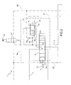
Figure 2 illustrates on an enlarged scale a detail of the hydraulic system offigure 1 . - In
Figure 1 , with number 1 is indicated, as a whole, a hydraulic system for actuating a plurality ofhydraulic actuators 2 for working machines (not shown). The hydraulic system 1 comprises a high-pressure oil delivery 3, adischarge return line 4 and a low-pressure oil discharge 5. - The hydraulic system 1 also comprises a plurality of distributors 6, each of which is associated with a
respective actuator 2 for adjusting the feeding modality of oil to theactuator 2 itself, as will be explained more fully below. - The hydraulic system 1 comprises a plurality of
controls 7, each of which regulates the operation of the respective distributor 6. Somedistributors 6a (only two of which are illustrated inFigure 1 ) are directly controlled by the user manually operating the respective control levers, each of which is mechanically connected to acorresponding control 7a.Other distributors 6b (only one of which is shown inFigure 1 ) are indirectly controlled by the user through the interposition of a hydraulic servo control 8; in this case, eachdistributor 6b comprises acontrol 7b hydraulically actuated by a hydraulic servo control 8. - As shown in
Figure 1 , each distributor 6 comprises amain slide valve 9, which is actuated by therespective control 7 and is provided with an axially sliding spool, and apressure compensator 10. - The
compensator 10 is hydraulically connected to themain slide valve 9, has amain inlet 11 connectable through themain slide valve 9 to the main delivery 3 and amain discharge 12 which is connectable by way of themain slide valve 9 to the correspondinghydraulic actuator 2. In addition, thecompensator 10 has afrontal chamber 13 which is permanently connected to thedelivery 11, and a rear chamber 14 which is connectable with thedischarge 5, as will be explained more fully below. - Note that each
distributor 6a actuated by acontrol 7a controlled by a manual control lever also comprises adrainage line 15, which connects thefront chamber 13 of thecompensator 10 to thedischarge 5 during a stand-by phase, as will be explained more fully below. - Each
distributor 6a actuated by acontrol 7a controlled by a manual control lever comprises a gaugedthrottle 19 arranged upstream of thefrontal chamber 13 between theinlet 11 and thedrainage line 15; the function of the gaugedthrottle 19 is to limit the amount of oil under pressure flowing towards theoutlet 5 through thedrainage line 15 to increase the overall energy efficiency. - Each
distributor 6a actuated by acontrol 7a controlled by a manual control lever also comprises a one-way valve 20 arranged along thedrainage line 15; the function of the one-way valve 20 is to prevent oil reflux and improves the functioning and actuation accuracy of thecompensator 10. - As shown in
Figure 1 , the hydraulic system 1 comprises a plurality ofdistributors 6a controlled by respective manual control levers and thefrontal chambers 13 ofrespective compensators 10 are connected through thecorresponding drainage lines 15 to the samecommon drainage line 16. The hydraulic system 1 also comprises adrainage valve 17 that is arranged along thecommon drainage line 16 and is adapt for opening or closing thecommon drainage line 16. - As shown in
Figure 1 , the hydraulic system 1 also comprises anactivation line 22, which is fed with oil at a pressure generally less than that of the oil which is present in the delivery 3 and is hydraulically connected to thedrainage valve 17 and to the servo control 8; and anactivation valve 23 that connects or isolates theactivation line 22 from the feeding of pressurized oil, thus regulating the opening or closing of thedrainage valve 17 and the activation of the servo control 8. - As illustrated, the hydraulic system 1 also comprises:
- a
signal line 21 connected to the rear chamber 14 of eachcompensator 10; - a
secondary drainage line 25 connected to thedischarge 5, and asafety slide valve 24 for each distributor 6. - The
safety slide valve 24 is integral with a respectivemain slide valve 9, is arranged along thesecondary drainage line 25, and is actuated by arespective control 7 for opening or closing thesecondary drainage line 25. All thesafety slide valves 24 are interconnected in series along thesecondary drainage line 25; eachsafety slide valve 24 does not interrupt thesecondary drainage line 25 when the correspondingmain slide valve 9 is held in a stand-by position while it interrupts thesecondary drainage line 25 when the correspondingmain slide valve 9 is arranged in a different position from the stand-by position. - As shown in
Figure 1 , thesecondary drainage line 25 connects anode 28 of thesignal line 21 to thedischarge 5. Thedrainage line 25 is connected to thesignal line 21 and in correspondence to thenode 28 upstream (with respect to the direction of oil circulation) of thesafety slide valves 24. In other words, thenode 28 is upstream, with respect to the direction of oil circulation in thedrainage line 25, of the safety slide valves 24.In this way, the hydraulic system 1 allows a faster discharge of thesignal line 21 with respect to known type hydraulic systems as thesignal line 21 is directly connected to thedrainage line 25, when all thesafety slide valves 24 are in the closed position (i.e. when all themain slide valves 9 are in the stand-by position). By saying that thedrainage line 25 is connected directly to thenode 28 of thesignal line 21 it means that thedrainage line 25 is connected to thenode 28 of thesignal line 21 without the interposition of any other device. - The hydraulic system 1 further comprises:
- a
pressure regulator 26 which is fed from the delivery 3 and is connected to thenode 28 of thesignal line 21; - a
pressure limiter 27, which is adapted for connecting thenode 28 of thesignal line 21 to thedischarge 5; - an
auxiliary drainage line 29 connecting thenode 28 of thesignal line 21 to thedischarge 5, and - an
auxiliary slide valve 30 which is electrically actuated and is interposed along theauxiliary drainage line 29 for opening or closing theauxiliary drainage line 29 itself. - According to that shown in
Figure 1 , the hydraulic system 1 comprises a plurality of distributors 6 grouped together in one body, so as to form a distribution block B (of a known type and schematically illustrated); the number of distributors 6 matches the number ofhydraulic actuators 2 fed by the hydraulic system 1. Typically, a mini-excavator is adapted for feeding from 9 to 12 actuators. Each distributor 6 has, in a known way and schematically illustrated, a plurality of connecting elements such as to allow the flow of oil from a distributor 6 to an adjacent one, as shown in the diagram ofFigure 1 . - Each
drainage line 15, thecommon drainage line 16, thesignal line 21 are made as control ducts (secondary) and illustrated by dashed lines; in other words, thedrainage line 15, thecommon drainage line 16 and thesignal line 21 present reduced sections and are adapt for the passage of a small amount of oil that is used to regulate the operation of thecompensators 10. While the delivery 3 is made as a power duct (primary) and adapted for transferring a flow of oil at sufficient pressure to actuate theactuators 2. - In use, the hydraulic system 1 for actuating a mini-excavator is fed with oil at a pressure between 190-240 bars; while, during a "standby" or idle phase (shown in
Figure 1 ), the oil pressure in the delivery 3 is maintained between 10-20 bar. - To prepare the hydraulic system 1 according to the stand-by configuration shown in
Figure 1 , theactivation valve 23 is de-energized (i.e., deprived of electrical power) and then arranged in a position in which it connects theactivation line 22 to thedischarge 5. In this condition, theactivation line 22 is devoid of hydraulic pressure being connected to thedischarge 5; as a result, the actuator 8 is not able to operate as it is lacking the necessary hydraulic pressure (and therefore any action exerted on the servo control 8 does not produce any effect on thecorresponding distributors 6b and, consequently, the corresponding hydraulic actuators 2). Furthermore, when theactivation line 22 is without hydraulic pressure, the hydraulically controlleddrainage valve 17 is arranged in the closed position (thedrainage valve 17 is normally closed) consequently determining the connection to thedischarge 5 of all thefrontal chambers 13 ofcompensators 10 ofdistributors 6a; therefore acting also upon thecontrols 7a ofdistributors 6a it is not possible to obtain any movement of the correspondinghydraulic actuators 2 since theirrespective compensators 10 are rendered completely inactive by the connection to thedischarge 5 of thefront chambers 13. In other words, in case of actuating (accidentally or intended) of acontrol 7a controlled by a manual control lever such as to bring the correspondingmain slide valve 9 in a working position and the hydraulic system 1 is in a stand-by mode, the pressurized oil sent from the delivery 3 to thefrontal chamber 13 of thecompensator 10 is diverted through thedrainage line 15 towards thedischarge 5. In this way the actuation of thecompensator 10 is inhibited, which remains in the stand-by position preventing the passage of oil to thecorresponding actuator 2. - As gathered from the above disclosure, the above described hydraulic system 1 allows the complete inhibition by way of less expensive regulatory elements of hydraulic type and of easy and fast deployment, of the actuation in the stand-by phase of an
actuator 2 actuated by acontrol 7a controlled by a manual control lever. - It is further seen that the implementation of a hydraulic system 1 in which the
signal line 21 is directly connected to thesecondary drainage line 25 increases the discharge and the reaction speed of the hydraulic system 1, as well as facilitating and speeding up production time and lowering production costs (fewer mechanical components to be employed in the hydraulic system and fewer finishing operations, such as lapping, to be undertaken). - Therefore, the hydraulic system 1 increases the security of a mini-excavator, ensuring the inhibition of each
actuator 2 in stand-by phase, avoiding the use of mechanical locking devices or complicated logic controls.
Claims (9)
- Hydraulic system for actuating the hydraulic actuators (2) of a working machine; the hydraulic system (1) comprises:a high-pressure oil delivery (3);a low-pressure oil discharge (5);at least one first slide valve (9) which comprises a first spool, which is axially slidable, and controls a first hydraulic actuator (2);a first control (7a) which can be directly actuated by an operator by means of a control lever and controls the position of the first spool of the first slide valve (9); anda first pressure compensator (10) which is hydraulically connected to the first slide valve (9), has a main inlet (11), which can be connected to the delivery (3) by means of the first slide valve (9), and a main outlet (12), which can be connected to the first hydraulic actuator (2) by means of the first slide valve (9), and presents a frontal chamber (13) which determines the control of the pressure compensator (10) and is permanently connected to the main inlet (11);the hydraulic system (1) being characterised in that it comprises:a first drainage line (15), which connects the frontal chamber (13) of the first pressure compensator (10) to the discharge (5) and is provided with a drainage valve (17) which is actuated in order to open or close the first drainage line (15);a signal line (21) which is connected to a rear chamber (14) of the first pressure compensator (10); wherein the signal line (21) has a node (28);a second drainage line (25) which connects the node (28) of the signal line (21) to the discharge (5); wherein the second drainage line (25) is connected directly to the signal line (21) in correspondence of said node (28); and,a second safety slide valve (24) comprising a second spool which is fixed to the first spool of the first slide valve (9), is axially sliding and is arranged along the second drainage line (25) in order to close or open the second drainage line (25) itself.
- Hydraulic system according to claim 1, and comprising an activation valve (23) which controls the position of the drainage valve (17).
- Hydraulic system according to claim 2, wherein:the drainage valve (17) is hydraulically actuated in function of the pressure of the oil in an activation line (22); andthe activation valve (23) selectively connects the activation line (22) to the discharge (5) or to an intermediate-pressure oil delivery (3).
- Hydraulic system according to claim 2 or 3, and comprising:a third slide valve (9) which comprises a third spool, which is axially slidable, and controls a second hydraulic actuator (2); anda hydraulic servo control (8) which controls the position of the third spool of the third slide valve (9) by means of a second control (7b) and is enabled and disabled by the action of the activation valve (23).
- Hydraulic system according to one of the claims from 1 to 4, and comprising a gauged throttler (19) which limits the flow rate of oil flowing through the first drainage line (15).
- Hydraulic system according to claim 5, wherein the gauged throttler (19) is arranged upstream of the frontal chamber (13) between the main inlet (11) of the first pressure compensator (10) and the first drainage line (15).
- Hydraulic system according to one of the claims from 1 to 6 and comprising a one-way valve (20) arranged along the first drainage line (15).
- Hydraulic system according to one of the claims from 1 to 7 and comprising:a plurality of first slide valves (9), each of which comprises a first spool, which is axially slidable, and controls a corresponding first hydraulic actuator (2);a plurality of controls (7a), each of which can be actuated by an operator by means of a respective control lever and directly controls the position of the first spool of a corresponding first slide valve (9); anda plurality of first pressure compensators (10), each of which is hydraulically connected to a corresponding first slide valve (9) and presents a frontal chamber (13) which is connected to a same first drainage line (15) common for all the first pressure compensators (10).
- Hydraulic distributor for a hydraulic system of the type claimed in one or more of the claims from 1 to 8.
Applications Claiming Priority (2)
| Application Number | Priority Date | Filing Date | Title |
|---|---|---|---|
| IT000358A ITBO20100358A1 (en) | 2010-06-08 | 2010-06-08 | HYDRAULIC PLANT AND HYDRAULIC DISTRIBUTOR FOR THE OPERATION OF OPERATING MACHINES |
| PCT/IB2011/001266 WO2011154809A1 (en) | 2010-06-08 | 2011-06-08 | Hydraulic system and hydraulic distributor for the actuating working machines |
Publications (2)
| Publication Number | Publication Date |
|---|---|
| EP2580483A1 EP2580483A1 (en) | 2013-04-17 |
| EP2580483B1 true EP2580483B1 (en) | 2015-12-30 |
Family
ID=43413539
Family Applications (1)
| Application Number | Title | Priority Date | Filing Date |
|---|---|---|---|
| EP11749504.4A Not-in-force EP2580483B1 (en) | 2010-06-08 | 2011-06-08 | Hydraulic system and hydraulic distributor for actuating working machines |
Country Status (5)
| Country | Link |
|---|---|
| US (1) | US9188286B2 (en) |
| EP (1) | EP2580483B1 (en) |
| CN (1) | CN103038518B (en) |
| IT (1) | ITBO20100358A1 (en) |
| WO (1) | WO2011154809A1 (en) |
Families Citing this family (3)
| Publication number | Priority date | Publication date | Assignee | Title |
|---|---|---|---|---|
| EP2918853B1 (en) | 2014-03-11 | 2016-03-09 | Bucher Hydraulics S.p.A. | Hydraulic section for load sensing applications and multiple hydraulic distributor |
| EP2980416B1 (en) | 2014-07-31 | 2019-06-05 | Bucher Hydraulics S.p.A. | Hydraulic section for load sensing applications and multiple hydraulic distributor |
| CN107555389B (en) * | 2017-08-29 | 2024-03-15 | 鼎纳科技有限公司 | Pneumatic liquid discharge device |
Family Cites Families (5)
| Publication number | Priority date | Publication date | Assignee | Title |
|---|---|---|---|---|
| IT1187892B (en) * | 1986-02-04 | 1987-12-23 | Chs Vickers Spa | HYDRAULIC CONTROL CIRCUIT FOR WORKING BODIES OF EARTH-MOVING MACHINES WITH CENTRALIZED ACTUATOR BRAKING |
| DE4036720C2 (en) * | 1990-11-17 | 2001-09-13 | Linde Ag | Control circuit for the load-independent distribution of a pressure medium flow |
| DK1860327T3 (en) * | 2006-05-26 | 2010-04-19 | Hydrocontrol S P A | Pressure compensating directional control valve |
| DE102006060333B3 (en) * | 2006-12-20 | 2008-08-21 | Sauer-Danfoss Aps | Hydraulic valve arrangement |
| DE102006060326B4 (en) * | 2006-12-20 | 2008-11-27 | Sauer-Danfoss Aps | Hydraulic valve arrangement |
-
2010
- 2010-06-08 IT IT000358A patent/ITBO20100358A1/en unknown
-
2011
- 2011-06-08 US US13/702,952 patent/US9188286B2/en not_active Expired - Fee Related
- 2011-06-08 EP EP11749504.4A patent/EP2580483B1/en not_active Not-in-force
- 2011-06-08 WO PCT/IB2011/001266 patent/WO2011154809A1/en not_active Ceased
- 2011-06-08 CN CN201180028386.1A patent/CN103038518B/en not_active Expired - Fee Related
Also Published As
| Publication number | Publication date |
|---|---|
| CN103038518A (en) | 2013-04-10 |
| WO2011154809A8 (en) | 2012-04-05 |
| US20130139918A1 (en) | 2013-06-06 |
| WO2011154809A1 (en) | 2011-12-15 |
| CN103038518B (en) | 2016-02-17 |
| EP2580483A1 (en) | 2013-04-17 |
| ITBO20100358A1 (en) | 2011-12-09 |
| US9188286B2 (en) | 2015-11-17 |
Similar Documents
| Publication | Publication Date | Title |
|---|---|---|
| KR100234605B1 (en) | Hydraulic control system having poppet and spool type valves | |
| EP2876306B1 (en) | Flow control valve for construction machinery | |
| CN102720710B (en) | Hydraulic system, control method of hydraulic system and construction machinery | |
| US9328842B2 (en) | Hydraulic actuating assembly | |
| US11692332B2 (en) | Hydraulic control system | |
| US8661809B2 (en) | Method for operating a hydraulic system, and hydraulic system | |
| EP2980416B1 (en) | Hydraulic section for load sensing applications and multiple hydraulic distributor | |
| CN101003977A (en) | Hydraulic control device for working machine | |
| CN102251996A (en) | Engineering mechanical load sensing hydraulic system | |
| WO2014135284A1 (en) | Merging circuit of hydraulic apparatus | |
| US9188286B2 (en) | Hydraulic system and hydraulic distributor for the actuating working machines | |
| EP2573407B1 (en) | Hydraulic control valve for construction machinery | |
| US9726203B2 (en) | Hydraulic control assembly | |
| CN108602527A (en) | The hydraulic steering of trouble-saving with reinforcement | |
| EP2258927B1 (en) | An aircraft fuel control and shut-down system | |
| EP2184495B1 (en) | Method for limiting the maximum power required by the hydraulic system of an earth-moving machine and directional control valve operating said method | |
| WO2011154810A1 (en) | Hydraulic system and hydraulic distributor for actuating working machines | |
| CN102562694B (en) | Load-sensing regulating type hydrostatic drive system | |
| EP3822492B1 (en) | Hydraulic circuit having a combined compensation and energy recovery function | |
| EP2518224B1 (en) | Pump control system for a construction machine | |
| CN215633164U (en) | Integrated overspeed protection device | |
| EP2933504B1 (en) | Hydraulic circuit for construction machines | |
| CN212428961U (en) | DEH system emergency interrupt control mechanism | |
| US20200340499A1 (en) | Control device | |
| US9695843B2 (en) | Hydraulic load-sensing control arrangement |
Legal Events
| Date | Code | Title | Description |
|---|---|---|---|
| PUAI | Public reference made under article 153(3) epc to a published international application that has entered the european phase |
Free format text: ORIGINAL CODE: 0009012 |
|
| 17P | Request for examination filed |
Effective date: 20121212 |
|
| AK | Designated contracting states |
Kind code of ref document: A1 Designated state(s): AL AT BE BG CH CY CZ DE DK EE ES FI FR GB GR HR HU IE IS IT LI LT LU LV MC MK MT NL NO PL PT RO RS SE SI SK SM TR |
|
| DAX | Request for extension of the european patent (deleted) | ||
| REG | Reference to a national code |
Ref country code: DE Ref legal event code: R079 Ref document number: 602011022276 Country of ref document: DE Free format text: PREVIOUS MAIN CLASS: F15B0011160000 Ipc: E02F0009220000 |
|
| RIC1 | Information provided on ipc code assigned before grant |
Ipc: F17D 1/00 20060101ALI20140828BHEP Ipc: E02F 3/32 20060101ALI20140828BHEP Ipc: F15B 11/16 20060101ALI20140828BHEP Ipc: E02F 9/22 20060101AFI20140828BHEP |
|
| 17Q | First examination report despatched |
Effective date: 20140924 |
|
| GRAP | Despatch of communication of intention to grant a patent |
Free format text: ORIGINAL CODE: EPIDOSNIGR1 |
|
| INTG | Intention to grant announced |
Effective date: 20150626 |
|
| GRAS | Grant fee paid |
Free format text: ORIGINAL CODE: EPIDOSNIGR3 |
|
| GRAA | (expected) grant |
Free format text: ORIGINAL CODE: 0009210 |
|
| AK | Designated contracting states |
Kind code of ref document: B1 Designated state(s): AL AT BE BG CH CY CZ DE DK EE ES FI FR GB GR HR HU IE IS IT LI LT LU LV MC MK MT NL NO PL PT RO RS SE SI SK SM TR |
|
| REG | Reference to a national code |
Ref country code: GB Ref legal event code: FG4D |
|
| REG | Reference to a national code |
Ref country code: CH Ref legal event code: EP |
|
| REG | Reference to a national code |
Ref country code: AT Ref legal event code: REF Ref document number: 767566 Country of ref document: AT Kind code of ref document: T Effective date: 20160115 |
|
| REG | Reference to a national code |
Ref country code: IE Ref legal event code: FG4D |
|
| REG | Reference to a national code |
Ref country code: DE Ref legal event code: R096 Ref document number: 602011022276 Country of ref document: DE |
|
| REG | Reference to a national code |
Ref country code: LT Ref legal event code: MG4D |
|
| PG25 | Lapsed in a contracting state [announced via postgrant information from national office to epo] |
Ref country code: NO Free format text: LAPSE BECAUSE OF FAILURE TO SUBMIT A TRANSLATION OF THE DESCRIPTION OR TO PAY THE FEE WITHIN THE PRESCRIBED TIME-LIMIT Effective date: 20160330 Ref country code: LT Free format text: LAPSE BECAUSE OF FAILURE TO SUBMIT A TRANSLATION OF THE DESCRIPTION OR TO PAY THE FEE WITHIN THE PRESCRIBED TIME-LIMIT Effective date: 20151230 Ref country code: HR Free format text: LAPSE BECAUSE OF FAILURE TO SUBMIT A TRANSLATION OF THE DESCRIPTION OR TO PAY THE FEE WITHIN THE PRESCRIBED TIME-LIMIT Effective date: 20151230 |
|
| REG | Reference to a national code |
Ref country code: NL Ref legal event code: MP Effective date: 20151230 |
|
| REG | Reference to a national code |
Ref country code: AT Ref legal event code: MK05 Ref document number: 767566 Country of ref document: AT Kind code of ref document: T Effective date: 20151230 |
|
| REG | Reference to a national code |
Ref country code: FR Ref legal event code: PLFP Year of fee payment: 6 |
|
| PG25 | Lapsed in a contracting state [announced via postgrant information from national office to epo] |
Ref country code: FI Free format text: LAPSE BECAUSE OF FAILURE TO SUBMIT A TRANSLATION OF THE DESCRIPTION OR TO PAY THE FEE WITHIN THE PRESCRIBED TIME-LIMIT Effective date: 20151230 Ref country code: SE Free format text: LAPSE BECAUSE OF FAILURE TO SUBMIT A TRANSLATION OF THE DESCRIPTION OR TO PAY THE FEE WITHIN THE PRESCRIBED TIME-LIMIT Effective date: 20151230 Ref country code: GR Free format text: LAPSE BECAUSE OF FAILURE TO SUBMIT A TRANSLATION OF THE DESCRIPTION OR TO PAY THE FEE WITHIN THE PRESCRIBED TIME-LIMIT Effective date: 20160331 Ref country code: LV Free format text: LAPSE BECAUSE OF FAILURE TO SUBMIT A TRANSLATION OF THE DESCRIPTION OR TO PAY THE FEE WITHIN THE PRESCRIBED TIME-LIMIT Effective date: 20151230 Ref country code: RS Free format text: LAPSE BECAUSE OF FAILURE TO SUBMIT A TRANSLATION OF THE DESCRIPTION OR TO PAY THE FEE WITHIN THE PRESCRIBED TIME-LIMIT Effective date: 20151230 |
|
| PG25 | Lapsed in a contracting state [announced via postgrant information from national office to epo] |
Ref country code: NL Free format text: LAPSE BECAUSE OF FAILURE TO SUBMIT A TRANSLATION OF THE DESCRIPTION OR TO PAY THE FEE WITHIN THE PRESCRIBED TIME-LIMIT Effective date: 20151230 |
|
| PG25 | Lapsed in a contracting state [announced via postgrant information from national office to epo] |
Ref country code: ES Free format text: LAPSE BECAUSE OF FAILURE TO SUBMIT A TRANSLATION OF THE DESCRIPTION OR TO PAY THE FEE WITHIN THE PRESCRIBED TIME-LIMIT Effective date: 20151230 Ref country code: CZ Free format text: LAPSE BECAUSE OF FAILURE TO SUBMIT A TRANSLATION OF THE DESCRIPTION OR TO PAY THE FEE WITHIN THE PRESCRIBED TIME-LIMIT Effective date: 20151230 |
|
| PG25 | Lapsed in a contracting state [announced via postgrant information from national office to epo] |
Ref country code: SK Free format text: LAPSE BECAUSE OF FAILURE TO SUBMIT A TRANSLATION OF THE DESCRIPTION OR TO PAY THE FEE WITHIN THE PRESCRIBED TIME-LIMIT Effective date: 20151230 Ref country code: PL Free format text: LAPSE BECAUSE OF FAILURE TO SUBMIT A TRANSLATION OF THE DESCRIPTION OR TO PAY THE FEE WITHIN THE PRESCRIBED TIME-LIMIT Effective date: 20151230 Ref country code: SM Free format text: LAPSE BECAUSE OF FAILURE TO SUBMIT A TRANSLATION OF THE DESCRIPTION OR TO PAY THE FEE WITHIN THE PRESCRIBED TIME-LIMIT Effective date: 20151230 Ref country code: PT Free format text: LAPSE BECAUSE OF FAILURE TO SUBMIT A TRANSLATION OF THE DESCRIPTION OR TO PAY THE FEE WITHIN THE PRESCRIBED TIME-LIMIT Effective date: 20160502 Ref country code: IS Free format text: LAPSE BECAUSE OF FAILURE TO SUBMIT A TRANSLATION OF THE DESCRIPTION OR TO PAY THE FEE WITHIN THE PRESCRIBED TIME-LIMIT Effective date: 20160430 Ref country code: RO Free format text: LAPSE BECAUSE OF FAILURE TO SUBMIT A TRANSLATION OF THE DESCRIPTION OR TO PAY THE FEE WITHIN THE PRESCRIBED TIME-LIMIT Effective date: 20151230 Ref country code: EE Free format text: LAPSE BECAUSE OF FAILURE TO SUBMIT A TRANSLATION OF THE DESCRIPTION OR TO PAY THE FEE WITHIN THE PRESCRIBED TIME-LIMIT Effective date: 20151230 Ref country code: AT Free format text: LAPSE BECAUSE OF FAILURE TO SUBMIT A TRANSLATION OF THE DESCRIPTION OR TO PAY THE FEE WITHIN THE PRESCRIBED TIME-LIMIT Effective date: 20151230 |
|
| REG | Reference to a national code |
Ref country code: DE Ref legal event code: R097 Ref document number: 602011022276 Country of ref document: DE |
|
| PG25 | Lapsed in a contracting state [announced via postgrant information from national office to epo] |
Ref country code: DK Free format text: LAPSE BECAUSE OF FAILURE TO SUBMIT A TRANSLATION OF THE DESCRIPTION OR TO PAY THE FEE WITHIN THE PRESCRIBED TIME-LIMIT Effective date: 20151230 |
|
| PLBE | No opposition filed within time limit |
Free format text: ORIGINAL CODE: 0009261 |
|
| STAA | Information on the status of an ep patent application or granted ep patent |
Free format text: STATUS: NO OPPOSITION FILED WITHIN TIME LIMIT |
|
| 26N | No opposition filed |
Effective date: 20161003 |
|
| PG25 | Lapsed in a contracting state [announced via postgrant information from national office to epo] |
Ref country code: BE Free format text: LAPSE BECAUSE OF FAILURE TO SUBMIT A TRANSLATION OF THE DESCRIPTION OR TO PAY THE FEE WITHIN THE PRESCRIBED TIME-LIMIT Effective date: 20151230 |
|
| PG25 | Lapsed in a contracting state [announced via postgrant information from national office to epo] |
Ref country code: MC Free format text: LAPSE BECAUSE OF FAILURE TO SUBMIT A TRANSLATION OF THE DESCRIPTION OR TO PAY THE FEE WITHIN THE PRESCRIBED TIME-LIMIT Effective date: 20151230 |
|
| REG | Reference to a national code |
Ref country code: CH Ref legal event code: PL |
|
| PG25 | Lapsed in a contracting state [announced via postgrant information from national office to epo] |
Ref country code: SI Free format text: LAPSE BECAUSE OF FAILURE TO SUBMIT A TRANSLATION OF THE DESCRIPTION OR TO PAY THE FEE WITHIN THE PRESCRIBED TIME-LIMIT Effective date: 20151230 |
|
| REG | Reference to a national code |
Ref country code: IE Ref legal event code: MM4A |
|
| PG25 | Lapsed in a contracting state [announced via postgrant information from national office to epo] |
Ref country code: CH Free format text: LAPSE BECAUSE OF NON-PAYMENT OF DUE FEES Effective date: 20160630 Ref country code: LI Free format text: LAPSE BECAUSE OF NON-PAYMENT OF DUE FEES Effective date: 20160630 |
|
| PG25 | Lapsed in a contracting state [announced via postgrant information from national office to epo] |
Ref country code: IE Free format text: LAPSE BECAUSE OF NON-PAYMENT OF DUE FEES Effective date: 20160608 |
|
| REG | Reference to a national code |
Ref country code: FR Ref legal event code: PLFP Year of fee payment: 7 |
|
| REG | Reference to a national code |
Ref country code: FR Ref legal event code: CD Owner name: WALVOIL S.P.A., IT Effective date: 20180111 Ref country code: FR Ref legal event code: CJ Effective date: 20180111 Ref country code: FR Ref legal event code: TP Owner name: WALVOIL S.P.A., IT Effective date: 20180111 |
|
| PG25 | Lapsed in a contracting state [announced via postgrant information from national office to epo] |
Ref country code: HU Free format text: LAPSE BECAUSE OF FAILURE TO SUBMIT A TRANSLATION OF THE DESCRIPTION OR TO PAY THE FEE WITHIN THE PRESCRIBED TIME-LIMIT; INVALID AB INITIO Effective date: 20110608 Ref country code: CY Free format text: LAPSE BECAUSE OF FAILURE TO SUBMIT A TRANSLATION OF THE DESCRIPTION OR TO PAY THE FEE WITHIN THE PRESCRIBED TIME-LIMIT Effective date: 20151230 |
|
| REG | Reference to a national code |
Ref country code: FR Ref legal event code: PLFP Year of fee payment: 8 |
|
| PG25 | Lapsed in a contracting state [announced via postgrant information from national office to epo] |
Ref country code: LU Free format text: LAPSE BECAUSE OF NON-PAYMENT OF DUE FEES Effective date: 20160608 Ref country code: MK Free format text: LAPSE BECAUSE OF FAILURE TO SUBMIT A TRANSLATION OF THE DESCRIPTION OR TO PAY THE FEE WITHIN THE PRESCRIBED TIME-LIMIT Effective date: 20151230 Ref country code: MT Free format text: LAPSE BECAUSE OF NON-PAYMENT OF DUE FEES Effective date: 20160630 Ref country code: TR Free format text: LAPSE BECAUSE OF FAILURE TO SUBMIT A TRANSLATION OF THE DESCRIPTION OR TO PAY THE FEE WITHIN THE PRESCRIBED TIME-LIMIT Effective date: 20151230 |
|
| PG25 | Lapsed in a contracting state [announced via postgrant information from national office to epo] |
Ref country code: BG Free format text: LAPSE BECAUSE OF FAILURE TO SUBMIT A TRANSLATION OF THE DESCRIPTION OR TO PAY THE FEE WITHIN THE PRESCRIBED TIME-LIMIT Effective date: 20151230 |
|
| PG25 | Lapsed in a contracting state [announced via postgrant information from national office to epo] |
Ref country code: AL Free format text: LAPSE BECAUSE OF FAILURE TO SUBMIT A TRANSLATION OF THE DESCRIPTION OR TO PAY THE FEE WITHIN THE PRESCRIBED TIME-LIMIT Effective date: 20151230 |
|
| PGFP | Annual fee paid to national office [announced via postgrant information from national office to epo] |
Ref country code: FR Payment date: 20200619 Year of fee payment: 10 |
|
| PGFP | Annual fee paid to national office [announced via postgrant information from national office to epo] |
Ref country code: GB Payment date: 20200625 Year of fee payment: 10 |
|
| PGFP | Annual fee paid to national office [announced via postgrant information from national office to epo] |
Ref country code: IT Payment date: 20200630 Year of fee payment: 10 |
|
| GBPC | Gb: european patent ceased through non-payment of renewal fee |
Effective date: 20210608 |
|
| PG25 | Lapsed in a contracting state [announced via postgrant information from national office to epo] |
Ref country code: GB Free format text: LAPSE BECAUSE OF NON-PAYMENT OF DUE FEES Effective date: 20210608 |
|
| PG25 | Lapsed in a contracting state [announced via postgrant information from national office to epo] |
Ref country code: FR Free format text: LAPSE BECAUSE OF NON-PAYMENT OF DUE FEES Effective date: 20210630 |
|
| PG25 | Lapsed in a contracting state [announced via postgrant information from national office to epo] |
Ref country code: IT Free format text: LAPSE BECAUSE OF NON-PAYMENT OF DUE FEES Effective date: 20210608 |
|
| PGFP | Annual fee paid to national office [announced via postgrant information from national office to epo] |
Ref country code: DE Payment date: 20230620 Year of fee payment: 13 |
|
| REG | Reference to a national code |
Ref country code: DE Ref legal event code: R119 Ref document number: 602011022276 Country of ref document: DE |
|
| PG25 | Lapsed in a contracting state [announced via postgrant information from national office to epo] |
Ref country code: DE Free format text: LAPSE BECAUSE OF NON-PAYMENT OF DUE FEES Effective date: 20250101 |