EP2580429B1 - Blade for a turbo machine - Google Patents
Blade for a turbo machine Download PDFInfo
- Publication number
- EP2580429B1 EP2580429B1 EP11745752.3A EP11745752A EP2580429B1 EP 2580429 B1 EP2580429 B1 EP 2580429B1 EP 11745752 A EP11745752 A EP 11745752A EP 2580429 B1 EP2580429 B1 EP 2580429B1
- Authority
- EP
- European Patent Office
- Prior art keywords
- blade
- platform
- nozzle
- turbomachine
- root portion
- Prior art date
- Legal status (The legal status is an assumption and is not a legal conclusion. Google has not performed a legal analysis and makes no representation as to the accuracy of the status listed.)
- Not-in-force
Links
- 238000001816 cooling Methods 0.000 claims description 77
- 239000012530 fluid Substances 0.000 claims description 10
- 238000007789 sealing Methods 0.000 claims description 10
- 238000011144 upstream manufacturing Methods 0.000 claims description 6
- IHQKEDIOMGYHEB-UHFFFAOYSA-M sodium dimethylarsinate Chemical class [Na+].C[As](C)([O-])=O IHQKEDIOMGYHEB-UHFFFAOYSA-M 0.000 claims description 5
- 238000013461 design Methods 0.000 description 4
- 230000000694 effects Effects 0.000 description 4
- PXHVJJICTQNCMI-UHFFFAOYSA-N Nickel Chemical compound [Ni] PXHVJJICTQNCMI-UHFFFAOYSA-N 0.000 description 2
- 230000001133 acceleration Effects 0.000 description 2
- 238000000034 method Methods 0.000 description 2
- 238000005275 alloying Methods 0.000 description 1
- WYTGDNHDOZPMIW-RCBQFDQVSA-N alstonine Natural products C1=CC2=C3C=CC=CC3=NC2=C2N1C[C@H]1[C@H](C)OC=C(C(=O)OC)[C@H]1C2 WYTGDNHDOZPMIW-RCBQFDQVSA-N 0.000 description 1
- 238000005266 casting Methods 0.000 description 1
- 238000004891 communication Methods 0.000 description 1
- 238000005260 corrosion Methods 0.000 description 1
- 230000007797 corrosion Effects 0.000 description 1
- 230000001419 dependent effect Effects 0.000 description 1
- 238000011161 development Methods 0.000 description 1
- 230000018109 developmental process Effects 0.000 description 1
- 239000000463 material Substances 0.000 description 1
- 239000002184 metal Substances 0.000 description 1
- 229910052751 metal Inorganic materials 0.000 description 1
- 238000012986 modification Methods 0.000 description 1
- 230000004048 modification Effects 0.000 description 1
- 229910052759 nickel Inorganic materials 0.000 description 1
- 230000003647 oxidation Effects 0.000 description 1
- 238000007254 oxidation reaction Methods 0.000 description 1
- 230000003068 static effect Effects 0.000 description 1
Images

Classifications
-
- F—MECHANICAL ENGINEERING; LIGHTING; HEATING; WEAPONS; BLASTING
- F01—MACHINES OR ENGINES IN GENERAL; ENGINE PLANTS IN GENERAL; STEAM ENGINES
- F01D—NON-POSITIVE DISPLACEMENT MACHINES OR ENGINES, e.g. STEAM TURBINES
- F01D25/00—Component parts, details, or accessories, not provided for in, or of interest apart from, other groups
- F01D25/08—Cooling; Heating; Heat-insulation
- F01D25/12—Cooling
-
- F—MECHANICAL ENGINEERING; LIGHTING; HEATING; WEAPONS; BLASTING
- F01—MACHINES OR ENGINES IN GENERAL; ENGINE PLANTS IN GENERAL; STEAM ENGINES
- F01D—NON-POSITIVE DISPLACEMENT MACHINES OR ENGINES, e.g. STEAM TURBINES
- F01D5/00—Blades; Blade-carrying members; Heating, heat-insulating, cooling or antivibration means on the blades or the members
- F01D5/02—Blade-carrying members, e.g. rotors
- F01D5/08—Heating, heat-insulating or cooling means
- F01D5/081—Cooling fluid being directed on the side of the rotor disc or at the roots of the blades
- F01D5/082—Cooling fluid being directed on the side of the rotor disc or at the roots of the blades on the side of the rotor disc
-
- F—MECHANICAL ENGINEERING; LIGHTING; HEATING; WEAPONS; BLASTING
- F01—MACHINES OR ENGINES IN GENERAL; ENGINE PLANTS IN GENERAL; STEAM ENGINES
- F01D—NON-POSITIVE DISPLACEMENT MACHINES OR ENGINES, e.g. STEAM TURBINES
- F01D11/00—Preventing or minimising internal leakage of working-fluid, e.g. between stages
- F01D11/02—Preventing or minimising internal leakage of working-fluid, e.g. between stages by non-contact sealings, e.g. of labyrinth type
- F01D11/04—Preventing or minimising internal leakage of working-fluid, e.g. between stages by non-contact sealings, e.g. of labyrinth type using sealing fluid, e.g. steam
-
- F—MECHANICAL ENGINEERING; LIGHTING; HEATING; WEAPONS; BLASTING
- F01—MACHINES OR ENGINES IN GENERAL; ENGINE PLANTS IN GENERAL; STEAM ENGINES
- F01D—NON-POSITIVE DISPLACEMENT MACHINES OR ENGINES, e.g. STEAM TURBINES
- F01D5/00—Blades; Blade-carrying members; Heating, heat-insulating, cooling or antivibration means on the blades or the members
- F01D5/12—Blades
- F01D5/14—Form or construction
- F01D5/18—Hollow blades, i.e. blades with cooling or heating channels or cavities; Heating, heat-insulating or cooling means on blades
- F01D5/187—Convection cooling
-
- F—MECHANICAL ENGINEERING; LIGHTING; HEATING; WEAPONS; BLASTING
- F05—INDEXING SCHEMES RELATING TO ENGINES OR PUMPS IN VARIOUS SUBCLASSES OF CLASSES F01-F04
- F05D—INDEXING SCHEME FOR ASPECTS RELATING TO NON-POSITIVE-DISPLACEMENT MACHINES OR ENGINES, GAS-TURBINES OR JET-PROPULSION PLANTS
- F05D2240/00—Components
- F05D2240/80—Platforms for stationary or moving blades
- F05D2240/81—Cooled platforms
-
- F—MECHANICAL ENGINEERING; LIGHTING; HEATING; WEAPONS; BLASTING
- F05—INDEXING SCHEMES RELATING TO ENGINES OR PUMPS IN VARIOUS SUBCLASSES OF CLASSES F01-F04
- F05D—INDEXING SCHEME FOR ASPECTS RELATING TO NON-POSITIVE-DISPLACEMENT MACHINES OR ENGINES, GAS-TURBINES OR JET-PROPULSION PLANTS
- F05D2260/00—Function
- F05D2260/20—Heat transfer, e.g. cooling
- F05D2260/201—Heat transfer, e.g. cooling by impingement of a fluid
Definitions
- the invention relates to a blade for a turbomachine, particularly a gas turbine, the blade particularly being arranged on a turbine rotor of the gas turbine. Furthermore, the invention relates to a turbomachine with a blade.
- Gas turbines known in the state of the art comprise a compressor, possibly divided in a low pressure compressor and a high pressure compressor. Furthermore, gas turbines have a combustor, where gas is mixed with compressed air. After exiting the combustor, the high energy gas stream then expands through the turbine, where energy is extracted to operate the compressor and produce mechanical work i.e. a torque.
- the pressure turbine is usually divided into a high pressure turbine and a low pressure turbine, wherein the high pressure turbine can include more than one stage as well as the low pressure turbine includes typically several stages.
- Each stage typically includes a rotor and a stator.
- the rotor disc also referred to as the turbine rotor, rotates about a centre line axis or a longitudinal axis of the gas turbine.
- typical blades comprise a cooling system with a cooling air supply passage in a root portion of the blade. Cooling air is supplied to holes of an airfoil of the blade to cool the surface of the airfoil by creating a cooling film.
- a stator is typically arranged upstream of the rotor.
- the stator comprises guide vanes.
- the guide vanes also referred to as nozzle guide vanes, NGV, are static vanes for guiding the expending gas stream onto the airfoils of the blades of the rotor.
- the nozzle guide vanes as well as the blades comprise platforms forming a labyrinth-sealing.
- Typical cooling methods for these extreme regions of NGV-platforms include impingement jets to the underside of the platform.
- European patent application EP1 178 181 A2 shows a system for cooling the platform of a blade. Similar techniques can be used for cooling the platform of a nozzle guide vane. From European patent application EP 1 205 634 A2 it is known to embody a platform of a blade with a hollow cavity in fluid communication with a cooling air channel. The cavity is further provided with straight outlet holes directed to an adjacent band of a vane for cooling the latter. US patent application US 2009/0232660 A1 describes to provide a platform of a blade with internal cooling passages for cooling of the platform. These passages extend from cooling channels in a root of the blade to sides of the root and are arranged inclined and downward in respect to a longitudinal direction of the blade. However, the jets produced by such arrangements are not able to reach the extreme edge of the platform due to mechanical and seal features at these locations.
- a blade for a turbomachine according to claim 1, particularly a gas turbine is provided, the blade particularly being arrangeable or arranged on a turbine rotor of the gas turbine.
- the blade is comprising a root portion having two narrow sides and two broad sides, a cooling air supply passage in the root portion, and a cooling air bleed being arranged in the root portion and being in fluid connection with the cooling air supply passage.
- the cooling air bleed comprises a nozzle on one of the narrow sides of the root portion.
- Typical embodiments of the invention comprise a nozzle on one of the narrow sides of the root portion.
- the narrow sides of the root portion are the two sides of the root portion, which are substantially perpendicular to the direction of flow of the hot gas stream in the gas turbine.
- the two narrow sides of the root portion are at least substantially perpendicular to the axis of rotation of the turbine rotor carrying the blades.
- the two narrow sides are the sides on both axial ends of the root portion, i.e. the upstream side and the downstream side in regards of a main fluid path of the turbomachine.
- the nozzle is formed by a hole.
- An axial direction of the hole - i.e. an axial component of a vector of orientation of the hole - is inclined upward between 92° and 135° with respect to the longitudinal direction of the blade.
- Other possible lower limits could be 95°, 100°, 110°, or 120°.
- Other possible upper limits could be 110°, 120°, or 130°.
- “Upwards” means in direction of the main flow path or away from the axis of rotation of the gas turbine rotor. In other words, upwards means a direction from a blade root to the blade airfoil.
- the hole is a fluid passage
- the fluid passage is oriented with an axial component - parallel to the rotating axis of the turbomachine -, a radial component - perpendicular to the rotating axis of the turbomachine - and a circumferential component - perpendicular to the axial and radial components.
- inclined upwards means that the passage has a radial component away from the rotating axis, the radial component is not equal to zero.
- the axial component is opposite to the main fluid flow within the turbomachine, the axial component is not equal to zero.
- the circumferential direction may be zero or may be also not equal to zero.
- the hole - i.e. the fluid passage - may be formed substantially cylindrical.
- the advantage of the nozzle is that cooling air is directed to an edge of the platform region of the nozzle guide vane, assuming the blade is assembled in the turbomachine and the turbomachine is operating. This is particularly advantageous for a direct cooling of the extreme edge of the platform region of the nozzle guide vane.
- the trailing edge of the nozzle guide vane may be cooled of an adjacent nozzle guide vane, which is located upstream of the blade.
- An extreme edge of the platform region of the nozzle guide vane is intended to mean a rim, a tip, a nose, a cone end and/or a lip of the platform region of the nozzle guide vane that is directed towards the blade. It should be noted that the two broad sides of the blade are advantageously formed like a dove tail or a fir tree for a secure fixation of the blade in the rotor disc of the turbine rotor.
- the nozzle is formed by a hole machined in the root portion.
- the hole is advantageously oval, in particular circular. This avoids notch stresses.
- an axial direction of the hole is directed at least partially in a longitudinal direction of the blade.
- the longitudinal direction of the blade can also be referred to as the radial direction of the turbine rotor.
- the axial direction of the hole is inclined between 92° and 135°, especially more than 95° or less than 120°, with respect to the longitudinal direction of the blade. Such an alignment of the hole promotes a better cooling of the edge of the platform region of the nozzle guide vane.
- the axial direction of the hole lies at least essentially in a plane, the plane being orientated radial with respect to the axis of rotation of the turbine rotor.
- the jet of cooling air will reach the guide vanes at an angle with the axis of the hole lying in the mentioned plane.
- typical embodiments comprise a hole with an axial direction being inclined with respect to a radial plane of the turbine rotor. If the resulting direction of the cooling air jet is in the same direction as the rotation of the blade the cooling effect will be the highest. If the resulting direction of the jet is in the opposite direction as the rotation of the blade the jet will generate a torque i.e. improving the efficiency but provide reduced cooling.
- Preferred turbine rotors comprise blades having holes which axial directions are different with respect to a radial plane of the rotating axis of the turbine rotor.
- the blade comprises an upper blade platform - in direction of the airfoil - and a lower blade platform - in direction of the blade root -, wherein the nozzle is arranged between the upper blade platform and the lower blade platform.
- This arrangement avoids the handicap that a cooling air stream for the edge of the platform region is hindered by the labyrinth seal of the platforms.
- the seal is conventionally formed by the platforms, such that a cooling air bleed between the platforms serves for a better cooling of parts in between the seal.
- the nozzle is placed below the upper platform or above the lower platform.
- inventions have a nozzle below the lower platform or above the upper platform.
- embodiments having a nozzle formed within a platform of the blade can provide a better cooling of the platform region of the nozzle guide vanes.
- Preferred embodiments provide a plurality of nozzles, e.g. two, three or even more nozzles, positioned at the above mentioned positions. A plurality of nozzles may provide better cooling.
- the location of the nozzle depends on the design and stress distribution of the blade root region, the design of the nozzle guide vane platform, the amount of hot gas ingress into the cavity or whether platform region needs cooling.
- the nozzle or the hole is arranged on a front surface of the root portion.
- the front surface of the root portion is the surface being aligned perpendicular to the axis of rotation of the rotor disc of the turbine rotor.
- the front surface may be particularly an upstream surface.
- Particular realizations comprise a plurality of nozzles on one of the narrow sides of the root portion.
- the plurality of nozzles has the advantage, that more cooling air can be guided to the platform region of the nozzle guide vane. Furthermore, more nozzles can be used to reduce the diameter of one of the holes of the nozzle. This serves for a better strength of the blade.
- a further aspect of the invention is related to a turbo machine comprising a turbine rotor with at least one blade according to the above described realizations.
- a turbo machine has the advantage that a platform region of the nozzle guide vane is cooled by the cooling air from the holes in the root portion of the blade.
- the invention has the advantages that a high amount of cooling air to the extreme edges of the inner platform region of a nozzle guide vane is provided.
- the invention provides a better cooling than jets to the underside of the platform.
- the invention is better than methods using convection cooling which only provide a moderate amount of cooling.
- the rotation of the blade on the turbine rotor increases the cooling air pressure, so increasing the impingement effect of the jets, and also distribute the cooling air to the circumferential positions of the non-gas washed surface at the extreme front and rear of the inner platform.
- both narrow sides comprise a plurality of nozzles. This has the advantage that platform regions of the nozzle guide vanes on both sides of the turbine rotor can be cooled.
- Fig. 1 shows in a partly sectional view parts of a stationary gas turbine. Especially, a blade 1 is shown.
- the blade 1 comprises a root portion.
- the root portion is the area under a dotted line 2 in fig. 1 .
- the root portion has four side walls, also referred to as sides, namely two narrow sides 4 and 5 and two broad sides, which are parallel to the plane of projection of fig. 1 .
- the blade 1 comprises an airfoil which is depicted in fig. 1 above the dotted line 2.
- the airfoil of blade 1 is arranged in a channel for a stream of hot gas 7 - a main flow path of working fluid.
- the hot gas 7 is directed over the airfoil of the blade 1 to extract energy from the hot gas 7 for rotating a turbine rotor.
- the blade 1 is arranged on the turbine rotor (not shown).
- a nozzle guide vane 9 (NGV) is arranged upstream of the airfoil of the blade 1.
- the nozzle guide vane 9 provides a constant and directed stream of hot gas 7 to rotating airfoils like the airfoil of blade 1. It should be noted that during rotation of the turbine rotor airfoils of several blades pass the nozzle guide vane 9.
- a plurality of nozzle guide vanes 9 are arranged for directing the flow of hot gas 7.
- the blade 1 is typically a unitary casting of high strength metal containing high amounts of alloying elements such as nickel.
- the blade 1 is suitable for withstanding the high temperature of the hot gas 7 during operation. Additionally the material forming the blade 1 is suitable for high stresses in combination with high temperatures. This is due to the fact that during rotation of the turbine rotor, the blade 1 is subject to high forces.
- a cooling system should be provided for cooling at least some regions of the blade 1 during operation.
- a cooling air supply passage 10 is arranged in the root portion of the blade 1.
- the cooling air supply passage 10 serves for guiding cooling air into a serpentine cooler 11 which is arranged inside of the airfoil of the blade 1.
- airfoil of the blade 1 comprises openings for directing cooling air to the surface of the airfoil of the blade 1.
- the preferred embodiment shown in fig. 1 comprises an additional cooling air bleed 13 being arranged in the root portion and being in fluid connection with the cooling air supply passage 10.
- the cooling air bleed 13 comprises a nozzle 14 on the narrow side 4 of the root portion of the blade 1.
- the nozzle 14 is formed by a hole machined in the root portion.
- the axial direction of the hole of the nozzle 14 is directed at least partially in a longitudinal direction of the blade 1.
- the longitudinal direction of the blade 1 is a radial direction with respect to the rotating turbine rotor on which the blade 1 is fixed.
- the hole of the nozzle 14 is directed slightly upwards.
- Upwards means in direction of the main flow path or away from the axis of rotation of the gas turbine rotor.
- upwards means a direction from a blade root to the blade airfoil.
- the angle with respect to the longitudinal axis of the blade 1 is between 100° and 115°. Such an angle ensures that the cooling air jet through nozzle 14 is accelerated by the rotation of the turbine rotor.
- the bleed 13 or the axial direction of the hole of the nozzle 14 of the bleed 13, respectively, is inclined in respect to a direction of a main flow path or the stream of the hot gas 7.
- the cooling air leaving the nozzle 14 impinges directly the extreme edges of platform region 17 and 18 of the nozzle guide vane. Therefore, cooling of the extreme edges of the platform regions 17 and 18 of the nozzle guide vane is ensured.
- the acceleration of the cooling air due to the rotation of the turbine rotor further enhances the cooling effect of the cooling air impinging the platforms of the nozzle guide vanes.
- platform regions 17 and 18 together with an upper blade platform 20 of the blade 1 and a lower blade platform 21 of the blade 1 form a labyrinth-sealing.
- the labyrinth-sealing separates the inner regions of the gas turbine from the channel filled with the hot gas 7.
- the inner regions of the gas turbine are flooded with cooling air.
- convection cooling with cooling air from the inner region of the gas turbine may not be enough, at least in some situations.
- the invention with the jet of cooling air through the nozzle 14 has the advantage of a better cooling of platform regions 17 and 18.
- Cooling air will be directed via the cooling air bleed 13 towards a rim and/or a tip 24 of the platform region 18, the rim and/or the tip 24 being part of the labyrinth-sealing and directed towards the blade. Cooling air may hit the rim and/or the tip 24 and an upper surface of platform region 18, optionally also a lower surface of platform region 18.
- a further platform region 23 of a downstream nozzle guide vane is arranged on the downstream side of blade 1.
- the further platform region 23 can be cooled when necessary with an additional cooling air bleed.
- Such an additional cooling air bleed comprises a further nozzle between the upper blade platform 20 and the lower blade platform 21 on the downstream narrow side 5 of blade 1.
- the further nozzle provides a machined hole as well as the nozzle directed on the platform regions 17 and 18. Again, a hole with an inclined angle provides the advantage of a further acceleration of the cooling air.
- fig. 2 a schematic view of blade 1 is depicted. It should be noted that same parts in fig. 2 have same reference signs as in fig. 1 . For the sake of clearness, these parts are not been described again.
- the nozzle 14 with its machined hole on the narrow side 4 of the blade 1 is shown.
- the hole is arranged between the upper blade platform 20 and the lower blade platform 21.
- the broad sides of the root region of the blade 1 are formed like a dovetail to ensure a secure fixing of the blade 1 in the rotor disc of the turbine rotor (rotor disc not shown in the figures).
- the nozzle is placed below the upper platform or above the lower platform. As mentioned above, other positions may provide better cooling depending on the design of the platforms. Also design and stress conditions may influence the positioning of the nozzle.
- FIG. 1 For the blades 1 of a turbine rotor pass several nozzle guide vanes, the holes of the nozzles 14 of the several blades 1 are moving along the extreme edges of the platform region of the nozzle guide vane (see fig. 1 ). Therefore, a continuous cooling of the platform region is ensured - even though the cooling air is distributed by holes being spaced apart.
- the sealing between the channel for the hot gas 7 and the inner region of the turbo machine is improved. Therefore, not only the extreme edges of the platform regions of the nozzle guide vane are subject to a better cooling. With the invention, the whole area including extreme edges of the platforms of the blade is provided with a better cooling reducing corrosion and wear.
Landscapes
- Engineering & Computer Science (AREA)
- Mechanical Engineering (AREA)
- General Engineering & Computer Science (AREA)
- Turbine Rotor Nozzle Sealing (AREA)
Description
- The invention relates to a blade for a turbomachine, particularly a gas turbine, the blade particularly being arranged on a turbine rotor of the gas turbine. Furthermore, the invention relates to a turbomachine with a blade.
- Gas turbines known in the state of the art comprise a compressor, possibly divided in a low pressure compressor and a high pressure compressor. Furthermore, gas turbines have a combustor, where gas is mixed with compressed air. After exiting the combustor, the high energy gas stream then expands through the turbine, where energy is extracted to operate the compressor and produce mechanical work i.e. a torque.
- The pressure turbine is usually divided into a high pressure turbine and a low pressure turbine, wherein the high pressure turbine can include more than one stage as well as the low pressure turbine includes typically several stages. Each stage typically includes a rotor and a stator. The rotor disc, also referred to as the turbine rotor, rotates about a centre line axis or a longitudinal axis of the gas turbine.
- On the rotor disc, several blades are arranged and extend radially into the gas stream. These blades have to withstand high temperatures and high mechanical forces due to the rotation of the turbine rotor. Therefore, typical blades comprise a cooling system with a cooling air supply passage in a root portion of the blade. Cooling air is supplied to holes of an airfoil of the blade to cool the surface of the airfoil by creating a cooling film.
- A stator is typically arranged upstream of the rotor. The stator comprises guide vanes. The guide vanes, also referred to as nozzle guide vanes, NGV, are static vanes for guiding the expending gas stream onto the airfoils of the blades of the rotor.
- To prevent high temperature gas from entering the inner region of the turbine, the nozzle guide vanes as well as the blades comprise platforms forming a labyrinth-sealing.
- Problems arise with extreme front or rear edges of platform regions of the nozzle guide vanes. The problem is that these regions are subject to hot gas temperatures but are difficult to cool. This sometimes causes oxidation during service.
- Typical cooling methods for these extreme regions of NGV-platforms include impingement jets to the underside of the platform.
- European patent application
EP1 178 181 A2 shows a system for cooling the platform of a blade. Similar techniques can be used for cooling the platform of a nozzle guide vane. From European patent applicationEP 1 205 634 A2 it is known to embody a platform of a blade with a hollow cavity in fluid communication with a cooling air channel. The cavity is further provided with straight outlet holes directed to an adjacent band of a vane for cooling the latter. US patent applicationUS 2009/0232660 A1 describes to provide a platform of a blade with internal cooling passages for cooling of the platform. These passages extend from cooling channels in a root of the blade to sides of the root and are arranged inclined and downward in respect to a longitudinal direction of the blade. However, the jets produced by such arrangements are not able to reach the extreme edge of the platform due to mechanical and seal features at these locations. - It is an object of the invention to provide improved blades for turbo machines and to provide an improved turbo machine. Especially the cooling of extreme edge regions of a platform of the adjacent nozzle guide vanes should be improved to enhance service time of these parts of the engine.
- This objective is achieved by the subject matter of independent claim 1. The dependent claims describe advantageous developments and typical modifications of the invention.
- According to the invention a blade for a turbomachine according to claim 1, particularly a gas turbine, is provided, the blade particularly being arrangeable or arranged on a turbine rotor of the gas turbine. The blade is comprising a root portion having two narrow sides and two broad sides, a cooling air supply passage in the root portion, and a cooling air bleed being arranged in the root portion and being in fluid connection with the cooling air supply passage. According to the invention the cooling air bleed comprises a nozzle on one of the narrow sides of the root portion.
- Typical embodiments of the invention comprise a nozzle on one of the narrow sides of the root portion. The narrow sides of the root portion are the two sides of the root portion, which are substantially perpendicular to the direction of flow of the hot gas stream in the gas turbine. Hence, the two narrow sides of the root portion are at least substantially perpendicular to the axis of rotation of the turbine rotor carrying the blades. The two narrow sides are the sides on both axial ends of the root portion, i.e. the upstream side and the downstream side in regards of a main fluid path of the turbomachine.
- The nozzle is formed by a hole. An axial direction of the hole - i.e. an axial component of a vector of orientation of the hole - is inclined upward between 92° and 135° with respect to the longitudinal direction of the blade. Other possible lower limits could be 95°, 100°, 110°, or 120°. Other possible upper limits could be 110°, 120°, or 130°. "Upwards" means in direction of the main flow path or away from the axis of rotation of the gas turbine rotor. In other words, upwards means a direction from a blade root to the blade airfoil. The hole is a fluid passage, the fluid passage is oriented with an axial component - parallel to the rotating axis of the turbomachine -, a radial component - perpendicular to the rotating axis of the turbomachine - and a circumferential component - perpendicular to the axial and radial components. Thus, inclined upwards means that the passage has a radial component away from the rotating axis, the radial component is not equal to zero. Furthermore the axial component is opposite to the main fluid flow within the turbomachine, the axial component is not equal to zero. The circumferential direction may be zero or may be also not equal to zero.
- The hole - i.e. the fluid passage - may be formed substantially cylindrical.
- The advantage of the nozzle is that cooling air is directed to an edge of the platform region of the nozzle guide vane, assuming the blade is assembled in the turbomachine and the turbomachine is operating. This is particularly advantageous for a direct cooling of the extreme edge of the platform region of the nozzle guide vane. Particularly the trailing edge of the nozzle guide vane may be cooled of an adjacent nozzle guide vane, which is located upstream of the blade.
- An extreme edge of the platform region of the nozzle guide vane is intended to mean a rim, a tip, a nose, a cone end and/or a lip of the platform region of the nozzle guide vane that is directed towards the blade. It should be noted that the two broad sides of the blade are advantageously formed like a dove tail or a fir tree for a secure fixation of the blade in the rotor disc of the turbine rotor.
- In a particular realization of the invention the nozzle is formed by a hole machined in the root portion. The hole is advantageously oval, in particular circular. This avoids notch stresses.
- It is particularly advantageous that an axial direction of the hole is directed at least partially in a longitudinal direction of the blade. The longitudinal direction of the blade can also be referred to as the radial direction of the turbine rotor. Such an alignment of the hole has the advantage that the cooling air jet is accelerated by the rotation of the blade.
- Typically, the axial direction of the hole is inclined between 92° and 135°, especially more than 95° or less than 120°, with respect to the longitudinal direction of the blade. Such an alignment of the hole promotes a better cooling of the edge of the platform region of the nozzle guide vane.
- In typical embodiments, the axial direction of the hole lies at least essentially in a plane, the plane being orientated radial with respect to the axis of rotation of the turbine rotor. Considering that the blade is in a rotating system whereas the guide vanes are in a fixed system, the jet of cooling air will reach the guide vanes at an angle with the axis of the hole lying in the mentioned plane. Furthermore, typical embodiments comprise a hole with an axial direction being inclined with respect to a radial plane of the turbine rotor. If the resulting direction of the cooling air jet is in the same direction as the rotation of the blade the cooling effect will be the highest. If the resulting direction of the jet is in the opposite direction as the rotation of the blade the jet will generate a torque i.e. improving the efficiency but provide reduced cooling. Preferred turbine rotors comprise blades having holes which axial directions are different with respect to a radial plane of the rotating axis of the turbine rotor.
- Preferably, the blade comprises an upper blade platform - in direction of the airfoil - and a lower blade platform - in direction of the blade root -, wherein the nozzle is arranged between the upper blade platform and the lower blade platform. This arrangement avoids the handicap that a cooling air stream for the edge of the platform region is hindered by the labyrinth seal of the platforms. The seal is conventionally formed by the platforms, such that a cooling air bleed between the platforms serves for a better cooling of parts in between the seal. In typical embodiments, the nozzle is placed below the upper platform or above the lower platform.
- Further preferred embodiments have a nozzle below the lower platform or above the upper platform. Furthermore, embodiments having a nozzle formed within a platform of the blade can provide a better cooling of the platform region of the nozzle guide vanes. Preferred embodiments provide a plurality of nozzles, e.g. two, three or even more nozzles, positioned at the above mentioned positions. A plurality of nozzles may provide better cooling. Generally, the location of the nozzle depends on the design and stress distribution of the blade root region, the design of the nozzle guide vane platform, the amount of hot gas ingress into the cavity or whether platform region needs cooling.
- In a further advantageous implementation the nozzle or the hole is arranged on a front surface of the root portion. The front surface of the root portion is the surface being aligned perpendicular to the axis of rotation of the rotor disc of the turbine rotor. The front surface may be particularly an upstream surface.
- Particular realizations comprise a plurality of nozzles on one of the narrow sides of the root portion. The plurality of nozzles has the advantage, that more cooling air can be guided to the platform region of the nozzle guide vane. Furthermore, more nozzles can be used to reduce the diameter of one of the holes of the nozzle. This serves for a better strength of the blade.
- A further aspect of the invention is related to a turbo machine comprising a turbine rotor with at least one blade according to the above described realizations. Such a turbo machine has the advantage that a platform region of the nozzle guide vane is cooled by the cooling air from the holes in the root portion of the blade.
- Generally, the invention has the advantages that a high amount of cooling air to the extreme edges of the inner platform region of a nozzle guide vane is provided. In fact, the invention provides a better cooling than jets to the underside of the platform. Moreover, the invention is better than methods using convection cooling which only provide a moderate amount of cooling.
- It should be noted that the rotation of the blade on the turbine rotor increases the cooling air pressure, so increasing the impingement effect of the jets, and also distribute the cooling air to the circumferential positions of the non-gas washed surface at the extreme front and rear of the inner platform.
- In a preferred embodiment, both narrow sides comprise a plurality of nozzles. This has the advantage that platform regions of the nozzle guide vanes on both sides of the turbine rotor can be cooled.
- The invention will now be further described, with reference to the accompanying drawings, in which:
- Fig. 1
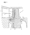
- is a partly sectional view of parts of a gas turbine with a blade according to a preferred embodiment of the invention.
- Fig. 2
- shows the blade of
fig. 1 in a side elevational view schematically. -
Fig. 1 shows in a partly sectional view parts of a stationary gas turbine. Especially, a blade 1 is shown. The blade 1 comprises a root portion. The root portion is the area under a dotted line 2 infig. 1 . The root portion has four side walls, also referred to as sides, namely twonarrow sides fig. 1 . - Furthermore, the blade 1 comprises an airfoil which is depicted in
fig. 1 above the dotted line 2. The airfoil of blade 1 is arranged in a channel for a stream of hot gas 7 - a main flow path of working fluid. The hot gas 7 is directed over the airfoil of the blade 1 to extract energy from the hot gas 7 for rotating a turbine rotor. The blade 1 is arranged on the turbine rotor (not shown). - A nozzle guide vane 9 (NGV) is arranged upstream of the airfoil of the blade 1. The
nozzle guide vane 9 provides a constant and directed stream of hot gas 7 to rotating airfoils like the airfoil of blade 1. It should be noted that during rotation of the turbine rotor airfoils of several blades pass thenozzle guide vane 9. On the other hand, in the circumferential channel for the hot gas 7, a plurality ofnozzle guide vanes 9 are arranged for directing the flow of hot gas 7. - The blade 1 is typically a unitary casting of high strength metal containing high amounts of alloying elements such as nickel. The blade 1 is suitable for withstanding the high temperature of the hot gas 7 during operation. Additionally the material forming the blade 1 is suitable for high stresses in combination with high temperatures. This is due to the fact that during rotation of the turbine rotor, the blade 1 is subject to high forces.
- Nevertheless, a cooling system should be provided for cooling at least some regions of the blade 1 during operation. For this purpose, a cooling
air supply passage 10 is arranged in the root portion of the blade 1. - The cooling
air supply passage 10 serves for guiding cooling air into a serpentine cooler 11 which is arranged inside of the airfoil of the blade 1. Typically, airfoil of the blade 1 comprises openings for directing cooling air to the surface of the airfoil of the blade 1. - The preferred embodiment shown in
fig. 1 comprises an additionalcooling air bleed 13 being arranged in the root portion and being in fluid connection with the coolingair supply passage 10. The coolingair bleed 13 comprises anozzle 14 on thenarrow side 4 of the root portion of the blade 1. - The
nozzle 14 is formed by a hole machined in the root portion. The axial direction of the hole of thenozzle 14 is directed at least partially in a longitudinal direction of the blade 1. The longitudinal direction of the blade 1 is a radial direction with respect to the rotating turbine rotor on which the blade 1 is fixed. - In
fig. 1 , the hole of thenozzle 14 is directed slightly upwards. Upwards means in direction of the main flow path or away from the axis of rotation of the gas turbine rotor. In other words, upwards means a direction from a blade root to the blade airfoil. The angle with respect to the longitudinal axis of the blade 1 is between 100° and 115°. Such an angle ensures that the cooling air jet throughnozzle 14 is accelerated by the rotation of the turbine rotor. Moreover, thebleed 13 or the axial direction of the hole of thenozzle 14 of thebleed 13, respectively, is inclined in respect to a direction of a main flow path or the stream of the hot gas 7. - The cooling air leaving the
nozzle 14 impinges directly the extreme edges ofplatform region platform regions - It should be noted that the
platform regions upper blade platform 20 of the blade 1 and alower blade platform 21 of the blade 1 form a labyrinth-sealing. The labyrinth-sealing separates the inner regions of the gas turbine from the channel filled with the hot gas 7. - The inner regions of the gas turbine are flooded with cooling air. However, in the region of the labyrinth-sealing formed by
platforms nozzle 14 has the advantage of a better cooling ofplatform regions - Particularly cooling air will be directed via the cooling
air bleed 13 towards a rim and/or atip 24 of theplatform region 18, the rim and/or thetip 24 being part of the labyrinth-sealing and directed towards the blade. Cooling air may hit the rim and/or thetip 24 and an upper surface ofplatform region 18, optionally also a lower surface ofplatform region 18. - On the downstream side of blade 1, a
further platform region 23 of a downstream nozzle guide vane is arranged. Thefurther platform region 23 can be cooled when necessary with an additional cooling air bleed. - Such an additional cooling air bleed comprises a further nozzle between the
upper blade platform 20 and thelower blade platform 21 on the downstreamnarrow side 5 of blade 1. The further nozzle provides a machined hole as well as the nozzle directed on theplatform regions - In
fig. 2 , a schematic view of blade 1 is depicted. It should be noted that same parts infig. 2 have same reference signs as infig. 1 . For the sake of clearness, these parts are not been described again. - In
fig. 2 , thenozzle 14 with its machined hole on thenarrow side 4 of the blade 1 is shown. The hole is arranged between theupper blade platform 20 and thelower blade platform 21. The broad sides of the root region of the blade 1 are formed like a dovetail to ensure a secure fixing of the blade 1 in the rotor disc of the turbine rotor (rotor disc not shown in the figures). - In typical embodiments, the nozzle is placed below the upper platform or above the lower platform. As mentioned above, other positions may provide better cooling depending on the design of the platforms. Also design and stress conditions may influence the positioning of the nozzle.
- Further typical embodiments of the invention comprise more than one hole between the upper platform region. As the blades 1 of a turbine rotor pass several nozzle guide vanes, the holes of the
nozzles 14 of the several blades 1 are moving along the extreme edges of the platform region of the nozzle guide vane (seefig. 1 ). Therefore, a continuous cooling of the platform region is ensured - even though the cooling air is distributed by holes being spaced apart. - As a further positive side effect, the sealing between the channel for the hot gas 7 and the inner region of the turbo machine is improved. Therefore, not only the extreme edges of the platform regions of the nozzle guide vane are subject to a better cooling. With the invention, the whole area including extreme edges of the platforms of the blade is provided with a better cooling reducing corrosion and wear.
- Even though the embodiments show a blade of a gas turbine as an example, the same principle of cooling can also be advantageously applied to blades of other turbo machines. Moreover, the invention is not confined to the described preferred embodiment. The scope of the invention is restricted only by the claims.
Claims (13)
- Blade (1) for a turbomachine, particularly a gas turbine, the blade (1) particularly being arrangeable on a turbine rotor of the gas turbine, the blade (1) comprising:- an airfoil and a root portion, both being integrally to said blade;- said airfoil having a cooler arranged inside of the airfoil;- said root portion having two narrow sides (4, 5) and two broad sides;- a cooling air supply passage (10) in the root portion for guiding cooling air into the cooler; and- a cooling air bleed (13) being arranged in the root portion and being in fluid connection with the cooling air supply passage (10);wherein the cooling air bleed (13) comprises a nozzle (14) on one of the narrow sides (4, 5) of the root portion, and wherein the nozzle (14) is formed by a hole,
characterized in that
the root portion comprises an upper blade platform (20) and a lower blade platform (21), with the upper blade platform (20)
and the lower blade platform (21) being embodied as parts of a labyrinth-sealing when assembled in the turbomachine and
the nozzle (14) being arranged between the upper blade platform (20) and the lower blade platform (21) with an axial direction of the hole inclined upward between 92° and 135° with respect to the longitudinal direction of the blade (1). - Blade (1) according to claim 1,
characterized in that the hole of the nozzle (14) is machined in the root portion. - Blade (1) according to one of the preceding claims,
characterized in that the nozzle (14) being arranged on a front surface of the blade (1). - Blade (1) according to one of the preceding claims, characterized in that the nozzle (14) being arranged for generating an air flow being directed towards a platform region (17, 18) of an adjacent nozzle guide vane (9) when assembled in the turbomachine.
- Blade (1) according to claim 4,
characterized in that the air flow being directed towards a rim and/or tip (24) of the platform region (18), wherein the rim and/or tip (24) being directed towards the blade (1) when assembled in the turbomachine. - Blade (1) according to claim 4 or 5,
characterized in that the rim and/or tip (24) being part of the labyrinth-sealing when assembled in the turbomachine. - Blade (1) according to one of the preceding claims,
characterized in that the cooling air bleed (13) comprises a plurality of nozzles (14) on one of the narrow sides (4, 5) of the root portion. - Turbomachine comprising- a turbine rotor with at least one blade (1) according to one of the preceding claims;- a plurality of nozzle guide vanes (9) being arranged upstream of the turbine rotor, wherein the nozzle (14) comprised in the root portion of the blade (1) being directed towards a platform region (17, 18) of the nozzle guide vanes (9).
- Turbomachine according to claim 8,
characterized in that the nozzle (14) being directed to an edge, embodied as a rim and/or tip (24), of the platform region (17, 18) of the nozzle guide vane (9). - Turbomachine according to claim 8 or 9, characterized in that the platform regions (17, 18) of the nozzle guide vane (9) together with an upper blade platform (20) and a lower blade platform (21) of the blade (1) form the labyrinth-sealing.
- Turbomachine according to claim 10, characterized in that the labyrinth-sealing separates inner regions of the gas turbine from a channel filled with a hot gas (7).
- Turbomachine according to any of the claims 8 to 11,
characterized in that the axial direction of at least one of the holes lying at least essentially in a radial plane of the turbine rotor. - Turbomachine according to any of the claims 9 to 11,
characterized in that the axial direction of at least one of the holes being inclined with respect to a radial plane of the turbine rotor, wherein the axial direction of at least one of the holes has the same direction as the direction of rotation of the blade (1).
Priority Applications (1)
| Application Number | Priority Date | Filing Date | Title |
|---|---|---|---|
| EP11745752.3A EP2580429B1 (en) | 2010-08-30 | 2011-08-08 | Blade for a turbo machine |
Applications Claiming Priority (3)
| Application Number | Priority Date | Filing Date | Title |
|---|---|---|---|
| EP10174523A EP2423435A1 (en) | 2010-08-30 | 2010-08-30 | Blade for a turbo machine |
| PCT/EP2011/063641 WO2012028424A1 (en) | 2010-08-30 | 2011-08-08 | Blade for a turbo machine |
| EP11745752.3A EP2580429B1 (en) | 2010-08-30 | 2011-08-08 | Blade for a turbo machine |
Publications (2)
| Publication Number | Publication Date |
|---|---|
| EP2580429A1 EP2580429A1 (en) | 2013-04-17 |
| EP2580429B1 true EP2580429B1 (en) | 2014-08-20 |
Family
ID=43530518
Family Applications (2)
| Application Number | Title | Priority Date | Filing Date |
|---|---|---|---|
| EP10174523A Withdrawn EP2423435A1 (en) | 2010-08-30 | 2010-08-30 | Blade for a turbo machine |
| EP11745752.3A Not-in-force EP2580429B1 (en) | 2010-08-30 | 2011-08-08 | Blade for a turbo machine |
Family Applications Before (1)
| Application Number | Title | Priority Date | Filing Date |
|---|---|---|---|
| EP10174523A Withdrawn EP2423435A1 (en) | 2010-08-30 | 2010-08-30 | Blade for a turbo machine |
Country Status (4)
| Country | Link |
|---|---|
| US (1) | US9341078B2 (en) |
| EP (2) | EP2423435A1 (en) |
| RU (1) | RU2577688C2 (en) |
| WO (1) | WO2012028424A1 (en) |
Families Citing this family (18)
| Publication number | Priority date | Publication date | Assignee | Title |
|---|---|---|---|---|
| US8979481B2 (en) * | 2011-10-26 | 2015-03-17 | General Electric Company | Turbine bucket angel wing features for forward cavity flow control and related method |
| WO2013167346A1 (en) * | 2012-05-08 | 2013-11-14 | Siemens Aktiengesellschaft | Turbine rotor blade and axial rotor blade section for a gas turbine |
| US10180067B2 (en) * | 2012-05-31 | 2019-01-15 | United Technologies Corporation | Mate face cooling holes for gas turbine engine component |
| EP2759676A1 (en) * | 2013-01-28 | 2014-07-30 | Siemens Aktiengesellschaft | Turbine arrangement with improved sealing effect at a seal |
| EP2759675A1 (en) * | 2013-01-28 | 2014-07-30 | Siemens Aktiengesellschaft | Turbine arrangement with improved sealing effect at a seal |
| JP6024985B2 (en) * | 2013-05-30 | 2016-11-16 | 株式会社オートネットワーク技術研究所 | Terminal block |
| US10364682B2 (en) * | 2013-09-17 | 2019-07-30 | United Technologies Corporation | Platform cooling core for a gas turbine engine rotor blade |
| JP6677969B2 (en) * | 2015-01-27 | 2020-04-08 | 三菱重工業株式会社 | Turbine blade, turbine, and method of manufacturing turbine blade |
| FR3034129B1 (en) | 2015-03-27 | 2019-05-17 | Safran Aircraft Engines | MOBILE TURBINE AUB WITH IMPROVED DESIGN FOR AN AIRCRAFT TURBOMACHINE |
| DE102015111843A1 (en) | 2015-07-21 | 2017-01-26 | Rolls-Royce Deutschland Ltd & Co Kg | Turbine with cooled turbine vanes |
| US20170044908A1 (en) * | 2015-08-14 | 2017-02-16 | United Technologies Corporation | Apparatus and method for cooling gas turbine engine components |
| CN105156678A (en) * | 2015-09-07 | 2015-12-16 | 发基化学品(张家港)有限公司 | Cooling equipment for reaction kettle mixer shaft packing seal |
| US10273808B2 (en) | 2015-11-11 | 2019-04-30 | United Technologies Corporation | Low loss airflow port |
| US10240461B2 (en) * | 2016-01-08 | 2019-03-26 | General Electric Company | Stator rim for a turbine engine |
| EP3232000A1 (en) | 2016-04-15 | 2017-10-18 | Siemens Aktiengesellschaft | Platform of a rotor blade with film cooling holes in the platform and corresponding turbomaschine |
| EP3342979B1 (en) * | 2016-12-30 | 2020-06-17 | Ansaldo Energia Switzerland AG | Gas turbine comprising cooled rotor disks |
| US10633992B2 (en) | 2017-03-08 | 2020-04-28 | Pratt & Whitney Canada Corp. | Rim seal |
| CN117090643B (en) * | 2023-10-20 | 2024-01-02 | 中国航发沈阳发动机研究所 | A powerful cooling turbine rotor blade air supply structure |
Family Cites Families (19)
| Publication number | Priority date | Publication date | Assignee | Title |
|---|---|---|---|---|
| GB9305012D0 (en) * | 1993-03-11 | 1993-04-28 | Rolls Royce Plc | Sealing structures for gas turbine engines |
| US5358374A (en) * | 1993-07-21 | 1994-10-25 | General Electric Company | Turbine nozzle backflow inhibitor |
| JP3192854B2 (en) * | 1993-12-28 | 2001-07-30 | 株式会社東芝 | Turbine cooling blade |
| DE69505407T2 (en) * | 1994-08-24 | 1999-05-27 | Westinghouse Electric Corp., Pittsburgh, Pa. | GAS TURBINE BLADE WITH COOLED PLATFORM |
| WO1996015357A1 (en) * | 1994-11-10 | 1996-05-23 | Westinghouse Electric Corporation | Gas turbine vane with a cooled inner shroud |
| JP3758792B2 (en) * | 1997-02-25 | 2006-03-22 | 三菱重工業株式会社 | Gas turbine rotor platform cooling mechanism |
| EP0902164B1 (en) * | 1997-09-15 | 2003-04-02 | ALSTOM (Switzerland) Ltd | Cooling of the shroud in a gas turbine |
| US6341939B1 (en) | 2000-07-31 | 2002-01-29 | General Electric Company | Tandem cooling turbine blade |
| RU2183747C1 (en) | 2000-10-05 | 2002-06-20 | Акционерное общество открытого типа "Ленинградский Металлический завод" | Gas turbine wheel cooling device |
| US6402471B1 (en) * | 2000-11-03 | 2002-06-11 | General Electric Company | Turbine blade for gas turbine engine and method of cooling same |
| US6779972B2 (en) | 2002-10-31 | 2004-08-24 | General Electric Company | Flowpath sealing and streamlining configuration for a turbine |
| GB0405679D0 (en) * | 2004-03-13 | 2004-04-21 | Rolls Royce Plc | A mounting arrangement for turbine blades |
| US7467922B2 (en) * | 2005-07-25 | 2008-12-23 | Siemens Aktiengesellschaft | Cooled turbine blade or vane for a gas turbine, and use of a turbine blade or vane of this type |
| US7244101B2 (en) * | 2005-10-04 | 2007-07-17 | General Electric Company | Dust resistant platform blade |
| US7819629B2 (en) * | 2007-02-15 | 2010-10-26 | Siemens Energy, Inc. | Blade for a gas turbine |
| JP5281245B2 (en) * | 2007-02-21 | 2013-09-04 | 三菱重工業株式会社 | Gas turbine rotor platform cooling structure |
| US8262342B2 (en) * | 2008-07-10 | 2012-09-11 | Honeywell International Inc. | Gas turbine engine assemblies with recirculated hot gas ingestion |
| US8277177B2 (en) * | 2009-01-19 | 2012-10-02 | Siemens Energy, Inc. | Fluidic rim seal system for turbine engines |
| US8529194B2 (en) * | 2010-05-19 | 2013-09-10 | General Electric Company | Shank cavity and cooling hole |
-
2010
- 2010-08-30 EP EP10174523A patent/EP2423435A1/en not_active Withdrawn
-
2011
- 2011-08-08 EP EP11745752.3A patent/EP2580429B1/en not_active Not-in-force
- 2011-08-08 RU RU2013113946/06A patent/RU2577688C2/en not_active IP Right Cessation
- 2011-08-08 US US13/818,121 patent/US9341078B2/en not_active Expired - Fee Related
- 2011-08-08 WO PCT/EP2011/063641 patent/WO2012028424A1/en not_active Ceased
Also Published As
| Publication number | Publication date |
|---|---|
| US9341078B2 (en) | 2016-05-17 |
| RU2577688C2 (en) | 2016-03-20 |
| RU2013113946A (en) | 2014-10-10 |
| EP2423435A1 (en) | 2012-02-29 |
| WO2012028424A1 (en) | 2012-03-08 |
| EP2580429A1 (en) | 2013-04-17 |
| US20130156598A1 (en) | 2013-06-20 |
Similar Documents
| Publication | Publication Date | Title |
|---|---|---|
| US9341078B2 (en) | Blade for a turbo machine having labyrinth seal cooling passage | |
| US9127560B2 (en) | Cooled turbine blade and method for cooling a turbine blade | |
| CN107035422B (en) | Turbine rotor blade with midspan shroud | |
| JP5503140B2 (en) | Divergent turbine nozzle | |
| EP3144479A1 (en) | Stator component cooling | |
| US9869185B2 (en) | Rotating turbine component with preferential hole alignment | |
| CN107084004B (en) | Impact holes for turbine engine components | |
| CA3065116C (en) | Turbine assembly for impingement cooling and method of assembling | |
| JP2017198202A (en) | System for cooling rail of turbine blade tip shroud | |
| EP2597260B1 (en) | Bucket assembly for turbine system | |
| US8235652B2 (en) | Turbine nozzle segment | |
| JP6405102B2 (en) | Turbine airfoil assembly | |
| EP2574728A1 (en) | Clearance flow control assembly having rail member and corresponding turbine | |
| EP2672062A2 (en) | Nozzle diaphragm inducer | |
| US20170152752A1 (en) | Turbomachine blade with generally radial cooling conduit to wheel space | |
| JP2005351277A (en) | Method and apparatus for cooling gas turbine rotor blades | |
| CN204312137U (en) | Turbogenerator and turbomachine injection nozzle wheel blade section | |
| JP2017145826A (en) | Gas turbine engine trailing edge discharge hole | |
| US11391161B2 (en) | Component for a turbine engine with a cooling hole | |
| EP1749967B1 (en) | Cooling arrangement of a blade shroud and corresponding gas turbine | |
| EP2713009B1 (en) | Cooling method and system for cooling blades of at least one blade row in a rotary flow machine | |
| GB2467350A (en) | Cooling and sealing in gas turbine engine turbine stage | |
| EP3241991A1 (en) | Turbine assembly | |
| US20250163813A1 (en) | Airfoil assembly with platform cooling | |
| EP2378071A1 (en) | Turbine assembly having cooling arrangement and method of cooling |
Legal Events
| Date | Code | Title | Description |
|---|---|---|---|
| PUAI | Public reference made under article 153(3) epc to a published international application that has entered the european phase |
Free format text: ORIGINAL CODE: 0009012 |
|
| 17P | Request for examination filed |
Effective date: 20130109 |
|
| AK | Designated contracting states |
Kind code of ref document: A1 Designated state(s): AL AT BE BG CH CY CZ DE DK EE ES FI FR GB GR HR HU IE IS IT LI LT LU LV MC MK MT NL NO PL PT RO RS SE SI SK SM TR |
|
| DAX | Request for extension of the european patent (deleted) | ||
| REG | Reference to a national code |
Ref country code: DE Ref legal event code: R079 Ref document number: 602011009315 Country of ref document: DE Free format text: PREVIOUS MAIN CLASS: F01D0005080000 Ipc: F01D0025120000 |
|
| GRAP | Despatch of communication of intention to grant a patent |
Free format text: ORIGINAL CODE: EPIDOSNIGR1 |
|
| RIC1 | Information provided on ipc code assigned before grant |
Ipc: F01D 25/12 20060101AFI20140207BHEP Ipc: F01D 5/08 20060101ALI20140207BHEP Ipc: F01D 5/18 20060101ALI20140207BHEP |
|
| INTG | Intention to grant announced |
Effective date: 20140304 |
|
| GRAS | Grant fee paid |
Free format text: ORIGINAL CODE: EPIDOSNIGR3 |
|
| GRAA | (expected) grant |
Free format text: ORIGINAL CODE: 0009210 |
|
| AK | Designated contracting states |
Kind code of ref document: B1 Designated state(s): AL AT BE BG CH CY CZ DE DK EE ES FI FR GB GR HR HU IE IS IT LI LT LU LV MC MK MT NL NO PL PT RO RS SE SI SK SM TR |
|
| REG | Reference to a national code |
Ref country code: GB Ref legal event code: FG4D |
|
| REG | Reference to a national code |
Ref country code: CH Ref legal event code: EP |
|
| REG | Reference to a national code |
Ref country code: AT Ref legal event code: REF Ref document number: 683594 Country of ref document: AT Kind code of ref document: T Effective date: 20140915 |
|
| REG | Reference to a national code |
Ref country code: IE Ref legal event code: FG4D |
|
| REG | Reference to a national code |
Ref country code: DE Ref legal event code: R096 Ref document number: 602011009315 Country of ref document: DE Effective date: 20141002 |
|
| REG | Reference to a national code |
Ref country code: AT Ref legal event code: MK05 Ref document number: 683594 Country of ref document: AT Kind code of ref document: T Effective date: 20140820 |
|
| REG | Reference to a national code |
Ref country code: NL Ref legal event code: VDEP Effective date: 20140820 |
|
| REG | Reference to a national code |
Ref country code: LT Ref legal event code: MG4D |
|
| PG25 | Lapsed in a contracting state [announced via postgrant information from national office to epo] |
Ref country code: PT Free format text: LAPSE BECAUSE OF FAILURE TO SUBMIT A TRANSLATION OF THE DESCRIPTION OR TO PAY THE FEE WITHIN THE PRESCRIBED TIME-LIMIT Effective date: 20141222 Ref country code: LT Free format text: LAPSE BECAUSE OF FAILURE TO SUBMIT A TRANSLATION OF THE DESCRIPTION OR TO PAY THE FEE WITHIN THE PRESCRIBED TIME-LIMIT Effective date: 20140820 Ref country code: ES Free format text: LAPSE BECAUSE OF FAILURE TO SUBMIT A TRANSLATION OF THE DESCRIPTION OR TO PAY THE FEE WITHIN THE PRESCRIBED TIME-LIMIT Effective date: 20140820 Ref country code: SE Free format text: LAPSE BECAUSE OF FAILURE TO SUBMIT A TRANSLATION OF THE DESCRIPTION OR TO PAY THE FEE WITHIN THE PRESCRIBED TIME-LIMIT Effective date: 20140820 Ref country code: BG Free format text: LAPSE BECAUSE OF FAILURE TO SUBMIT A TRANSLATION OF THE DESCRIPTION OR TO PAY THE FEE WITHIN THE PRESCRIBED TIME-LIMIT Effective date: 20141120 Ref country code: GR Free format text: LAPSE BECAUSE OF FAILURE TO SUBMIT A TRANSLATION OF THE DESCRIPTION OR TO PAY THE FEE WITHIN THE PRESCRIBED TIME-LIMIT Effective date: 20141121 Ref country code: FI Free format text: LAPSE BECAUSE OF FAILURE TO SUBMIT A TRANSLATION OF THE DESCRIPTION OR TO PAY THE FEE WITHIN THE PRESCRIBED TIME-LIMIT Effective date: 20140820 Ref country code: NO Free format text: LAPSE BECAUSE OF FAILURE TO SUBMIT A TRANSLATION OF THE DESCRIPTION OR TO PAY THE FEE WITHIN THE PRESCRIBED TIME-LIMIT Effective date: 20141120 |
|
| PG25 | Lapsed in a contracting state [announced via postgrant information from national office to epo] |
Ref country code: IS Free format text: LAPSE BECAUSE OF FAILURE TO SUBMIT A TRANSLATION OF THE DESCRIPTION OR TO PAY THE FEE WITHIN THE PRESCRIBED TIME-LIMIT Effective date: 20141220 Ref country code: LV Free format text: LAPSE BECAUSE OF FAILURE TO SUBMIT A TRANSLATION OF THE DESCRIPTION OR TO PAY THE FEE WITHIN THE PRESCRIBED TIME-LIMIT Effective date: 20140820 Ref country code: AT Free format text: LAPSE BECAUSE OF FAILURE TO SUBMIT A TRANSLATION OF THE DESCRIPTION OR TO PAY THE FEE WITHIN THE PRESCRIBED TIME-LIMIT Effective date: 20140820 Ref country code: RS Free format text: LAPSE BECAUSE OF FAILURE TO SUBMIT A TRANSLATION OF THE DESCRIPTION OR TO PAY THE FEE WITHIN THE PRESCRIBED TIME-LIMIT Effective date: 20140820 Ref country code: HR Free format text: LAPSE BECAUSE OF FAILURE TO SUBMIT A TRANSLATION OF THE DESCRIPTION OR TO PAY THE FEE WITHIN THE PRESCRIBED TIME-LIMIT Effective date: 20140820 |
|
| PG25 | Lapsed in a contracting state [announced via postgrant information from national office to epo] |
Ref country code: NL Free format text: LAPSE BECAUSE OF FAILURE TO SUBMIT A TRANSLATION OF THE DESCRIPTION OR TO PAY THE FEE WITHIN THE PRESCRIBED TIME-LIMIT Effective date: 20140820 |
|
| PG25 | Lapsed in a contracting state [announced via postgrant information from national office to epo] |
Ref country code: RO Free format text: LAPSE BECAUSE OF FAILURE TO SUBMIT A TRANSLATION OF THE DESCRIPTION OR TO PAY THE FEE WITHIN THE PRESCRIBED TIME-LIMIT Effective date: 20140820 Ref country code: DK Free format text: LAPSE BECAUSE OF FAILURE TO SUBMIT A TRANSLATION OF THE DESCRIPTION OR TO PAY THE FEE WITHIN THE PRESCRIBED TIME-LIMIT Effective date: 20140820 Ref country code: SK Free format text: LAPSE BECAUSE OF FAILURE TO SUBMIT A TRANSLATION OF THE DESCRIPTION OR TO PAY THE FEE WITHIN THE PRESCRIBED TIME-LIMIT Effective date: 20140820 Ref country code: CZ Free format text: LAPSE BECAUSE OF FAILURE TO SUBMIT A TRANSLATION OF THE DESCRIPTION OR TO PAY THE FEE WITHIN THE PRESCRIBED TIME-LIMIT Effective date: 20140820 Ref country code: EE Free format text: LAPSE BECAUSE OF FAILURE TO SUBMIT A TRANSLATION OF THE DESCRIPTION OR TO PAY THE FEE WITHIN THE PRESCRIBED TIME-LIMIT Effective date: 20140820 Ref country code: IT Free format text: LAPSE BECAUSE OF FAILURE TO SUBMIT A TRANSLATION OF THE DESCRIPTION OR TO PAY THE FEE WITHIN THE PRESCRIBED TIME-LIMIT Effective date: 20140820 |
|
| REG | Reference to a national code |
Ref country code: DE Ref legal event code: R097 Ref document number: 602011009315 Country of ref document: DE |
|
| PG25 | Lapsed in a contracting state [announced via postgrant information from national office to epo] |
Ref country code: PL Free format text: LAPSE BECAUSE OF FAILURE TO SUBMIT A TRANSLATION OF THE DESCRIPTION OR TO PAY THE FEE WITHIN THE PRESCRIBED TIME-LIMIT Effective date: 20140820 |
|
| PLBE | No opposition filed within time limit |
Free format text: ORIGINAL CODE: 0009261 |
|
| STAA | Information on the status of an ep patent application or granted ep patent |
Free format text: STATUS: NO OPPOSITION FILED WITHIN TIME LIMIT |
|
| 26N | No opposition filed |
Effective date: 20150521 |
|
| PG25 | Lapsed in a contracting state [announced via postgrant information from national office to epo] |
Ref country code: SI Free format text: LAPSE BECAUSE OF FAILURE TO SUBMIT A TRANSLATION OF THE DESCRIPTION OR TO PAY THE FEE WITHIN THE PRESCRIBED TIME-LIMIT Effective date: 20140820 |
|
| PG25 | Lapsed in a contracting state [announced via postgrant information from national office to epo] |
Ref country code: MC Free format text: LAPSE BECAUSE OF FAILURE TO SUBMIT A TRANSLATION OF THE DESCRIPTION OR TO PAY THE FEE WITHIN THE PRESCRIBED TIME-LIMIT Effective date: 20140820 Ref country code: LU Free format text: LAPSE BECAUSE OF FAILURE TO SUBMIT A TRANSLATION OF THE DESCRIPTION OR TO PAY THE FEE WITHIN THE PRESCRIBED TIME-LIMIT Effective date: 20150808 |
|
| REG | Reference to a national code |
Ref country code: CH Ref legal event code: PL |
|
| PG25 | Lapsed in a contracting state [announced via postgrant information from national office to epo] |
Ref country code: CH Free format text: LAPSE BECAUSE OF NON-PAYMENT OF DUE FEES Effective date: 20150831 Ref country code: LI Free format text: LAPSE BECAUSE OF NON-PAYMENT OF DUE FEES Effective date: 20150831 |
|
| REG | Reference to a national code |
Ref country code: IE Ref legal event code: MM4A |
|
| PG25 | Lapsed in a contracting state [announced via postgrant information from national office to epo] |
Ref country code: BE Free format text: LAPSE BECAUSE OF FAILURE TO SUBMIT A TRANSLATION OF THE DESCRIPTION OR TO PAY THE FEE WITHIN THE PRESCRIBED TIME-LIMIT Effective date: 20140820 Ref country code: IE Free format text: LAPSE BECAUSE OF NON-PAYMENT OF DUE FEES Effective date: 20150808 |
|
| REG | Reference to a national code |
Ref country code: FR Ref legal event code: PLFP Year of fee payment: 6 |
|
| PG25 | Lapsed in a contracting state [announced via postgrant information from national office to epo] |
Ref country code: MT Free format text: LAPSE BECAUSE OF FAILURE TO SUBMIT A TRANSLATION OF THE DESCRIPTION OR TO PAY THE FEE WITHIN THE PRESCRIBED TIME-LIMIT Effective date: 20140820 |
|
| PG25 | Lapsed in a contracting state [announced via postgrant information from national office to epo] |
Ref country code: HU Free format text: LAPSE BECAUSE OF FAILURE TO SUBMIT A TRANSLATION OF THE DESCRIPTION OR TO PAY THE FEE WITHIN THE PRESCRIBED TIME-LIMIT; INVALID AB INITIO Effective date: 20110808 |
|
| PG25 | Lapsed in a contracting state [announced via postgrant information from national office to epo] |
Ref country code: CY Free format text: LAPSE BECAUSE OF FAILURE TO SUBMIT A TRANSLATION OF THE DESCRIPTION OR TO PAY THE FEE WITHIN THE PRESCRIBED TIME-LIMIT Effective date: 20140820 |
|
| PG25 | Lapsed in a contracting state [announced via postgrant information from national office to epo] |
Ref country code: SM Free format text: LAPSE BECAUSE OF FAILURE TO SUBMIT A TRANSLATION OF THE DESCRIPTION OR TO PAY THE FEE WITHIN THE PRESCRIBED TIME-LIMIT Effective date: 20140820 |
|
| REG | Reference to a national code |
Ref country code: FR Ref legal event code: PLFP Year of fee payment: 7 |
|
| PG25 | Lapsed in a contracting state [announced via postgrant information from national office to epo] |
Ref country code: TR Free format text: LAPSE BECAUSE OF FAILURE TO SUBMIT A TRANSLATION OF THE DESCRIPTION OR TO PAY THE FEE WITHIN THE PRESCRIBED TIME-LIMIT Effective date: 20140820 |
|
| PG25 | Lapsed in a contracting state [announced via postgrant information from national office to epo] |
Ref country code: MK Free format text: LAPSE BECAUSE OF FAILURE TO SUBMIT A TRANSLATION OF THE DESCRIPTION OR TO PAY THE FEE WITHIN THE PRESCRIBED TIME-LIMIT Effective date: 20140820 |
|
| REG | Reference to a national code |
Ref country code: FR Ref legal event code: PLFP Year of fee payment: 8 |
|
| PG25 | Lapsed in a contracting state [announced via postgrant information from national office to epo] |
Ref country code: AL Free format text: LAPSE BECAUSE OF FAILURE TO SUBMIT A TRANSLATION OF THE DESCRIPTION OR TO PAY THE FEE WITHIN THE PRESCRIBED TIME-LIMIT Effective date: 20140820 |
|
| PGFP | Annual fee paid to national office [announced via postgrant information from national office to epo] |
Ref country code: FR Payment date: 20180822 Year of fee payment: 8 |
|
| PGFP | Annual fee paid to national office [announced via postgrant information from national office to epo] |
Ref country code: GB Payment date: 20180809 Year of fee payment: 8 |
|
| PGFP | Annual fee paid to national office [announced via postgrant information from national office to epo] |
Ref country code: DE Payment date: 20181019 Year of fee payment: 8 |
|
| REG | Reference to a national code |
Ref country code: DE Ref legal event code: R119 Ref document number: 602011009315 Country of ref document: DE |
|
| GBPC | Gb: european patent ceased through non-payment of renewal fee |
Effective date: 20190808 |
|
| PG25 | Lapsed in a contracting state [announced via postgrant information from national office to epo] |
Ref country code: FR Free format text: LAPSE BECAUSE OF NON-PAYMENT OF DUE FEES Effective date: 20190831 Ref country code: DE Free format text: LAPSE BECAUSE OF NON-PAYMENT OF DUE FEES Effective date: 20200303 |
|
| PG25 | Lapsed in a contracting state [announced via postgrant information from national office to epo] |
Ref country code: GB Free format text: LAPSE BECAUSE OF NON-PAYMENT OF DUE FEES Effective date: 20190808 |