EP2579543A1 - IP address assigning method and data centre using such method - Google Patents
IP address assigning method and data centre using such method Download PDFInfo
- Publication number
- EP2579543A1 EP2579543A1 EP20120158635 EP12158635A EP2579543A1 EP 2579543 A1 EP2579543 A1 EP 2579543A1 EP 20120158635 EP20120158635 EP 20120158635 EP 12158635 A EP12158635 A EP 12158635A EP 2579543 A1 EP2579543 A1 EP 2579543A1
- Authority
- EP
- European Patent Office
- Prior art keywords
- address
- network
- network device
- assigning
- installation position
- Prior art date
- Legal status (The legal status is an assumption and is not a legal conclusion. Google has not performed a legal analysis and makes no representation as to the accuracy of the status listed.)
- Withdrawn
Links
Images



Classifications
-
- H—ELECTRICITY
- H04—ELECTRIC COMMUNICATION TECHNIQUE
- H04L—TRANSMISSION OF DIGITAL INFORMATION, e.g. TELEGRAPHIC COMMUNICATION
- H04L61/00—Network arrangements, protocols or services for addressing or naming
- H04L61/50—Address allocation
- H04L61/5007—Internet protocol [IP] addresses
- H04L61/5014—Internet protocol [IP] addresses using dynamic host configuration protocol [DHCP] or bootstrap protocol [BOOTP]
-
- H—ELECTRICITY
- H04—ELECTRIC COMMUNICATION TECHNIQUE
- H04L—TRANSMISSION OF DIGITAL INFORMATION, e.g. TELEGRAPHIC COMMUNICATION
- H04L61/00—Network arrangements, protocols or services for addressing or naming
- H04L61/09—Mapping addresses
- H04L61/10—Mapping addresses of different types
-
- H—ELECTRICITY
- H04—ELECTRIC COMMUNICATION TECHNIQUE
- H04L—TRANSMISSION OF DIGITAL INFORMATION, e.g. TELEGRAPHIC COMMUNICATION
- H04L2101/00—Indexing scheme associated with group H04L61/00
- H04L2101/60—Types of network addresses
- H04L2101/69—Types of network addresses using geographic information, e.g. room number
-
- H—ELECTRICITY
- H04—ELECTRIC COMMUNICATION TECHNIQUE
- H04L—TRANSMISSION OF DIGITAL INFORMATION, e.g. TELEGRAPHIC COMMUNICATION
- H04L41/00—Arrangements for maintenance, administration or management of data switching networks, e.g. of packet switching networks
- H04L41/02—Standardisation; Integration
- H04L41/0213—Standardised network management protocols, e.g. simple network management protocol [SNMP]
Definitions
- the present invention relates to an IP address assigning method, and more particularly to a method for automatically assigning IP addresses in a positioning manner and a data center using such method.
- a data center is a facility used to house a plurality of computers and/or servers.
- the computers and/or servers should be timely increased, removed or replaced. Consequently, the installation positions of the computers and/or servers in the data center can be effectively and timely adjusted in order to meet the requirements of the increasingly competitive environment.
- the computers and/or servers of the data center are in communication with each other through the network to exchange data.
- an IP address Internet Protocol address
- the data center has a DHCP (dynamic host configuration protocol) server for automatically assigning IP addresses to respective computers and/or servers.
- DHCP dynamic host configuration protocol
- the assigning method of the DHCP server is performed by referring to the usage statuses of the IP addresses and the available IP addresses (i.e. remaining IP addresses).
- the available IP addresses i.e. remaining IP addresses.
- a management program of the data center may issue a notification message to inform the maintenance worker to repair the damaged computer or server. Since the maintenance worker fails to realize the real installation position of the damaged server of the data center according to the IP address of the damaged server. That is, the damaged server needs to be searched from a great number of servers (e.g. thousands or tens of thousands of servers) of the data center by a skillful maintenance worker. The process of searching the damaged server is time-consuming and labor-intensive.
- the present invention provides an IP address assigning method and a data center using such method.
- the IP address assigning method is capable of dynamically and automatically assigning IP addresses according to the installation positions of the network devices.
- one of the network devices fails to be normally operated, it is not necessary to search the damaged network device from a great number of network devices of the data center by a skillful maintenance worker.
- the management program and the maintenance worker can quickly realize or recognize the installation position of the damaged network device. Consequently, the positioning function is achieved.
- the labor cost and the technical threshold of the maintenance worker will be largely reduced.
- an IP address assigning method includes the following steps. Firstly, an IP address request packet containing a media access control address is issued from a network device, and the IP address request packet is transmitted to a dynamic host configuration protocol (DHCP) server through a network switch. The IP address request packet is analyzed by the DHCP server, so that the media access control address is acquired. Then, at least one address forwarding table of at least one network switch is acquired by the DHCP server. Then, the at least one address forwarding table is analyzed by the DHCP server according to the media access control address, so that an assigned number of a port of the network switch which is electrically connected with the network device is acquired.
- DHCP dynamic host configuration protocol
- an available IP address is assigned to the network device by the DHCP server, or a predetermined IP address listed in an IP address assigning table is assigned to the network device according to the assigned number of the port of the network switch which is electrically connected with the network device.
- the media access control address and/or the assigned IP address is recorded in a field of the IP address assigning table corresponding to the assigned number of the port of the network switch by the DHCP server.
- An installation position of the network device is recognized according to the IP address through a network device installation position table and the IP address assigning table.
- a data center comprising a plurality of network switches, a plurality of network devices, a dynamic host configuration protocol (DHCP) server and a plurality of racks.
- DHCP dynamic host configuration protocol
- Each of the racks is installed with at least one network switch and at least one network device.
- the network switches, the network devices, the DHCP server and the racks are electrically connected with each other through a plurality of data transmission lines to define a local area network.
- the DHCP server and the network switches are in communication with each other and configured to perform an IP address assigning process comprising: (a) receiving and analyzing an IP address request packet containing a media access control address from one of the network devices requested IP address assign, so that the media access control address is acquired; (b) acquiring at least one address forwarding table of the network switch; (c) analyzing the address forwarding table according to the media access control address, thereby acquiring an assigned number of a port of the network switch which is electrically connected with the network device; (d) assigning an available IP address to the network device, or assigning a predetermined IP address listed in an IP address assigning table to the network device according to the assigned number of the port of the network switch which is electrically connected with the network device; and (e) recording the media access control address and/or the assigned IP address in a field of the IP address assigning table corresponding to the assigned number of the port of the network switch.
- An installation position of the network device is recognized according to the IP address through a network device installation position table and the
- FIG. 1 schematically illustrates the architecture of a data center according to an embodiment of the present invention
- FIG. 2 schematically illustrates the architecture of a data center using an IP address assigning method according to an embodiment of the present invention
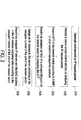
- FIG. 3 is a flowchart illustrating an IP address assigning method according to an embodiment of the present invention.
- FIG. 4 schematically illustrates the data center using an IP address assigning method and the flow path of the IP address assigning method according to an embodiment of the present invention.
- FIG. 1 schematically illustrates the architecture of a data center according to an embodiment of the present invention.
- the data center 1 has multilayered building spaces (e.g. two-layered building spaces).
- a plurality of racks A11 ⁇ A54 are located within the second layer of the building space
- a plurality of racks B11 ⁇ B54 are located within the first layer of the building space.
- the racks in each layer of the building spaces are arranged or located in an array.
- the installation positions are denoted by the numerals A11 ⁇ A54 and B11 ⁇ B54.
- the network switches within respective racks are in communication with each other through a plurality of data transmission lines 12 (e.g. Ethernet lines or fiber-optic cables).
- the network devices within the racks A11 ⁇ A54 and B11 ⁇ B54 are in communication with each other to exchange digital data and provide various Internet services (e.g. Web server or FTP server).
- FIG. 2 schematically illustrates the architecture of a data center using an IP address assigning method according to an embodiment of the present invention.
- the data center 2 includes a plurality of network switches W11 ⁇ W13, a plurality of servers (e.g. network devices or IT equipments) 1101 ⁇ 1306, a DHCP server 21, and a plurality of racks A11, A12, B13.
- the servers 1101 ⁇ 1106, 1201 ⁇ 1206 and 1301 ⁇ 1306 are disposed within the racks A11, A12 and B13, respectively.
- Each of these racks contains at least one network switch.
- the network switches W11, W12 and W13 are disposed within first receiving spaces A110, A120, B130 of the racks A11, A12, B13, respectively.
- each of the racks A11, A12 and B13 contains six servers, but it is not limited thereto.
- the network devices are illustrated by referring to the servers. Nevertheless, the network devices may be network switches other than the network switches W11 ⁇ W13.
- the DHCP server 21 is in communication with the network switches W11, W12 and W13 through data transmission lines (e.g. Ethernet lines or fiber-optic cables), thereby collectively defining a first local area network 22.
- data transmission lines e.g. Ethernet lines or fiber-optic cables
- IP addresses are assigned to corresponding servers by the DHCP server 21. Consequently, these servers 1101 ⁇ 1306 within the racks A11, A12, B13 are in communication with each other to exchange digital data and provide various Internet services (e.g. Web server or FTP server).
- Each of the network switches W11, W12 and W13 within the racks A11, A12 and B13 comprises a plurality of ports. The relationship between the ports of the network switches W11, W12 and W13 and respective servers (network devices or IT equipments) are determined according to an IP address assigning table recorded in the DHCP server 21.
- the servers 1101 ⁇ 1106 are respectively accommodated within the receiving spaces A111 ⁇ A116 of the first rack A11.
- the ports W111 ⁇ W116 of the first network switch W11 are electrically connected with the servers 1101 ⁇ 1106 of the first rack A11, sequentially and respectively.
- the servers 1201 ⁇ 1206 are respectively accommodated within the receiving spaces A121 ⁇ A126 of the second rack A12.
- the ports W121 ⁇ W126 of the second network switch W12 are electrically connected with the servers 1201 ⁇ 1206 of the second rack A12, sequentially and respectively.
- the servers 1301 ⁇ 1306 are respectively accommodated within the receiving spaces B131 ⁇ A136 of the second rack B13.
- the ports W131 ⁇ W136 of the third network switch W13 are electrically connected with the servers 1301 ⁇ 1306 of the second rack B13, sequentially and respectively.
- the data center 2 further comprises a firewall 23 and a router 24.
- the firewall 23 and the router 24 are located between the first local area network 22 and the Internet 25.
- the data packets transmitted between the first local area network 22 and the Internet 25 are managed by the firewall 23. Since the data packets transmitted between the first local area network 22 and the Internet 25 are analyzed, filtered and managed by the firewall 23, the management and safety of the network system (i.e. the first local area network 22) of the data center 2 are enhanced.
- the router 24 is used for performing an IP forwarding process to determine the path of transmitting the packet data between the first local area network 22 and the Internet 25. During operations, the router 24 determines the best path to send a data packet to its intended destination according to a route table recorded in the router 24. That is, the IP forwarding process allows the router 24 to select the best path to send the data packet.
- Table 1 is a network device installation position table showing the positions of the network devices (servers) included in the data center according to the embodiment of the present invention.
- Table 2 is an exemplary IP address assigning table.
- the network device installation position table (Table 1) and the IP address assigning table (Table 2) are stored in the DHCP server 21.
- the network device installation position table records the relationships between the ports of the network switches and the installation position of the corresponding network devices (servers).
- the IP address assigning table records the relationships between the IP addresses and the media access control (MAC) addresses of the ports of the network switches and the corresponding network devices (servers).
- MAC media access control
- the network switches W11 ⁇ W13 and the servers (network devices) 1101 ⁇ 1306 are installed at the installation positions by referring to the network device installation position table (Table 1) and then these devices are electrically connected with each other.
- Table 1 network device installation position table Network switch W11 W11(@A110) Network switch W12 W12(@A120) Network switch W13 W13(@B130) Port Location Port Location Port Location 1 A111 1 A121 1 B131 2 A112 2 A122 2 B132 3 A113 3 A123 3 B133 4 A114 4 A124 4 B134 5 A115 5 A125 5 B135 6 A116 6 A126 6 B136
- Table 2 IP address assigning table Network switch W11 W11(@A110) Network switch W12 W12(@A120) Network switch W13 W13(@B130) Port IP MAC Port IP MAC Port IP MAC 1 192.168.0 .1 Not logged in 1 192.168.0.11 Not logged in 1 192.168.0. 21 Not logged in 2 192.168.0 .2 Not logged in 2 192.168.0.12 Not logged in 2 192.168.0. 22 Not logged in 3 192.168.0 .3 Not logged in 3 192.168.0.13 Not logged in 3 192.168.0.
- the server 1101 is disposed within the second receiving space A111 of the rack A11, which is located at the first-row and first-column installation position within the second-layer building space of the data center 2.
- the server 1101 is electrically connected with the first port W111 of the first network switch W11 within the first rack A11.
- the server 1305 is disposed within the sixth receiving space B 135 of the rack B 13, which is located at the first-row and third-column installation position within the first-layer building space of the data center 2.
- the server 1305 is electrically connected with the fifth port W135 of the third network switch W 13 within the third rack B 13.
- IP address assigning method will be illustrated with reference to the flowchart of FIG. 3 as well as FIGS. 1 and 2 and Tables 1 and 2.
- the IP addresses of the servers 1101 ⁇ 1306 should be acquired.
- IP address request packets containing media access control (MAC) addresses are generated by the servers 1101 ⁇ 1306.
- the IP address request packets are transmitted form the servers 1101 ⁇ 1306 to the DHCP server 21 through corresponding ports W111 ⁇ W136 of the network switches W11 ⁇ W13 in order to request the DHCP server 21 to assign IP addresses.
- the IP address request packets are analyzed by the DHCP server 21, so that the media access control (MAC) addresses generated by the servers 1101 ⁇ 1306 are realized.
- the address forwarding tables (AFT) of the network switches W11 ⁇ W13 are acquired by the DHCP server 21 according to a simple network management protocol (SNMP) or other network management protocol.
- SNMP simple network management protocol
- the address forwarding table (AFT) records the media access control (MAC) addresses contained in the data packets which are inputted into or outputted from all ports of each network switch.
- the address forwarding tables (AFT) of the network switches W11 ⁇ W13 are analyzed by the DHCP server 21 according to the media access control (MAC) addresses contained in the IP address request packets. Consequently, the assigned numbers of the ports of the network switches that are electrically connected with the servers 1101 ⁇ 1306 (i.e. the servers issuing the IP address request packets) are acquired.
- the DHCP server 21 assigns IP addresses to the servers 1101 ⁇ 1306 that issue the IP assignment requests.
- IP addresses are successively assigned to the servers 1101 ⁇ 1306 that issue the IP assignment requests.
- predetermined IP addresses listed in the IP address assigning table are assigned to the servers 1101 ⁇ 1306 that issue the IP assignment requests according to the assigned numbers of the ports of the network switches.
- the DHCP server 21 After the IP addresses are assigned, the DHCP server 21 will record the assigned IP addresses and/or the MAC addresses of the servers 1101 ⁇ 1306 in the fields of the IP address assigning table (i.e. Table 2) corresponding to the assigned numbers of the ports of the network switches (Step S36).
- the IP address assigning table i.e. Table 2
- FIG. 4 schematically illustrates the data center using an IP address assigning method and the flow path of the IP address assigning method according to an embodiment of the present invention.
- an implementation example of the IP address assigning method will be illustrated with reference to FIGS. 1 ⁇ 4 and Tables 1 ⁇ 2.
- the IP address of the server 1306 needs to be acquired.
- an IP address request packet P1 containing a first media access control address MAC1 is generated by the server 1306.
- the IP address request packet P1 is transmitted to the DHCP server 21 through the sixth port W136 of the third network switch W13 in order to request the DHCP server 21 to assign the IP address.
- the IP address request packet P1 is analyzed by the DHCP server 21, so that the first media access control address MAC1 of the server 1306 is realized.
- the address forwarding table AFT3 of the third network switch W 13 is acquired by the DHCP server 21 according to a simple network management protocol (SNMP).
- the IP address request packet P1 is transmitted to the DHCP server 21 through the sixth port W136 of the network switch W13. Consequently, the address forwarding table AFT3 of the third network switch W13 records the information about the transmission of the IP address request packet P1 including the first media access control address MAC1 through the sixth port W136 of the third network switch W13.
- the address forwarding table AFT3 of the third network switch W13 is analyzed by the DHCP server 21 according to the first media access control address MAC1, so that the assigned number of the sixth port W136 of the third network switch W13 is acquired. That is, the DHCP server 21 can recognize that the server 1306 is electrically connected with the sixth port W136 of the third network switch W13.
- the DHCP server 21 assigns an IP address to the server 1306 according to the assigned numbers of the port of the network switch.
- an available IP address (192.168.0.26) is assigned to the server 1306 by the DHCP server 21.
- a predetermined IP address (192.168.0.26) listed in the IP address assigning table is assigned to the server 1306 according to the assigned number of the sixth port W136 of the third network switch W 13.
- the DHCP server 21 will record the assigned IP address (192.168.0.26) and/or the first media access control address MAC1 (e.g. 00-16-EC-E9-FF-A7) of the server 1306 in the fields of the IP address assigning table (i.e. Table 2) corresponding to the sixth port W136 of the third network switch W13 (Step S36).
- the IP address assigning table i.e. Table 2
- Table 3 is another exemplary IP address assigning table. Please refer to Tables 1, 2 and 3. After the IP addresses of all servers 1101 ⁇ 1306 are acquired by the above procedure, the assigned IP addresses (192.168.0.1 ⁇ 192.168.0.26) and the MAC addresses corresponding to the ports of the network switches W11 ⁇ W13 are recorded in the IP address assigning table.
- a management program of the data center may issue a notification message to inform the maintenance worker to repair the damaged network device.
- the management program and the maintenance worker can quickly recognize the installation position of the damaged network device. Consequently, the positioning function is achieved.
- Table 3 IP address assigning table First network switch W11 W11(@A110) Second network switch W12 W12(@A120) Third network switch W13 W13(@B130) Port IP MAC Port IP MAC Port IP MAC 1 192.168.0.1 MAC18 1 192.168.0.11 MAC7 1 192.168.0.21 MAC4 2 192.168.0.2 MAC13 2 192.168.0.12 MAC10 2 192.168.0.22 MAC3 3 192.168.0.3 MAC17 3 192.168.0.13 MAC11 3 192.168.0.23 MAC5 4 192.168.0.4 MAC14 4 192.168.0.14 MAC8 4 192.168.0.24 MAC6 5 192.168.0.5 MAC16 5 192.168.0.15 MAC12 5 192.168.0.25 MAC2 6 192.168.0.6 MAC15 6 192.168.0.16 MAC9 6 192.168.0.26 MAC1
- the IP address assigning method of the present invention is capable of dynamically and automatically assigning IP addresses according to the installation positions of the network devices.
- one of the network devices fails to be normally operated, it is not necessary to search the damaged network device from a great number of network devices of the data center by a skillful maintenance worker.
- the management program and the maintenance worker can quickly realize or recognize the installation position of the damaged network device. Consequently, the positioning function is achieved.
- the labor cost and the technical threshold of the maintenance worker will be largely reduced.
- the address forwarding tables (AFT) of the network switches are acquired by the DHCP server according to a simple network management protocol (SNMP) or other network management protocol. Consequently, the assigned numbers of the ports of the network switches that are electrically connected with and in communication with the network devices (i.e. servers) are recognized.
- the IP address assigning method of the present invention may be easily implemented and applied to the data center in a cost-effective manner.
- the present application is directed as well to a computer program product (software) suited for carrying out the IP address assigning method when run in a network environment as outlined above, in particular a computer program product comprising software software code portions enabling carrying out the IP address assigning method when run in a network environment as outlined above.
Landscapes
- Engineering & Computer Science (AREA)
- Computer Networks & Wireless Communication (AREA)
- Signal Processing (AREA)
- Small-Scale Networks (AREA)
- Data Exchanges In Wide-Area Networks (AREA)
Abstract
Description
- The present invention relates to an IP address assigning method, and more particularly to a method for automatically assigning IP addresses in a positioning manner and a data center using such method.
- With increasing development of information industries and networks, the services provided through networks are becoming more and more appealing in various applications. Recently, the concepts of the cloud computing technology have been emerged, and thus the data center becomes more important. A data center is a facility used to house a plurality of computers and/or servers. For providing intensive network applications, the computers and/or servers should be timely increased, removed or replaced. Consequently, the installation positions of the computers and/or servers in the data center can be effectively and timely adjusted in order to meet the requirements of the increasingly competitive environment.
- Generally, the computers and/or servers of the data center are in communication with each other through the network to exchange data. For normally transmitting data through the network, an IP address (Internet Protocol address) is assigned to each of the computers and/or servers according to the Internet protocol. Conventionally, the data center has a DHCP (dynamic host configuration protocol) server for automatically assigning IP addresses to respective computers and/or servers. In such way, the IP addresses can be quickly acquired by corresponding computers and/or servers.
- Generally, the assigning method of the DHCP server is performed by referring to the usage statuses of the IP addresses and the available IP addresses (i.e. remaining IP addresses). Although each of the computers and/or servers acquires an IP address and its identity is clearly recognized in the network domain according to the IP address, there is no correlation between the IP address and its installation position in the data center.
- In a case that one of the computers and/or servers fails to be normally operated, a management program of the data center may issue a notification message to inform the maintenance worker to repair the damaged computer or server. Since the maintenance worker fails to realize the real installation position of the damaged server of the data center according to the IP address of the damaged server. That is, the damaged server needs to be searched from a great number of servers (e.g. thousands or tens of thousands of servers) of the data center by a skillful maintenance worker. The process of searching the damaged server is time-consuming and labor-intensive.
- Therefore, there is a need of providing an improved IP address assigning method and a data center using such method so as to obviated the drawbacks encountered from the prior art.
- The present invention provides an IP address assigning method and a data center using such method. The IP address assigning method is capable of dynamically and automatically assigning IP addresses according to the installation positions of the network devices. In a case that one of the network devices fails to be normally operated, it is not necessary to search the damaged network device from a great number of network devices of the data center by a skillful maintenance worker. According to the IP address of the damaged network device, the management program and the maintenance worker can quickly realize or recognize the installation position of the damaged network device. Consequently, the positioning function is achieved. Moreover, for implementing the IP address assigning method, the labor cost and the technical threshold of the maintenance worker will be largely reduced.
- In accordance with an aspect of the present invention, there is provided an IP address assigning method. The IP address assigning method includes the following steps. Firstly, an IP address request packet containing a media access control address is issued from a network device, and the IP address request packet is transmitted to a dynamic host configuration protocol (DHCP) server through a network switch. The IP address request packet is analyzed by the DHCP server, so that the media access control address is acquired. Then, at least one address forwarding table of at least one network switch is acquired by the DHCP server. Then, the at least one address forwarding table is analyzed by the DHCP server according to the media access control address, so that an assigned number of a port of the network switch which is electrically connected with the network device is acquired. Then, an available IP address is assigned to the network device by the DHCP server, or a predetermined IP address listed in an IP address assigning table is assigned to the network device according to the assigned number of the port of the network switch which is electrically connected with the network device. Afterwards, the media access control address and/or the assigned IP address is recorded in a field of the IP address assigning table corresponding to the assigned number of the port of the network switch by the DHCP server. An installation position of the network device is recognized according to the IP address through a network device installation position table and the IP address assigning table.
- In accordance with another aspect of the present invention, there is provided a data center. The data center comprises a plurality of network switches, a plurality of network devices, a dynamic host configuration protocol (DHCP) server and a plurality of racks. Each of the racks is installed with at least one network switch and at least one network device. The network switches, the network devices, the DHCP server and the racks are electrically connected with each other through a plurality of data transmission lines to define a local area network. The DHCP server and the network switches are in communication with each other and configured to perform an IP address assigning process comprising: (a) receiving and analyzing an IP address request packet containing a media access control address from one of the network devices requested IP address assign, so that the media access control address is acquired; (b) acquiring at least one address forwarding table of the network switch; (c) analyzing the address forwarding table according to the media access control address, thereby acquiring an assigned number of a port of the network switch which is electrically connected with the network device; (d) assigning an available IP address to the network device, or assigning a predetermined IP address listed in an IP address assigning table to the network device according to the assigned number of the port of the network switch which is electrically connected with the network device; and (e) recording the media access control address and/or the assigned IP address in a field of the IP address assigning table corresponding to the assigned number of the port of the network switch. An installation position of the network device is recognized according to the IP address through a network device installation position table and the IP address assigning table.
- The above contents of the present invention will become more readily apparent to those ordinarily skilled in the art after reviewing the following detailed description and accompanying drawings, in which:
-
FIG. 1 schematically illustrates the architecture of a data center according to an embodiment of the present invention; -
FIG. 2 schematically illustrates the architecture of a data center using an IP address assigning method according to an embodiment of the present invention; -
FIG. 3 is a flowchart illustrating an IP address assigning method according to an embodiment of the present invention; and -
FIG. 4 schematically illustrates the data center using an IP address assigning method and the flow path of the IP address assigning method according to an embodiment of the present invention. - The present invention will now be described more specifically with reference to the following embodiments. It is to be noted that the following descriptions of preferred embodiments of this invention are presented herein for purpose of illustration and description only. It is not intended to be exhaustive or to be limited to the precise form disclosed.
-
FIG. 1 schematically illustrates the architecture of a data center according to an embodiment of the present invention. As shown inFIG 1 , thedata center 1 has multilayered building spaces (e.g. two-layered building spaces). For example, a plurality of racks A11∼A54 are located within the second layer of the building space, and a plurality of racks B11∼B54 are located within the first layer of the building space. The racks in each layer of the building spaces are arranged or located in an array. The installation positions are denoted by the numerals A11∼A54 and B11∼B54. Moreover, the network switches within respective racks are in communication with each other through a plurality of data transmission lines 12 (e.g. Ethernet lines or fiber-optic cables). The network devices within the racks A11∼A54 and B11∼B54 are in communication with each other to exchange digital data and provide various Internet services (e.g. Web server or FTP server). -
FIG. 2 schematically illustrates the architecture of a data center using an IP address assigning method according to an embodiment of the present invention. As shown inFIG. 2 , thedata center 2 includes a plurality of network switches W11∼W13, a plurality of servers (e.g. network devices or IT equipments) 1101∼1306, aDHCP server 21, and a plurality of racks A11, A12, B13. Theservers 1101∼1106, 1201∼1206 and 1301∼1306 are disposed within the racks A11, A12 and B13, respectively. Each of these racks contains at least one network switch. In this embodiment, the network switches W11, W12 and W13 are disposed within first receiving spaces A110, A120, B130 of the racks A11, A12, B13, respectively. In addition, each of the racks A11, A12 and B13 contains six servers, but it is not limited thereto. In this embodiment, the network devices are illustrated by referring to the servers. Nevertheless, the network devices may be network switches other than the network switches W11∼W13. - In this embodiment, the
DHCP server 21 is in communication with the network switches W11, W12 and W13 through data transmission lines (e.g. Ethernet lines or fiber-optic cables), thereby collectively defining a firstlocal area network 22. According to the installation positions of theservers 1101∼1306 (network devices or IT equipments), IP addresses are assigned to corresponding servers by theDHCP server 21. Consequently, theseservers 1101∼1306 within the racks A11, A12, B13 are in communication with each other to exchange digital data and provide various Internet services (e.g. Web server or FTP server). Each of the network switches W11, W12 and W13 within the racks A11, A12 and B13 comprises a plurality of ports. The relationship between the ports of the network switches W11, W12 and W13 and respective servers (network devices or IT equipments) are determined according to an IP address assigning table recorded in theDHCP server 21. - From top to bottom, the
servers 1101∼1106 are respectively accommodated within the receiving spaces A111∼A116 of the first rack A11. The ports W111∼W116 of the first network switch W11 are electrically connected with theservers 1101∼1106 of the first rack A11, sequentially and respectively. Similarly, from top to bottom, theservers 1201∼1206 are respectively accommodated within the receiving spaces A121∼A126 of the second rack A12. The ports W121∼W126 of the second network switch W12 are electrically connected with theservers 1201∼1206 of the second rack A12, sequentially and respectively. Similarly, from top to bottom, theservers 1301∼1306 are respectively accommodated within the receiving spaces B131∼A136 of the second rack B13. The ports W131∼W136 of the third network switch W13 are electrically connected with theservers 1301∼1306 of the second rack B13, sequentially and respectively. - In this embodiment, the
data center 2 further comprises afirewall 23 and arouter 24. Thefirewall 23 and therouter 24 are located between the firstlocal area network 22 and theInternet 25. According to some preset network safety regulations, the data packets transmitted between the firstlocal area network 22 and theInternet 25 are managed by thefirewall 23. Since the data packets transmitted between the firstlocal area network 22 and theInternet 25 are analyzed, filtered and managed by thefirewall 23, the management and safety of the network system (i.e. the first local area network 22) of thedata center 2 are enhanced. Therouter 24 is used for performing an IP forwarding process to determine the path of transmitting the packet data between the firstlocal area network 22 and theInternet 25. During operations, therouter 24 determines the best path to send a data packet to its intended destination according to a route table recorded in therouter 24. That is, the IP forwarding process allows therouter 24 to select the best path to send the data packet. - Please refer to Table 1 and Table 2. Table 1 is a network device installation position table showing the positions of the network devices (servers) included in the data center according to the embodiment of the present invention. Table 2 is an exemplary IP address assigning table. In this embodiment, the network device installation position table (Table 1) and the IP address assigning table (Table 2) are stored in the
DHCP server 21. The network device installation position table records the relationships between the ports of the network switches and the installation position of the corresponding network devices (servers). The IP address assigning table records the relationships between the IP addresses and the media access control (MAC) addresses of the ports of the network switches and the corresponding network devices (servers). In this embodiment, for establishing thedata center 2, the network switches W11∼W13 and the servers (network devices) 1101∼1306 are installed at the installation positions by referring to the network device installation position table (Table 1) and then these devices are electrically connected with each other. -
Table 1: network device installation position table Network switch W11
W11(@A110)Network switch W12
W12(@A120)Network switch W13
W13(@B130)Port Location Port Location Port Location 1 A111 1 A121 1 B131 2 A112 2 A122 2 B132 3 A113 3 A123 3 B133 4 A114 4 A124 4 B134 5 A115 5 A125 5 B135 6 A116 6 A126 6 B136 -
Table 2: IP address assigning table Network switch W11
W11(@A110)Network switch W12
W12(@A120)Network switch W13
W13(@B130)Port IP MAC Port IP MAC Port IP MAC 1 192.168.0 .1 Not logged in 1 192.168.0.11 Not logged in 1 192.168.0. 21 Not logged in 2 192.168.0 .2 Not logged in 2 192.168.0.12 Not logged in 2 192.168.0. 22 Not logged in 3 192.168.0 .3 Not logged in 3 192.168.0.13 Not logged in 3 192.168.0. 23 Not logged in 4 192.168.0.4 Not logged in 4 192.168.0.14 Not logged in 4 192.168.0.24 Not logged in 5 192.168.0 .5 Not logged in 5 192.168.0.15 Not logged in 5 192.168.0. 25 Not logged in 6 192.168.0 .6 Not logged in 6 192.168.0.16 Not logged in 6 192.168.0. 26 Not logged in - For example, the
server 1101 is disposed within the second receiving space A111 of the rack A11, which is located at the first-row and first-column installation position within the second-layer building space of thedata center 2. In addition, theserver 1101 is electrically connected with the first port W111 of the first network switch W11 within the first rack A11. Similarly, theserver 1305 is disposed within the sixth receiving space B 135 of the rack B 13, which is located at the first-row and third-column installation position within the first-layer building space of thedata center 2. In addition, theserver 1305 is electrically connected with the fifth port W135 of the third network switch W 13 within the third rack B 13. - Hereinafter, an IP address assigning method will be illustrated with reference to the flowchart of
FIG. 3 as well asFIGS. 1 and2 and Tables 1 and 2. In a case that theservers 1101∼1306 are replaced, booted or reset, the IP addresses of theservers 1101∼1306 should be acquired. Firstly, in the step S31, IP address request packets containing media access control (MAC) addresses are generated by theservers 1101∼1306. The IP address request packets are transmitted form theservers 1101∼1306 to theDHCP server 21 through corresponding ports W111∼W136 of the network switches W11∼W13 in order to request theDHCP server 21 to assign IP addresses. - Then, in the Step S32, the IP address request packets are analyzed by the
DHCP server 21, so that the media access control (MAC) addresses generated by theservers 1101∼1306 are realized. Then, in the step S33, the address forwarding tables (AFT) of the network switches W11∼W13 are acquired by theDHCP server 21 according to a simple network management protocol (SNMP) or other network management protocol. - The address forwarding table (AFT) records the media access control (MAC) addresses contained in the data packets which are inputted into or outputted from all ports of each network switch. In the step S34, the address forwarding tables (AFT) of the network switches W11∼W13 are analyzed by the
DHCP server 21 according to the media access control (MAC) addresses contained in the IP address request packets. Consequently, the assigned numbers of the ports of the network switches that are electrically connected with theservers 1101∼1306 (i.e. the servers issuing the IP address request packets) are acquired. - Then, in the step S35, the
DHCP server 21 assigns IP addresses to theservers 1101∼1306 that issue the IP assignment requests. There are two approaches to implement the step S35. In a first approach, available IP addresses are successively assigned to theservers 1101∼1306 that issue the IP assignment requests. In the second approach, predetermined IP addresses listed in the IP address assigning table (i.e. Table 2) are assigned to theservers 1101∼1306 that issue the IP assignment requests according to the assigned numbers of the ports of the network switches. - After the IP addresses are assigned, the
DHCP server 21 will record the assigned IP addresses and/or the MAC addresses of theservers 1101∼1306 in the fields of the IP address assigning table (i.e. Table 2) corresponding to the assigned numbers of the ports of the network switches (Step S36). -
FIG. 4 schematically illustrates the data center using an IP address assigning method and the flow path of the IP address assigning method according to an embodiment of the present invention. For facilitating understanding the present invention, an implementation example of the IP address assigning method will be illustrated with reference toFIGS. 1∼4 and Tables 1∼2. For example, in a case that theserver 1306 is replaced, reset or booted, the IP address of theserver 1306 needs to be acquired. Firstly, in the step S31, an IP address request packet P1 containing a first media access control address MAC1 is generated by theserver 1306. The IP address request packet P1 is transmitted to theDHCP server 21 through the sixth port W136 of the third network switch W13 in order to request theDHCP server 21 to assign the IP address. - Then, in the Step S32, the IP address request packet P1 is analyzed by the
DHCP server 21, so that the first media access control address MAC1 of theserver 1306 is realized. Then, in the step S33, the address forwarding table AFT3 of the third network switch W 13 is acquired by theDHCP server 21 according to a simple network management protocol (SNMP). - The IP address request packet P1 is transmitted to the
DHCP server 21 through the sixth port W136 of the network switch W13. Consequently, the address forwarding table AFT3 of the third network switch W13 records the information about the transmission of the IP address request packet P1 including the first media access control address MAC1 through the sixth port W136 of the third network switch W13. In the step S34, the address forwarding table AFT3 of the third network switch W13 is analyzed by theDHCP server 21 according to the first media access control address MAC1, so that the assigned number of the sixth port W136 of the third network switch W13 is acquired. That is, theDHCP server 21 can recognize that theserver 1306 is electrically connected with the sixth port W136 of the third network switch W13. - Then, in the step S35, the
DHCP server 21 assigns an IP address to theserver 1306 according to the assigned numbers of the port of the network switch. There are two approaches to implement the step S35. In a first approach, an available IP address (192.168.0.26) is assigned to theserver 1306 by theDHCP server 21. In the second approach, a predetermined IP address (192.168.0.26) listed in the IP address assigning table (i.e. Table 2) is assigned to theserver 1306 according to the assigned number of the sixth port W136 of the third network switch W 13. - After the IP addresses are assigned, the
DHCP server 21 will record the assigned IP address (192.168.0.26) and/or the first media access control address MAC1 (e.g. 00-16-EC-E9-FF-A7) of theserver 1306 in the fields of the IP address assigning table (i.e. Table 2) corresponding to the sixth port W136 of the third network switch W13 (Step S36). - Table 3 is another exemplary IP address assigning table. Please refer to Tables 1, 2 and 3. After the IP addresses of all
servers 1101∼1306 are acquired by the above procedure, the assigned IP addresses (192.168.0.1∼192.168.0.26) and the MAC addresses corresponding to the ports of the network switches W11∼W13 are recorded in the IP address assigning table. - In a case that one of the network devices (
servers 1101∼1306) of thedata center 2 is damaged and fails to be normally operated, a management program of the data center may issue a notification message to inform the maintenance worker to repair the damaged network device. Moreover, according to the IP address of the damaged network device in the network device installation position table and the IP address assigning table, the management program and the maintenance worker can quickly recognize the installation position of the damaged network device. Consequently, the positioning function is achieved. -
Table 3: IP address assigning table First network switch W11
W11(@A110)Second network switch W12
W12(@A120)Third network switch W13
W13(@B130)Port IP MAC Port IP MAC Port IP MAC 1 192.168.0.1 MAC18 1 192.168.0.11 MAC7 1 192.168.0.21 MAC4 2 192.168.0.2 MAC13 2 192.168.0.12 MAC10 2 192.168.0.22 MAC3 3 192.168.0.3 MAC17 3 192.168.0.13 MAC11 3 192.168.0.23 MAC5 4 192.168.0.4 MAC14 4 192.168.0.14 MAC8 4 192.168.0.24 MAC6 5 192.168.0.5 MAC16 5 192.168.0.15 MAC12 5 192.168.0.25 MAC2 6 192.168.0.6 MAC15 6 192.168.0.16 MAC9 6 192.168.0.26 MAC1 - From the above description, the IP address assigning method of the present invention is capable of dynamically and automatically assigning IP addresses according to the installation positions of the network devices. In a case that one of the network devices fails to be normally operated, it is not necessary to search the damaged network device from a great number of network devices of the data center by a skillful maintenance worker. According to the IP address of the damaged network device, the management program and the maintenance worker can quickly realize or recognize the installation position of the damaged network device. Consequently, the positioning function is achieved. Moreover, for implementing the IP address assigning method of the present invention, the labor cost and the technical threshold of the maintenance worker will be largely reduced.
- Moreover, in the IP address assigning method of the present invention, the address forwarding tables (AFT) of the network switches are acquired by the DHCP server according to a simple network management protocol (SNMP) or other network management protocol. Consequently, the assigned numbers of the ports of the network switches that are electrically connected with and in communication with the network devices (i.e. servers) are recognized. By changing the settings of the DHCP server and establishing or adjusting the network device installation position table and the IP address assigning table, the IP address assigning method of the present invention may be easily implemented and applied to the data center in a cost-effective manner.
- As will become apparent to a person skilled in the art when studying the above description, the present application is directed as well to a computer program product (software) suited for carrying out the IP address assigning method when run in a network environment as outlined above, in particular a computer program product comprising software software code portions enabling carrying out the IP address assigning method when run in a network environment as outlined above.
Claims (15)
- An IP address assigning method, characterized by comprising steps of:(a) issuing an IP address request packet (P1) containing a media access control address from at least one network device (1101-1306), and transmitting the IP address request packet (P1) to a dynamic host configuration protocol (DHCP) server (21) through at least one network switch (W11, W12, W13);(b) analyzing the IP address request packet (P1) by the DHCP server (21), so that the media access control address is acquired;(c) acquiring at least one address forwarding table of the at least one network switch (W11, W12, W13) by the DHCP server (21);(d) analyzing the at least one address forwarding table by the DHCP server (21) according to the media access control address, thereby acquiring an assigned number of a port (W111-W136) of the network switch (W11, W12, W13) which is electrically connected with the network device;(e) assigning an available IP address to the network device (1101-1306) by the DHCP server (21), or assigning a predetermined IP address listed in an IP address assigning table to the network device (1101-1306) according to the assigned number of the port (W111-W136) of the network switch (W11, W12, W13) which is electrically connected with the network device (1101-1306); and(f) recording the media access control address and/or the assigned IP address in a field of the IP address assigning table corresponding to the assigned number of the port (W111-W136) of the network switch (W11, W12, W 13) by the DHCP server (21),wherein an installation position of the network device (1101-1306) is recognized according to the IP address through a network device installation position table and the IP address assigning table.
- The IP address assigning method according to claim 1, wherein in the step (c), the at least one address forwarding table is acquired by the DHCP server (21) according to a simple network management protocol (SNMP).
- The IP address assigning method according to claim 1 or 2, wherein a relationship between the port (W111-W136) of the network switch (W11, W12, W13) and the installation position of the network device (1101-1306) electrically connected thereof is recorded in the network device installation position table, wherein the network device installation position table and the IP address assigning table are stored in the DHCP server (21).
- The IP address assigning method according to any of the preceding claims, wherein the network device (1101-1306) is another network switch and/or a server.
- The IP address assigning method according to claim 4, characterized in that the server (1101-1306) is a Web server or FTP server.
- The IP address assigning method according to any of the preceding claims, wherein the IP address assigning method is further implemented in a data center (1, 2), wherein the data center (1, 2) comprises a plurality of network switches (W11, W12, W13), a plurality of network devices (1101-1306), the DHCP server (21) and a plurality of racks (A11-A54, B11-B54), which are electrically connected with each other through a plurality of data transmission lines (12) to define a local area network (22) and exchange digital data, wherein at least one network switch (W11, W12, W13) and at least one network device (1101-1306) are accommodated within one of the racks (A11-A54, B11-B54).
- The IP address assigning method according to claim 6, wherein the data center (1, 2) further comprises a firewall (23) and a router (24), which are located between the local area network (22) and an Internet (25).
- The IP address assigning method according to claim 6 or 7, wherein the data transmission lines (12) are Ethernet lines or fiber-optic cables.
- The IP address assigning method according to any of the preceding claims, wherein the installation position of the network device (1101-1306) is recognized by a management program according to the IP address through the network device installation position table and the IP address assigning table.
- A data center (1, 2), comprising:a plurality of network switches (W11, W12, W13);a plurality of network devices (1101-1306);a dynamic host configuration protocol (DHCP) server (21); anda plurality of racks (A11-A54, B11-B54), each of which is installed with at least one the network switch (W11, W12, W13) and at least one the network device (1101-1306);wherein the network switches (W11, W12, W13), the network devices (1101-1306), the DHCP server (21) and the racks (A11-A54, B11-B54) are electrically connected with each other through a plurality of data transmission lines (12) to define a local area network (22); and
wherein the DHCP server (21) and the network switches (W11, W12, W 13) are in communication with each other and configured to perform an IP address assigning process comprising:(a) receiving and analyzing an IP address request packet (P1) containing a media access control address from one of the network devices (1101-1306) requested IP address assign, so that the media access control address is acquired;(b) acquiring at least one address forwarding table of the network switch (W11, W12, W13);(c) analyzing the at least one address forwarding table according to the media access control address, thereby acquiring an assigned number of a port (W111-W136) of the network switch (W11, W12, W13) which is electrically connected with the network device (1101-1306);(d) assigning an available IP address to the network device (1101-1306), or assigning a predetermined IP address listed in an IP address assigning table to the network device (1101-1306) according to the assigned number of the port (W111-W136) of the network switch (W11, W12, W13) which is electrically connected with the network device (1101-1306); and(e) recording the media access control address and/or the assigned IP address in a field of the IP address assigning table corresponding to the assigned number of the port (W111-W136) of the network switch (W11, W12, W13),wherein an installation position of the network device (1101-1306) is recognized according to the IP address through a network device installation position table and the IP address assigning table. - The data center according to claim 10, wherein the at least one address forwarding table is acquired by the DHCP server (21) according to a simple network management protocol (SNMP).
- The data center according to claim 10 or 11, wherein a relationship between the port (W111-W136) of the network switch (W11, W12, W13) and the installation position of the network device (1101-1306) electrically connected thereof is recorded in the network device installation position table, wherein the network device installation position table and the IP address assigning table are stored in the DHCP server (21).
- The data center according to any of claims 10 to 12, wherein the network device (1101-1306) is another network switch and/or a server.
- The data center according to any of claims 10 to 13, further comprising a firewall (23) and a router (24), which are located between the local area network (22) and an Internet (25).
- The data center according to any of claims 10 to 14, wherein the installation position of the network device (1101-1306) is recognized by a management program according to the IP address through the network device installation position table and the IP address assigning table.
Applications Claiming Priority (1)
| Application Number | Priority Date | Filing Date | Title |
|---|---|---|---|
| TW100136312A TWI474700B (en) | 2011-10-06 | 2011-10-06 | Ip address auto-assignment method and data center therefor |
Publications (1)
| Publication Number | Publication Date |
|---|---|
| EP2579543A1 true EP2579543A1 (en) | 2013-04-10 |
Family
ID=45819078
Family Applications (1)
| Application Number | Title | Priority Date | Filing Date |
|---|---|---|---|
| EP20120158635 Withdrawn EP2579543A1 (en) | 2011-10-06 | 2012-03-08 | IP address assigning method and data centre using such method |
Country Status (4)
| Country | Link |
|---|---|
| US (1) | US9100441B2 (en) |
| EP (1) | EP2579543A1 (en) |
| CN (1) | CN103037022A (en) |
| TW (1) | TWI474700B (en) |
Cited By (1)
| Publication number | Priority date | Publication date | Assignee | Title |
|---|---|---|---|---|
| FR2994293A1 (en) * | 2012-08-06 | 2014-02-07 | Bull Sas | Method for allocating identification codes to elements of cluster after change of cluster configurations, involves attributing code associated with location to location element according to configuration, and recording location for element |
Families Citing this family (14)
| Publication number | Priority date | Publication date | Assignee | Title |
|---|---|---|---|---|
| JP2012146235A (en) * | 2011-01-14 | 2012-08-02 | Nec Corp | Installation position information management system, rack, management object device and installation position information management method |
| TWI474700B (en) * | 2011-10-06 | 2015-02-21 | Hope Bay Technologies Inc | Ip address auto-assignment method and data center therefor |
| CN103428034A (en) * | 2013-08-23 | 2013-12-04 | 浪潮电子信息产业股份有限公司 | Mounting position checking method for servers in batches |
| CN106576059B (en) * | 2014-07-18 | 2019-10-11 | 三菱电机株式会社 | IP address distribution system, switching device, and IP address distribution method |
| US9887882B2 (en) | 2015-06-12 | 2018-02-06 | At&T Intellectual Property I, L.P. | Referent system for devices of an NFV network |
| CN106533726B (en) * | 2015-09-14 | 2019-07-09 | 飞幕科技有限公司 | The method for obtaining the correct link position of network equipment with general agreement SNMP |
| CN106790741B (en) * | 2016-11-24 | 2020-07-14 | 上海易杵行智能科技有限公司 | Method for automatically allocating network addresses to cascade equipment based on link layer data communication |
| CN108574741B (en) * | 2017-03-07 | 2021-11-16 | 佛山市顺德区顺达电脑厂有限公司 | Method for detecting IP address and physical address |
| TWI686065B (en) | 2017-11-06 | 2020-02-21 | 財團法人工業技術研究院 | Method for automatically initializing network device, remote server and network system using the same |
| TWI652926B (en) * | 2017-12-25 | 2019-03-01 | 緯創資通股份有限公司 | A server management system that can generate a plane position map of the rack |
| CN111107173B (en) * | 2018-10-29 | 2023-04-07 | 中国移动通信集团浙江有限公司 | IP address planning method and system of IP bearing network |
| CN109246147B (en) * | 2018-11-01 | 2021-11-12 | 合肥荣事达电子电器集团有限公司 | Intelligent home decryption system based on dynamic address table |
| CN114008563B (en) * | 2019-06-17 | 2023-10-03 | 日立数据管理有限公司 | Systems and methods for identifying servers on a rack and assigning an appropriate IP address to the server based on the server's physical location |
| CN113766038B (en) * | 2020-06-02 | 2023-11-07 | 佛山市顺德区顺达电脑厂有限公司 | Address configuration access method and server system |
Citations (2)
| Publication number | Priority date | Publication date | Assignee | Title |
|---|---|---|---|---|
| US20090196290A1 (en) * | 2008-02-01 | 2009-08-06 | Microsoft Corporation | On-demand mac address lookup |
| US20100250715A1 (en) * | 2009-03-31 | 2010-09-30 | Fujitsu Limited | Recording medium that stores internet-protocol (ip) address assignment control program, ip address assignment control apparatus, and ip address assignment control method |
Family Cites Families (34)
| Publication number | Priority date | Publication date | Assignee | Title |
|---|---|---|---|---|
| JPH0798669A (en) * | 1993-08-05 | 1995-04-11 | Hitachi Ltd | Distributed database management system |
| US5835725A (en) * | 1996-10-21 | 1998-11-10 | Cisco Technology, Inc. | Dynamic address assignment and resolution technique |
| JPH11122301A (en) * | 1997-10-20 | 1999-04-30 | Fujitsu Ltd | Address translation connection device |
| JP3449684B2 (en) * | 1997-12-11 | 2003-09-22 | 富士通株式会社 | Software setting device, software setting method, and recording medium recording program for implementing the method |
| JP3298484B2 (en) * | 1997-12-24 | 2002-07-02 | カシオ計算機株式会社 | Information transmission device |
| US6269377B1 (en) * | 1998-09-21 | 2001-07-31 | Microsoft Corporation | System and method for managing locations of software components via a source list |
| US6618757B1 (en) * | 2000-05-17 | 2003-09-09 | Nortel Networks Limited | System and method for dynamic IP address management |
| US7096257B2 (en) * | 2000-06-15 | 2006-08-22 | Forster Energy Llc | Automatic assignment of addresses to nodes in a network |
| US6982953B1 (en) * | 2000-07-11 | 2006-01-03 | Scorpion Controls, Inc. | Automatic determination of correct IP address for network-connected devices |
| US20030125815A1 (en) * | 2001-12-31 | 2003-07-03 | Ghanime George Hanna | E-installation system and method for use in installation of power-plant equipment |
| JP2003256301A (en) * | 2002-02-28 | 2003-09-12 | Canon Inc | Network management system, display method, and network management program |
| US20040143654A1 (en) * | 2002-06-28 | 2004-07-22 | Didier Poirot | Node location management in a distributed computer system |
| US7912958B2 (en) * | 2002-08-21 | 2011-03-22 | American Power Coversion Corporation | Method and apparatus for automatic IP allocation bootstrapping of embedded network management cards used in networked uninterruptible power supplies and other supported devices |
| JP4306408B2 (en) * | 2002-12-12 | 2009-08-05 | セイコーエプソン株式会社 | Device management system, printer management system, printer management terminal, terminal program, and device management method |
| JP2004349802A (en) * | 2003-05-20 | 2004-12-09 | Sharp Corp | IP telephone equipment |
| JP4037851B2 (en) * | 2004-06-16 | 2008-01-23 | オンキヨー株式会社 | Amplifier |
| US7808992B2 (en) * | 2004-12-30 | 2010-10-05 | Cisco Technology, Inc. | Platform independent implementation of private VLANS |
| CN100579121C (en) * | 2006-02-17 | 2010-01-06 | 华为技术有限公司 | Method for ensuring private line user to surf internet |
| JP2007300572A (en) * | 2006-05-08 | 2007-11-15 | Hitachi Ltd | Sensor network system, sensor network location method |
| US7929535B2 (en) * | 2006-07-07 | 2011-04-19 | Qualcomm Incorporated | Geolocation-based addressing method for IPv6 addresses |
| TWI324456B (en) * | 2006-12-01 | 2010-05-01 | Cameo Communications Inc | An intelligent automatic setting restoration method and device |
| CN101574019A (en) * | 2006-12-28 | 2009-11-04 | 夏普株式会社 | Audio-visual environment control device, audio-visual environment control system, and audio-visual environment control method |
| US7792942B1 (en) * | 2007-01-31 | 2010-09-07 | Alcatel Lucent | DHCP server synchronization with DHCP proxy |
| US20080301273A1 (en) * | 2007-05-31 | 2008-12-04 | Brown Michael W | Centrally assigning branch specific network addresses |
| US8125926B1 (en) * | 2007-10-16 | 2012-02-28 | Juniper Networks, Inc. | Inter-autonomous system (AS) virtual private local area network service (VPLS) |
| US20090210427A1 (en) * | 2008-02-15 | 2009-08-20 | Chris Eidler | Secure Business Continuity and Disaster Recovery Platform for Multiple Protected Systems |
| US7667855B2 (en) * | 2008-02-29 | 2010-02-23 | International Business Machines Corporation | Providing position information to computing equipment installed in racks of a datacenter |
| WO2010141026A1 (en) * | 2009-06-05 | 2010-12-09 | Otis Elevator Company | System and method for automatically addressing devices on a communication network |
| US8261118B2 (en) * | 2009-09-25 | 2012-09-04 | International Business Machines Corporation | Energy-efficient server location determination |
| CN101909089A (en) * | 2010-06-07 | 2010-12-08 | 友达光电股份有限公司 | A method for controlling multiple computers in a local area network |
| US8494370B2 (en) * | 2010-08-16 | 2013-07-23 | International Business Machines Corporation | Locating components in data center |
| US8645509B2 (en) * | 2010-10-12 | 2014-02-04 | Guest Tek Interactive Entertainment Ltd. | System and server for assigning location-dependent hostname to client device over network and method thereof |
| US8433779B2 (en) * | 2011-05-16 | 2013-04-30 | Hitachi, Ltd. | Computer system for allocating IP address to communication apparatus in computer subsystem newly added and method for newly adding computer subsystem to computer system |
| TWI474700B (en) * | 2011-10-06 | 2015-02-21 | Hope Bay Technologies Inc | Ip address auto-assignment method and data center therefor |
-
2011
- 2011-10-06 TW TW100136312A patent/TWI474700B/en active
- 2011-10-17 CN CN2011103200345A patent/CN103037022A/en active Pending
-
2012
- 2012-02-14 US US13/372,679 patent/US9100441B2/en active Active
- 2012-03-08 EP EP20120158635 patent/EP2579543A1/en not_active Withdrawn
Patent Citations (2)
| Publication number | Priority date | Publication date | Assignee | Title |
|---|---|---|---|---|
| US20090196290A1 (en) * | 2008-02-01 | 2009-08-06 | Microsoft Corporation | On-demand mac address lookup |
| US20100250715A1 (en) * | 2009-03-31 | 2010-09-30 | Fujitsu Limited | Recording medium that stores internet-protocol (ip) address assignment control program, ip address assignment control apparatus, and ip address assignment control method |
Non-Patent Citations (2)
| Title |
|---|
| BRAD HEDLUND: "Top of Rack vs End of Row Data Center Designs", 5 April 2009 (2009-04-05), pages 1 - 29, XP055050364, Retrieved from the Internet <URL:http://bradhedlund.com/2009/04/05/top-of-rack-vs-end-of-row-data-center-designs/> [retrieved on 20130121] * |
| TERRY SLATTERY: "IP Address Management - What do you use?", 27 January 2011 (2011-01-27), pages 1 - 2, XP055050221, Retrieved from the Internet <URL:http://www.netcraftsmen.net/blogs/printblog.html?index_php?view=article&id=1022&tmpl=component&print=1> [retrieved on 20130118] * |
Cited By (1)
| Publication number | Priority date | Publication date | Assignee | Title |
|---|---|---|---|---|
| FR2994293A1 (en) * | 2012-08-06 | 2014-02-07 | Bull Sas | Method for allocating identification codes to elements of cluster after change of cluster configurations, involves attributing code associated with location to location element according to configuration, and recording location for element |
Also Published As
| Publication number | Publication date |
|---|---|
| US20130091255A1 (en) | 2013-04-11 |
| TWI474700B (en) | 2015-02-21 |
| US9100441B2 (en) | 2015-08-04 |
| CN103037022A (en) | 2013-04-10 |
| TW201316739A (en) | 2013-04-16 |
Similar Documents
| Publication | Publication Date | Title |
|---|---|---|
| US9100441B2 (en) | Recognizing an installation position of a network device according to an internet protocol (IP) address through a network device installation position table and an IP address assigning table | |
| JP6648308B2 (en) | Packet transmission | |
| EP2745474B1 (en) | Virtualization gateway between virtualized and non-virtualized networks | |
| US8289968B1 (en) | Distributed network address translation in computer networks | |
| US7885276B1 (en) | Isolating network traffic in multi-tenant virtualization environments | |
| EP3310025B1 (en) | User migration | |
| US8756339B2 (en) | IP traffic redirection for purposes of lawful intercept | |
| US8750311B2 (en) | Fibre channel host virtualization | |
| US9560016B2 (en) | Supporting IP address overlapping among different virtual networks | |
| EP2451125B1 (en) | Method and system for realizing network topology discovery | |
| EP3614650B1 (en) | Separation of forwarding plane and control plane of cgn | |
| US10862850B2 (en) | Network-address-to-identifier translation in virtualized computing environments | |
| US9426069B2 (en) | System and method of cross-connection traffic routing | |
| US20230179579A1 (en) | Randomizing server-side addresses | |
| US10411981B2 (en) | Method and system for detecting client causing network problem using client route control system | |
| US10153986B2 (en) | Port monitoring system | |
| US20240372896A1 (en) | Implementing policy based on unique addresses or ports | |
| US10291469B2 (en) | Method and system for managing control connections with a distributed control plane | |
| EP3618407B1 (en) | Method for implementing three-layer communication | |
| EP3481099B1 (en) | Load balancing method and associated device | |
| CN105939397B (en) | A kind of transmission method and device of message | |
| US10958580B2 (en) | System and method of performing load balancing over an overlay network | |
| WO2017054469A1 (en) | Mirroring processing method and apparatus for data stream | |
| KR101445255B1 (en) | Method, apparatus and computer-readable recording medium for automatically providing load balancing setting | |
| CN117812046A (en) | Isolation terminal DHCP (dynamic host configuration protocol) admission control method and device, electronic equipment and storage medium |
Legal Events
| Date | Code | Title | Description |
|---|---|---|---|
| PUAI | Public reference made under article 153(3) epc to a published international application that has entered the european phase |
Free format text: ORIGINAL CODE: 0009012 |
|
| 17P | Request for examination filed |
Effective date: 20120308 |
|
| AK | Designated contracting states |
Kind code of ref document: A1 Designated state(s): AL AT BE BG CH CY CZ DE DK EE ES FI FR GB GR HR HU IE IS IT LI LT LU LV MC MK MT NL NO PL PT RO RS SE SI SK SM TR |
|
| AX | Request for extension of the european patent |
Extension state: BA ME |
|
| RAP1 | Party data changed (applicant data changed or rights of an application transferred) |
Owner name: HOPE BAY TECHNOLOGIES INC. |
|
| STAA | Information on the status of an ep patent application or granted ep patent |
Free format text: STATUS: REQUEST FOR EXAMINATION WAS MADE |
|
| STAA | Information on the status of an ep patent application or granted ep patent |
Free format text: STATUS: THE APPLICATION IS DEEMED TO BE WITHDRAWN |
|
| 18D | Application deemed to be withdrawn |
Effective date: 20181002 |