EP2579408A2 - Electric connection box - Google Patents
Electric connection box Download PDFInfo
- Publication number
- EP2579408A2 EP2579408A2 EP20120187278 EP12187278A EP2579408A2 EP 2579408 A2 EP2579408 A2 EP 2579408A2 EP 20120187278 EP20120187278 EP 20120187278 EP 12187278 A EP12187278 A EP 12187278A EP 2579408 A2 EP2579408 A2 EP 2579408A2
- Authority
- EP
- European Patent Office
- Prior art keywords
- case
- positioning
- positioning recess
- tube body
- positioning boss
- Prior art date
- Legal status (The legal status is an assumption and is not a legal conclusion. Google has not performed a legal analysis and makes no representation as to the accuracy of the status listed.)
- Granted
Links
- 238000003780 insertion Methods 0.000 claims description 24
- 230000037431 insertion Effects 0.000 claims description 24
- 230000002093 peripheral effect Effects 0.000 claims description 19
- 210000000078 claw Anatomy 0.000 description 4
- 238000003475 lamination Methods 0.000 description 4
- 230000000149 penetrating effect Effects 0.000 description 3
- 229920003002 synthetic resin Polymers 0.000 description 2
- 239000000057 synthetic resin Substances 0.000 description 2
- 238000006073 displacement reaction Methods 0.000 description 1
- 238000009413 insulation Methods 0.000 description 1
Images



Classifications
-
- H—ELECTRICITY
- H02—GENERATION; CONVERSION OR DISTRIBUTION OF ELECTRIC POWER
- H02G—INSTALLATION OF ELECTRIC CABLES OR LINES, OR OF COMBINED OPTICAL AND ELECTRIC CABLES OR LINES
- H02G3/00—Installations of electric cables or lines or protective tubing therefor in or on buildings, equivalent structures or vehicles
- H02G3/02—Details
- H02G3/08—Distribution boxes; Connection or junction boxes
- H02G3/086—Assembled boxes
Definitions
- the present invention relates to an electric connection box installed to an automobile or the like, and more particularly, to an electric connection box including a hollow case formed by fitting one case and an other case together and an internal circuit body housed within the hollow case.
- an electric connection box including a hollow case formed by fitting one case and an other case together and an internal circuit body housed within the hollow case.
- An electric connection box in the related art adopts a configuration in which a hollow case is formed by fitting one case and an other case, such as an upper case and a lower case, to each other on the sides of opening portions and an internal circuit body formed of bus bars and the like is housed within the hollow case.
- connection terminals provided to the internal circuit body By inserting connection terminals provided to the internal circuit body into terminal insertion holes provided so as to penetrate through the hollow case, fuses to be connected to the connection terminals, a connector connected to an end portion of an outside electric wire, and the like are connected to the internal circuit body.
- the other case When configured in this manner, the other case is positioned precisely with respect to the one case by fitting the positioning boss into the positioning recess. Accordingly, connection terminals of the internal circuit housed in the one case are precisely guided to and inserted into the terminal insertion holes provided so as to penetrate through the other case. It thus becomes possible to smoothly fit the one case and the other case together.
- the positioning recess is provided to the interior of the other case. Hence, it is difficult for an operator to confirm the location of the positioning recess during an assembling work. Accordingly, there is a problem that a work to position the positioning recess with respect to the positioning boss is by no means easy and takes a time. In a case where the worker fails to fit the positioning boss into the positioning recess successfully, the connection terminals cannot be inserted into the terminal insertion holes and there is a risk that the connection terminals abut on the other case and become deformed.
- the invention was devised in view of the foregoing circumstances and has an object to provide an electric connection box of a novel structure facilitating a work to position a positioning boss provided to one case with respect to a positioning recess provided to the other case while achieving a more compact size.
- an electric connection box is configured in such a manner that an internal circuit body is housed within a hollow case formed by fitting one case and an other case together and the one case is positioned with respect to the other case by means of at least one positioning boss provided to an interior of the one case, which is fit into a positioning recess provided to an interior of the other case so that a connection terminal provided to the internal circuit body is inserted into a terminal insertion hole provided so as to penetrate through the hollow case.
- the electric connection box is characterized in that a tube body defining the positioning recess is provided so as to protrude on an outer surface of the other case.
- the tube body defining the positioning recess in which the positioning boss provided to the one case is fit is provided so as to protrude on the outer surface of the other case. Consequently, the tube body is visibly recognizable from the outer surface of the other case. Accordingly, a worker who fits the one case and the other case together becomes able to find a location at which the positioning recess is provided from the outer surface of the other case easily in a reliable manner and therefore becomes able to perform a work to position the positioning boss with respect to the positioning recess easily in a reliable manner. It thus becomes possible to enhance and stabilize workability in assembling the electric connection box.
- the tube body defining the positioning recess so as to protrude on the outer surface of the other case, a protrusion dimension of the tube body can be secured on the outside of the case. Consequently, in comparison with the structure in the related art in which the tube body defining the positioning recess is provided so as to protrude in the interior of the case, it becomes possible to lessen an increase in thickness and size of the other case and hence of the electric connection box.
- the electric connection box can be therefore more compact.
- electrical component attachment portions such as fuse attachment portions and connector attachment portions, are provided so as to protrude on the outer surface of the electric connection box.
- the electric connection box according to the present invention is configured in such a manner that the positioning boss and the positioning recess are provided in two places spaced apart from each other, and that an outer shape of the tube body defining the positioning recess in one place and an outer shape of the tube body defining the positioning recess in the other place are different from each other.
- the outer shapes of the tube bodies provided in the two places of the other case are different from each other, it becomes possible to distinguish between the two tube bodies and use the tube bodies as a guiding mark of a direction in which the other case is fit to the one case.
- the other case has an assembling orientation but is also of substantially a left-right and top-bottom symmetrical outer shape
- by providing mutually different outer shapes to the tube portions provided in two places spaced apart from each other it becomes possible to provide the tube portions to also serve as a guiding mark of the assembling direction.
- the electric connection box according to the present invention is furthermore configured in such a manner that the one case and the other case are fit together by inserting a circumferential wall of the other case on an outer peripheral side of a circumferential wall of the one case to overlap each other; the internal circuit body is housed in the interior of the one case; and the positioning boss protrudes from a tip end portion of the circumferential wall of the one case toward the other case with a protrusion height higher than a protrusion height of the connection terminal.
- the tube body defining the positioning recess is provided so as to protrude on the outer surface of the other case. Consequently, it becomes possible to provide the positioning boss to the one case to protrude in such a manner that a protrusion height from a tip end portion of the circumferential wall is set higher than the protrusion height of the connection terminal. Hence, it becomes possible to form a guiding mechanism that prevents the connection terminal from coming into the other case during a work to fit the one case and the other case together using the positioning boss. Hence, the connection terminal can be protected further advantageously. More specifically, as is shown in Fig.
- a protrusion height of the connection terminal from the tip end portion of the circumferential wall of the one case becomes higher than the protrusion height of the positioning boss. Accordingly, there is a possibility that the connection terminal is damaged by accidentally coming into contact with the other case during an assembling work.
- the positioning boss is fit into the positioning recess and the one case and the other case are positioned with respect to each other before the connection terminal is inserted into the terminal insertion hole of the other case. Consequently, because the connection terminal can be inserted into the terminal insertion hole of the other case while the former and the latter are positioned with respect to each other, it becomes possible to forestall the connection terminal from accidentally coming into contact with the other case.
- the tube body defining the positioning recess in which the positioning boss provided to the one case in the form of a protrusion is fit is provided so as to protrude on the outer surface of the other case.
- the tube body defining the positioning recess in which the positioning boss provided to the one case in the form of a protrusion is fit is provided so as to protrude on the outer surface of the other case.
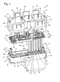
- Fig. 1 shows an electric connection box 10 as a possible embodiment of the invention.
- the electric connection box 10 is of a structure in which an upper case 12 as one case and a lower case 14 as an other case are fit to each other with a bus bar circuit 16 as an internal circuit body being housed within.
- the bus bar circuit 16 is of a structure in which a plurality of bus bars 18 and a plurality of (herein, three) insulating plates 20a through 20c are laminated.
- connection terminals 22a of a so-called tuning fork shape formed of a pair of opposing insulation displacement blades to connect to unillustrated relays as electrical components connection terminals 22b of substantially the same tuning fork shape as the connection terminals 22a to connect to unillustrated fuses as electrical components, connection terminals 22c of substantially a rectangular plate shape to connect to unillustrated connectors as electrical components, and the like are appropriately provided at end portions of the bus bars 18.
- the connection terminals 22a protrude toward the lower case 14 (upward in Fig.
- connection terminals 22b and 22c protrude toward the upper case 12 (downward in Fig. 1 ) in the lamination direction of the insulating plates 20a through 20c.
- a protrusion dimension of the connection terminals 22b from the insulating plates 20a through 20c is greater than a protrusion dimension of the connection terminals 22c protruding in the same direction.
- the respective insulating plates 20a through 20c are of substantially a longitudinal rectangular plate shape all in equal size.
- Each of the insulating plates 20a through 20c is provided with a first insertion hole 24a and a second insertion hole 24b penetrating through the plate in a pair of diagonally located corners.
- the first insertion hole 24a and the second insertion hole 24b are of substantially the same shapes, respectively, as a first positioning recess 45 and a second positioning recess 48 described below.
- the first through holes 24a and the second through-holes 24b provided to the respective insulating plates 20a through 20c coincide with one another and thereby form through-holes penetrating through the insulating plates 20a through 20c in the lamination direction.
- the respective insulating plates 20a through 20c are provided with positioning notches 28 at substantially center portions of edge portions 26 forming short sides all on the same side. As the positioning notches 28 of the respective insulating plates 20a through 20c are brought into coincidence with one another, a notch penetrating through the insulating plates 20a through 20c in the lamination direction is formed.
- the lower case 14 is a single-piece article made of synthetic resin.
- the lower case 14 is provided with a case main body 30 of substantially a longitudinal rectangular box shape opening toward the upper case 12.
- the case main body 30 is formed of a bottom plate 32 of substantially a longitudinal rectangular shape and a circumferential wall 34 protruding toward the upper case 12 from an outer peripheral edge portion of the bottom plate 32. Consequently, when viewed in a direction in which the lower case 14 is fit to the upper case 12 (see Fig. 2 ), the lower case 14 as a whole is of substantially a rotationally symmetric longitudinal rectangular shape.
- a surface of the bottom plate 32 on the outside of the case main body 30 forms an outer surface 35 of the lower case 14.
- the lower case 14 is provided with a plurality of (herein, three) relay attachment portions 36 aligned side by side in a longitudinal direction (left-right direction in Fig. 2 ).
- each relay attachment portion 36 terminal insertion holes 38 in which the connection terminals 22a of the bus bars 18 are inserted are provided so as to penetrate through the bottom plate 32.
- Each relay attachment portion 36 is formed so as to protrude outward (upward in Fig. 4 ) on the outside of the case main body 30 from the bottom plate 32.
- Each relay attachment portion 36 is provided with a pair of opposing protection wall portions 40 and 40 each protruding outward on the outside of the case main body 30 from the bottom plate 32.
- the circumferential wall 34 of a longitudinal rectangular shape is formed of circumferential walls 34a and 34c forming long sides and circumferential walls 34b and 34d forming short sides.
- An engaging recess 41 that becomes concave inward on the inside of the case main body 30 is provided at a center portion of an inner surface of each circumferential wall. Consequently, a locking portion 42 protruding inward on the inside of the case main body 30 from the engaging recess 41 is formed relatively in an outer peripheral portion of the engaging recess 41 on the side of the upper case 12.
- a pair of locking portions 43 and 43 are provided on the outer surfaces of the circumferential walls 34a and 34c on the both sides having the engaging recess 41 in between. Owing to these locking portions 43 and 43, it becomes possible to fix the electric connection box 10 to unillustrated another electric connection box, an unillustrated vehicle body panel or the like.
- the first positioning recess 45 as a positioning recess is formed in a first corner portion 44, which is one of corners opposing in a direction of a diagonal line Lc1 on the bottom plate 32 of substantially a longitudinal rectangular shape
- the second positioning recess 48 as a positioning recess is formed in a second corner portion 46, which is the other corner.
- the first positioning recess 45 is defined by a center hole of a first tube body 50 as a tube body of a bottomed cylindrical shape opening toward the upper case 12 (lower side in Fig. 5B ) and formed in the first corner portion 44 of the bottom plate plate 32.
- the first positioning recess 45 is of a concave shape extending in a direction in which the lower case 14 and the upper case 12 are fit together (top-bottom direction in Fig. 5B ) in substantially a true circular shape in cross section.
- a taper portion 51 expanding toward the upper case 12 is formed continuously along substantially the entire circumference except for inner protrusions 52 and 52 described below. Further, a pair of the inner protrusions 52 and 52 protruding inward on the inside of the first positioning recess 45 are provided to the opening edge portion of the first positioning recess 45 on the side of the upper case 12.
- the inner protrusions 52 and 52 are located oppositely in the diagonal direction Lc1 of the bottom plate 32 and formed in a protruding shape in the opening edge portion of the first positioning recess 45 where the taper portion 51 is provided.
- an inside dimension R1 of the first positioning recess 45 in the direction of the diagonal line Lc1 is defined by a spacing distance between the inner protrusions 52 and 52 in the direction of the diagonal line Lc1.
- the spacing distance between the inner protrusions 52 and 52 is equal to a diameter dimension (dimension in the left-right direction in Fig. 5B ) of the first positioning recess 45 in a portion where the taper portion 51 is not formed and therefore not expanded in diameter by the taper portion 51.
- the second positioning recess 48 is defined by a center hole of a second tube body 54 as a tube body of a bottomed tube shape opening toward the upper case 12 (lower end in Fig. 6(b) ) and provided in a second corner portion 46 (see Fig. 3 ) oppositely to the first tube portion 50 in the direction of the diagonal line Lc1 of the bottom plate 32.
- the second positioning recess 48 is of a concave shape extending in a direction in which the lower case 14 and the upper case 12 are fit together (top-bottom direction in Fig. 6(b) ) in substantially an elliptical shape in cross section having a long axis LI and a short axis Ls.
- the long axis LI extends in the direction of the diagonal line Lc1. Consequently, an inside dimension R2 of the second positioning recess 48 in the direction of the diagonal line Lc1 is defined by the long axis LI and set larger than the inside dimension R1 of the first positioning recess 45 in the direction of the diagonal line Lc1.
- a taper portion 56 expanding toward the upper case 12 is formed continuously along the entire circumference of the second positioning recess 48.
- a pair of guide ribs 58 and 58 are provided on an inner peripheral surface of the second positioning recess 48 so as to protrude inward on the inside of the second positioning recess 48 and extend in an extending direction of the second positioning recess 48 (top-bottom direction in Fig. 6(b) ).
- the guide ribs 58 and 58 are spaced apart in a circumferential direction of the second positioning recess 48.
- a fitting recess groove 60 extending in the extending direction of the second positioning recess 48 is formed between the guide ribs 58 and 58.
- the fitting recess groove 60 is located on the side of the first corner portion 44 (lower left in Fig. 6(a) ) on the long axis LI of the second positioning recess 48. Consequently, as is shown in Fig. 3 , the fitting recess groove 60 and a pair of the inner protrusions 52 and 52 of the first positioning recess 45 are located in a straight line on the diagonal line Lc1.
- the first tube body 50 and the second tube body 54 respectively forming the first positioning recess 45 and the second positioning recess 48 are provided, respectively, in the first corner portion 44 and the second corner portion 46 located in opposing corners of the bottom plate 32 of a longitudinal rectangular shape and therefore spaced apart from each other.
- the first tube body 50 and the second tube body 54 are also provided so as to protrude outward (upward in Fig. 4 ) on the outside of the case main body 30 from the outer surface 35 of the bottom plate 32.
- Protrusion dimensions of the first positioning recess 45 and the second positioning recess 48 from the outer surface 35 are substantially equal to each other and set smaller than a protrusion dimension of the protecting wall portions 40 of the relay attachment portions 36. Also, as is shown in Fig.
- the first tube body 50 corresponds to a shape of the first positioning recess 45 of substantially a true circular shape and is therefore of substantially a true circular shape when viewed in a direction in which the lower case 14 is fit to the upper case 12 (see Fig. 2 ).
- the second tube body 54 corresponds to a shape of the second positioning recess 48 of substantially an elliptical shape and is therefore of substantially an elliptical shape when viewed in the direction in which the lower case 14 is fit to the upper case 12.
- the first tube body 50 and the second tube body 54 have outer shapes different from each other when viewed in the direction in which the lower case 14 is fit to the upper case 12.
- the upper case 12 is a single-piece article made of synthetic resin.
- the upper case 12 is provided with a case main body 62 of substantially a longitudinal rectangular box shape opening toward the lower case 14 (upper side in Fig. 8 ).
- the case main body 62 is formed of a top plate 64 of substantially a longitudinal rectangular shape and a circumferential wall 66 protruding toward the lower case 14 from an outer peripheral edge portion of the top plate 64. Consequently, when viewed in the direction in which the upper case 12 is fit to the lower case 14 (see Fig. 7 ), the upper case 12 as a whole is of substantially a rotational symmetric longitudinal rectangular shape.
- the top plate 64 of the upper case 12 is formed slightly smaller than the bottom plate 32 of the lower case 14 so that the circumferential wall 66 of the upper case 12 is internally inserted into the circumferential wall 34 of the lower case 14.
- the top plate 64 of the upper case 12 is provided with a plurality of (herein, six) fuse attachment portions 68 aligned side by side in a longitudinal direction (left-right direction in Fig. 7 ).
- a pair of terminal insertion holes 70 and 70 in which a pair of the connection terminals 22b and 22b of the bus bars 18 are inserted are provided so as to penetrate through the top plate 64 and oppositely.
- the top plate 64 is provided with a single connector attachment portion 72 adjacently to a plurality of the fuse attachment portions 68 in the longitudinal direction of the top plate 64.
- a plurality of terminal insertion holes 74 in which a plurality of the connection terminals 22c of the bus bars 18 are inserted are provided so as to penetrate through the top plate 64.
- the terminal insertion holes 74 are aligned in two rows in the longitudinal direction of the top plate 64.
- the fuse attachment portions 68 of the electric connection box 10 of this embodiment considerably protrude outward (downward in Fig. 8 ) on the outside of the case main body 62 from the top plate 64.
- the circumferential wall 66 of a longitudinal rectangular shape is formed of circumferential walls 66a and 66c forming long sides and circumferential walls 66b and 66d forming short sides.
- a locking claw 76 is provided so as to protrude at a center of the outer surface of each circumferential wall.
- a pair of pinching pieces 78 and 78 of a hook shape opening toward the lower case 14 are provided to each of the circumferential walls 66a through 66d on the both sides having the locking claw 76 in between.
- a positioning protrusion 80 of a size matching the positioning notches 28 provided to the insulating plates 20a through 20c of the bus bar circuit 16 is provided on the inner surface of the circumferential wall 66b so as to protrude inward on the inside of the case main body 62.
- a first positioning boss 84 as a positioning means is provided in a first corner portion 82 of the top plate 64 of substantially a longitudinal rectangular shape.
- the first corner portion 82 coincides with the first corner portion 44 of the lower case 14 (see Fig. 3 ) when the upper case 12 and the lower case 14 are fit together.
- a second positioning boss 88 as a positioning means is provided in a second corner portion 86 opposing the first corner portion 82 in a direction of a diagonal line Lc2 of the top plate 64.
- the second corner portion 86 coincides with the second corner portion 46 of the lower case 14 when the upper case 12 and the lower case 14 are fit together. Consequently, the first positioning boss 84 and the second positioning boss 88 are provided to the top plate 64 at locations spaced apart from each other diagonally.
- the first positioning boss 84 provided in the first corner portion 82 is of substantially a cylindrical shape protruding from the top plate 64 toward the lower case 14 (upper side in Fig. 8 ) while maintaining substantially a constant outside diameter dimension.
- a plurality of rattling preventing ribs 90 are provided on an outer peripheral surface of the first positioning boss 84.
- the rattling preventing ribs 90 are provided at regular intervals in a circumferential direction and so as to protrude radially outward on the outside of the first positioning boss 84.
- four rattling preventing ribs 90a through 90d are provided in every 90° about a center axis of the first positioning boss 84.
- a pair of the rattling preventing ribs 90a and 90c are provided on the outside of the first positioning boss 84 on the both sides in a radial direction so as to protrude in the direction of the diagonal line Lc2.
- Protrusion dimensions D1a through D1d of the rattling preventing ribs 90a through 90d, respectively, from the outer peripheral surface of the first positioning boss 84 are all set to be equal.
- Protrusion tip edge portions of the rattling preventing ribs 90a through 90d from the outer peripheral surface of the first positioning boss 84 are set to a size allowing the protrusion tip edge portions to be inscribed in a circle C1 having a diameter of R1 and corresponding to a sectional shape of the first positioning recess 45.
- the first positioning boss 84 extends from the top plate 64 in a cylindrical shape having an outside diameter smaller than the inside dimension R1 of the first positioning recess 45 in a portion where the rattling ribs 90a through 90d are not provided.
- the rattling preventing ribs 90a through 90d are provided substantially fully along the first positioning boss 84 in an extending direction (top-bottom direction in Fig. 8 ).
- a taper surface 92 is provided to each of the protrusion tip edge portions of the respective rattling preventing ribs 90a through 90d from the top plate 64.
- a protrusion dimension of the taper surface 92 from the outer peripheral surface of the first positioning boss 84 reduces gradually toward the tip end in the protruding direction (upward in Fig. 8 ). It thus becomes easy to insert the first positioning boss 84 into the first positioning recess 45.
- the second positioning boss 88 provided in the second corner portion 86 protrudes toward the lower case 14 (upper side in Fig. 8 ) from the top plate 64 in substantially a cylindrical shape having an outside diameter dimension substantially equal to that of the first positioning boss 84.
- a pair of rib protrusions 94a and 94b and a pair of rattling preventing ribs 96a and 96b each protruding radially outward on the outside of the second positioning boss 88 are provided on an outer peripheral surface of the second positioning boss 88 at predetermined intervals in the circumferential direction.
- the rib protrusions 94a and 94b and the rattling preventing ribs 96a and 96b are provided alternately in every 90° about a center axis of the second positioning boss 88.
- the rib protrusions 94a and 94b are provided on the outside of the second positioning boss 88 on the both sides in a radial direction so as to protrude in the direction of the diagonal line Lc2.
- the rattling preventing ribs 96a and 96b are provided on the outside of the second positioning boss 88 on the both sides in a radial direction so as to protrude in a direction orthogonal to the diagonal line Lc2. Consequently, as is shown in Fig.
- the rib protrusions 94a and 94b of the second positioning rib 88 and the rattling preventing ribs 90a and 90c of the first positioning boss 84 are provided in a straight line on the diagonal line Lc2.
- Protrusion dimensions D2a and D2b of the rib protrusions 94a and 94b, respectively, from the outer peripheral surface of the second positioning boss 88 are set to be equal to each other.
- protrusion dimensions D2c and D2d of the rattling preventing ribs 96a and 96b, respectively, from the outer peripheral surface of the second positioning boss 88 are set to be equal to each other.
- the protrusion dimensions D2a and D2b of the rib protrusions 94a and 94b, respectively, are set larger than the protrusion dimensions D2c and D2d of the rattling preventing ribs 96a and 96b, respectively. Consequently, the protrusion tip edge portions of the rattling preventing ribs 96a and 96b are inscribed in an oval C2 having a long axis LI and a short axis Ls and corresponding to a sectional shape of the second positioning recess 48 in a direction of the short axis Ls. Meanwhile, the protrusion tip edge portions of the rib protrusions 94a and 94b are set to a size to be located on slightly inner side from the oval C2 in a direction of the long axis LI.
- the rib protrusions 94a and 94b and the rattling preventing ribs 96a and 96b are formed substantially fully along the second positioning boss 88 in an extending direction (top-bottom direction in Fig. 8 ).
- a taper surface 98 is provided to each of the protrusion tip edge portions of the respective rib protrusions 94a and 94b and rattling preventing ribs 96a and 96b from the top plate 64.
- a protrusion dimension of the taper surface 98 from the outer peripheral surface of the second positioning boss 88 reduces gradually toward the tip end in the protruding direction (upward in Fig. 8 ).
- the taper surface 98a of the rib protrusion 94b located on the outer side of the upper case 12 in the direction of the diagonal line Lc2 is formed longer than the other taper surfaces 98 of the rib protrusion 94a and the rattling preventing ribs 96a and 96b in the extending direction of the second positioning boss 88 (top-bottom direction in Fig. 8 ).
- this taper surface 98 starts to exert a guiding function on the second positioning recess 48 in an outer portion of the second positioning boss 88 in the direction of the diagonal line Lc2 in an early stage. It thus becomes possible to more effectively absorb a dimensional error between the upper case 12 and the lower case 14.
- protrusion heights H1 and H2 of the first positioning boss 84 and the second positioning boss 88, respectively, from a tip end portion 100 of the circumferential wall 66 toward the lower case 14 are set to sizes equal to each other.
- the protrusion heights H1 and H2 of the first positioning boss 84 and the second positioning boss 88, respectively are set higher than a protrusion height H3 of the connection terminals 22a of the bus bar circuit 16 from the tip end portion 100 toward the lower case 14.
- a plurality of the bus bars 18 and a plurality of the insulating plates 20a through 20c are laminated first to form the bus bar circuit 16.
- the upper case 12 is located vertically below the bus bar circuit 16.
- the connection terminals 22b and 22c protruding from the insulating plate 20a of the bus bar circuit 16 are inserted, respectively, into the terminal insertion holes 70 and 74 of the upper case 12.
- the first positioning boss 84 and the second positioning boss 88 are inserted, respectively, into the first insertion holes 24a and the second insertion holes 24b of the insulating plates 20a through 20c.
- the insulating plates 20a through 20c are thus housed within the case main body 62 of the upper case 12.
- the insulating plates 20a through 20c can be positioned with accuracy within the case main body 62 as the positioning notches 28 and the positioning protrusion 80 of the upper case 12 are engaged with each other.
- the lower case 14 is placed on the upper case 12 from above in a vertical direction, so that the first positioning boss 84 of the upper case 12 is fit into the first positioning recess 45 of the lower case 14 while the second positioning boss 88 is fit into the second positioning recess 48.
- the lower case 14 is placed on the upper case 12.
- the upper case 12 and the lower case 14 are fit together in such a manner that the circumferential wall 34 of the lower case 14 is inserted on the outer peripheral side of the circumferential wall 66 of the upper case 12 while the circumferential wall 34 of the lower case 14 is pinched between the pinching pieces 78 and the circumferential wall 66 of the upper case 12.
- the locking claws 76 of the upper case 12 go into the engaging recesses 41 formed in the inner surface of the circumferential wall 34 of the lower case 14.
- the locking portions 42 on the outer peripheral side of the engaging recesses 41 and the locking claws 76 are engaged with each other, the upper case 12 and the lower case 14 are fit to each other in a locked state.
- the electric connection box 10 is thus formed.
- the hollow case 102 of a rectangular shape is formed by fitting the case main body 62 of the upper case 12 and the case main body 30 of the lower case 14 both of a longitudinal rectangular box shape to each other while the upper case 12 and the lower case 14 are fit to each other.
- the bus bar circuit 16 is housed in the interior of the hollow case 102 while the insulating plates 20a through 20c of the bus bar circuit 16 are sandwiched between the upper case 12 and the lower case 14.
- connection terminals 22a of the bus bar circuit 16 are inserted into the terminal insertion holes 38 of the relay attachment portions 36 to protrude into an outside space of the hollow case 102 while the connection terminals 22b and 22c are inserted, respectively, into the terminal insertion holes 70 of the fuse attachment portions 68 and the terminal insertion holes 74 of the connector attachment portion 72 to protrude into the outside space of the hollow case 102.
- the first positioning boss 84 is inserted into the first positioning recess 45 in such a manner that there is substantially no clearance between the four rattling preventing ribs 94a through 90d and the inner peripheral surface of the first positioning recess 45.
- the second positioning boss 88 is positioned in the circumferential direction by the rib protrusions 94a and 94b as the rib protrusion 94a located on the inner side of the hollow case 102 in the direction of the diagonal line Lc2 (see Fig. 7 ) is fit into the fitting recess groove 60.
- the rattling preventing ribs 96a and 96b are located in the direction of the short axis Ls of the second positioning recess 48.
- the second positioning boss 88 is inserted into the second positioning recess 48 in such a manner that there is substantially no clearance between the rattling preventing ribs 96a and 96b and the inner peripheral surface of the second positioning recess 48.
- the rib protrusion 94a and 94b are located in the direction of the long axis LI of the second positioning recess 48, which is the direction of the diagonal line Lc2.
- the second positioning boss 88 is inserted into the second positioning recess 48 in such a manner that there is a slight clearance between the rib protrusions 94a and 94b and the inner peripheral surface of the second positioning recess 48.
- the first tube body 50 and the second tube body 54 defining the first positioning recess 45 and the second positioning recess 48, respectively, of the lower case 14 protrude on the outer surface 35 of the lower case 14 and are therefore visually recognizable from the outside of the lower case 14. Consequently, when the lower case 14 is fit to the upper case 12, it becomes possible to find the locations of the first positioning recess 45 and the second positioning recess 48 easily using the first tube body 50 and the second tube body 54 as guiding marks. Accordingly, it becomes possible to easily perform a work to insert the first positioning boss 84 and the second positioning boss 88 of the upper case 12 into the first positioning recess 45 and the second positioning recess 48, respectively.
- the first tube body 50 is of substantially a true circular shape whereas the second tube body 54 is of substantially an oval shape. That is, the outer shapes are different from each other.
- the upper case 12 and the lower case 14 are of substantially a longitudinal rectangular shape when viewed in a direction in which the upper case 12 and the lower case 14 are fit together and each remains in substantially the same shape in a 180°-rotated state, it becomes possible to easily find an assembling direction on the basis of the locations of the first tube body 50 and the second tube body 54 by distinguishing between the first tube body 50 and the second tube body 54.
- the first tube body 50 and the second tube body 54 are provided so as to protrude on the outer surface 35 of the lower case 14, a protrusion dimension of the first tube body 50 and the second tube body 54 can be secured on the outside of the lower case 14.
- the protrusion height of the first tube body 50 and the second tube body 54 from the outer surface 35 is set to fall within the protrusion height of the protection wall portions 40 of the relay attachment portions 36.
- an amount of protrusion of the first tube body 50 and the second tube body 54 from the outer surface 35 does not exceed that of the existing relay attachment portions 36. Accordingly, the electric connection box 10 can be compact in a more sophisticated manner.
- first tube body 50 and the second tube body 54 are provided so as to protrude from the bottom plate 32 of the lower case 14, it becomes possible to provide the first positioning boss 84 and the second positioning boss 88 of the upper case 12 to be inserted into the first tube body 50 and the second tube body 54, respectively, with a protrusion height dimension from the circumferential wall 66 of the upper case 12 larger than a protrusion height dimension of the connection terminals 22a.
- the first positioning boss 84 and the second positioning boss 88 to be inserted into the first tube body 50 and the second tube body 54, respectively, are not allowed to protrude beyond the bottom plate 32. It therefore becomes difficult to provide the first positioning boss 84 and the second positioning boss 88 with an amount of protrusion larger than that of the connection terminals 22a protruding from the bottom plate 32.
- the first positioning boss 84 and the second positioning boss 88 of the upper case 12 are allowed to protrude toward the lower case 14 with a protrusion height dimension larger than that of the connection terminals 22a. Consequently, when the lower case 14 is fit to the upper case 12, the lower case 14 is positioned with respect to the upper case 12 by fitting the first positioning boss 84 and the second positioning boss 88 into the first positioning recess 45 and the second positioning recess 48, respectively, before the connection terminals 22a are inserted into the terminal insertion holes 38 of the lower case 14. It thus becomes possible to position the connection terminals 22a with respect to the terminal insertion holes 38 and then insert the former into the latter. The operator therefore becomes able to perform an assembling work more easily in a reliable manner.
- positioning recesses and the positioning bosses are not limited to a circular shape including an elliptical shape and an oval shape, and a rectangular shape, a polygonal shape, and other various shapes can be also suitably adopted as the sectional shape.
- the numbers of the positioning recesses and the positioning bosses are not limited, either, and three or more positioning recesses and positioning bosses may be provided.
- one case and an other case are positioned with respect to each other by fitting positioning bosses provided to the one case, respectively, into positioning recesses provided to the other case.
- tube bodies defining the positioning recesses, respectively are provided so as to protrude on an outer surface of the other case.
Landscapes
- Engineering & Computer Science (AREA)
- Architecture (AREA)
- Civil Engineering (AREA)
- Structural Engineering (AREA)
- Connection Or Junction Boxes (AREA)
- Casings For Electric Apparatus (AREA)
Abstract
Description
- The present invention relates to an electric connection box installed to an automobile or the like, and more particularly, to an electric connection box including a hollow case formed by fitting one case and an other case together and an internal circuit body housed within the hollow case. Reference is herewith explicitly made to the co-pending two other applications of the same Applicant and of the same day having both the title "ELECTRIC CONNECTION BOX" (Attorneys file Nos.
SU5797/56 SU5799/56 - An electric connection box in the related art adopts a configuration in which a hollow case is formed by fitting one case and an other case, such as an upper case and a lower case, to each other on the sides of opening portions and an internal circuit body formed of bus bars and the like is housed within the hollow case. By inserting connection terminals provided to the internal circuit body into terminal insertion holes provided so as to penetrate through the hollow case, fuses to be connected to the connection terminals, a connector connected to an end portion of an outside electric wire, and the like are connected to the internal circuit body.
- Incidentally, with the electric connection box as above, it is necessary to form the hollow case by fitting the other case to the one case while the internal circuit body is housed in the one case. Hence, when the one case and the other case are fit together, it is crucial that the one case and the other case are positioned precisely with respect to each other. To this end, there has been proposed a structure in which, as are shown in
Fig. 2, Fig. 3 ,Fig. 10 , andFig. 12 ofJP-A-2010-110060 - However, in the structure in the related art described in
JP-A-2010-110060 - Also, the positioning recess is provided to the interior of the other case. Hence, it is difficult for an operator to confirm the location of the positioning recess during an assembling work. Accordingly, there is a problem that a work to position the positioning recess with respect to the positioning boss is by no means easy and takes a time. In a case where the worker fails to fit the positioning boss into the positioning recess successfully, the connection terminals cannot be inserted into the terminal insertion holes and there is a risk that the connection terminals abut on the other case and become deformed.
- The invention was devised in view of the foregoing circumstances and has an object to provide an electric connection box of a novel structure facilitating a work to position a positioning boss provided to one case with respect to a positioning recess provided to the other case while achieving a more compact size.
- According to a first aspect of the invention, an electric connection box is configured in such a manner that an internal circuit body is housed within a hollow case formed by fitting one case and an other case together and the one case is positioned with respect to the other case by means of at least one positioning boss provided to an interior of the one case, which is fit into a positioning recess provided to an interior of the other case so that a connection terminal provided to the internal circuit body is inserted into a terminal insertion hole provided so as to penetrate through the hollow case. The electric connection box is characterized in that a tube body defining the positioning recess is provided so as to protrude on an outer surface of the other case.
- In the electric connection box of the structure according to the invention, the tube body defining the positioning recess in which the positioning boss provided to the one case is fit is provided so as to protrude on the outer surface of the other case. Consequently, the tube body is visibly recognizable from the outer surface of the other case. Accordingly, a worker who fits the one case and the other case together becomes able to find a location at which the positioning recess is provided from the outer surface of the other case easily in a reliable manner and therefore becomes able to perform a work to position the positioning boss with respect to the positioning recess easily in a reliable manner. It thus becomes possible to enhance and stabilize workability in assembling the electric connection box.
- Moreover, by providing the tube body defining the positioning recess so as to protrude on the outer surface of the other case, a protrusion dimension of the tube body can be secured on the outside of the case. Consequently, in comparison with the structure in the related art in which the tube body defining the positioning recess is provided so as to protrude in the interior of the case, it becomes possible to lessen an increase in thickness and size of the other case and hence of the electric connection box. The electric connection box can be therefore more compact. In particular, electrical component attachment portions, such as fuse attachment portions and connector attachment portions, are provided so as to protrude on the outer surface of the electric connection box. Hence, by setting the protrusion height of the tube potion to fall within a protrusion height of these electrical component attachment portions, it becomes possible to provide the positioning recess without increasing the electric connection box in thickness and size. Hence, it becomes possible to increase a degree of freedom in design.
- Preferably, the electric connection box according to the present invention is configured in such a manner that the positioning boss and the positioning recess are provided in two places spaced apart from each other, and that an outer shape of the tube body defining the positioning recess in one place and an outer shape of the tube body defining the positioning recess in the other place are different from each other.
- According to this aspect, because the outer shapes of the tube bodies provided in the two places of the other case are different from each other, it becomes possible to distinguish between the two tube bodies and use the tube bodies as a guiding mark of a direction in which the other case is fit to the one case. Hence, for example, in a case where the other case has an assembling orientation but is also of substantially a left-right and top-bottom symmetrical outer shape, by providing mutually different outer shapes to the tube portions provided in two places spaced apart from each other, it becomes possible to provide the tube portions to also serve as a guiding mark of the assembling direction.
- Preferably, the electric connection box according to the present invention is furthermore configured in such a manner that the one case and the other case are fit together by inserting a circumferential wall of the other case on an outer peripheral side of a circumferential wall of the one case to overlap each other; the internal circuit body is housed in the interior of the one case; and the positioning boss protrudes from a tip end portion of the circumferential wall of the one case toward the other case with a protrusion height higher than a protrusion height of the connection terminal.
- In the invention, the tube body defining the positioning recess is provided so as to protrude on the outer surface of the other case. Consequently, it becomes possible to provide the positioning boss to the one case to protrude in such a manner that a protrusion height from a tip end portion of the circumferential wall is set higher than the protrusion height of the connection terminal. Hence, it becomes possible to form a guiding mechanism that prevents the connection terminal from coming into the other case during a work to fit the one case and the other case together using the positioning boss. Hence, the connection terminal can be protected further advantageously. More specifically, as is shown in
Fig. 12 ofJP-A-2010-110060 - In the invention, the tube body defining the positioning recess in which the positioning boss provided to the one case in the form of a protrusion is fit is provided so as to protrude on the outer surface of the other case. Hence, it becomes possible to find the location of the positioning recess from the outside of the other case easily using the tube body as a guiding mark. It thus becomes possible to perform a work to position the positioning boss with respect to the positioning recess easily. Further, by securing a protrusion dimension of the tube body on the outside of the other case, it becomes possible to avoid an increase in thickness and size of the other case and hence of the electric connection box in comparison with a case where the protrusion dimension of the tube body is secured in the interior of the other case. The electric connection box can therefore become more compact.
- The invention now will be more fully described by means of an illustrative but not limiting embodiment thereof in conjunction with the accompanying drawings, in which:
-
Fig. 1 is an exploded perspective view of an electric connection box according to one embodiment of the invention; -
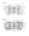
Fig. 2 is a bottom view of a lower case; -
Fig. 3 is a plan view of the lower case; -
Fig. 4 is a side view of the lower case; -
Fig. 5(a) is an enlarged view of a first positioning recess andFig. 5(b) is a cross section taken along the line Vb-Vb ofFig. 5(a) ; -
Fig. 6(a) is an enlarged view of a second positioning recess andFig. 6(b) is a cross section taken along the line VIb-VIb ofFig. 6(a) ; -
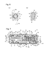
Fig. 7 is a bottom view of an upper case; -
Fig. 8 is a side view of the upper case; -
Fig. 9 is an enlarged view of a first positioning boss; -
Fig. 10 is an enlarged view of a second positioning boss; -
Fig. 11 is a cross section taken along the line XI-XI ofFig. 2 of the electric connection box shown inFig. 1 in an assembled state; and -
Fig. 12(a) is a view used to describe a fit-in state of the first positioning boss in the first positioning recess andFig. 12(b) is a view used to describe a fit-in state of the second positioning boss in the second positioning recess. - Hereinafter, an embodiment of the invention will be described with reference to the drawings.
- Firstly,
Fig. 1 shows anelectric connection box 10 as a possible embodiment of the invention. Theelectric connection box 10 is of a structure in which anupper case 12 as one case and alower case 14 as an other case are fit to each other with abus bar circuit 16 as an internal circuit body being housed within. - The
bus bar circuit 16 is of a structure in which a plurality ofbus bars 18 and a plurality of (herein, three) insulatingplates 20a through 20c are laminated. As in the related art,connection terminals 22a of a so-called tuning fork shape formed of a pair of opposing insulation displacement blades to connect to unillustrated relays as electrical components,connection terminals 22b of substantially the same tuning fork shape as theconnection terminals 22a to connect to unillustrated fuses as electrical components,connection terminals 22c of substantially a rectangular plate shape to connect to unillustrated connectors as electrical components, and the like are appropriately provided at end portions of the bus bars 18. Theconnection terminals 22a protrude toward the lower case 14 (upward inFig. 1 ) in a lamination direction of the laminated insulatingplates 20a through 20c whereas theconnection terminals Fig. 1 ) in the lamination direction of the insulatingplates 20a through 20c. A protrusion dimension of theconnection terminals 22b from the insulatingplates 20a through 20c is greater than a protrusion dimension of theconnection terminals 22c protruding in the same direction. - The respective insulating
plates 20a through 20c are of substantially a longitudinal rectangular plate shape all in equal size. Each of the insulatingplates 20a through 20c is provided with afirst insertion hole 24a and asecond insertion hole 24b penetrating through the plate in a pair of diagonally located corners. Thefirst insertion hole 24a and thesecond insertion hole 24b are of substantially the same shapes, respectively, as afirst positioning recess 45 and asecond positioning recess 48 described below. When the respective insulatingplates 20a through 20c are laminated one on another, the first throughholes 24a and the second through-holes 24b provided to the respective insulatingplates 20a through 20c coincide with one another and thereby form through-holes penetrating through the insulatingplates 20a through 20c in the lamination direction. Further, the respective insulatingplates 20a through 20c are provided with positioning notches 28 at substantially center portions ofedge portions 26 forming short sides all on the same side. As the positioning notches 28 of the respective insulatingplates 20a through 20c are brought into coincidence with one another, a notch penetrating through the insulatingplates 20a through 20c in the lamination direction is formed. -
Fig. 2 through Fig. 4 show thelower case 14. Thelower case 14 is a single-piece article made of synthetic resin. Thelower case 14 is provided with a casemain body 30 of substantially a longitudinal rectangular box shape opening toward theupper case 12. The casemain body 30 is formed of abottom plate 32 of substantially a longitudinal rectangular shape and a circumferential wall 34 protruding toward theupper case 12 from an outer peripheral edge portion of thebottom plate 32. Consequently, when viewed in a direction in which thelower case 14 is fit to the upper case 12 (seeFig. 2 ), thelower case 14 as a whole is of substantially a rotationally symmetric longitudinal rectangular shape. In addition, a surface of thebottom plate 32 on the outside of the casemain body 30 forms anouter surface 35 of thelower case 14. - The
lower case 14 is provided with a plurality of (herein, three)relay attachment portions 36 aligned side by side in a longitudinal direction (left-right direction inFig. 2 ). In eachrelay attachment portion 36, terminal insertion holes 38 in which theconnection terminals 22a of the bus bars 18 are inserted are provided so as to penetrate through thebottom plate 32. Eachrelay attachment portion 36 is formed so as to protrude outward (upward inFig. 4 ) on the outside of the casemain body 30 from thebottom plate 32. Eachrelay attachment portion 36 is provided with a pair of opposingprotection wall portions main body 30 from thebottom plate 32. - Also, as are shown in
Fig. 3 andFig. 4 , the circumferential wall 34 of a longitudinal rectangular shape is formed ofcircumferential walls circumferential walls recess 41 that becomes concave inward on the inside of the casemain body 30 is provided at a center portion of an inner surface of each circumferential wall. Consequently, a lockingportion 42 protruding inward on the inside of the casemain body 30 from the engagingrecess 41 is formed relatively in an outer peripheral portion of the engagingrecess 41 on the side of theupper case 12. Further, a pair of lockingportions circumferential walls recess 41 in between. Owing to these lockingportions electric connection box 10 to unillustrated another electric connection box, an unillustrated vehicle body panel or the like. - As is shown in
Fig. 3 , in the interior of thelower case 14, thefirst positioning recess 45 as a positioning recess is formed in afirst corner portion 44, which is one of corners opposing in a direction of a diagonal line Lc1 on thebottom plate 32 of substantially a longitudinal rectangular shape, and thesecond positioning recess 48 as a positioning recess is formed in asecond corner portion 46, which is the other corner. As is also shown inFig. 5 , thefirst positioning recess 45 is defined by a center hole of afirst tube body 50 as a tube body of a bottomed cylindrical shape opening toward the upper case 12 (lower side inFig. 5B ) and formed in thefirst corner portion 44 of thebottom plate plate 32. Thefirst positioning recess 45 is of a concave shape extending in a direction in which thelower case 14 and theupper case 12 are fit together (top-bottom direction inFig. 5B ) in substantially a true circular shape in cross section. - In an opening edge portion of the
first positioning recess 45 on the side of theupper case 12, ataper portion 51 expanding toward theupper case 12 is formed continuously along substantially the entire circumference except forinner protrusions inner protrusions first positioning recess 45 are provided to the opening edge portion of thefirst positioning recess 45 on the side of theupper case 12. Theinner protrusions bottom plate 32 and formed in a protruding shape in the opening edge portion of thefirst positioning recess 45 where thetaper portion 51 is provided. Consequently, an inside dimension R1 of thefirst positioning recess 45 in the direction of the diagonal line Lc1 is defined by a spacing distance between theinner protrusions inner protrusions Fig. 5B ) of thefirst positioning recess 45 in a portion where thetaper portion 51 is not formed and therefore not expanded in diameter by thetaper portion 51. - Meanwhile, as is also shown in
Fig. 6 , thesecond positioning recess 48 is defined by a center hole of asecond tube body 54 as a tube body of a bottomed tube shape opening toward the upper case 12 (lower end inFig. 6(b) ) and provided in a second corner portion 46 (seeFig. 3 ) oppositely to thefirst tube portion 50 in the direction of the diagonal line Lc1 of thebottom plate 32. Thesecond positioning recess 48 is of a concave shape extending in a direction in which thelower case 14 and theupper case 12 are fit together (top-bottom direction inFig. 6(b) ) in substantially an elliptical shape in cross section having a long axis LI and a short axis Ls. The long axis LI extends in the direction of the diagonal line Lc1. Consequently, an inside dimension R2 of thesecond positioning recess 48 in the direction of the diagonal line Lc1 is defined by the long axis LI and set larger than the inside dimension R1 of thefirst positioning recess 45 in the direction of the diagonal line Lc1. - In an opening edge portion of the
second positioning recess 48 on the side of theupper case 12, ataper portion 56 expanding toward theupper case 12 is formed continuously along the entire circumference of thesecond positioning recess 48. Further, a pair ofguide ribs second positioning recess 48 so as to protrude inward on the inside of thesecond positioning recess 48 and extend in an extending direction of the second positioning recess 48 (top-bottom direction inFig. 6(b) ). Theguide ribs second positioning recess 48. Consequently, afitting recess groove 60 extending in the extending direction of thesecond positioning recess 48 is formed between theguide ribs fitting recess groove 60 is located on the side of the first corner portion 44 (lower left inFig. 6(a) ) on the long axis LI of thesecond positioning recess 48. Consequently, as is shown inFig. 3 , thefitting recess groove 60 and a pair of theinner protrusions first positioning recess 45 are located in a straight line on the diagonal line Lc1. - The
first tube body 50 and thesecond tube body 54 respectively forming thefirst positioning recess 45 and thesecond positioning recess 48 are provided, respectively, in thefirst corner portion 44 and thesecond corner portion 46 located in opposing corners of thebottom plate 32 of a longitudinal rectangular shape and therefore spaced apart from each other. Thefirst tube body 50 and thesecond tube body 54 are also provided so as to protrude outward (upward inFig. 4 ) on the outside of the casemain body 30 from theouter surface 35 of thebottom plate 32. Protrusion dimensions of thefirst positioning recess 45 and thesecond positioning recess 48 from theouter surface 35 are substantially equal to each other and set smaller than a protrusion dimension of the protectingwall portions 40 of therelay attachment portions 36. Also, as is shown inFig. 2 , thefirst tube body 50 corresponds to a shape of thefirst positioning recess 45 of substantially a true circular shape and is therefore of substantially a true circular shape when viewed in a direction in which thelower case 14 is fit to the upper case 12 (seeFig. 2 ). Meanwhile, thesecond tube body 54 corresponds to a shape of thesecond positioning recess 48 of substantially an elliptical shape and is therefore of substantially an elliptical shape when viewed in the direction in which thelower case 14 is fit to theupper case 12. In this manner, thefirst tube body 50 and thesecond tube body 54 have outer shapes different from each other when viewed in the direction in which thelower case 14 is fit to theupper case 12. -
Fig. 7 andFig. 8 show theupper case 12. Theupper case 12 is a single-piece article made of synthetic resin. Theupper case 12 is provided with a casemain body 62 of substantially a longitudinal rectangular box shape opening toward the lower case 14 (upper side inFig. 8 ). The casemain body 62 is formed of atop plate 64 of substantially a longitudinal rectangular shape and acircumferential wall 66 protruding toward thelower case 14 from an outer peripheral edge portion of thetop plate 64. Consequently, when viewed in the direction in which theupper case 12 is fit to the lower case 14 (seeFig. 7 ), theupper case 12 as a whole is of substantially a rotational symmetric longitudinal rectangular shape. Thetop plate 64 of theupper case 12 is formed slightly smaller than thebottom plate 32 of thelower case 14 so that thecircumferential wall 66 of theupper case 12 is internally inserted into the circumferential wall 34 of thelower case 14. - The
top plate 64 of theupper case 12 is provided with a plurality of (herein, six)fuse attachment portions 68 aligned side by side in a longitudinal direction (left-right direction inFig. 7 ). In eachfuse attachment portion 68, a pair of terminal insertion holes 70 and 70 in which a pair of theconnection terminals top plate 64 and oppositely. Also, thetop plate 64 is provided with a singleconnector attachment portion 72 adjacently to a plurality of thefuse attachment portions 68 in the longitudinal direction of thetop plate 64. In theconnector attachment portion 72, a plurality of terminal insertion holes 74 in which a plurality of theconnection terminals 22c of the bus bars 18 are inserted are provided so as to penetrate through thetop plate 64. The terminal insertion holes 74 are aligned in two rows in the longitudinal direction of thetop plate 64. Thefuse attachment portions 68 of theelectric connection box 10 of this embodiment considerably protrude outward (downward inFig. 8 ) on the outside of the casemain body 62 from thetop plate 64. - Also, the
circumferential wall 66 of a longitudinal rectangular shape is formed ofcircumferential walls circumferential walls claw 76 is provided so as to protrude at a center of the outer surface of each circumferential wall. Also, a pair of pinchingpieces lower case 14 are provided to each of thecircumferential walls 66a through 66d on the both sides having the lockingclaw 76 in between. Further, apositioning protrusion 80 of a size matching the positioning notches 28 provided to the insulatingplates 20a through 20c of thebus bar circuit 16 is provided on the inner surface of thecircumferential wall 66b so as to protrude inward on the inside of the casemain body 62. - In the interior of the
upper case 12, afirst positioning boss 84 as a positioning means is provided in afirst corner portion 82 of thetop plate 64 of substantially a longitudinal rectangular shape. Thefirst corner portion 82 coincides with thefirst corner portion 44 of the lower case 14 (seeFig. 3 ) when theupper case 12 and thelower case 14 are fit together. Also, in the interior of theupper case 12, asecond positioning boss 88 as a positioning means is provided in asecond corner portion 86 opposing thefirst corner portion 82 in a direction of a diagonal line Lc2 of thetop plate 64. Thesecond corner portion 86 coincides with thesecond corner portion 46 of thelower case 14 when theupper case 12 and thelower case 14 are fit together. Consequently, thefirst positioning boss 84 and thesecond positioning boss 88 are provided to thetop plate 64 at locations spaced apart from each other diagonally. - The
first positioning boss 84 provided in thefirst corner portion 82 is of substantially a cylindrical shape protruding from thetop plate 64 toward the lower case 14 (upper side inFig. 8 ) while maintaining substantially a constant outside diameter dimension. As is shown inFig. 9 , a plurality of rattling preventing ribs 90 are provided on an outer peripheral surface of thefirst positioning boss 84. The rattling preventing ribs 90 are provided at regular intervals in a circumferential direction and so as to protrude radially outward on the outside of thefirst positioning boss 84. In this embodiment, four rattling preventingribs 90a through 90d are provided in every 90° about a center axis of thefirst positioning boss 84. A pair of the rattling preventingribs first positioning boss 84 on the both sides in a radial direction so as to protrude in the direction of the diagonal line Lc2. Protrusion dimensions D1a through D1d of the rattling preventingribs 90a through 90d, respectively, from the outer peripheral surface of thefirst positioning boss 84 are all set to be equal. Protrusion tip edge portions of the rattling preventingribs 90a through 90d from the outer peripheral surface of thefirst positioning boss 84 are set to a size allowing the protrusion tip edge portions to be inscribed in a circle C1 having a diameter of R1 and corresponding to a sectional shape of thefirst positioning recess 45. Consequently, thefirst positioning boss 84 extends from thetop plate 64 in a cylindrical shape having an outside diameter smaller than the inside dimension R1 of thefirst positioning recess 45 in a portion where the rattlingribs 90a through 90d are not provided. In addition, the rattling preventingribs 90a through 90d are provided substantially fully along thefirst positioning boss 84 in an extending direction (top-bottom direction inFig. 8 ). As is shown inFig. 9 , ataper surface 92 is provided to each of the protrusion tip edge portions of the respectiverattling preventing ribs 90a through 90d from thetop plate 64. A protrusion dimension of thetaper surface 92 from the outer peripheral surface of thefirst positioning boss 84 reduces gradually toward the tip end in the protruding direction (upward inFig. 8 ). It thus becomes easy to insert thefirst positioning boss 84 into thefirst positioning recess 45. - Meanwhile, the
second positioning boss 88 provided in thesecond corner portion 86 protrudes toward the lower case 14 (upper side inFig. 8 ) from thetop plate 64 in substantially a cylindrical shape having an outside diameter dimension substantially equal to that of thefirst positioning boss 84. As is shown inFig. 10 , a pair ofrib protrusions ribs second positioning boss 88 are provided on an outer peripheral surface of thesecond positioning boss 88 at predetermined intervals in the circumferential direction. In this embodiment, therib protrusions rattling preventing ribs second positioning boss 88. Therib protrusions second positioning boss 88 on the both sides in a radial direction so as to protrude in the direction of the diagonal line Lc2. Also, the rattling preventingribs second positioning boss 88 on the both sides in a radial direction so as to protrude in a direction orthogonal to the diagonal line Lc2. Consequently, as is shown inFig. 7 , therib protrusions second positioning rib 88 and therattling preventing ribs first positioning boss 84 are provided in a straight line on the diagonal line Lc2. Protrusion dimensions D2a and D2b of therib protrusions second positioning boss 88 are set to be equal to each other. Also, protrusion dimensions D2c and D2d of the rattling preventingribs second positioning boss 88 are set to be equal to each other. The protrusion dimensions D2a and D2b of therib protrusions ribs ribs second positioning recess 48 in a direction of the short axis Ls. Meanwhile, the protrusion tip edge portions of therib protrusions - Also, the
rib protrusions rattling preventing ribs second positioning boss 88 in an extending direction (top-bottom direction inFig. 8 ). As is shown inFig. 10 , ataper surface 98 is provided to each of the protrusion tip edge portions of therespective rib protrusions ribs top plate 64. A protrusion dimension of thetaper surface 98 from the outer peripheral surface of thesecond positioning boss 88 reduces gradually toward the tip end in the protruding direction (upward inFig. 8 ). It thus becomes easy to insert thesecond positioning boss 88 into thesecond positioning recess 48. In particular, thetaper surface 98a of therib protrusion 94b located on the outer side of theupper case 12 in the direction of the diagonal line Lc2 is formed longer than the other taper surfaces 98 of therib protrusion 94a and therattling preventing ribs Fig. 8 ). Hence, this taper surface 98 starts to exert a guiding function on thesecond positioning recess 48 in an outer portion of thesecond positioning boss 88 in the direction of the diagonal line Lc2 in an early stage. It thus becomes possible to more effectively absorb a dimensional error between theupper case 12 and thelower case 14. - As is shown in
Fig. 8 , protrusion heights H1 and H2 of thefirst positioning boss 84 and thesecond positioning boss 88, respectively, from atip end portion 100 of thecircumferential wall 66 toward the lower case 14 (upper side inFig. 8 ) are set to sizes equal to each other. In a state where thebus bar circuit 16 is housed in theupper case 12, the protrusion heights H1 and H2 of thefirst positioning boss 84 and thesecond positioning boss 88, respectively, are set higher than a protrusion height H3 of theconnection terminals 22a of thebus bar circuit 16 from thetip end portion 100 toward thelower case 14. - When the
electric connection box 10 as above is assembled, as is shown inFig. 1 , a plurality of the bus bars 18 and a plurality of the insulatingplates 20a through 20c are laminated first to form thebus bar circuit 16. Subsequently, theupper case 12 is located vertically below thebus bar circuit 16. Theconnection terminals plate 20a of thebus bar circuit 16 are inserted, respectively, into the terminal insertion holes 70 and 74 of theupper case 12. Also, thefirst positioning boss 84 and thesecond positioning boss 88 are inserted, respectively, into thefirst insertion holes 24a and the second insertion holes 24b of the insulatingplates 20a through 20c. The insulatingplates 20a through 20c are thus housed within the casemain body 62 of theupper case 12. The insulatingplates 20a through 20c can be positioned with accuracy within the casemain body 62 as the positioning notches 28 and thepositioning protrusion 80 of theupper case 12 are engaged with each other. Subsequently, thelower case 14 is placed on theupper case 12 from above in a vertical direction, so that thefirst positioning boss 84 of theupper case 12 is fit into thefirst positioning recess 45 of thelower case 14 while thesecond positioning boss 88 is fit into thesecond positioning recess 48. Hence, thelower case 14 is placed on theupper case 12. Consequently, theupper case 12 and thelower case 14 are fit together in such a manner that the circumferential wall 34 of thelower case 14 is inserted on the outer peripheral side of thecircumferential wall 66 of theupper case 12 while the circumferential wall 34 of thelower case 14 is pinched between the pinchingpieces 78 and thecircumferential wall 66 of theupper case 12. Then, the lockingclaws 76 of theupper case 12 go into the engagingrecesses 41 formed in the inner surface of the circumferential wall 34 of thelower case 14. Then, as the lockingportions 42 on the outer peripheral side of the engagingrecesses 41 and the lockingclaws 76 are engaged with each other, theupper case 12 and thelower case 14 are fit to each other in a locked state. Theelectric connection box 10 is thus formed. - As is shown in
Fig. 11 , the hollow case 102 of a rectangular shape is formed by fitting the casemain body 62 of theupper case 12 and the casemain body 30 of thelower case 14 both of a longitudinal rectangular box shape to each other while theupper case 12 and thelower case 14 are fit to each other. Thebus bar circuit 16 is housed in the interior of the hollow case 102 while the insulatingplates 20a through 20c of thebus bar circuit 16 are sandwiched between theupper case 12 and thelower case 14. Consequently, theconnection terminals 22a of thebus bar circuit 16 are inserted into the terminal insertion holes 38 of therelay attachment portions 36 to protrude into an outside space of the hollow case 102 while theconnection terminals fuse attachment portions 68 and the terminal insertion holes 74 of theconnector attachment portion 72 to protrude into the outside space of the hollow case 102. - Also, as is shown in
Fig. 12(a) , thefirst positioning boss 84 is inserted into thefirst positioning recess 45 in such a manner that there is substantially no clearance between the four rattling preventingribs 94a through 90d and the inner peripheral surface of thefirst positioning recess 45. Meanwhile, as is shown inFig. 12(b) , thesecond positioning boss 88 is positioned in the circumferential direction by therib protrusions rib protrusion 94a located on the inner side of the hollow case 102 in the direction of the diagonal line Lc2 (seeFig. 7 ) is fit into thefitting recess groove 60. Then, the rattling preventingribs second positioning recess 48. Hence, thesecond positioning boss 88 is inserted into thesecond positioning recess 48 in such a manner that there is substantially no clearance between the rattling preventingribs second positioning recess 48. On the other hand, therib protrusion second positioning recess 48, which is the direction of the diagonal line Lc2. Hence, thesecond positioning boss 88 is inserted into thesecond positioning recess 48 in such a manner that there is a slight clearance between therib protrusions second positioning recess 48. - In the
electric connection box 10 of the structure according to the embodiment, thefirst tube body 50 and thesecond tube body 54 defining thefirst positioning recess 45 and thesecond positioning recess 48, respectively, of thelower case 14 protrude on theouter surface 35 of thelower case 14 and are therefore visually recognizable from the outside of thelower case 14. Consequently, when thelower case 14 is fit to theupper case 12, it becomes possible to find the locations of thefirst positioning recess 45 and thesecond positioning recess 48 easily using thefirst tube body 50 and thesecond tube body 54 as guiding marks. Accordingly, it becomes possible to easily perform a work to insert thefirst positioning boss 84 and thesecond positioning boss 88 of theupper case 12 into thefirst positioning recess 45 and thesecond positioning recess 48, respectively. Further, when viewed in a direction in which thelower case 14 is fit to the upper case 12 (seeFig. 2 ), thefirst tube body 50 is of substantially a true circular shape whereas thesecond tube body 54 is of substantially an oval shape. That is, the outer shapes are different from each other. Hence, as in the embodiment, even in a case where theupper case 12 and thelower case 14 are of substantially a longitudinal rectangular shape when viewed in a direction in which theupper case 12 and thelower case 14 are fit together and each remains in substantially the same shape in a 180°-rotated state, it becomes possible to easily find an assembling direction on the basis of the locations of thefirst tube body 50 and thesecond tube body 54 by distinguishing between thefirst tube body 50 and thesecond tube body 54. - Also, because the
first tube body 50 and thesecond tube body 54 are provided so as to protrude on theouter surface 35 of thelower case 14, a protrusion dimension of thefirst tube body 50 and thesecond tube body 54 can be secured on the outside of thelower case 14. Hence, because thelower case 14 can be more compact in top-bottom dimension, it becomes possible to reduce a size of theelectric connection box 10. In particular, in this embodiment, the protrusion height of thefirst tube body 50 and thesecond tube body 54 from theouter surface 35 is set to fall within the protrusion height of theprotection wall portions 40 of therelay attachment portions 36. Hence, an amount of protrusion of thefirst tube body 50 and thesecond tube body 54 from theouter surface 35 does not exceed that of the existingrelay attachment portions 36. Accordingly, theelectric connection box 10 can be compact in a more sophisticated manner. - Further, because the
first tube body 50 and thesecond tube body 54 are provided so as to protrude from thebottom plate 32 of thelower case 14, it becomes possible to provide thefirst positioning boss 84 and thesecond positioning boss 88 of theupper case 12 to be inserted into thefirst tube body 50 and thesecond tube body 54, respectively, with a protrusion height dimension from thecircumferential wall 66 of theupper case 12 larger than a protrusion height dimension of theconnection terminals 22a. More specifically, in a case where thefirst tube body 50 and thesecond tube body 54 are provided not to protrude from thebottom plate 32 of thelower case 14, thefirst positioning boss 84 and thesecond positioning boss 88 to be inserted into thefirst tube body 50 and thesecond tube body 54, respectively, are not allowed to protrude beyond thebottom plate 32. It therefore becomes difficult to provide thefirst positioning boss 84 and thesecond positioning boss 88 with an amount of protrusion larger than that of theconnection terminals 22a protruding from thebottom plate 32. In contrast, according to the embodiment, because thefirst tube body 50 and thesecond tube body 54 are provided so as to protrude from thebottom plate 32, thefirst positioning boss 84 and thesecond positioning boss 88 of theupper case 12 are allowed to protrude toward thelower case 14 with a protrusion height dimension larger than that of theconnection terminals 22a. Consequently, when thelower case 14 is fit to theupper case 12, thelower case 14 is positioned with respect to theupper case 12 by fitting thefirst positioning boss 84 and thesecond positioning boss 88 into thefirst positioning recess 45 and thesecond positioning recess 48, respectively, before theconnection terminals 22a are inserted into the terminal insertion holes 38 of thelower case 14. It thus becomes possible to position theconnection terminals 22a with respect to the terminal insertion holes 38 and then insert the former into the latter. The operator therefore becomes able to perform an assembling work more easily in a reliable manner. - While the embodiment of the invention has been described in detail, it should be appreciated that the invention is not limited to the specific description above. For example, specific sectional shapes of the positioning recesses and the positioning bosses are not limited to a circular shape including an elliptical shape and an oval shape, and a rectangular shape, a polygonal shape, and other various shapes can be also suitably adopted as the sectional shape. In addition, the numbers of the positioning recesses and the positioning bosses are not limited, either, and three or more positioning recesses and positioning bosses may be provided.
- Summarizing insofar, in order to provide an electric connection box of a novel structure facilitating a work to position a positioning boss provided to one case with respect to a positioning recess provided to the other case while achieving a more compact size, one case and an other case are positioned with respect to each other by fitting positioning bosses provided to the one case, respectively, into positioning recesses provided to the other case. Also, tube bodies defining the positioning recesses, respectively, are provided so as to protrude on an outer surface of the other case.
-
- 10:
- electrical connection box,
- 12:
- upper case (one case)
- 14:
- lower case (the other case)
- 16:
- bus bar circuit (internal circuit body)
- 22a through 22c:
- connection terminals
- 32:
- bottom plate
- 34:
- circumferential wall (the other case)
- 35:
- outer surface
- 38:
- terminal insertion hole
- 44 and 82:
- first corner portions
- 45:
- first positioning recess
- 46 and 86:
- second corner portions
- 48:
- second positioning recess
- 50:
- first tube body
- 52:
- inner protrusion
- 54:
- second tube body
- 60:
- fitting recess groove
- 66:
- circumferential wall (one case)
- 84:
- first positioning boss
- 88:
- second positioning boss
- 90a through 90d:
- rattling preventing ribs
- 94a and 94b:
- rib protrusions
- 96a and 96b:
- rattling preventing ribs
- 100:
- tip end portion
- 102:
- hollow case
Claims (3)
- An electric connection box in which an internal circuit body (16) is housed within a hollow case formed by fitting one case (12) and an other case (14) together and the one case is positioned with respect to the other case by means of at least one positioning boss (84, 88) provided to an interior of the one case which is fitted into a positioning recess ((45, 48) provided to an interior of the other case so that at least one connection terminal (22) provided to the internal circuit body is inserted into a corresponding at least one terminal insertion hole (38) provided so as to penetrate through the hollow case, the electric connection box being characterized in that:a tube body (50, 54) defining the positioning recess (45, 48) is provided so as to protrude on an outer surface of the other case (14).
- The electric connection box according to claim 1, wherein:the positioning boss (84, 88) and the positioning recess (45, 48) are provided in two places spaced apart from each other; andan outer shape of the tube body (50) defining the positioning recess in one place and an outer shape of the tube body (54) defining the positioning recess in the other place are different from each other.
- The electric connection box according to claim 1 or 2, wherein:the one case (12) and the other case (14) are fit together by inserting a circumferential wall (34) of the other case on an outer peripheral side of a circumferential wall (66) of the one case so as to overlap each other;the internal circuit body (16) is housed in the interior of the one case; andthe positioning boss protrudes from a tip end portion of the circumferential wall (66) of the one case toward the other case (14) with a protrusion height higher than a protrusion height of the connection terminal (22).
Applications Claiming Priority (1)
| Application Number | Priority Date | Filing Date | Title |
|---|---|---|---|
| JP2011222507A JP5772471B2 (en) | 2011-10-07 | 2011-10-07 | Electrical junction box |
Publications (3)
| Publication Number | Publication Date |
|---|---|
| EP2579408A2 true EP2579408A2 (en) | 2013-04-10 |
| EP2579408A3 EP2579408A3 (en) | 2014-11-19 |
| EP2579408B1 EP2579408B1 (en) | 2015-12-09 |
Family
ID=47073296
Family Applications (1)
| Application Number | Title | Priority Date | Filing Date |
|---|---|---|---|
| EP12187278.2A Not-in-force EP2579408B1 (en) | 2011-10-07 | 2012-10-04 | Electric connection box |
Country Status (2)
| Country | Link |
|---|---|
| EP (1) | EP2579408B1 (en) |
| JP (1) | JP5772471B2 (en) |
Cited By (2)
| Publication number | Priority date | Publication date | Assignee | Title |
|---|---|---|---|---|
| US10485121B2 (en) | 2016-04-26 | 2019-11-19 | Yazaki Corporation | Electrical connection box and wire harness |
| US10819048B2 (en) | 2018-12-28 | 2020-10-27 | Yazaki Corporation | Electrical connection box |
Families Citing this family (1)
| Publication number | Priority date | Publication date | Assignee | Title |
|---|---|---|---|---|
| JP6618510B2 (en) * | 2017-07-04 | 2019-12-11 | 矢崎総業株式会社 | Electrical junction box and wire harness |
Citations (1)
| Publication number | Priority date | Publication date | Assignee | Title |
|---|---|---|---|---|
| JP2010110060A (en) | 2008-10-28 | 2010-05-13 | Sumitomo Wiring Syst Ltd | Electric connection box and method for assembling the electric connection box |
Family Cites Families (8)
| Publication number | Priority date | Publication date | Assignee | Title |
|---|---|---|---|---|
| JPH0733541Y2 (en) * | 1988-03-17 | 1995-07-31 | 矢崎総業株式会社 | Laminated structure of electrical junction box |
| JPH0739274Y2 (en) * | 1992-10-22 | 1995-09-06 | 小島プレス工業株式会社 | Control box assembly structure |
| JP2002058129A (en) * | 2000-08-07 | 2002-02-22 | Yazaki Corp | Electrical junction box and wiring board |
| US6560840B1 (en) * | 2000-11-10 | 2003-05-13 | Yazaki North America | Method for assembling a plurality of junction box components |
| ITMI20040372A1 (en) * | 2004-03-01 | 2004-06-01 | Canalplast S P A | MODULAR BOX FOR USER HOLDERS PRESENTING A SECREGED AND SEPARATE PASSAGE OF CABLES FOR THE DIFFERENT ELECTRIC UTENSAS OF SGENALI AND SIMILAR |
| FR2905225B1 (en) * | 2006-08-23 | 2008-11-07 | Legrand France | MECHANISM OF APPARATUS TO BE INSTALLED FROM THE BACK OF AN APPARATUS SUPPORT AND ELECTRICAL EQUIPMENT COMPRISING SUCH A MECHANISM. |
| US7955133B2 (en) * | 2008-04-23 | 2011-06-07 | Littelfuse, Inc. | Flexible power distribution module |
| JP5543793B2 (en) * | 2010-01-28 | 2014-07-09 | 矢崎総業株式会社 | Electrical junction box |
-
2011
- 2011-10-07 JP JP2011222507A patent/JP5772471B2/en not_active Expired - Fee Related
-
2012
- 2012-10-04 EP EP12187278.2A patent/EP2579408B1/en not_active Not-in-force
Patent Citations (1)
| Publication number | Priority date | Publication date | Assignee | Title |
|---|---|---|---|---|
| JP2010110060A (en) | 2008-10-28 | 2010-05-13 | Sumitomo Wiring Syst Ltd | Electric connection box and method for assembling the electric connection box |
Cited By (2)
| Publication number | Priority date | Publication date | Assignee | Title |
|---|---|---|---|---|
| US10485121B2 (en) | 2016-04-26 | 2019-11-19 | Yazaki Corporation | Electrical connection box and wire harness |
| US10819048B2 (en) | 2018-12-28 | 2020-10-27 | Yazaki Corporation | Electrical connection box |
Also Published As
| Publication number | Publication date |
|---|---|
| JP5772471B2 (en) | 2015-09-02 |
| JP2013085340A (en) | 2013-05-09 |
| EP2579408A3 (en) | 2014-11-19 |
| EP2579408B1 (en) | 2015-12-09 |
Similar Documents
| Publication | Publication Date | Title |
|---|---|---|
| JP5221255B2 (en) | Electrical junction box | |
| JP5668555B2 (en) | Battery module | |
| JP5812429B2 (en) | Electrical junction box | |
| EP3694017B1 (en) | Battery module having protection structure for cell stack | |
| EP2906028B1 (en) | Bused electrical center for electric or hybrid electric vehicle | |
| JP6299898B1 (en) | Connection module | |
| JP5813397B2 (en) | Fuse holder, fuse connection method using the fuse holder, and fuse connection structure provided with the fuse holder | |
| US7771212B2 (en) | Electrical junction box | |
| EP2579408B1 (en) | Electric connection box | |
| EP3675298B1 (en) | Electrical connection box | |
| EP2579407B1 (en) | Electric connection box | |
| US10741966B2 (en) | Electronic connection assembly, automotive lighting device and method for manufacturing an automotive lighting device | |
| JP2014054005A (en) | Electric connection box | |
| US10170805B2 (en) | Electricity storage module | |
| US20040192113A1 (en) | Plug-in fuse-mounting structure | |
| JP5598725B2 (en) | Battery wiring module | |
| JP5488364B2 (en) | Electrical junction box assembly unit | |
| JP4238763B2 (en) | Electrical junction box | |
| JP5963116B2 (en) | Electrical junction box | |
| EP2579409B1 (en) | Electric connection box | |
| EP1577982B1 (en) | Electrical junction box and continuity inspection jig assembly fitted on the electrical junction box | |
| JP6039300B2 (en) | fuse | |
| KR200449503Y1 (en) | Junction box | |
| JP2014035878A (en) | Fuse |
Legal Events
| Date | Code | Title | Description |
|---|---|---|---|
| PUAI | Public reference made under article 153(3) epc to a published international application that has entered the european phase |
Free format text: ORIGINAL CODE: 0009012 |
|
| AK | Designated contracting states |
Kind code of ref document: A2 Designated state(s): AL AT BE BG CH CY CZ DE DK EE ES FI FR GB GR HR HU IE IS IT LI LT LU LV MC MK MT NL NO PL PT RO RS SE SI SK SM TR |
|
| AX | Request for extension of the european patent |
Extension state: BA ME |
|
| RAP1 | Party data changed (applicant data changed or rights of an application transferred) |
Owner name: SUMITOMO WIRING SYSTEMS, LTD. |
|
| PUAL | Search report despatched |
Free format text: ORIGINAL CODE: 0009013 |
|
| AK | Designated contracting states |
Kind code of ref document: A3 Designated state(s): AL AT BE BG CH CY CZ DE DK EE ES FI FR GB GR HR HU IE IS IT LI LT LU LV MC MK MT NL NO PL PT RO RS SE SI SK SM TR |
|
| AX | Request for extension of the european patent |
Extension state: BA ME |
|
| RIC1 | Information provided on ipc code assigned before grant |
Ipc: H02G 3/08 20060101AFI20141010BHEP Ipc: H05K 7/02 20060101ALI20141010BHEP |
|
| GRAP | Despatch of communication of intention to grant a patent |
Free format text: ORIGINAL CODE: EPIDOSNIGR1 |
|
| 17P | Request for examination filed |
Effective date: 20150318 |
|
| RBV | Designated contracting states (corrected) |
Designated state(s): AL AT BE BG CH CY CZ DE DK EE ES FI FR GB GR HR HU IE IS IT LI LT LU LV MC MK MT NL NO PL PT RO RS SE SI SK SM TR |
|
| INTG | Intention to grant announced |
Effective date: 20150422 |
|
| GRAS | Grant fee paid |
Free format text: ORIGINAL CODE: EPIDOSNIGR3 |
|
| GRAA | (expected) grant |
Free format text: ORIGINAL CODE: 0009210 |
|
| AK | Designated contracting states |
Kind code of ref document: B1 Designated state(s): AL AT BE BG CH CY CZ DE DK EE ES FI FR GB GR HR HU IE IS IT LI LT LU LV MC MK MT NL NO PL PT RO RS SE SI SK SM TR |
|
| REG | Reference to a national code |
Ref country code: GB Ref legal event code: FG4D |
|
| REG | Reference to a national code |
Ref country code: AT Ref legal event code: REF Ref document number: 764933 Country of ref document: AT Kind code of ref document: T Effective date: 20151215 Ref country code: CH Ref legal event code: EP |
|
| REG | Reference to a national code |
Ref country code: IE Ref legal event code: FG4D |
|
| REG | Reference to a national code |
Ref country code: DE Ref legal event code: R096 Ref document number: 602012012843 Country of ref document: DE |
|
| REG | Reference to a national code |
Ref country code: LT Ref legal event code: MG4D |
|
| REG | Reference to a national code |
Ref country code: NL Ref legal event code: MP Effective date: 20151209 |
|
| PG25 | Lapsed in a contracting state [announced via postgrant information from national office to epo] |
Ref country code: LT Free format text: LAPSE BECAUSE OF FAILURE TO SUBMIT A TRANSLATION OF THE DESCRIPTION OR TO PAY THE FEE WITHIN THE PRESCRIBED TIME-LIMIT Effective date: 20151209 Ref country code: NO Free format text: LAPSE BECAUSE OF FAILURE TO SUBMIT A TRANSLATION OF THE DESCRIPTION OR TO PAY THE FEE WITHIN THE PRESCRIBED TIME-LIMIT Effective date: 20160309 Ref country code: ES Free format text: LAPSE BECAUSE OF FAILURE TO SUBMIT A TRANSLATION OF THE DESCRIPTION OR TO PAY THE FEE WITHIN THE PRESCRIBED TIME-LIMIT Effective date: 20151209 |
|
| REG | Reference to a national code |
Ref country code: AT Ref legal event code: MK05 Ref document number: 764933 Country of ref document: AT Kind code of ref document: T Effective date: 20151209 |
|
| PG25 | Lapsed in a contracting state [announced via postgrant information from national office to epo] |
Ref country code: FI Free format text: LAPSE BECAUSE OF FAILURE TO SUBMIT A TRANSLATION OF THE DESCRIPTION OR TO PAY THE FEE WITHIN THE PRESCRIBED TIME-LIMIT Effective date: 20151209 Ref country code: RS Free format text: LAPSE BECAUSE OF FAILURE TO SUBMIT A TRANSLATION OF THE DESCRIPTION OR TO PAY THE FEE WITHIN THE PRESCRIBED TIME-LIMIT Effective date: 20151209 Ref country code: LV Free format text: LAPSE BECAUSE OF FAILURE TO SUBMIT A TRANSLATION OF THE DESCRIPTION OR TO PAY THE FEE WITHIN THE PRESCRIBED TIME-LIMIT Effective date: 20151209 Ref country code: NL Free format text: LAPSE BECAUSE OF FAILURE TO SUBMIT A TRANSLATION OF THE DESCRIPTION OR TO PAY THE FEE WITHIN THE PRESCRIBED TIME-LIMIT Effective date: 20151209 Ref country code: GR Free format text: LAPSE BECAUSE OF FAILURE TO SUBMIT A TRANSLATION OF THE DESCRIPTION OR TO PAY THE FEE WITHIN THE PRESCRIBED TIME-LIMIT Effective date: 20160310 Ref country code: SE Free format text: LAPSE BECAUSE OF FAILURE TO SUBMIT A TRANSLATION OF THE DESCRIPTION OR TO PAY THE FEE WITHIN THE PRESCRIBED TIME-LIMIT Effective date: 20151209 |
|
| PG25 | Lapsed in a contracting state [announced via postgrant information from national office to epo] |
Ref country code: IS Free format text: LAPSE BECAUSE OF FAILURE TO SUBMIT A TRANSLATION OF THE DESCRIPTION OR TO PAY THE FEE WITHIN THE PRESCRIBED TIME-LIMIT Effective date: 20151209 |
|
| PG25 | Lapsed in a contracting state [announced via postgrant information from national office to epo] |
Ref country code: IT Free format text: LAPSE BECAUSE OF FAILURE TO SUBMIT A TRANSLATION OF THE DESCRIPTION OR TO PAY THE FEE WITHIN THE PRESCRIBED TIME-LIMIT Effective date: 20151209 Ref country code: CZ Free format text: LAPSE BECAUSE OF FAILURE TO SUBMIT A TRANSLATION OF THE DESCRIPTION OR TO PAY THE FEE WITHIN THE PRESCRIBED TIME-LIMIT Effective date: 20151209 |
|
| PG25 | Lapsed in a contracting state [announced via postgrant information from national office to epo] |
Ref country code: SK Free format text: LAPSE BECAUSE OF FAILURE TO SUBMIT A TRANSLATION OF THE DESCRIPTION OR TO PAY THE FEE WITHIN THE PRESCRIBED TIME-LIMIT Effective date: 20151209 Ref country code: IS Free format text: LAPSE BECAUSE OF FAILURE TO SUBMIT A TRANSLATION OF THE DESCRIPTION OR TO PAY THE FEE WITHIN THE PRESCRIBED TIME-LIMIT Effective date: 20160409 Ref country code: SM Free format text: LAPSE BECAUSE OF FAILURE TO SUBMIT A TRANSLATION OF THE DESCRIPTION OR TO PAY THE FEE WITHIN THE PRESCRIBED TIME-LIMIT Effective date: 20151209 Ref country code: PT Free format text: LAPSE BECAUSE OF FAILURE TO SUBMIT A TRANSLATION OF THE DESCRIPTION OR TO PAY THE FEE WITHIN THE PRESCRIBED TIME-LIMIT Effective date: 20160411 Ref country code: AT Free format text: LAPSE BECAUSE OF FAILURE TO SUBMIT A TRANSLATION OF THE DESCRIPTION OR TO PAY THE FEE WITHIN THE PRESCRIBED TIME-LIMIT Effective date: 20151209 Ref country code: EE Free format text: LAPSE BECAUSE OF FAILURE TO SUBMIT A TRANSLATION OF THE DESCRIPTION OR TO PAY THE FEE WITHIN THE PRESCRIBED TIME-LIMIT Effective date: 20151209 Ref country code: RO Free format text: LAPSE BECAUSE OF FAILURE TO SUBMIT A TRANSLATION OF THE DESCRIPTION OR TO PAY THE FEE WITHIN THE PRESCRIBED TIME-LIMIT Effective date: 20151209 |
|
| REG | Reference to a national code |
Ref country code: DE Ref legal event code: R097 Ref document number: 602012012843 Country of ref document: DE |
|
| PLBE | No opposition filed within time limit |
Free format text: ORIGINAL CODE: 0009261 |
|
| STAA | Information on the status of an ep patent application or granted ep patent |
Free format text: STATUS: NO OPPOSITION FILED WITHIN TIME LIMIT |
|
| PG25 | Lapsed in a contracting state [announced via postgrant information from national office to epo] |
Ref country code: PL Free format text: LAPSE BECAUSE OF FAILURE TO SUBMIT A TRANSLATION OF THE DESCRIPTION OR TO PAY THE FEE WITHIN THE PRESCRIBED TIME-LIMIT Effective date: 20151209 Ref country code: DK Free format text: LAPSE BECAUSE OF FAILURE TO SUBMIT A TRANSLATION OF THE DESCRIPTION OR TO PAY THE FEE WITHIN THE PRESCRIBED TIME-LIMIT Effective date: 20151209 |
|
| 26N | No opposition filed |
Effective date: 20160912 |
|
| PG25 | Lapsed in a contracting state [announced via postgrant information from national office to epo] |
Ref country code: SI Free format text: LAPSE BECAUSE OF FAILURE TO SUBMIT A TRANSLATION OF THE DESCRIPTION OR TO PAY THE FEE WITHIN THE PRESCRIBED TIME-LIMIT Effective date: 20151209 |
|
| PG25 | Lapsed in a contracting state [announced via postgrant information from national office to epo] |
Ref country code: BE Free format text: LAPSE BECAUSE OF FAILURE TO SUBMIT A TRANSLATION OF THE DESCRIPTION OR TO PAY THE FEE WITHIN THE PRESCRIBED TIME-LIMIT Effective date: 20151209 |
|
| REG | Reference to a national code |
Ref country code: DE Ref legal event code: R119 Ref document number: 602012012843 Country of ref document: DE |
|
| REG | Reference to a national code |
Ref country code: CH Ref legal event code: PL |
|
| REG | Reference to a national code |
Ref country code: IE Ref legal event code: MM4A |
|
| REG | Reference to a national code |
Ref country code: FR Ref legal event code: ST Effective date: 20170630 |
|
| PG25 | Lapsed in a contracting state [announced via postgrant information from national office to epo] |
Ref country code: FR Free format text: LAPSE BECAUSE OF NON-PAYMENT OF DUE FEES Effective date: 20161102 Ref country code: LI Free format text: LAPSE BECAUSE OF NON-PAYMENT OF DUE FEES Effective date: 20161031 Ref country code: DE Free format text: LAPSE BECAUSE OF NON-PAYMENT OF DUE FEES Effective date: 20170503 Ref country code: CH Free format text: LAPSE BECAUSE OF NON-PAYMENT OF DUE FEES Effective date: 20161031 |
|
| PG25 | Lapsed in a contracting state [announced via postgrant information from national office to epo] |
Ref country code: LU Free format text: LAPSE BECAUSE OF NON-PAYMENT OF DUE FEES Effective date: 20161004 |
|
| PG25 | Lapsed in a contracting state [announced via postgrant information from national office to epo] |
Ref country code: IE Free format text: LAPSE BECAUSE OF NON-PAYMENT OF DUE FEES Effective date: 20161004 |
|
| PG25 | Lapsed in a contracting state [announced via postgrant information from national office to epo] |
Ref country code: CY Free format text: LAPSE BECAUSE OF FAILURE TO SUBMIT A TRANSLATION OF THE DESCRIPTION OR TO PAY THE FEE WITHIN THE PRESCRIBED TIME-LIMIT Effective date: 20151209 Ref country code: HU Free format text: LAPSE BECAUSE OF FAILURE TO SUBMIT A TRANSLATION OF THE DESCRIPTION OR TO PAY THE FEE WITHIN THE PRESCRIBED TIME-LIMIT; INVALID AB INITIO Effective date: 20121004 |
|
| PG25 | Lapsed in a contracting state [announced via postgrant information from national office to epo] |
Ref country code: MT Free format text: LAPSE BECAUSE OF NON-PAYMENT OF DUE FEES Effective date: 20161031 Ref country code: HR Free format text: LAPSE BECAUSE OF FAILURE TO SUBMIT A TRANSLATION OF THE DESCRIPTION OR TO PAY THE FEE WITHIN THE PRESCRIBED TIME-LIMIT Effective date: 20151209 Ref country code: MC Free format text: LAPSE BECAUSE OF FAILURE TO SUBMIT A TRANSLATION OF THE DESCRIPTION OR TO PAY THE FEE WITHIN THE PRESCRIBED TIME-LIMIT Effective date: 20151209 Ref country code: TR Free format text: LAPSE BECAUSE OF FAILURE TO SUBMIT A TRANSLATION OF THE DESCRIPTION OR TO PAY THE FEE WITHIN THE PRESCRIBED TIME-LIMIT Effective date: 20151209 Ref country code: MK Free format text: LAPSE BECAUSE OF FAILURE TO SUBMIT A TRANSLATION OF THE DESCRIPTION OR TO PAY THE FEE WITHIN THE PRESCRIBED TIME-LIMIT Effective date: 20151209 |
|
| PG25 | Lapsed in a contracting state [announced via postgrant information from national office to epo] |
Ref country code: BG Free format text: LAPSE BECAUSE OF FAILURE TO SUBMIT A TRANSLATION OF THE DESCRIPTION OR TO PAY THE FEE WITHIN THE PRESCRIBED TIME-LIMIT Effective date: 20151209 |
|
| PG25 | Lapsed in a contracting state [announced via postgrant information from national office to epo] |
Ref country code: AL Free format text: LAPSE BECAUSE OF FAILURE TO SUBMIT A TRANSLATION OF THE DESCRIPTION OR TO PAY THE FEE WITHIN THE PRESCRIBED TIME-LIMIT Effective date: 20151209 |
|
| PGFP | Annual fee paid to national office [announced via postgrant information from national office to epo] |
Ref country code: GB Payment date: 20191002 Year of fee payment: 8 |
|
| GBPC | Gb: european patent ceased through non-payment of renewal fee |
Effective date: 20201004 |
|
| PG25 | Lapsed in a contracting state [announced via postgrant information from national office to epo] |
Ref country code: GB Free format text: LAPSE BECAUSE OF NON-PAYMENT OF DUE FEES Effective date: 20201004 |