EP2579405A1 - Braided shield member, method of manufacturing braided shield member, and wire harness - Google Patents
Braided shield member, method of manufacturing braided shield member, and wire harness Download PDFInfo
- Publication number
- EP2579405A1 EP2579405A1 EP11789819.7A EP11789819A EP2579405A1 EP 2579405 A1 EP2579405 A1 EP 2579405A1 EP 11789819 A EP11789819 A EP 11789819A EP 2579405 A1 EP2579405 A1 EP 2579405A1
- Authority
- EP
- European Patent Office
- Prior art keywords
- terminal part
- shield member
- braided shield
- braided
- wire harness
- Prior art date
- Legal status (The legal status is an assumption and is not a legal conclusion. Google has not performed a legal analysis and makes no representation as to the accuracy of the status listed.)
- Withdrawn
Links
- 238000004519 manufacturing process Methods 0.000 title claims abstract description 13
- 229910052751 metal Inorganic materials 0.000 claims abstract description 27
- 239000002184 metal Substances 0.000 claims abstract description 27
- 239000004020 conductor Substances 0.000 claims description 20
- 238000000034 method Methods 0.000 claims description 16
- 238000005452 bending Methods 0.000 claims description 7
- 238000010586 diagram Methods 0.000 description 10
- 230000006866 deterioration Effects 0.000 description 9
- 230000000694 effects Effects 0.000 description 9
- 230000001681 protective effect Effects 0.000 description 6
- 238000004804 winding Methods 0.000 description 5
- QTBSBXVTEAMEQO-UHFFFAOYSA-M Acetate Chemical compound CC([O-])=O QTBSBXVTEAMEQO-UHFFFAOYSA-M 0.000 description 2
- RYGMFSIKBFXOCR-UHFFFAOYSA-N Copper Chemical compound [Cu] RYGMFSIKBFXOCR-UHFFFAOYSA-N 0.000 description 2
- 229910052782 aluminium Inorganic materials 0.000 description 2
- XAGFODPZIPBFFR-UHFFFAOYSA-N aluminium Chemical compound [Al] XAGFODPZIPBFFR-UHFFFAOYSA-N 0.000 description 2
- 229910052802 copper Inorganic materials 0.000 description 2
- 239000010949 copper Substances 0.000 description 2
- 238000012986 modification Methods 0.000 description 1
- 230000004048 modification Effects 0.000 description 1
Images


Classifications
-
- H—ELECTRICITY
- H02—GENERATION; CONVERSION OR DISTRIBUTION OF ELECTRIC POWER
- H02G—INSTALLATION OF ELECTRIC CABLES OR LINES, OR OF COMBINED OPTICAL AND ELECTRIC CABLES OR LINES
- H02G3/00—Installations of electric cables or lines or protective tubing therefor in or on buildings, equivalent structures or vehicles
- H02G3/02—Details
- H02G3/04—Protective tubing or conduits, e.g. cable ladders or cable troughs
- H02G3/0462—Tubings, i.e. having a closed section
-
- H—ELECTRICITY
- H05—ELECTRIC TECHNIQUES NOT OTHERWISE PROVIDED FOR
- H05K—PRINTED CIRCUITS; CASINGS OR CONSTRUCTIONAL DETAILS OF ELECTRIC APPARATUS; MANUFACTURE OF ASSEMBLAGES OF ELECTRICAL COMPONENTS
- H05K9/00—Screening of apparatus or components against electric or magnetic fields
-
- B—PERFORMING OPERATIONS; TRANSPORTING
- B21—MECHANICAL METAL-WORKING WITHOUT ESSENTIALLY REMOVING MATERIAL; PUNCHING METAL
- B21F—WORKING OR PROCESSING OF METAL WIRE
- B21F45/00—Wire-working in the manufacture of other particular articles
- B21F45/06—Wire-working in the manufacture of other particular articles of flexible shafts or hollow conduits, e.g. for Bowden mechanisms
-
- H—ELECTRICITY
- H01—ELECTRIC ELEMENTS
- H01B—CABLES; CONDUCTORS; INSULATORS; SELECTION OF MATERIALS FOR THEIR CONDUCTIVE, INSULATING OR DIELECTRIC PROPERTIES
- H01B9/00—Power cables
- H01B9/006—Constructional features relating to the conductors
-
- H—ELECTRICITY
- H05—ELECTRIC TECHNIQUES NOT OTHERWISE PROVIDED FOR
- H05K—PRINTED CIRCUITS; CASINGS OR CONSTRUCTIONAL DETAILS OF ELECTRIC APPARATUS; MANUFACTURE OF ASSEMBLAGES OF ELECTRICAL COMPONENTS
- H05K9/00—Screening of apparatus or components against electric or magnetic fields
- H05K9/0073—Shielding materials
- H05K9/0081—Electromagnetic shielding materials, e.g. EMI, RFI shielding
- H05K9/009—Electromagnetic shielding materials, e.g. EMI, RFI shielding comprising electro-conductive fibres, e.g. metal fibres, carbon fibres, metallised textile fibres, electro-conductive mesh, woven, non-woven mat, fleece, cross-linked
-
- H—ELECTRICITY
- H05—ELECTRIC TECHNIQUES NOT OTHERWISE PROVIDED FOR
- H05K—PRINTED CIRCUITS; CASINGS OR CONSTRUCTIONAL DETAILS OF ELECTRIC APPARATUS; MANUFACTURE OF ASSEMBLAGES OF ELECTRICAL COMPONENTS
- H05K9/00—Screening of apparatus or components against electric or magnetic fields
- H05K9/0073—Shielding materials
- H05K9/0098—Shielding materials for shielding electrical cables
-
- H—ELECTRICITY
- H01—ELECTRIC ELEMENTS
- H01R—ELECTRICALLY-CONDUCTIVE CONNECTIONS; STRUCTURAL ASSOCIATIONS OF A PLURALITY OF MUTUALLY-INSULATED ELECTRICAL CONNECTING ELEMENTS; COUPLING DEVICES; CURRENT COLLECTORS
- H01R13/00—Details of coupling devices of the kinds covered by groups H01R12/70 or H01R24/00 - H01R33/00
- H01R13/648—Protective earth or shield arrangements on coupling devices, e.g. anti-static shielding
-
- H—ELECTRICITY
- H01—ELECTRIC ELEMENTS
- H01R—ELECTRICALLY-CONDUCTIVE CONNECTIONS; STRUCTURAL ASSOCIATIONS OF A PLURALITY OF MUTUALLY-INSULATED ELECTRICAL CONNECTING ELEMENTS; COUPLING DEVICES; CURRENT COLLECTORS
- H01R2201/00—Connectors or connections adapted for particular applications
- H01R2201/26—Connectors or connections adapted for particular applications for vehicles
-
- H—ELECTRICITY
- H02—GENERATION; CONVERSION OR DISTRIBUTION OF ELECTRIC POWER
- H02G—INSTALLATION OF ELECTRIC CABLES OR LINES, OR OF COMBINED OPTICAL AND ELECTRIC CABLES OR LINES
- H02G3/00—Installations of electric cables or lines or protective tubing therefor in or on buildings, equivalent structures or vehicles
- H02G3/02—Details
- H02G3/06—Joints for connecting lengths of protective tubing or channels, to each other or to casings, e.g. to distribution boxes; Ensuring electrical continuity in the joint
- H02G3/0616—Joints for connecting tubing to casing
- H02G3/0625—Joints for connecting tubing to casing with means for preventing disengagement of conductors
- H02G3/0675—Joints for connecting tubing to casing with means for preventing disengagement of conductors with bolts operating in a direction parallel to the conductors
-
- H—ELECTRICITY
- H02—GENERATION; CONVERSION OR DISTRIBUTION OF ELECTRIC POWER
- H02G—INSTALLATION OF ELECTRIC CABLES OR LINES, OR OF COMBINED OPTICAL AND ELECTRIC CABLES OR LINES
- H02G3/00—Installations of electric cables or lines or protective tubing therefor in or on buildings, equivalent structures or vehicles
- H02G3/02—Details
- H02G3/06—Joints for connecting lengths of protective tubing or channels, to each other or to casings, e.g. to distribution boxes; Ensuring electrical continuity in the joint
- H02G3/0616—Joints for connecting tubing to casing
- H02G3/0625—Joints for connecting tubing to casing with means for preventing disengagement of conductors
- H02G3/0683—Joints for connecting tubing to casing with means for preventing disengagement of conductors with bolts operating in a direction transverse to the conductors
Definitions
- the present invention relates to a braided shield member formed of braided conductors and a method of manufacturing the braided shield member, and further relates to a wire harness which contains the braided shield member.
- Patent Literature 1 A high voltage wire harness for electrically connecting between devices mounted in a vehicle, such as an electric vehicle or a hybrid vehicle is disclosed in Patent Literature 1 in detail, for example.
- Patent Literature 1 is proposed by the applicant for the present application. Next, Patent Literature 1 is described in brief.
- a wire harness 1 includes a plurality of high voltage electric wires 2, a braided shield member 3 which collectively covers the plurality of high voltage electric wires 2, a shielding shell 4 which is fixed to a shielding casing of a device which is not shown in the figure, a ring member 5 which is held to the braided shield member 3, and a band 8 whose diameter is reduced with the fastening of a bolt 6 and a nut 7.
- the ring member 5 and the band 8 are used when a terminal part 9 of the braided shield member 3 is fixed to an annular part 10 of the shielding shell 4.
- the braided shield member 3 is formed of a tubular braided conductor, and has a body part 11 and the above-mentioned terminal part 9 which is connected to the body part 11.
- the terminal part 9 is formed so that its inner diameter may be expanded to be larger than the inner diameter of the body part 11. In particular, the terminal part 9 is formed by expanding the inner diameter.
- the terminal part 9 is formed in a two-folded structure by bending the end 12 inwards in an axial direction. This two-folded structure is formed to have an outside terminal part 13 and an inside terminal part 14.
- the terminal part 9 is formed to correspond to a range part as shown with a reference sign D. That is, the inside terminal part 14 which is formed by bending the end 12 to the inside is formed in the range of the reference sign D.
- the ring member 5 is arranged between the outside terminal part 13 and the inside terminal part 14 first, and the braided shield member 3 is inserted in the shielding shell 4 so that the annular part 10 is placed inside the inside terminal part 14.
- the terminal part 9 is fastened with the annular part 10, and when the band 8 is finally fastened according to the position of the annular part 10 from the outside of the outside terminal part 13, the above-mentioned fixing will be completed.
- the stitch 15 shown in Fig. 5 will be opened larger than the stitch 16 of the body part 11. If the opening area of the stitch 15 is expanded, the deterioration of shielding performance may be concerned, but in the terminal part 9, the performance deterioration is prevented by forming the two-folded structure. That is, the performance deterioration is prevented by forming the inside terminal part 14 in the range of the reference sign D.
- the braided conductor is explained supplementarily.
- One of the stitches 15 is called a pick 19, and the pick 19 includes one or more metal wires 18.
- the number of the metal wires 18 is called the number of ends, and the number of the picks 19 in a round of the braided conductor is called the number of spindles.
- Patent Literature 2 proposed by the applicant for the present application.
- the terminal part 9 has a two-folded structure of the outside terminal part 13 and the inside terminal part 14, and may have a possibility that the following will happen. That is, since the outside terminal part 13 and the inside terminal part 14 are made of the same braided conductors, and have the same number of ends and number of spindles, the stitch 15 of the outside terminal part 13 will open with the same area as the stitch 15 of the inside terminal part 14. Therefore, when the internal and external stitches 15 are supposed to be overlapped exactly, it is possible that the deterioration of shielding performance needs to be concerned.
- the present invention is made in view of the above-mentioned situation, and an object of the invention is to provide a braided shield member, a manufacturing method of a braided shield member, and a wire harness which make it possible to demonstrate shielding performance sufficiently.
- the braided shield member of the configuration (1) by forming the inside terminal part of the terminal part which has the two-folded structure of the outside terminal part and the inside terminal part in a loose state in which metal wires are loosed, the opening area of the stitches of the terminal part is reduced, and as a result, an effect is achieved that the deterioration of shielding performance can be prevented. Therefore, an effect is achieved that shielding performance can be demonstrated sufficiently.
- the manufacturing method of the braided shield member of the configuration (4) by including the procedure of forming the inside terminal part of the terminal part which has the two-folded structure of the outside terminal part and the inside terminal part in a loose state in which metal wires are loosed, an effect is achieved that the braided shield member which can demonstrate shielding performance sufficiently can be manufactured.
- the manufacturing method of the braided shield member of the configuration (5) by forming the loose state by untying the bundle of metal wires, an effect is achieved that the braided shield member which can demonstrate shielding performance sufficiently can be manufactured.
- a braided shield member which forms a wire harness according to one embodiment of the invention has a tubular body part and a terminal part.
- the braided shield member is formed so that the terminal part becomes a two-folded structure of an outside terminal part and an inside terminal part, and the inside terminal part is formed so that metal wires are in a loose state inside the stitches of the outside terminal part.
- Figs. 1(a) to 1(c) are diagrams which show a braided shield member and a wire harness according to the embodiment of the present invention.
- Fig. 2 is a diagram which shows a terminal part of the braided shield member, and
- Figs. 3(a) to 3(c) are diagrams which show how a loose state of an inside terminal part is formed.
- the wire harness of this embodiment is not particularly limited, but may be arranged in a hybrid vehicle or an electric vehicle.
- the wire harness is a high voltage wire harness, and may be a wire harness that is arranged to connect a motor and an inverter, a wire harness that is arranged to connect an inverter and a battery, or a wire harness that is arranged to connect devices (for example, devices such as an electric junction box).
- devices for example, devices such as an electric junction box.
- a motor 21 and an inverter 22 in an electric vehicle or a hybrid vehicle are electrically connected with a wire harness 23 (it is also called a motor cable).
- the wire harness 23 includes a harness body 25 containing a plurality of high voltage electric wires 24 (conducting path), a motor side connecting part 26 provided at one end (terminal part) of the harness body 25, and an inverter side connecting part 27 provided at the other end (terminal part) of the harness body 25.
- the above-mentioned harness body 25 includes a plurality of high voltage electric wires 24, and a protective member 28 which collectively covers the plurality of high voltage electric wires 24.
- the high voltage electric wire 24 is an electric wire for high voltage (high voltage cable), and three high voltage electric wires are used in this embodiment. The three high voltage electric wires 24 are the same, and used together.
- the high voltage electric wire 24 includes a conductor part and a covering part which covers the conductor part.
- the conductor part is not particularly limited, but is formed of stranded conductors made of copper or aluminum. Alternatively, the conductor part may be formed of a rectangular conductor or a round conductor similarly made of copper or aluminum.
- the high voltage electric wire 24 in this embodiment is formed of a non-shielded electric wire. Other than an electric wire, a bus bar may be mentioned as an example of the conducting path.
- the protective member 28 is a member which collectively covers the plurality of high voltage electric wires as mentioned above.
- the protective member 28 is formed so that an electric wire protecting function and an electromagnetic shielding function can be demonstrated, since the high voltage electric wires 24 are non-shielded electric wires.
- the composition of the protective member 28 is described specifically.
- the protective member 28 includes a braided shield member 29 which has a function of a shielding member, an exterior member 30 which is provided outside the braided shield member 29, and a tape winding 31 which prevents the loosening of the exterior member 30.
- the braided shield member 29 is formed of braided conductors in which very thin wires, which have conductivity, are braided in a tube shape. Inside the braided shield member 29, a plurality of high voltage electric wires 24 are collectively inserted.
- the braided shield member 29 is not limited to the above, but may be formed in a tubular shape by winding a sheet.
- the braided shield member 29 is used by cutting the tubular braided conductors into a prescribed length, and has a body part 32 and a terminal part 33 which is continuous from the body part 32.
- the braided shield member 29 is formed so that the inner diameter of the terminal part 33 is expanded to be larger than the inner diameter of the body part 32.
- the braided shield member 29 is formed so that the end 34 of the terminal part 33 is bent inwards in the axial direction to become a two-folded structure. That is, the terminal part 33 is formed in the two-folded structure which contains an outside terminal part 35 and an inside terminal part 36.
- the braided shield member 29 is formed in the two-folded structure when the braided shield member 29 is cut, with the end 34 of the terminal part 33 unprocessed.
- the inside terminal part 36 including the end 34 is formed in a loose state in which metal wires are loosed.
- the inside terminal part 36 is schematically illustrated with a shading.
- the inside terminal part 36 is illustrated so that a loose state may be known.
- the loose state indicates a state that the metal wires 38 inside a stitch 37 of the outside terminal part 35 are crossed, as opposed to the stitch 37 of the outside terminal part 35, as shown in the circle of Fig. 2 .
- the picks 39 each of which includes a plurality of metal wires 38 are seen as shown in Fig. 3(a)
- the end 34 which becomes a front end is cut (a cut state)
- the loose state is formed by untying the bundle of metal wires 38 in each of the picks 39 as shown from Figs. 3(b) to 3(c) .
- the loose state is not particularly illustrated, but includes a "shaggy" form that the metal wires 38 may become.
- the end 34 of the terminal part 33 is set to be arranged at a continuation position with the body part 32, or to be arranged near the continuation position with the body part 32 (refer to the inside of the smaller circle in Fig. 2 ).
- the arrangement of the end 34 is set in view of the shielding performance and is not limited to the above, but may be set at a middle position in the axial direction of the terminal part 33.
- the end 34 (or inside terminal part 36) of the terminal part 33 is not stopped with a tape or the like, that is, is in a tapeless or unfixed state.
- a method of manufacturing the braided shield member 29 may be known from the above-mentioned description, but the method includes a first procedure of forming a body part 32 and a terminal part 33 by cutting tubular braided conductors into a predetermined length, and a second procedure in which the inner diameter of the terminal part 33 is expanded to be larger than the inner diameter of the body part 32, and the terminal part 33 is formed in a two-folded structure of the outside terminal part 35 and the inside terminal part 36 by bending the end 34 of the terminal part 33 inwards in the axial direction, wherein in the second procedure, a loose state forming procedure is performed in which the inside terminal part 36 including the end 34 in the cut state is formed in a loose state in which the metal wires 38 are loosed.
- the motor side connecting part 26 or the inverter side connecting part 27 are provided at the bent part in the terminal part 33, in other words, the connecting part of the outside terminal part 35 and the inside terminal part 36 in the above-mentioned braided shield member 29.
- the motor side connecting part 26 or the inverter side connecting part 27 are publicly known shielding shells in this embodiment, and are formed to be able to be bolted to the shielding casing of the motor 21 or the inverter 22.
- the shielding shell is provided with an inner shell and an outer shell, and is formed so that the above-mentioned bent part may be put between the inner shell and the outer shell.
- the exterior member 30 is provided as a member which demonstrates a protecting function against the outside.
- the exterior member 30 used in this embodiment is sheet-shaped, wear resistant, and flexible (as an example).
- the exterior member 30 is adapted to be wound outside the braided shield member 29.
- a twist tube may be mentioned, and the tape winding 31 may be put at a predetermined position of the exterior member 30.
- the whole length of the exterior member 30 is slightly shorter than the braided shield member 29, and, for this reason, the braided shield member 29 is exposed.
- an acetate tube (not shown) is formed by winding a tape which is made of acetate crosses.
- Providing the exterior member 30 may be optional.
- the braided shield member 29 which forms the wire harness 23 has the tubular body part 32 and the terminal part 33, and such a braided shield member 29 is formed so that the terminal part 33 becomes the two-folded structure of the outside terminal part 35 and the inside terminal part 36.
- the braided shield member 29 is formed so that the metal wires 38 are in a loose state inside the stitches 37 of the outside terminal part 35. Therefore, in the braided shield member 29, the opening area of the stitches 37 in the terminal part 33 is reduced, and as a result, effects are achieved that the deterioration of shielding performance can be prevented and that shielding performance can be demonstrated sufficiently.
- the manufacturing method of the braided shield member, and the wire harness of the invention although the stitches of the outside terminal part in the terminal part are opened larger than the stitches of the body part, the loose state of the metal wires inside the stitches of the outside terminal part is formed, and as a result, since the opening area of the stitches in the terminal part is reduced, the deterioration of shielding performance is prevented.
Landscapes
- Engineering & Computer Science (AREA)
- Microelectronics & Electronic Packaging (AREA)
- Textile Engineering (AREA)
- Civil Engineering (AREA)
- Structural Engineering (AREA)
- Architecture (AREA)
- Physics & Mathematics (AREA)
- Electromagnetism (AREA)
- Insulated Conductors (AREA)
- Mechanical Engineering (AREA)
- Shielding Devices Or Components To Electric Or Magnetic Fields (AREA)
- Processing Of Terminals (AREA)
- Details Of Indoor Wiring (AREA)
Abstract
Provided are a braided shield member, a manufacturing method of a braided shield member and a wire harness which make it possible to demonstrate shielding performance sufficiently. The braided shield member (29) constituting the wire harness includes a tubular body part (33) and a tubular terminal part (33). The braided shield member (29) is formed so that the terminal part (33) is formed in a two-folded structure of an outside terminal part (35) and an inside terminal part (36). Further, the braided shield member (29) is formed so that metal wires are in a loose state inside stitches (37) of the outside terminal part (35).
Description
- The present invention relates to a braided shield member formed of braided conductors and a method of manufacturing the braided shield member, and further relates to a wire harness which contains the braided shield member.
- A high voltage wire harness for electrically connecting between devices mounted in a vehicle, such as an electric vehicle or a hybrid vehicle is disclosed in
Patent Literature 1 in detail, for example.Patent Literature 1 is proposed by the applicant for the present application. Next,Patent Literature 1 is described in brief. - In
Figs. 4(a) and 4(b) , awire harness 1 includes a plurality of high voltageelectric wires 2, abraided shield member 3 which collectively covers the plurality of high voltageelectric wires 2, ashielding shell 4 which is fixed to a shielding casing of a device which is not shown in the figure, aring member 5 which is held to the braidedshield member 3, and aband 8 whose diameter is reduced with the fastening of abolt 6 and a nut 7. Thering member 5 and theband 8 are used when aterminal part 9 of thebraided shield member 3 is fixed to anannular part 10 of theshielding shell 4. - In
Figs. 4(a) to 5 , thebraided shield member 3 is formed of a tubular braided conductor, and has abody part 11 and the above-mentionedterminal part 9 which is connected to thebody part 11. Theterminal part 9 is formed so that its inner diameter may be expanded to be larger than the inner diameter of thebody part 11. In particular, theterminal part 9 is formed by expanding the inner diameter. Theterminal part 9 is formed in a two-folded structure by bending theend 12 inwards in an axial direction. This two-folded structure is formed to have anoutside terminal part 13 and aninside terminal part 14. Theterminal part 9 is formed to correspond to a range part as shown with a reference sign D. That is, theinside terminal part 14 which is formed by bending theend 12 to the inside is formed in the range of the reference sign D. - In order to fix the
terminal part 9 of thebraided shield member 3 to theannular part 10 of theshielding shell 4, thering member 5 is arranged between theoutside terminal part 13 and theinside terminal part 14 first, and thebraided shield member 3 is inserted in theshielding shell 4 so that theannular part 10 is placed inside theinside terminal part 14. Next, theterminal part 9 is fastened with theannular part 10, and when theband 8 is finally fastened according to the position of theannular part 10 from the outside of theoutside terminal part 13, the above-mentioned fixing will be completed. - In the above-mentioned composition and structure, since the inner diameter of the
terminal part 9 is expanded to be larger than the inner diameter of thebody part 11, thestitch 15 shown inFig. 5 will be opened larger than thestitch 16 of thebody part 11. If the opening area of thestitch 15 is expanded, the deterioration of shielding performance may be worried, but in theterminal part 9, the performance deterioration is prevented by forming the two-folded structure. That is, the performance deterioration is prevented by forming the insideterminal part 14 in the range of the reference sign D. - The braided conductor is explained supplementarily. One of the
stitches 15 is called apick 19, and thepick 19 includes one ormore metal wires 18. The number of themetal wires 18 is called the number of ends, and the number of thepicks 19 in a round of the braided conductor is called the number of spindles. The above-mentioned supplementary explanation is also disclosed inPatent Literature 2 proposed by the applicant for the present application. -
- Patent Literature 1:
JP-A-2005-339933 - Patent Literature 2:
JP-A-2008-262759 - In the above-mentioned related art, the
terminal part 9 has a two-folded structure of theoutside terminal part 13 and theinside terminal part 14, and may have a possibility that the following will happen. That is, since theoutside terminal part 13 and theinside terminal part 14 are made of the same braided conductors, and have the same number of ends and number of spindles, thestitch 15 of theoutside terminal part 13 will open with the same area as thestitch 15 of theinside terminal part 14. Therefore, when the internal andexternal stitches 15 are supposed to be overlapped exactly, it is possible that the deterioration of shielding performance needs to be worried. - The present invention is made in view of the above-mentioned situation, and an object of the invention is to provide a braided shield member, a manufacturing method of a braided shield member, and a wire harness which make it possible to demonstrate shielding performance sufficiently.
- The above problems are solved with the following configurations of the invention.
- (1) A braided shield member, including: a tubular body part; and a tubular terminal part that is continuous from the body part, wherein an inner diameter of the terminal part is expanded to be larger than an inner diameter of the body part, the terminal part is formed in a two-folded structure of an outside terminal part and an inside terminal part by bending an end of the terminal part inwards in an axial direction of the braided shield member, the end of the terminal part is in a cut state where the end of the terminal part is unprocessed, and the inside terminal part including the end in the cut state is formed in a loose state in which metal wires are loosed.
- (2) The braided shield member according to the configuration (1), wherein the loose state of the inside terminal part is formed so that the metal wires inside stitches of the outside terminal part are crossed, as opposed to the stitches of the outside terminal part.
- (3) The braided shield member according to the configuration (1) or (2), wherein the end of the terminal part is arranged at a continuation position with the body part or arranged near the continuation position.
- (4) A manufacturing method of a braided shield member, the method including: a first procedure of cutting a tubular braided conductor into a predetermined length and forming a body part and a terminal part which is continuous from the body part; and a second procedure in which an inner diameter of the terminal part is expanded to be larger than an inner diameter of the body part, and the terminal part is formed in a two-folded structure of an outside terminal part and an inside terminal part by bending an end of the terminal part inwards in an axial direction of the braided shield member, wherein the second procedure includes a loose state forming procedure in which the inside terminal part including the end in the cut state is formed in a loose state in which metal wires are loosed.
- (5) The manufacturing method of the braided shield member according to the configuration (4), wherein the loose state is formed by untying a bundle of the metal wires in each pick which forms the braided conductor.
- (6) A wire harness, including: the braided shield member according to any one of the configurations (1) to (3); and a plurality of conducting paths collectively covered with the braided shield member.
- According to the braided shield member of the configuration (1), by forming the inside terminal part of the terminal part which has the two-folded structure of the outside terminal part and the inside terminal part in a loose state in which metal wires are loosed, the opening area of the stitches of the terminal part is reduced, and as a result, an effect is achieved that the deterioration of shielding performance can be prevented. Therefore, an effect is achieved that shielding performance can be demonstrated sufficiently.
- According to the braided shield member of the configuration (2), by forming the loose state so that the metal wires inside the stitches of the outside terminal part are crossed, an effect is achieved that the opening area of the stitches of the terminal part can be reduced more reliably. Therefore, effects are achieved that the deterioration of shielding performance can be prevented and that shielding performance can be demonstrated sufficiently.
- According to the braided shield member of the configuration (3), an effect is achieved that the deterioration of shielding performance in a range where the inner diameter of braided conductors is expanded can be prevented.
- According to the manufacturing method of the braided shield member of the configuration (4), by including the procedure of forming the inside terminal part of the terminal part which has the two-folded structure of the outside terminal part and the inside terminal part in a loose state in which metal wires are loosed, an effect is achieved that the braided shield member which can demonstrate shielding performance sufficiently can be manufactured.
- According to the manufacturing method of the braided shield member of the configuration (5), by forming the loose state by untying the bundle of metal wires, an effect is achieved that the braided shield member which can demonstrate shielding performance sufficiently can be manufactured.
- According to the wire harness of the configuration (6), an effect is achieved that the wire harness which can demonstrate shielding performance sufficiently can be provided.
-
- In
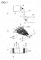
Fig. 1, (a) to (c) are diagrams which show a braided shield member and a wire harness according to one embodiment of the present invention, in whichFig. 1(a) is a schematic view which shows an arrangement example of the wire harness,Fig. 1(b) is a perspective view which shows a terminal part of the wire harness, andFig. 1(c) is an explanatory view of a composition of the wire harness. -
Fig. 2 is an enlarged perspective view which shows the terminal part of the braided shield member. - In
Fig. 3, (a) to (c) are diagrams which show how a loose state of an inside terminal part is formed, in whichFig. 3(a) is a diagram which shows a cut state,Fig. 3(b) is a diagram which shows a state that a bundle of metal wires are untied, andFig. 3(c) is a diagram which shows a state that the bundle of metal wires are further untied. - In
Fig. 4, (a) is an exploded perspective view which shows a conventional example of wire harnesses, and inFig. 4, (b) is a diagram which shows a braided shield member ofFig. 4(a) . -
Fig. 5 is a diagram which shows the details of the braided shield member ofFig. 4(a) . - A braided shield member which forms a wire harness according to one embodiment of the invention has a tubular body part and a terminal part. The braided shield member is formed so that the terminal part becomes a two-folded structure of an outside terminal part and an inside terminal part, and the inside terminal part is formed so that metal wires are in a loose state inside the stitches of the outside terminal part.
- Next, one embodiment is described with reference to the drawings.
Figs. 1(a) to 1(c) are diagrams which show a braided shield member and a wire harness according to the embodiment of the present invention.Fig. 2 is a diagram which shows a terminal part of the braided shield member, andFigs. 3(a) to 3(c) are diagrams which show how a loose state of an inside terminal part is formed. - The wire harness of this embodiment is not particularly limited, but may be arranged in a hybrid vehicle or an electric vehicle. In particular, the wire harness is a high voltage wire harness, and may be a wire harness that is arranged to connect a motor and an inverter, a wire harness that is arranged to connect an inverter and a battery, or a wire harness that is arranged to connect devices (for example, devices such as an electric junction box). Below, the wire harness which connects a motor and an inverter is described as an example.
- In
Figs. 1(a) to 1(c) , amotor 21 and aninverter 22 in an electric vehicle or a hybrid vehicle are electrically connected with a wire harness 23 (it is also called a motor cable). Thewire harness 23 includes aharness body 25 containing a plurality of high voltage electric wires 24 (conducting path), a motorside connecting part 26 provided at one end (terminal part) of theharness body 25, and an inverterside connecting part 27 provided at the other end (terminal part) of theharness body 25. Next, the components of thewire harness 23 are described. - The above-mentioned
harness body 25 includes a plurality of high voltageelectric wires 24, and aprotective member 28 which collectively covers the plurality of high voltageelectric wires 24. The high voltageelectric wire 24 is an electric wire for high voltage (high voltage cable), and three high voltage electric wires are used in this embodiment. The three high voltageelectric wires 24 are the same, and used together. The high voltageelectric wire 24 includes a conductor part and a covering part which covers the conductor part. The conductor part is not particularly limited, but is formed of stranded conductors made of copper or aluminum. Alternatively, the conductor part may be formed of a rectangular conductor or a round conductor similarly made of copper or aluminum. The high voltageelectric wire 24 in this embodiment is formed of a non-shielded electric wire. Other than an electric wire, a bus bar may be mentioned as an example of the conducting path. - The
protective member 28 is a member which collectively covers the plurality of high voltage electric wires as mentioned above. Theprotective member 28 is formed so that an electric wire protecting function and an electromagnetic shielding function can be demonstrated, since the high voltageelectric wires 24 are non-shielded electric wires. - The composition of the
protective member 28 is described specifically. Theprotective member 28 includes abraided shield member 29 which has a function of a shielding member, anexterior member 30 which is provided outside thebraided shield member 29, and a tape winding 31 which prevents the loosening of theexterior member 30. - In
Figs. 1(a) to 2 , thebraided shield member 29 is formed of braided conductors in which very thin wires, which have conductivity, are braided in a tube shape. Inside thebraided shield member 29, a plurality of high voltageelectric wires 24 are collectively inserted. Thebraided shield member 29 is not limited to the above, but may be formed in a tubular shape by winding a sheet. - The
braided shield member 29 is used by cutting the tubular braided conductors into a prescribed length, and has abody part 32 and aterminal part 33 which is continuous from thebody part 32. Thebraided shield member 29 is formed so that the inner diameter of theterminal part 33 is expanded to be larger than the inner diameter of thebody part 32. Thebraided shield member 29 is formed so that theend 34 of theterminal part 33 is bent inwards in the axial direction to become a two-folded structure. That is, theterminal part 33 is formed in the two-folded structure which contains anoutside terminal part 35 and an insideterminal part 36. - The
braided shield member 29 is formed in the two-folded structure when thebraided shield member 29 is cut, with theend 34 of theterminal part 33 unprocessed. After thebraided shield member 29 is cut as above, the insideterminal part 36 including theend 34 is formed in a loose state in which metal wires are loosed. InFig. 2 , the insideterminal part 36 is schematically illustrated with a shading. In a circle ofFig. 2 , the insideterminal part 36 is illustrated so that a loose state may be known. - Here, the above-mentioned loose state is described in more detail. The loose state indicates a state that the
metal wires 38 inside astitch 37 of the outsideterminal part 35 are crossed, as opposed to thestitch 37 of the outsideterminal part 35, as shown in the circle ofFig. 2 . When thepicks 39 each of which includes a plurality ofmetal wires 38 are seen as shown inFig. 3(a) , theend 34 which becomes a front end is cut (a cut state), and then, the loose state is formed by untying the bundle ofmetal wires 38 in each of thepicks 39 as shown fromFigs. 3(b) to 3(c) . The loose state is not particularly illustrated, but includes a "shaggy" form that themetal wires 38 may become. - In such a loose state, the
end 34 of theterminal part 33 is set to be arranged at a continuation position with thebody part 32, or to be arranged near the continuation position with the body part 32 (refer to the inside of the smaller circle inFig. 2 ). The arrangement of theend 34 is set in view of the shielding performance and is not limited to the above, but may be set at a middle position in the axial direction of theterminal part 33. - The end 34 (or inside terminal part 36) of the
terminal part 33 is not stopped with a tape or the like, that is, is in a tapeless or unfixed state. - A method of manufacturing the
braided shield member 29 may be known from the above-mentioned description, but the method includes a first procedure of forming abody part 32 and aterminal part 33 by cutting tubular braided conductors into a predetermined length, and a second procedure in which the inner diameter of theterminal part 33 is expanded to be larger than the inner diameter of thebody part 32, and theterminal part 33 is formed in a two-folded structure of the outsideterminal part 35 and the insideterminal part 36 by bending theend 34 of theterminal part 33 inwards in the axial direction, wherein in the second procedure, a loose state forming procedure is performed in which the insideterminal part 36 including theend 34 in the cut state is formed in a loose state in which themetal wires 38 are loosed. - The motor
side connecting part 26 or the inverterside connecting part 27 are provided at the bent part in theterminal part 33, in other words, the connecting part of the outsideterminal part 35 and the insideterminal part 36 in the above-mentionedbraided shield member 29. The motorside connecting part 26 or the inverterside connecting part 27 are publicly known shielding shells in this embodiment, and are formed to be able to be bolted to the shielding casing of themotor 21 or theinverter 22. The shielding shell is provided with an inner shell and an outer shell, and is formed so that the above-mentioned bent part may be put between the inner shell and the outer shell. - In
Figs. 1(a) to 1(c) , theexterior member 30 is provided as a member which demonstrates a protecting function against the outside. Theexterior member 30 used in this embodiment is sheet-shaped, wear resistant, and flexible (as an example). Theexterior member 30 is adapted to be wound outside thebraided shield member 29. As an example of theexterior member 30, for example, a twist tube may be mentioned, and the tape winding 31 may be put at a predetermined position of theexterior member 30. The whole length of theexterior member 30 is slightly shorter than thebraided shield member 29, and, for this reason, thebraided shield member 29 is exposed. At the boundary part where thebraided shield member 29 is exposed, for example, an acetate tube (not shown) is formed by winding a tape which is made of acetate crosses. Providing theexterior member 30 may be optional. - As mentioned above, as described with reference to
Figs. 1 to 3(c) , thebraided shield member 29 which forms thewire harness 23 has thetubular body part 32 and theterminal part 33, and such abraided shield member 29 is formed so that theterminal part 33 becomes the two-folded structure of the outsideterminal part 35 and the insideterminal part 36. Thebraided shield member 29 is formed so that themetal wires 38 are in a loose state inside thestitches 37 of the outsideterminal part 35. Therefore, in thebraided shield member 29, the opening area of thestitches 37 in theterminal part 33 is reduced, and as a result, effects are achieved that the deterioration of shielding performance can be prevented and that shielding performance can be demonstrated sufficiently. - The braided shield member, the manufacturing method of the braided shield member and the wire harness according to the present invention are described in detail with reference to the specific embodiments, but the invention is not limited to the previously described embodiments, and it is apparent that various modifications can be made without changing the purpose of the invention.
The present application is based on the Japanese patent application (patent application No.2010-126527) filed on June 2, 2010 - According to the braided shield member, the manufacturing method of the braided shield member, and the wire harness of the invention, although the stitches of the outside terminal part in the terminal part are opened larger than the stitches of the body part, the loose state of the metal wires inside the stitches of the outside terminal part is formed, and as a result, since the opening area of the stitches in the terminal part is reduced, the deterioration of shielding performance is prevented.
-
- 21: motor
- 22: inverter
- 23: wire harness
- 24: high voltage electric wire (conducting path)
- 25: harness body
- 26: motor side connecting part
- 27: inverter side connecting part
- 28: protective member
- 29: braided shield member
- 30: exterior member
- 31: tape winding
- 32: body part
- 33: terminal part
- 34: terminal
- 35: outside terminal part
- 36: inside terminal part
- 37: stitch
- 38: metal wire
- 39: pick
Claims (6)
- A braided shield member, comprising:a tubular body part; anda tubular terminal part that is continuous from the body part, whereinan inner diameter of the terminal part is expanded to be larger than an inner diameter of the body part,the terminal part is formed in a two-folded structure of an outside terminal part and an inside terminal part by bending an end of the terminal part inwards in an axial direction of the braided shield member,the end of the terminal part is in a cut state where the end of the terminal part is unprocessed, andthe inside terminal part including the end in the cut state is formed in a loose state in which metal wires are loosed.
- The braided shield member according to claim 1, wherein
the loose state of the inside terminal part is formed so that the metal wires inside stitches of the outside terminal part are crossed, as opposed to the stitches of the outside terminal part. - The braided shield member according to claim 1 or claim 2, wherein
the end of the terminal part is arranged at a continuation position with the body part or arranged near the continuation position. - A manufacturing method of a braided shield member, the method comprising:a first procedure of cutting a tubular braided conductor into a predetermined length and forming a body part and a terminal part which is continuous from the body part; anda second procedure in which an inner diameter of the terminal part is expanded to be larger than an inner diameter of the body part, and the terminal part is formed in a two-folded structure of an outside terminal part and an inside terminal part by bending an end of the terminal part inwards in an axial direction of the braided shield member, whereinthe second procedure includes a loose state forming procedure in which the inside terminal part including the end in the cut state is formed in a loose state in which metal wires are loosed.
- The manufacturing method of the braided shield member according to claim 4, wherein
the loose state is formed by untying a bundle of the metal wires in each pick which forms the braided conductor. - A wire harness, comprising:the braided shield member according to any one of claims 1 to 3; anda plurality of conducting paths collectively covered with the braided shield member.
Applications Claiming Priority (2)
| Application Number | Priority Date | Filing Date | Title |
|---|---|---|---|
| JP2010126527A JP5350323B2 (en) | 2010-06-02 | 2010-06-02 | Braided shield member, method for manufacturing braided shield member, and wire harness |
| PCT/JP2011/062523 WO2011152416A1 (en) | 2010-06-02 | 2011-05-31 | Braided shield member, method of manufacturing braided shield member, and wire harness |
Publications (1)
| Publication Number | Publication Date |
|---|---|
| EP2579405A1 true EP2579405A1 (en) | 2013-04-10 |
Family
ID=45066778
Family Applications (1)
| Application Number | Title | Priority Date | Filing Date |
|---|---|---|---|
| EP11789819.7A Withdrawn EP2579405A1 (en) | 2010-06-02 | 2011-05-31 | Braided shield member, method of manufacturing braided shield member, and wire harness |
Country Status (5)
| Country | Link |
|---|---|
| US (1) | US8895875B2 (en) |
| EP (1) | EP2579405A1 (en) |
| JP (1) | JP5350323B2 (en) |
| CN (1) | CN102918730B (en) |
| WO (1) | WO2011152416A1 (en) |
Cited By (3)
| Publication number | Priority date | Publication date | Assignee | Title |
|---|---|---|---|---|
| DE102014217133A1 (en) * | 2014-08-28 | 2016-03-03 | Volkswagen Aktiengesellschaft | Shielding and high-voltage system |
| WO2016135229A1 (en) * | 2015-02-27 | 2016-09-01 | Leoni Bordnetz-Systeme Gmbh | High-voltage cable set |
| CN110238320A (en) * | 2019-06-18 | 2019-09-17 | 国网河北省电力有限公司沧州供电分公司 | A kind of dedicated cable buncher of secondary line |
Families Citing this family (29)
| Publication number | Priority date | Publication date | Assignee | Title |
|---|---|---|---|---|
| US9040845B2 (en) * | 2010-12-27 | 2015-05-26 | Yazaki Corporation | Shielding structure for wire harness |
| US9318849B2 (en) * | 2011-04-14 | 2016-04-19 | Yazaki Corporation | Shielded connector |
| US20140308847A1 (en) * | 2011-11-24 | 2014-10-16 | Yazaki Corporation | Braid fixture |
| FR2990803B1 (en) * | 2012-05-16 | 2015-04-10 | Nicomatic | SHIELDED ELECTRIC CABLES CONNECTOR AND CORRESPONDING ASSEMBLY METHOD |
| JP5772718B2 (en) * | 2012-05-22 | 2015-09-02 | 日立金属株式会社 | Connection structure between shield shell and braided shield and wire harness |
| JP5915515B2 (en) * | 2012-12-25 | 2016-05-11 | 日立金属株式会社 | Connection structure between wire harness and shield shell and braided shield |
| JP5920209B2 (en) | 2012-12-28 | 2016-05-18 | 日立金属株式会社 | Wire harness |
| JP5987686B2 (en) * | 2012-12-28 | 2016-09-07 | 日立金属株式会社 | Wire harness |
| JP6169371B2 (en) * | 2013-02-28 | 2017-07-26 | 矢崎総業株式会社 | Shield member and manufacturing method thereof |
| JP6062812B2 (en) * | 2013-06-17 | 2017-01-18 | 矢崎総業株式会社 | Shield unit |
| JP2015018756A (en) * | 2013-07-12 | 2015-01-29 | 住友電装株式会社 | Braided conductor |
| JP6224945B2 (en) * | 2013-08-01 | 2017-11-01 | 矢崎総業株式会社 | Wire harness |
| CN103414061A (en) * | 2013-08-17 | 2013-11-27 | 深圳市得润电子股份有限公司 | VGA connecting wire of parallel wire structure and manufacturing method thereof |
| CN105765811B (en) * | 2013-11-12 | 2018-11-06 | 住友电装株式会社 | Shielding conductor |
| JP6191489B2 (en) * | 2014-02-06 | 2017-09-06 | 株式会社オートネットワーク技術研究所 | Electromagnetic shield parts and electric wires with electromagnetic shield parts |
| JP6582649B2 (en) * | 2015-07-10 | 2019-10-02 | 株式会社オートネットワーク技術研究所 | Shield structure |
| JP6376078B2 (en) * | 2015-08-24 | 2018-08-22 | 株式会社オートネットワーク技術研究所 | Tubular conductive braid and wiring module with electromagnetic shield |
| US9947435B2 (en) * | 2016-03-10 | 2018-04-17 | Hitachi Metals, Ltd. | Wire harness |
| US10023136B2 (en) | 2016-03-10 | 2018-07-17 | Hitachi Metals, Ltd. | Wire harness |
| JP6356729B2 (en) * | 2016-06-03 | 2018-07-11 | 矢崎総業株式会社 | Wire harness |
| JP6700613B2 (en) * | 2017-03-22 | 2020-05-27 | 株式会社オートネットワーク技術研究所 | Conductive wire |
| DE112018003214T5 (en) | 2017-06-21 | 2020-03-19 | Acs Industries, Inc. | Tubular all-wire weft knitting sleeve with improved electrical continuity |
| JP6913070B2 (en) * | 2018-11-20 | 2021-08-04 | 矢崎総業株式会社 | Shield connector |
| FR3098339B1 (en) | 2019-07-02 | 2021-07-23 | Delfingen Fr Anteuil | Electromagnetic shielding device |
| US11825640B2 (en) | 2019-07-02 | 2023-11-21 | Delfingen Industry | Electromagnetic shielding device |
| US10966357B2 (en) | 2019-07-02 | 2021-03-30 | Delfingen Fr-Anteuil | Electromagnetic shielding device |
| CN114009159A (en) | 2019-07-02 | 2022-02-01 | 德尔菲让法国-安特尤勒有限公司 | Electromagnetic shielding device |
| JP7581890B2 (en) * | 2021-01-13 | 2024-11-13 | 株式会社オートネットワーク技術研究所 | Wire Harness |
| EP4325667B1 (en) * | 2022-08-17 | 2025-04-30 | Volvo Car Corporation | Grounding device for a vehicle |
Family Cites Families (10)
| Publication number | Priority date | Publication date | Assignee | Title |
|---|---|---|---|---|
| US5401177A (en) * | 1993-06-01 | 1995-03-28 | Raychem Corporation | Mass termination connector backshell |
| US6887105B2 (en) * | 2001-06-14 | 2005-05-03 | Ncr Corporation | Providing shields to reduce electromagnetic interference from connectors |
| JP2003264040A (en) * | 2002-03-08 | 2003-09-19 | Auto Network Gijutsu Kenkyusho:Kk | Shielded wire |
| JP3909763B2 (en) * | 2002-11-20 | 2007-04-25 | 株式会社オートネットワーク技術研究所 | Vehicle conductive path with shield function |
| JP3947096B2 (en) * | 2002-11-26 | 2007-07-18 | 株式会社オートネットワーク技術研究所 | Conductive path and shield member with shield function |
| JP2005012925A (en) * | 2003-06-19 | 2005-01-13 | Sumitomo Electric Ind Ltd | Phase branching structure of multiphase superconducting cable |
| JP2005339933A (en) | 2004-05-26 | 2005-12-08 | Yazaki Corp | Shielded wire fixing structure |
| JP5331310B2 (en) | 2007-04-11 | 2013-10-30 | 矢崎エナジーシステム株式会社 | Electromagnetic shielding cable |
| JP2009129697A (en) * | 2007-11-22 | 2009-06-11 | Honda Motor Co Ltd | Electromagnetic wave shield structure of distribution cable |
| WO2011076819A2 (en) * | 2009-12-24 | 2011-06-30 | Fci | Cable junction |
-
2010
- 2010-06-02 JP JP2010126527A patent/JP5350323B2/en not_active Expired - Fee Related
-
2011
- 2011-05-31 CN CN201180027422.2A patent/CN102918730B/en not_active Expired - Fee Related
- 2011-05-31 EP EP11789819.7A patent/EP2579405A1/en not_active Withdrawn
- 2011-05-31 WO PCT/JP2011/062523 patent/WO2011152416A1/en not_active Ceased
- 2011-05-31 US US13/700,763 patent/US8895875B2/en not_active Expired - Fee Related
Non-Patent Citations (1)
| Title |
|---|
| See references of WO2011152416A1 * |
Cited By (5)
| Publication number | Priority date | Publication date | Assignee | Title |
|---|---|---|---|---|
| DE102014217133A1 (en) * | 2014-08-28 | 2016-03-03 | Volkswagen Aktiengesellschaft | Shielding and high-voltage system |
| DE102014217133B4 (en) | 2014-08-28 | 2024-01-11 | Volkswagen Aktiengesellschaft | Shielding and high-voltage system |
| WO2016135229A1 (en) * | 2015-02-27 | 2016-09-01 | Leoni Bordnetz-Systeme Gmbh | High-voltage cable set |
| CN110238320A (en) * | 2019-06-18 | 2019-09-17 | 国网河北省电力有限公司沧州供电分公司 | A kind of dedicated cable buncher of secondary line |
| CN110238320B (en) * | 2019-06-18 | 2020-06-23 | 国网河北省电力有限公司沧州供电分公司 | A special wire harness for secondary wires |
Also Published As
| Publication number | Publication date |
|---|---|
| WO2011152416A1 (en) | 2011-12-08 |
| JP5350323B2 (en) | 2013-11-27 |
| US8895875B2 (en) | 2014-11-25 |
| CN102918730B (en) | 2015-10-07 |
| US20130068518A1 (en) | 2013-03-21 |
| CN102918730A (en) | 2013-02-06 |
| JP2011254613A (en) | 2011-12-15 |
Similar Documents
| Publication | Publication Date | Title |
|---|---|---|
| US8895875B2 (en) | Braided shield member, manufacturing method of braided shield member, and wire harness | |
| US9676349B2 (en) | Shield conductive path | |
| EP2533253B1 (en) | Wire harness | |
| EP2841308B1 (en) | Wire harness | |
| US9346420B2 (en) | Wire harness | |
| US9742168B2 (en) | Conductive path | |
| US20110094796A1 (en) | Wire harness | |
| US9819164B2 (en) | Wire harness intermediate member, and wire harness | |
| US20130126232A1 (en) | Wire harness waterproof structure | |
| US9522640B2 (en) | Wire harness and shield conductive path | |
| EP2766910B1 (en) | Braid and wire harness | |
| JP2006156051A (en) | High voltage wire harness | |
| EP2597653A1 (en) | Wire harness | |
| JP2021106210A (en) | Wire harness | |
| EP2809551B1 (en) | Protector and wire harness | |
| JP2023023540A (en) | Wire harness and production method therefor | |
| JP2018063764A (en) | Conducting path | |
| JP2017004862A (en) | Wire harness and electric wire-holding member | |
| JP2019179895A (en) | Wire harness | |
| JP2012138187A (en) | Shield wire and method of manufacturing the same | |
| JP2007207738A (en) | Shielded wire harness and method for manufacturing shielded wire harness | |
| JP7575303B2 (en) | Wire harness and ground structure | |
| JP2022136632A (en) | Wire Harness |
Legal Events
| Date | Code | Title | Description |
|---|---|---|---|
| PUAI | Public reference made under article 153(3) epc to a published international application that has entered the european phase |
Free format text: ORIGINAL CODE: 0009012 |
|
| 17P | Request for examination filed |
Effective date: 20121203 |
|
| AK | Designated contracting states |
Kind code of ref document: A1 Designated state(s): AL AT BE BG CH CY CZ DE DK EE ES FI FR GB GR HR HU IE IS IT LI LT LU LV MC MK MT NL NO PL PT RO RS SE SI SK SM TR |
|
| DAX | Request for extension of the european patent (deleted) | ||
| STAA | Information on the status of an ep patent application or granted ep patent |
Free format text: STATUS: THE APPLICATION HAS BEEN WITHDRAWN |
|
| 18W | Application withdrawn |
Effective date: 20160531 |