EP2578945A2 - Forward casing with a circumferential sloped surface and a combustor assembly including same - Google Patents
Forward casing with a circumferential sloped surface and a combustor assembly including same Download PDFInfo
- Publication number
- EP2578945A2 EP2578945A2 EP12186711.3A EP12186711A EP2578945A2 EP 2578945 A2 EP2578945 A2 EP 2578945A2 EP 12186711 A EP12186711 A EP 12186711A EP 2578945 A2 EP2578945 A2 EP 2578945A2
- Authority
- EP
- European Patent Office
- Prior art keywords
- circumferential
- forward casing
- sloped surface
- casing
- cylindrical body
- Prior art date
- Legal status (The legal status is an assumption and is not a legal conclusion. Google has not performed a legal analysis and makes no representation as to the accuracy of the status listed.)
- Withdrawn
Links
Images



Classifications
-
- F—MECHANICAL ENGINEERING; LIGHTING; HEATING; WEAPONS; BLASTING
- F23—COMBUSTION APPARATUS; COMBUSTION PROCESSES
- F23R—GENERATING COMBUSTION PRODUCTS OF HIGH PRESSURE OR HIGH VELOCITY, e.g. GAS-TURBINE COMBUSTION CHAMBERS
- F23R3/00—Continuous combustion chambers using liquid or gaseous fuel
- F23R3/42—Continuous combustion chambers using liquid or gaseous fuel characterised by the arrangement or form of the flame tubes or combustion chambers
- F23R3/46—Combustion chambers comprising an annular arrangement of several essentially tubular flame tubes within a common annular casing or within individual casings
-
- F—MECHANICAL ENGINEERING; LIGHTING; HEATING; WEAPONS; BLASTING
- F23—COMBUSTION APPARATUS; COMBUSTION PROCESSES
- F23R—GENERATING COMBUSTION PRODUCTS OF HIGH PRESSURE OR HIGH VELOCITY, e.g. GAS-TURBINE COMBUSTION CHAMBERS
- F23R3/00—Continuous combustion chambers using liquid or gaseous fuel
- F23R3/02—Continuous combustion chambers using liquid or gaseous fuel characterised by the air-flow or gas-flow configuration
- F23R3/04—Air inlet arrangements
- F23R3/10—Air inlet arrangements for primary air
-
- F—MECHANICAL ENGINEERING; LIGHTING; HEATING; WEAPONS; BLASTING
- F23—COMBUSTION APPARATUS; COMBUSTION PROCESSES
- F23R—GENERATING COMBUSTION PRODUCTS OF HIGH PRESSURE OR HIGH VELOCITY, e.g. GAS-TURBINE COMBUSTION CHAMBERS
- F23R3/00—Continuous combustion chambers using liquid or gaseous fuel
- F23R3/28—Continuous combustion chambers using liquid or gaseous fuel characterised by the fuel supply
- F23R3/286—Continuous combustion chambers using liquid or gaseous fuel characterised by the fuel supply having fuel-air premixing devices
-
- F—MECHANICAL ENGINEERING; LIGHTING; HEATING; WEAPONS; BLASTING
- F23—COMBUSTION APPARATUS; COMBUSTION PROCESSES
- F23R—GENERATING COMBUSTION PRODUCTS OF HIGH PRESSURE OR HIGH VELOCITY, e.g. GAS-TURBINE COMBUSTION CHAMBERS
- F23R2900/00—Special features of, or arrangements for continuous combustion chambers; Combustion processes therefor
- F23R2900/00014—Reducing thermo-acoustic vibrations by passive means, e.g. by Helmholtz resonators
Definitions
- a combustor assembly for a turbine engine mixes compressed air with fuel, and the air-fuel mixture is then ignited to generate expanding combustion gases that drive the turbine.
- a partial cross-sectional view of a combustor assembly is illustrated in Fig. 1 .
- the combustor assembly includes an aft casing 130 having a combustor liner 110 mounted therein.
- a flow sleeve 120 is also mounted inside the aft casing 130.
- a forward casing 160 is attached to the forward end of the aft casing 130.
- An aft flange 167 on the forward casing 160 is used to attach the forward casing 160 to the aft casing 130.
- An end cover 170 is then attached to the forward end of the forward casing 160 via a forward flange 165.
- a cap assembly 140 is mounted on the aft side of the forward casing 160.
- a plurality of cylindrical mounting elements 142 in the cap assembly 140 receive corresponding fuel nozzles 150 that deliver fuel into a flow of compressed air.
- compressed air is introduced into the combustor assembly through an annular space formed between the combustor liner 110 and the flow sleeve 120. This annular space extends past the end cap 140 and into an interior of the forward casing 160. As also illustrated by the arrows in Fig. 1 , the compressed air introduced into the forward casing 160 then turns 180 degrees so that it can flow pass the fuel nozzles 150 where fuel is delivered into the flow of compressed air. The fuel-air mixture is then delivered into the interior 106 of the combustor liner 110, where it is ignited to create expanding gases which are used to drive the turbine.
- a circumferential fuel supply passageway 162 is provided around the exterior of the forward casing 160.
- a plurality of radially extending fuel nozzles 164 extend inward from the inner wall of the forward casing 160.
- the fuel nozzles 164 are operatively coupled to the circumferential fuel passageway 162 so that the fuel in the circumferential fuel passageway 162 can be delivered into the compressed air flowing past the radially-extending fuel nozzles 164.
- the geometry of the interior volume of the forward casing 160 can cause resonant vibrations to occur within the compressed air.
- the resonant vibrations which are also referred to as "dynamics" are undesirable, and can harm the components of the combustor assembly, as well as lower the overall efficiency of the turbine engine.
- One way to reduce or eliminate resonant vibrations generated in the forward casing is to reduce the interior within the forward casing 160.
- Fig. 2 illustrates another combustor assembly similar to the one described above in connection with Fig. 1 .
- an insert 180 has been mounted inside the forward casing 160.
- a plurality of fasteners 183 are used to attach the insert 180 to the interior circumferential surface of the forward casing 160.
- the insert 180 includes a sloped or conical surface 182 which serves to reduce the interior volume within the forward casing. As noted above, this reduction in the interior volume of the forward casing 160 can help to reduce or eliminate undesirable resonant vibrations.
- the insert 180 is attached to the forward casing 160 with fasteners 183, there is a possibility that one or more of the fasteners 183 may loosen or break off during operation of the turbine engine. If this were to occur, there is a possibility that a fastener 183 would be swept through the combustor liner 110 and into the turbine section of the turbine engine. Once in the turbine section, the fastener 183 would impact the rotating turbine blades and the stationary stator blades, which is likely to cause extensive damage to the turbine engine, requiring immediate shutdown and repair.
- the present invention resides in an integral forward casing for a combustor assembly of a turbine engine, comprising a generally cylindrical body; an aft mounting flange located at a first end of the generally cylindrical body and that is configured to be attached to an aft casing of a combustor assembly; a forward mounting flange located at a second end of the generally cylindrical body and that is configured to be attached to an end cover of a combustor assembly; and a circumferential sloped surface that is integrally formed on an inner side of the generally cylindrical body, wherein a diameter of an end of the circumferential sloped surface located closest to the second end of the generally cylindrical body is smaller than a diameter of an end of the circumferential sloped surface located closest to the first end of the generally cylindrical body.
- the present invention resides in a combustor assembly for a turbine engine, comprising an end cover; an aft casing having a combustor liner mounted therein; a cap assembly mounted between the forward casing and the end cover; at least one fuel nozzle mounted on the cap assembly and an integral forward casing mounted between the aft casing and the end cover, wherein the forward casing includes a circumferential sloped surface that that slopes inward from the aft casing side to the end cover side of the forward casing.
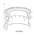
- Fig. 3 illustrates a new forward casing for a combustor assembly of a turbine engine.
- the forward casing 300 includes a generally-cylindrical body with an aft mounting flange 367 formed at a first end of the cylindrical body.
- the aft mounting flange 367 is used to attach the forward casing 300 to an aft casing of a combustor assembly.
- a forward mounting flange 365 located on a second end of the generally-cylindrical body is used to attach the forward casing 300 to an end cover of a combustor assembly.
- the forward casing 300 also includes a circumferential fuel passageway 362 which feeds fuel to a plurality of inward, radially-extending fuel nozzles 364.
- the forward casing illustrated in Fig. 3 also includes a circumferential sloped surface 368 which slopes inward towards the forward side of the cylindrical body.
- a radially-extending end portion 366 then extends from the smallest diameter portion of the circumferential sloped surface 368 back to the forward mounting flange 365.
- a forward casing having a circumferential sloped surface as illustrated in Fig. 3 provides the benefits of the removable insert 180 illustrated in Fig. 2 .
- the circumferential sloped surface 368 reduces the total interior volume of the forward casing to help reduce or eliminate undesirable resonant vibrations which can otherwise occur.
- the circumferential sloped surface 368 is an integral part of the forward casing 300, there's no possibility of a fastener coming loose and causing damage to the turbine engine.
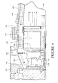
- Fig. 4 shows a partial cross-sectional view of a portion of a combustor assembly having an integral forward casing as illustrated in Fig. 3 .
- compressed air entering the forward casing will be deflected by the circumferential sloped surface 368 of the integral forward casing 300 to help turn the flow of compressed air so that it can reverse direction.
- the circumferential sloped surface 368 serves to reduce the interior volume within the forward casing.
- Fig. 5 shows another cross-sectional view of a portion of a combustor assembly which includes an integral forward casing with a circumferential sloped surface 568.
- the circumferential sloped surface 568 has a concave shape.
- the concave shape of the circumferential sloped surface 568 may better assist in turning the flow of compressed air so that it can reverse direction within the forward casing.
Landscapes
- Engineering & Computer Science (AREA)
- Chemical & Material Sciences (AREA)
- Combustion & Propulsion (AREA)
- Mechanical Engineering (AREA)
- General Engineering & Computer Science (AREA)
- Turbine Rotor Nozzle Sealing (AREA)
- Pre-Mixing And Non-Premixing Gas Burner (AREA)
Abstract
A forward casing (300) used in a combustor assembly for a turbine engine includes a circumferential sloped surface (368) which reduces the total interior volume within the forward casing (300). The circumferential sloped surface (368) can be flat or concave shaped.
Description
- A combustor assembly for a turbine engine mixes compressed air with fuel, and the air-fuel mixture is then ignited to generate expanding combustion gases that drive the turbine. A partial cross-sectional view of a combustor assembly is illustrated in
Fig. 1 . - As shown in
Fig. 1 , the combustor assembly includes anaft casing 130 having acombustor liner 110 mounted therein. Aflow sleeve 120 is also mounted inside theaft casing 130. - A
forward casing 160 is attached to the forward end of theaft casing 130. Anaft flange 167 on theforward casing 160 is used to attach theforward casing 160 to theaft casing 130. Anend cover 170 is then attached to the forward end of theforward casing 160 via aforward flange 165. - A
cap assembly 140 is mounted on the aft side of theforward casing 160. A plurality ofcylindrical mounting elements 142 in thecap assembly 140 receivecorresponding fuel nozzles 150 that deliver fuel into a flow of compressed air. - As illustrated by the arrows appearing in
Fig. 1 , compressed air is introduced into the combustor assembly through an annular space formed between thecombustor liner 110 and theflow sleeve 120. This annular space extends past theend cap 140 and into an interior of theforward casing 160. As also illustrated by the arrows inFig. 1 , the compressed air introduced into theforward casing 160 then turns 180 degrees so that it can flow pass thefuel nozzles 150 where fuel is delivered into the flow of compressed air. The fuel-air mixture is then delivered into theinterior 106 of thecombustor liner 110, where it is ignited to create expanding gases which are used to drive the turbine. - As also illustrated in
Fig. 1 , a circumferentialfuel supply passageway 162 is provided around the exterior of theforward casing 160. A plurality of radially extendingfuel nozzles 164 extend inward from the inner wall of theforward casing 160. Thefuel nozzles 164 are operatively coupled to thecircumferential fuel passageway 162 so that the fuel in thecircumferential fuel passageway 162 can be delivered into the compressed air flowing past the radially-extendingfuel nozzles 164. - The geometry of the interior volume of the
forward casing 160 can cause resonant vibrations to occur within the compressed air. The resonant vibrations, which are also referred to as "dynamics" are undesirable, and can harm the components of the combustor assembly, as well as lower the overall efficiency of the turbine engine. One way to reduce or eliminate resonant vibrations generated in the forward casing is to reduce the interior within theforward casing 160. -
Fig. 2 illustrates another combustor assembly similar to the one described above in connection withFig. 1 . However, in the embodiment illustrated inFig. 2 aninsert 180 has been mounted inside theforward casing 160. A plurality offasteners 183 are used to attach theinsert 180 to the interior circumferential surface of theforward casing 160. Theinsert 180 includes a sloped orconical surface 182 which serves to reduce the interior volume within the forward casing. As noted above, this reduction in the interior volume of theforward casing 160 can help to reduce or eliminate undesirable resonant vibrations. - Because the
insert 180 is attached to theforward casing 160 withfasteners 183, there is a possibility that one or more of thefasteners 183 may loosen or break off during operation of the turbine engine. If this were to occur, there is a possibility that afastener 183 would be swept through thecombustor liner 110 and into the turbine section of the turbine engine. Once in the turbine section, thefastener 183 would impact the rotating turbine blades and the stationary stator blades, which is likely to cause extensive damage to the turbine engine, requiring immediate shutdown and repair. - While there may only be a small likelihood that one of the
fasteners 183 used to attach theinsert 180 to theforward casing 160 might come loose, the amount of damage which could occur if this happens is extensive and very expensive. It would also result in the shutdown of a turbine engine, which could severely impact a power plant's ability to produce sufficient electrical power. - The present invention resides in an integral forward casing for a combustor assembly of a turbine engine, comprising a generally cylindrical body; an aft mounting flange located at a first end of the generally cylindrical body and that is configured to be attached to an aft casing of a combustor assembly; a forward mounting flange located at a second end of the generally cylindrical body and that is configured to be attached to an end cover of a combustor assembly; and a circumferential sloped surface that is integrally formed on an inner side of the generally cylindrical body, wherein a diameter of an end of the circumferential sloped surface located closest to the second end of the generally cylindrical body is smaller than a diameter of an end of the circumferential sloped surface located closest to the first end of the generally cylindrical body.
- The present invention resides in a combustor assembly for a turbine engine, comprising an end cover; an aft casing having a combustor liner mounted therein; a cap assembly mounted between the forward casing and the end cover; at least one fuel nozzle mounted on the cap assembly and an integral forward casing mounted between the aft casing and the end cover, wherein the forward casing includes a circumferential sloped surface that that slopes inward from the aft casing side to the end cover side of the forward casing.
- Embodiments of the present invention will now be described, by way of example only, with reference to the accompanying drawings in which:
-
Figure 1 is a cross-sectional view of a portion of a combustor assembly of a turbine engine; -
Figure 2 is a cross-sectional view of a portion of a combustor assembly of a turbine engine which includes a removable insert mounted in the forward casing; -
Figure 3 is a partial perspective view of an integral forward casing which includes a sloped-circumferential surface; -
Figure 4 is partial cross-sectional view of a combustor assembly of a turbine engine which includes the integral forward casing illustrated inFig. 3 ; and -
Figure 5 is a partial cross-sectional view of a portion of a combustor assembly of a turbine engine which includes an integral forward casing as illustrated inFig. 3 with a concave circumferential sloped surface. - For all the reasons explained above in the Background Section, attaching a removable insert to the interior of a forward casing of a combustor assembly is potentially dangerous, in that the fasteners used for this purpose can come loose and be sucked into the turbine section of the turbine engine. For these reasons, the benefits obtained through the use of an insert may be outweighed by the potential damage that can occur.
-
Fig. 3 illustrates a new forward casing for a combustor assembly of a turbine engine. Theforward casing 300 includes a generally-cylindrical body with anaft mounting flange 367 formed at a first end of the cylindrical body. Theaft mounting flange 367 is used to attach theforward casing 300 to an aft casing of a combustor assembly. In addition, aforward mounting flange 365 located on a second end of the generally-cylindrical body is used to attach theforward casing 300 to an end cover of a combustor assembly. Theforward casing 300 also includes acircumferential fuel passageway 362 which feeds fuel to a plurality of inward, radially-extendingfuel nozzles 364. - The forward casing illustrated in
Fig. 3 also includes a circumferential slopedsurface 368 which slopes inward towards the forward side of the cylindrical body. A radially-extendingend portion 366 then extends from the smallest diameter portion of the circumferential slopedsurface 368 back to theforward mounting flange 365. - A forward casing having a circumferential sloped surface as illustrated in
Fig. 3 provides the benefits of theremovable insert 180 illustrated inFig. 2 . Specifically, the circumferential slopedsurface 368 reduces the total interior volume of the forward casing to help reduce or eliminate undesirable resonant vibrations which can otherwise occur. However, because the circumferential slopedsurface 368 is an integral part of theforward casing 300, there's no possibility of a fastener coming loose and causing damage to the turbine engine. -
Fig. 4 shows a partial cross-sectional view of a portion of a combustor assembly having an integral forward casing as illustrated inFig. 3 . As shown by the arrows inFig. 4 , compressed air entering the forward casing will be deflected by the circumferential slopedsurface 368 of the integralforward casing 300 to help turn the flow of compressed air so that it can reverse direction. In addition, as illustrated inFig. 4 , the circumferential slopedsurface 368 serves to reduce the interior volume within the forward casing. -
Fig. 5 shows another cross-sectional view of a portion of a combustor assembly which includes an integral forward casing with a circumferential slopedsurface 568. In this embodiment, the circumferential slopedsurface 568 has a concave shape. The concave shape of the circumferential slopedsurface 568 may better assist in turning the flow of compressed air so that it can reverse direction within the forward casing. - While the invention has been described in connection with what is presently considered to be the most practical and preferred embodiment, it is to be understood that the invention is not to be limited to the disclosed embodiment, but on the contrary, is intended to cover various modifications and equivalent arrangements included within the spirit and scope of the appended claims.
Claims (9)
- An integral forward casing (300) for a combustor assembly of a turbine engine, comprising:a generally cylindrical body;an aft mounting flange (367) located at a first end of the generally cylindrical body and that is configured to be attached to an aft casing (130) of a combustor assembly;a forward mounting flange (365) located at a second end of the generally cylindrical body and that is configured to be attached to an end cover (170) of a combustor assembly; anda circumferential sloped surface (368) that is integrally formed on an inner side of the generally cylindrical body, wherein a diameter of an end of the circumferential sloped surface (368) located closest to the second end of the generally cylindrical body is smaller than a diameter of an end of the circumferential sloped surface (368) located closest to the first end of the generally cylindrical body.
- The integral forward casing of claim 1, wherein the integral forward casing (30) includes a circumferential fuel passageway (362) that extends around an outer side of the generally cylindrical body.
- The integral forward casing of claim 2, further comprising a plurality of fuel nozzles (364) that extend radially inward from an inner wall of the generally cylindrical body and that are operatively coupled to the circumferential fuel passageway (362) such that fuel in the circumferential fuel passageway (362) is fed into the plurality of fuel nozzles (364).
- The integral forward casing of claim 2, wherein the circumferential sloped surface (368) is located closer to the second end of the generally cylindrical body than the plurality of fuel nozzles (364).
- The integral forward casing of any of claims 1 to 4, wherein the circumferential sloped surface (368) is flat, such that the circumferential sloped surface (368) is generally conical.
- The integral forward casing of any of claims 1 to 4, wherein the circumferential sloped surface (368) is concave shaped.
- The integral forward casing (300) of any preceding claim, wherein the generally cylindrical body and the circumferential sloped surface (368) are formed as a single integral part.
- A combustor assembly for a turbine engine, comprising:an end cover (170);an aft casing (130) having a combustor liner (110) mounted therein;a cap assembly (140) mounted between a forward casing (300) and the end cover (170);at least one fuel nozzle (150) mounted on the cap assembly (140); andthe integral forward casing of any of claims 1 to 7.
- The combustor assembly of claim 8, wherein the circumferential sloped surface (368) of the integral forward casing is located on the end cover (170) side of the plurality of fuel nozzles.
Applications Claiming Priority (1)
| Application Number | Priority Date | Filing Date | Title |
|---|---|---|---|
| US13/252,525 US20130081397A1 (en) | 2011-10-04 | 2011-10-04 | Forward casing with a circumferential sloped surface and a combustor assembly including same |
Publications (1)
| Publication Number | Publication Date |
|---|---|
| EP2578945A2 true EP2578945A2 (en) | 2013-04-10 |
Family
ID=47046376
Family Applications (1)
| Application Number | Title | Priority Date | Filing Date |
|---|---|---|---|
| EP12186711.3A Withdrawn EP2578945A2 (en) | 2011-10-04 | 2012-09-28 | Forward casing with a circumferential sloped surface and a combustor assembly including same |
Country Status (3)
| Country | Link |
|---|---|
| US (1) | US20130081397A1 (en) |
| EP (1) | EP2578945A2 (en) |
| CN (1) | CN103032901A (en) |
Families Citing this family (1)
| Publication number | Priority date | Publication date | Assignee | Title |
|---|---|---|---|---|
| US9400108B2 (en) * | 2013-05-14 | 2016-07-26 | Siemens Aktiengesellschaft | Acoustic damping system for a combustor of a gas turbine engine |
Family Cites Families (26)
| Publication number | Priority date | Publication date | Assignee | Title |
|---|---|---|---|---|
| US3768250A (en) * | 1971-12-01 | 1973-10-30 | Mitsubishi Heavy Ind Ltd | Combustion apparatus for a gas turbine |
| US4483149A (en) * | 1982-05-20 | 1984-11-20 | United Technologies Corporation | Diffuser case for a gas turbine engine |
| US4928481A (en) * | 1988-07-13 | 1990-05-29 | Prutech Ii | Staged low NOx premix gas turbine combustor |
| CN2173906Y (en) * | 1993-09-19 | 1994-08-10 | 汤民生 | Inclined spiral-flow burner |
| GB2284884B (en) * | 1993-12-16 | 1997-12-10 | Rolls Royce Plc | A gas turbine engine combustion chamber |
| AU681271B2 (en) * | 1994-06-07 | 1997-08-21 | Westinghouse Electric Corporation | Method and apparatus for sequentially staged combustion using a catalyst |
| US5596873A (en) * | 1994-09-14 | 1997-01-28 | General Electric Company | Gas turbine combustor with a plurality of circumferentially spaced pre-mixers |
| GB9818160D0 (en) * | 1998-08-21 | 1998-10-14 | Rolls Royce Plc | A combustion chamber |
| JP3364169B2 (en) * | 1999-06-09 | 2003-01-08 | 三菱重工業株式会社 | Gas turbine and its combustor |
| GB9915770D0 (en) * | 1999-07-07 | 1999-09-08 | Rolls Royce Plc | A combustion chamber |
| JP3962554B2 (en) * | 2001-04-19 | 2007-08-22 | 三菱重工業株式会社 | Gas turbine combustor and gas turbine |
| US6813889B2 (en) * | 2001-08-29 | 2004-11-09 | Hitachi, Ltd. | Gas turbine combustor and operating method thereof |
| US6840048B2 (en) * | 2002-09-26 | 2005-01-11 | General Electric Company | Dynamically uncoupled can combustor |
| GB2396687A (en) * | 2002-12-23 | 2004-06-30 | Rolls Royce Plc | Helmholtz resonator for combustion chamber use |
| US7152411B2 (en) * | 2003-06-27 | 2006-12-26 | General Electric Company | Rabbet mounted combuster |
| US7093441B2 (en) * | 2003-10-09 | 2006-08-22 | United Technologies Corporation | Gas turbine annular combustor having a first converging volume and a second converging volume, converging less gradually than the first converging volume |
| US7421843B2 (en) * | 2005-01-15 | 2008-09-09 | Siemens Power Generation, Inc. | Catalytic combustor having fuel flow control responsive to measured combustion parameters |
| JP2006220350A (en) * | 2005-02-10 | 2006-08-24 | Hitachi Ltd | Gas turbine equipment and operation method thereof |
| US20060230763A1 (en) * | 2005-04-13 | 2006-10-19 | General Electric Company | Combustor and cap assemblies for combustors in a gas turbine |
| WO2007033306A2 (en) * | 2005-09-13 | 2007-03-22 | Rolls-Royce Corporation, Ltd. | Gas turbine engine combustion systems |
| US7954325B2 (en) * | 2005-12-06 | 2011-06-07 | United Technologies Corporation | Gas turbine combustor |
| US8141370B2 (en) * | 2006-08-08 | 2012-03-27 | General Electric Company | Methods and apparatus for radially compliant component mounting |
| US9062563B2 (en) * | 2008-04-09 | 2015-06-23 | General Electric Company | Surface treatments for preventing hydrocarbon thermal degradation deposits on articles |
| RU2534189C2 (en) * | 2010-02-16 | 2014-11-27 | Дженерал Электрик Компани | Gas turbine combustion chamber (versions) and method of its operation |
| US8991187B2 (en) * | 2010-10-11 | 2015-03-31 | General Electric Company | Combustor with a lean pre-nozzle fuel injection system |
| US9447970B2 (en) * | 2011-05-12 | 2016-09-20 | General Electric Company | Combustor casing for combustion dynamics mitigation |
-
2011
- 2011-10-04 US US13/252,525 patent/US20130081397A1/en not_active Abandoned
-
2012
- 2012-09-28 CN CN2012103671244A patent/CN103032901A/en active Pending
- 2012-09-28 EP EP12186711.3A patent/EP2578945A2/en not_active Withdrawn
Non-Patent Citations (1)
| Title |
|---|
| None |
Also Published As
| Publication number | Publication date |
|---|---|
| CN103032901A (en) | 2013-04-10 |
| US20130081397A1 (en) | 2013-04-04 |
Similar Documents
| Publication | Publication Date | Title |
|---|---|---|
| US9803498B2 (en) | One-piece fuel nozzle for a thrust engine | |
| EP2278226B1 (en) | Fuel nozzle guide plate mistake proofing | |
| RU2446296C2 (en) | Gas turbine engine combustion chamber wall ventilation system and gas turbine engine with said system | |
| US8171737B2 (en) | Combustor assembly and cap for a turbine engine | |
| EP2520865B1 (en) | Gas turbine engine combustor | |
| CN108006696B (en) | Burner Components and Burners | |
| US20130081399A1 (en) | Casing for a gas turbine engine | |
| EP2131110A2 (en) | Combustor liner cap assembly | |
| JP5149596B2 (en) | Combustor dome mixer holding means | |
| US20140186168A1 (en) | Component retention with probe | |
| EP3098516A1 (en) | Injection boss for a unibody combustor | |
| US9696037B2 (en) | Liner retaining feature for a combustor | |
| US9322553B2 (en) | Wake manipulating structure for a turbine system | |
| EP2578945A2 (en) | Forward casing with a circumferential sloped surface and a combustor assembly including same | |
| CN106895438B (en) | Burner cover module and holding system therefor | |
| US9546600B2 (en) | Nozzle having an orifice plug for a gas turbomachine | |
| US9739201B2 (en) | Wake reducing structure for a turbine system and method of reducing wake | |
| US9829198B2 (en) | Combustor floating collar assembly | |
| KR101408140B1 (en) | Fixing mechanism of radial deswirler vane of compressor for a gas turbine | |
| US9109456B2 (en) | System for coupling a segment to a rotor of a turbomachine | |
| EP3059395B1 (en) | Combustor aft mount assembly | |
| EP2530385A2 (en) | Turbomachine combustor assembly including a liner stop | |
| EP2980385A1 (en) | Spinner aft-extended forward return flange |
Legal Events
| Date | Code | Title | Description |
|---|---|---|---|
| PUAI | Public reference made under article 153(3) epc to a published international application that has entered the european phase |
Free format text: ORIGINAL CODE: 0009012 |
|
| AK | Designated contracting states |
Kind code of ref document: A2 Designated state(s): AL AT BE BG CH CY CZ DE DK EE ES FI FR GB GR HR HU IE IS IT LI LT LU LV MC MK MT NL NO PL PT RO RS SE SI SK SM TR |
|
| AX | Request for extension of the european patent |
Extension state: BA ME |
|
| STAA | Information on the status of an ep patent application or granted ep patent |
Free format text: STATUS: THE APPLICATION IS DEEMED TO BE WITHDRAWN |
|
| 18D | Application deemed to be withdrawn |
Effective date: 20170401 |