EP2578915A2 - Device and method for attaching a hydraulic hose for an industrial truck - Google Patents
Device and method for attaching a hydraulic hose for an industrial truck Download PDFInfo
- Publication number
- EP2578915A2 EP2578915A2 EP12186914.3A EP12186914A EP2578915A2 EP 2578915 A2 EP2578915 A2 EP 2578915A2 EP 12186914 A EP12186914 A EP 12186914A EP 2578915 A2 EP2578915 A2 EP 2578915A2
- Authority
- EP
- European Patent Office
- Prior art keywords
- hydraulic hose
- connecting element
- section
- coupling element
- hydraulic
- Prior art date
- Legal status (The legal status is an assumption and is not a legal conclusion. Google has not performed a legal analysis and makes no representation as to the accuracy of the status listed.)
- Granted
Links
Images



Classifications
-
- F—MECHANICAL ENGINEERING; LIGHTING; HEATING; WEAPONS; BLASTING
- F16—ENGINEERING ELEMENTS AND UNITS; GENERAL MEASURES FOR PRODUCING AND MAINTAINING EFFECTIVE FUNCTIONING OF MACHINES OR INSTALLATIONS; THERMAL INSULATION IN GENERAL
- F16L—PIPES; JOINTS OR FITTINGS FOR PIPES; SUPPORTS FOR PIPES, CABLES OR PROTECTIVE TUBING; MEANS FOR THERMAL INSULATION IN GENERAL
- F16L3/00—Supports for pipes, cables or protective tubing, e.g. hangers, holders, clamps, cleats, clips, brackets
- F16L3/08—Supports for pipes, cables or protective tubing, e.g. hangers, holders, clamps, cleats, clips, brackets substantially surrounding the pipe, cable or protective tubing
- F16L3/12—Supports for pipes, cables or protective tubing, e.g. hangers, holders, clamps, cleats, clips, brackets substantially surrounding the pipe, cable or protective tubing comprising a member substantially surrounding the pipe, cable or protective tubing
- F16L3/1218—Supports for pipes, cables or protective tubing, e.g. hangers, holders, clamps, cleats, clips, brackets substantially surrounding the pipe, cable or protective tubing comprising a member substantially surrounding the pipe, cable or protective tubing the pipe being only supported and not fixed
-
- B—PERFORMING OPERATIONS; TRANSPORTING
- B66—HOISTING; LIFTING; HAULING
- B66F—HOISTING, LIFTING, HAULING OR PUSHING, NOT OTHERWISE PROVIDED FOR, e.g. DEVICES WHICH APPLY A LIFTING OR PUSHING FORCE DIRECTLY TO THE SURFACE OF A LOAD
- B66F9/00—Devices for lifting or lowering bulky or heavy goods for loading or unloading purposes
- B66F9/06—Devices for lifting or lowering bulky or heavy goods for loading or unloading purposes movable, with their loads, on wheels or the like, e.g. fork-lift trucks
- B66F9/075—Constructional features or details
-
- B—PERFORMING OPERATIONS; TRANSPORTING
- B66—HOISTING; LIFTING; HAULING
- B66F—HOISTING, LIFTING, HAULING OR PUSHING, NOT OTHERWISE PROVIDED FOR, e.g. DEVICES WHICH APPLY A LIFTING OR PUSHING FORCE DIRECTLY TO THE SURFACE OF A LOAD
- B66F9/00—Devices for lifting or lowering bulky or heavy goods for loading or unloading purposes
- B66F9/06—Devices for lifting or lowering bulky or heavy goods for loading or unloading purposes movable, with their loads, on wheels or the like, e.g. fork-lift trucks
- B66F9/075—Constructional features or details
- B66F9/08—Masts; Guides; Chains
-
- B—PERFORMING OPERATIONS; TRANSPORTING
- B66—HOISTING; LIFTING; HAULING
- B66F—HOISTING, LIFTING, HAULING OR PUSHING, NOT OTHERWISE PROVIDED FOR, e.g. DEVICES WHICH APPLY A LIFTING OR PUSHING FORCE DIRECTLY TO THE SURFACE OF A LOAD
- B66F9/00—Devices for lifting or lowering bulky or heavy goods for loading or unloading purposes
- B66F9/06—Devices for lifting or lowering bulky or heavy goods for loading or unloading purposes movable, with their loads, on wheels or the like, e.g. fork-lift trucks
- B66F9/075—Constructional features or details
- B66F9/20—Means for actuating or controlling masts, platforms, or forks
- B66F9/205—Arrangements for transmitting pneumatic, hydraulic or electric power to movable parts or devices
-
- B—PERFORMING OPERATIONS; TRANSPORTING
- B66—HOISTING; LIFTING; HAULING
- B66F—HOISTING, LIFTING, HAULING OR PUSHING, NOT OTHERWISE PROVIDED FOR, e.g. DEVICES WHICH APPLY A LIFTING OR PUSHING FORCE DIRECTLY TO THE SURFACE OF A LOAD
- B66F9/00—Devices for lifting or lowering bulky or heavy goods for loading or unloading purposes
- B66F9/06—Devices for lifting or lowering bulky or heavy goods for loading or unloading purposes movable, with their loads, on wheels or the like, e.g. fork-lift trucks
- B66F9/075—Constructional features or details
- B66F9/20—Means for actuating or controlling masts, platforms, or forks
- B66F9/22—Hydraulic devices or systems
-
- F—MECHANICAL ENGINEERING; LIGHTING; HEATING; WEAPONS; BLASTING
- F16—ENGINEERING ELEMENTS AND UNITS; GENERAL MEASURES FOR PRODUCING AND MAINTAINING EFFECTIVE FUNCTIONING OF MACHINES OR INSTALLATIONS; THERMAL INSULATION IN GENERAL
- F16L—PIPES; JOINTS OR FITTINGS FOR PIPES; SUPPORTS FOR PIPES, CABLES OR PROTECTIVE TUBING; MEANS FOR THERMAL INSULATION IN GENERAL
- F16L3/00—Supports for pipes, cables or protective tubing, e.g. hangers, holders, clamps, cleats, clips, brackets
-
- F—MECHANICAL ENGINEERING; LIGHTING; HEATING; WEAPONS; BLASTING
- F16—ENGINEERING ELEMENTS AND UNITS; GENERAL MEASURES FOR PRODUCING AND MAINTAINING EFFECTIVE FUNCTIONING OF MACHINES OR INSTALLATIONS; THERMAL INSULATION IN GENERAL
- F16L—PIPES; JOINTS OR FITTINGS FOR PIPES; SUPPORTS FOR PIPES, CABLES OR PROTECTIVE TUBING; MEANS FOR THERMAL INSULATION IN GENERAL
- F16L3/00—Supports for pipes, cables or protective tubing, e.g. hangers, holders, clamps, cleats, clips, brackets
- F16L3/16—Supports for pipes, cables or protective tubing, e.g. hangers, holders, clamps, cleats, clips, brackets with special provision allowing movement of the pipe
- F16L3/18—Supports for pipes, cables or protective tubing, e.g. hangers, holders, clamps, cleats, clips, brackets with special provision allowing movement of the pipe allowing movement in axial direction
-
- F—MECHANICAL ENGINEERING; LIGHTING; HEATING; WEAPONS; BLASTING
- F16—ENGINEERING ELEMENTS AND UNITS; GENERAL MEASURES FOR PRODUCING AND MAINTAINING EFFECTIVE FUNCTIONING OF MACHINES OR INSTALLATIONS; THERMAL INSULATION IN GENERAL
- F16L—PIPES; JOINTS OR FITTINGS FOR PIPES; SUPPORTS FOR PIPES, CABLES OR PROTECTIVE TUBING; MEANS FOR THERMAL INSULATION IN GENERAL
- F16L31/00—Arrangements for connecting hoses to one another or to flexible sleeves
Definitions
- the invention refers to the area of industrial trucks with lift masts that includes hydraulic hoses.
- Hydraulic hoses are designed to be able to withstand high pressures preferably from 20 bar and up.
- a hydraulic hose is thus stiff and has a thick armoured hose wall.
- hydraulic hoses are generally attached with pretension over rolls or wheels. This is done in order to be able to follow the lift forks motions and also the masts motions during movement of the forks, primarily in vertical direction.
- the prior art for attachment of hydraulic hoses in lift masts with industrial trucks involves an attachment arrangement where two hydraulic hoses is coupled together in the attachment point with two WEO-couplings, which can be studied in Fig. 1 and Fig. 2 . This means that a first hydraulic hose provided with such a coupling can click into a middle element and a second hydraulic hose can click into a middle element and that a second hydraulic hose can be attached to the same middle element with a second WEO-coupling.
- the middle element has a protruding part which is welded or screwed to the truck mast, which generally is made at a bulkhead passage in the mast.
- An hydraulic hose device for a lift mast for an industrial truck which comprises
- the hydraulic hose device can further comprise an indentation in the coupling element is designed with a waist surrounded by protrusions constituting stops for an attached hydraulic hose unit's movement on the coupling element. With this design a simple connecting of the hydraulic hose unit is made possible.
- the hydraulic hose device can further have the connecting element designed with two forks and the hydraulic hose unit via the stop/s on the coupling unit is secured from leaving the connecting element's nip in all directions, except for the fork direction for the connecting element. This gives a particularly simple mounting of the hydraulic hose device. You also obtain a god connecting between the hydraulic hose unit and the connecting element.
- the hydraulic hose device can further comprise a closing element for closing of the nip between the forks on the connecting element such that securing of the hydraulic hose unit can be achieved against movement in the connecting element's fork direction.
- the closing element adds extra security for the holding of the hydraulic hose unit at the connecting element.
- the closing element of the hydraulic hose device can further be constituted of a detachable clamp. With a clamp a simple closing is achieved.
- the hydraulic hose device can further have a connecting element where the forks are arranged to point in a direction that differs from a plane that runs in a direction in parallel with the essentially flat surface in the area adjacent where the forks protrudes from the connecting element, such that it also gives possibility for the connecting element's forks to also receive force components in directions that runs in parallel with said plane.
- the hydraulic hose device can further comprise casings on the outside of the ends of respective hydraulic hose section.
- the hydraulic hose device can further have the casings attached to a first waist on the coupling element.
- the hydraulic hose device can further have casings that comprise a conic section, wherein the conic section's smaller diameter is positioned adjacent the first waist.
- the invention further comprises a method to attach a hydraulic hose to a lifting mast for an industrial truck comprising the steps of:
- the invention also pertains to a method of realizing a lift mast for an industrial truck wherein the method comprises:
- the invention also pertains to an industrial truck comprising one of the mentioned hydraulic hose devices mounted with one of the mentioned methods.
- the invention is described by that two hydraulic hose sections is coupled together to an hydraulic hose unit with a coupling element.
- the hydraulic hose unity is intended to be connected to a connecting element intended to be attached to a lift mast of an industrial truck.
- a respective casing also called a press casing.
- the coupling element is designed as a tube with a first end and a second end.
- the coupling element is hollow and tube shaped.
- the coupling element comprises a first section with protrusions, preferably in the form of ribs, a first stop section in the form of a circular protrusion, a waist section, a second circular protrusion, as well as a second section with protrusions, preferably in the form of ribs.
- the coupling element is press fitted in the first hydraulic hose section and then in the second hydraulic hose section. At press fitting the coupling element is not compressed.
- the coupling element is preferably made from metal. At press fitting a press casing that surrounds the end of respective hydraulic hose section is first connected.
- the ribs are provided for sealing between the coupling element and the hydraulic hose.
- the ribs can be at least one or any number of choices that is demanded to achieve sealing and retaining. It is preferred that the ribs of one end are of a quantity of five.
- In connecting to the bevel of the end of the coupling element is preferably a longer extended rib with trapezoidal shape situated.
- the end section of the coupling element and discloses a wedge shape in the form of a truncated cone. The wedge shape facilitates the press fitting in a known manner.
- a design without wedge shape is also thinkable.
- the function of the protrusion sections is both the retaining of respective hydraulic hose section and at the same time sealing of the said hydraulic hose sections. It is thinkable to achieve the same effect by means of other ways known to the person skilled in the art by the use of O-rings or the like.
- the stop section for the first half of the coupling element is preferably constituted of two circular protrusions that run around the periphery of the coupling device.
- the protrusion closest to the ribs has a function to constitute a stop against the first hydraulic hose section.
- the first stop is called casing lock.
- On the other side of this protrusion there is a first waist that separates the first circularly shaped stop from the other circularly shaped stop.
- the second circular stop can have essentially the same diameter as the first, but has preferably a slightly larger diameter to prevent that the press casing enters too far.
- the second stop has as function to stop the connecting elements movement on a second waist, the main waist, of the coupling element.
- the first waist is formed between the wall of the first stop that stops the first hydraulic hose section and the wall of the second stop that stops a connecting element's movement in axial direction on the coupling element.
- the two mentioned walls points in opposite direction.
- a protrusion on the press casing engages.
- the protrusion of the press casing is generally the end of the press casing with a transversal wall that is situated adjacent the second stop's wall facing the first stop.
- the second half of the coupling element is designed as the first half but in the reverse order.
- the stops above have been described as circularly shaped, in this way is also the first stop designed, to be able to connect against the press casing.
- the shape is not crucial for the function, instead it could have any protruding shape, such as quadratic, hexagonal, or the like.
- the second stop should house at least partly a circle that is at least a bit larger that the inner diameter of the hydraulic hose, preferably at least as large as the hydraulic hose armament.
- the shape of the second stop can also be chosen more freely than the first stop and also adapted to the connecting element.
- the second stop has a shape that is constituted of essentially two protrusions in the same plane, which are intended to enter into contact with the connecting element designed in a complementary manner.
- the second half of the coupling element has been described. The second half is designed as the first half but in reverse order.
- the coupling element can have a shape that is essentially straight in longitudinal direction. It can also have a shape that is bent wherein the first hydraulic hose section forms an angle with the second hydraulic hose section, when mounted together as a hydraulic hose unit.
- the coupling element also can have an asymmetrical design. It can for example be demanded if hydraulic hose dimensions is of different thickness shall be attached to the hydraulic mast. Suitably the coupling element is then adapted to the different hydraulic hose dimensions. Also an adaptation to different press casing dimensions is also being suitably performed.
- the coupling element is preferably designed as a unit.
- the connecting element is designed such that the hydraulic hose stays movable after a connecting to the connecting element and therein has been attached to the lifting mast.
- the connecting element is suitably designed with two extending forks.
- the forks are separated with a distance, in the form of a gap that lies in an interval that is larger than the diameter of the main waist of the coupling element but at the same time is smaller than the diameter of the protrusions that constitutes stops surrounding the main waist on the coupling element.
- the connecting element is intended to be attached to a lifting mast of an industrial truck.
- an attachment section is arranged on the connecting element.
- the connecting element is preferably designed in a weldable material such as steel, or any other weldable metal.
- the connecting element can also be designed in another suitable material such as plastic, for example composite plastic.
- the connecting element is preferably connected to a bulkhead in the lift mast.
- the attachment is usually performed through welding, but can also be performed with an attachment element such as a screw joint, or the like such as riveting or gluing. This in order to be able to receive the forces in the length direction of the lift mast that appears when holding the hydraulic hose in an essentially vertical position, but also in order to receive the forces that appear above all at pushing movements in the lifting mast at lifting or lowering of the forks of the lifting mast.
- the forks of the connecting element can lie in the same plane as the attachment section, wherein the connecting element can be designed flat.
- the attachment section and the forks can also lie in different planes.
- the forks can also be bent down in an angle from a plane formed by the essentially flat surface in the area before the forks extend from the connecting element.
- force components running in a plane essentially parallel with the plane formed by the essentially flat surface in the area adjacent where the forks protrudes from the connecting element, can be received. This can for example be forces that are not pointing in the length direction of the mast.
- the hydraulic hose unit is thereby secured from being able to leave the gap that is formed between the two forks.
- the connecting element is in the above described as two protruding forks.
- This design is not absolute. For example it is thinkable with a design where the forks are asymmetrically designed with a longer fork that is bent in the plane of the attachment section, so that the opening is dislocated transversally in relation to a longitudinal axis of the connecting element.
- a design with a single fork that has a curved shape and an opening that is positioned in the transversal direction of the connecting element is also thinkable.
- the attachment section of the connecting element is preferably designed as a plate that can bear on an essentially horizontal part of a lift mast of an industrial truck.
- the plate has a suitable extension in transversal and longitudinal direction to allow fixed attachment to the mast. Even if the preferred design is that the plate is in essentially the same plane as the protruding forks, it is also thinkable with a twisted plate that for an essentially vertical attachment.
- the thickness is adapted to the attachment type, as this is needed to support the forces that arise. If attachment shall be made by means of a screw joint the attachment section is suitably provided with holes.
- the attachment element is preferably designed as a unit.
- the forks of the attachment element can be coupled together with a closing element.
- the closing element can be designed in several ways.
- the closing element is designed as a clamp which connects the two forks outer sections to each other.
- the closing element can also be of another type such as an element attached in a rotatable manner in one fork and that is connected with a locking device to the other fork. It is not suitable that the closing element is attached in a fixed manner for example through welding, as it then becomes difficult or impossible to install the hydraulic hose.
- the closing element can be excluded.
- the connecting element is then suitably designed with forks according to the above bent down form a plane parallel with the attachment section of the connecting element.
- the forks are bent downwards from a plane before the connecting element begins, if the attachment section is twisted in relation to a plane seen perpendicularly to the forks lying next to each other.
- extra safety can be achieved by combining the closing element with a connecting element with bent forks.
- the hydraulic hose unit is slid onto the connecting element such that the forks on the attachment element surround the main waist on the coupling element. At a pretension installation at least one of the forks is bearing on the other stop wherein the hydraulic hose is retained in position, without being completely fixated. Thereby is achieved a simple installation with few comprising parts, and with a satisfactory safety in spite of that the hydraulic hose unit is not completely fixated.
- the pretension is achieved through adaptation of the length of the hose to the size of the mast. A shorter hose gives a higher pretension.
- the pretension is preferably present in the section at the hydraulic hose that runs between the attachment point of the attachment element and the hose attachment to a hydraulic cylinder that lifts the mast.
- the hose section that runs from the hydraulic hose device up to a group of rollers alternatively one roll and thereafter down to an attachment point in the hydraulic cylinder.
- the coupling element 2 It is provided with a trapezoidally shaped rib 3 and a group of ribs 4. Further the coupling element 2 comprises a first stop 5 and a first waist 6 and a second stop 7. A second waist 8, the main waist, is positioned centrally on the coupling element 2.
- a wedge shape in the form of a truncated cone.
- Figure 4 discloses the connecting element 10, with a first fork 11, and a second fork 12, and a gap 14 there in-between. Further is disclosed a flat attachment section 13 and a groove 15 to engage with a closing element 20.
- the closing element 20 is disclosed in figure 5 .
- the closing element 20 is constituted of a clamp with two claim ends 21, 22.
- the clamp end is intended to engage with the grooves 15 that are positioned at a distance from each forks 11, 12 end.
- the gap 14 is closed between the forks 11, 12.
- the closing element 20 is applied between the forks 11, 12 of the connecting element.
- the first hydraulic hose section 30 and the second hydraulic section 40 Both these respective hydraulic hose sections 30, 40 is bearing on the first stop 5 of the respective half of the symmetrical coupling element 2, which can best be seen in the cross section view C - C of figure 6 .
- a press casing 23 on respective hydraulic hose section 30, 40 is also disclosed.
- the forks of the connecting element are bent downwards, see figure 4b .
- This embodiment is freely changeable with the embodiment described in figure 3 , 4 and 5 .
- This provides for as described earlier that in order for the forks to be able to receive forces in the direction of the forks without risk to the hose exits through the opening.
- This also provides for that forces that affects the closing element 20 is received by the forks 11" and 12" to a larger extent.
- the attachment section 13 is not disclosed in figure 4b .
- the fork design according to figure 4b is not dependent of the design of the attachment section 13 but can be combined freely with any attachment section.
- FIG 4a According to another embodiment also combinable with the embodiment according to figure 3 , 4 and 5 is disclosed in figure 4a .
- the attachment element 10' is here being equipped with an attachment section 13' that is arranged at an angle of 90° in relation to the direction of the forks.
- an attachment in vertical direction is provided for in the lift mast 50. This can be an advantage as the angle between the forks and the coupling element can be adjusted, at least with the attachment of the attachment element, for best engagement with the coupling element.
- Figure 7 discloses a lifting mast 50 for an industrial truck with an hydraulic hose comprising two sections 30, 40. At the bulkhead passage that is disclosed in the upper part of the lifting mast the hydraulic hose device 1 is situated.
- the described embodiment shall not be seen as limiting for the invention. Details from the above general detailed description shall be usable to modify the embodiments described above. For example bent forks should be able to be applied, as well as alternative designs of the coupling element and the attachment section of the connecting element.
- Figure 7 also discloses an hydraulic cylinder 60 and the section 40 of the hose that is exposed to the pretension of the hose. The section 40 is attached at the attachment point 51 and thereafter runs over a group of rollers down to an attachment point 41 in the lower part of the mast 50. Starting from this attachment point, a shorter hydraulic hose section 42 runs to the hydraulic cylinder.
- the coupling element 2 has attached casings 23'.
- the casings 23' are attached in the first waist 6.
- the casings 23' comprises a conical section 24 starting with a diameter that provides for that an hydraulic hose is pressed onto the coupling element 2 and a terminating in connecting with the first waist 6.
- the casings 23' keep the hydraulic hose sections in place and give protection against wear of the connected hydraulic hose section ends.
- the second waist 5 also becomes as visible in figure 8 and 9 more uncovered.
- the casings 23' conical section 24 gives an advantageous freedom of movement for the hydraulic hose unit when being connected to a connecting element.
- the conical section 24 of the casings 23' also give the advantage that respective hydraulic hose section 30, 40 is pressed harder to the coupling element 2 in vicinity of the hydraulic hose section ends 30, 40, which thereby prevents leakage effectively.
- the casings 23' themselves are connected to the coupling element 2 in a sealing manner, which further improves the sealing.
- the design is of course not limited to figure 8 and 9 , it is also of course possible that one hydraulic hose section can have a casing 23' with a conical section 24 and the other hydraulic hose section can be provided with a casing 23 without conical section.
- the casings 23' are provided with ribbing 25 on the inside to increase engagement with respective hydraulic hose section.
- a hydraulic hose is attached in a pretension manner according to the following steps by:
- the method also comprises a design of a lift mast for an industrial truck with the hydraulic hose device according to the above.
- a forklift truck More preferably a forklift truck for indoor use is meant, a so called warehouse truck. Even more adoptedd is meant an electric warehouse truck. An even more adopted is meant a warehouse truck with support legs, a so called support leg truck and comprising a lift mast.
- the device and method are particularly well suitable for the types of industrial fork lift trucks that are used inside close to warehouse shelves walls and narrow spaces where a loosening hydraulic hose can have serious consequences with hooking in problems and destroyed goods.
Landscapes
- Engineering & Computer Science (AREA)
- General Engineering & Computer Science (AREA)
- Mechanical Engineering (AREA)
- Transportation (AREA)
- Structural Engineering (AREA)
- Civil Engineering (AREA)
- Life Sciences & Earth Sciences (AREA)
- Geology (AREA)
- Chemical & Material Sciences (AREA)
- Combustion & Propulsion (AREA)
- Forklifts And Lifting Vehicles (AREA)
Abstract
Description
- The invention refers to the area of industrial trucks with lift masts that includes hydraulic hoses. Hydraulic hoses are designed to be able to withstand high pressures preferably from 20 bar and up. A hydraulic hose is thus stiff and has a thick armoured hose wall.
- In industrial trucks' lift masts hydraulic hoses are generally attached with pretension over rolls or wheels. This is done in order to be able to follow the lift forks motions and also the masts motions during movement of the forks, primarily in vertical direction. The prior art for attachment of hydraulic hoses in lift masts with industrial trucks involves an attachment arrangement where two hydraulic hoses is coupled together in the attachment point with two WEO-couplings, which can be studied in
Fig. 1 and Fig. 2 . This means that a first hydraulic hose provided with such a coupling can click into a middle element and a second hydraulic hose can click into a middle element and that a second hydraulic hose can be attached to the same middle element with a second WEO-coupling. The middle element has a protruding part which is welded or screwed to the truck mast, which generally is made at a bulkhead passage in the mast. When unfastening the hydraulic hose the WEO-couplings are disconnected respectively, from the attached middle element, wherein two hydraulic hose ends on two hydraulic hose pieces are established. - The problem in the prior art is that it is relatively complicated with many comprised details. Design performed in this way has been done because hydraulic hoses are relatively stiff due to their armour and wall thickness. Hydraulic hoses are exposed to high pressure differences internally and can therefore move in use. If a hydraulic hose comes lose in a lift mast it can give rise to hydraulic hose rupture at clamping in the mast, or even worse if a loop of a hydraulic hose hooks into an outer object, primarily with a raised load, the stability of the industrial truck can be jeopardised. Thus it has been considered important to attaché them in a manner that immobilises them, in themselves, at the attachment point. Thus more simple attachments have been excluded. The prior art above also discloses the problem that there are two attachment points in the coupling where leakage easily occurs.
- As a solution to one or several of the problems that has been presented with the prior art above, a hydraulic hose according to the following is proposed:
- An hydraulic hose device for a lift mast for an industrial truck, which comprises
- a first hydraulic hose section
- a second hydraulic hose section
- a coupling element intended to unite said first hydraulic hose section and said second hydraulic hose section
- With pretension mounting an extensive simplification of the attachment of the hydraulic hose is achieved by allowing certain mobility between the hydraulic hose unit and the connecting element with few contained components. Leakage points are avoided as the number of components is diminished.
- The hydraulic hose device can further comprise an indentation in the coupling element is designed with a waist surrounded by protrusions constituting stops for an attached hydraulic hose unit's movement on the coupling element. With this design a simple connecting of the hydraulic hose unit is made possible.
- The hydraulic hose device can further have the connecting element designed with two forks and the hydraulic hose unit via the stop/s on the coupling unit is secured from leaving the connecting element's nip in all directions, except for the fork direction for the connecting element. This gives a particularly simple mounting of the hydraulic hose device. You also obtain a god connecting between the hydraulic hose unit and the connecting element.
- The hydraulic hose device can further comprise a closing element for closing of the nip between the forks on the connecting element such that securing of the hydraulic hose unit can be achieved against movement in the connecting element's fork direction. The closing element adds extra security for the holding of the hydraulic hose unit at the connecting element.
- The closing element of the hydraulic hose device can further be constituted of a detachable clamp. With a clamp a simple closing is achieved.
- The hydraulic hose device can further have a connecting element where the forks are arranged to point in a direction that differs from a plane that runs in a direction in parallel with the essentially flat surface in the area adjacent where the forks protrudes from the connecting element, such that it also gives possibility for the connecting element's forks to also receive force components in directions that runs in parallel with said plane.
- The hydraulic hose device can further comprise casings on the outside of the ends of respective hydraulic hose section.
- The hydraulic hose device can further have the casings attached to a first waist on the coupling element.
- The hydraulic hose device, can further have casings that comprise a conic section, wherein the conic section's smaller diameter is positioned adjacent the first waist.
- The invention further comprises a method to attach a hydraulic hose to a lifting mast for an industrial truck comprising the steps of:
- providing a first hydraulic hose section
- providing a second hydraulic hose section
- providing a coupling element
- uniting the first and the second hydraulic hose section with said coupling element to a hydraulic hose unit
- providing to a connecting element intended to at least surround the coupling element
- attaching of the connecting element to a lifting mast for an industrial truck
- applying the hydraulic hose unit to the connecting element in such a way that the coupling element and the connecting element are attached to each other for an attachment of the hydraulic hose unit in a pretension manner on the lift mast for the industrial truck, but the hydraulic hose unit is at least partly mobile in relation to the connecting element.
- With the above mentioned method a faster and simpler progress fro the mounting of a hydraulic hose to an industrial truck mast.
- The invention also pertains to a method of realizing a lift mast for an industrial truck wherein the method comprises:
- performing a method according to the above, with a device the above.
- The invention also pertains to an industrial truck comprising one of the mentioned hydraulic hose devices mounted with one of the mentioned methods.
-
-
Fig. 1 : Prior art for pretension mounting of an hydraulic hose in a lift mast for an industrial truck. -
Fig. 2 : A cross section view of the prior art according toFig. 1 . -
Fig. 3 : A coupling element according to the invention. -
Fig. 4 : A connecting element according to the invention. -
Fig. 4a A connecting element according to an alternative embodiment of the invention. -
Fig 4b : A connecting element according to an alternative embodiment of the invention. -
Fig. 5 : A closing element according to the invention. -
Fig. 6 : An hydraulic hose device according to the invention. -
Fig. 7 : Lift mast with a mounted pretension hydraulic hose. -
Fig. 8 : Hydraulic hose device according to the invention with casings. -
Fig. 9 Hydraulic hose device according toFig. 8 in a section according to line A - A. - The invention is described by that two hydraulic hose sections is coupled together to an hydraulic hose unit with a coupling element. The hydraulic hose unity is intended to be connected to a connecting element intended to be attached to a lift mast of an industrial truck. To the coupling element the respective hydraulic hose section is provided with a respective casing, also called a press casing.
- The coupling element is designed as a tube with a first end and a second end. The coupling element is hollow and tube shaped. When observing from the first end in direction of the second end the coupling element comprises a first section with protrusions, preferably in the form of ribs, a first stop section in the form of a circular protrusion, a waist section, a second circular protrusion, as well as a second section with protrusions, preferably in the form of ribs. The coupling element is press fitted in the first hydraulic hose section and then in the second hydraulic hose section. At press fitting the coupling element is not compressed. The coupling element is preferably made from metal. At press fitting a press casing that surrounds the end of respective hydraulic hose section is first connected.
- The ribs are provided for sealing between the coupling element and the hydraulic hose. The ribs can be at least one or any number of choices that is demanded to achieve sealing and retaining. It is preferred that the ribs of one end are of a quantity of five. In connecting to the bevel of the end of the coupling element is preferably a longer extended rib with trapezoidal shape situated. The end section of the coupling element and discloses a wedge shape in the form of a truncated cone. The wedge shape facilitates the press fitting in a known manner. A design without wedge shape is also thinkable. The function of the protrusion sections is both the retaining of respective hydraulic hose section and at the same time sealing of the said hydraulic hose sections. It is thinkable to achieve the same effect by means of other ways known to the person skilled in the art by the use of O-rings or the like.
- The stop section for the first half of the coupling element is preferably constituted of two circular protrusions that run around the periphery of the coupling device. The protrusion closest to the ribs has a function to constitute a stop against the first hydraulic hose section. Generally the first stop is called casing lock. On the other side of this protrusion there is a first waist that separates the first circularly shaped stop from the other circularly shaped stop. The second circular stop can have essentially the same diameter as the first, but has preferably a slightly larger diameter to prevent that the press casing enters too far. The second stop has as function to stop the connecting elements movement on a second waist, the main waist, of the coupling element. The first waist is formed between the wall of the first stop that stops the first hydraulic hose section and the wall of the second stop that stops a connecting element's movement in axial direction on the coupling element. The two mentioned walls points in opposite direction. In the first waist a protrusion on the press casing engages. The protrusion of the press casing is generally the end of the press casing with a transversal wall that is situated adjacent the second stop's wall facing the first stop. The second half of the coupling element is designed as the first half but in the reverse order.
- The stops above have been described as circularly shaped, in this way is also the first stop designed, to be able to connect against the press casing. For the second stop the shape is not crucial for the function, instead it could have any protruding shape, such as quadratic, hexagonal, or the like. The second stop should house at least partly a circle that is at least a bit larger that the inner diameter of the hydraulic hose, preferably at least as large as the hydraulic hose armament. The shape of the second stop can also be chosen more freely than the first stop and also adapted to the connecting element. For example it is thinkable that the second stop has a shape that is constituted of essentially two protrusions in the same plane, which are intended to enter into contact with the connecting element designed in a complementary manner. In the above the second half of the coupling element has been described. The second half is designed as the first half but in reverse order.
- The coupling element can have a shape that is essentially straight in longitudinal direction. It can also have a shape that is bent wherein the first hydraulic hose section forms an angle with the second hydraulic hose section, when mounted together as a hydraulic hose unit.
- It shall with the above be understood that the coupling element also can have an asymmetrical design. It can for example be demanded if hydraulic hose dimensions is of different thickness shall be attached to the hydraulic mast. Suitably the coupling element is then adapted to the different hydraulic hose dimensions. Also an adaptation to different press casing dimensions is also being suitably performed. The coupling element is preferably designed as a unit.
- The connecting element is designed such that the hydraulic hose stays movable after a connecting to the connecting element and therein has been attached to the lifting mast. The connecting element is suitably designed with two extending forks. The forks are separated with a distance, in the form of a gap that lies in an interval that is larger than the diameter of the main waist of the coupling element but at the same time is smaller than the diameter of the protrusions that constitutes stops surrounding the main waist on the coupling element. The connecting element is intended to be attached to a lifting mast of an industrial truck. For this purpose an attachment section is arranged on the connecting element. The connecting element is preferably designed in a weldable material such as steel, or any other weldable metal. The connecting element can also be designed in another suitable material such as plastic, for example composite plastic. The connecting element is preferably connected to a bulkhead in the lift mast. The attachment is usually performed through welding, but can also be performed with an attachment element such as a screw joint, or the like such as riveting or gluing. This in order to be able to receive the forces in the length direction of the lift mast that appears when holding the hydraulic hose in an essentially vertical position, but also in order to receive the forces that appear above all at pushing movements in the lifting mast at lifting or lowering of the forks of the lifting mast. The forks of the connecting element can lie in the same plane as the attachment section, wherein the connecting element can be designed flat. The attachment section and the forks can also lie in different planes. These planes can for example relate to each other by an angle of about 90 degrees. The forks can also be bent down in an angle from a plane formed by the essentially flat surface in the area before the forks extend from the connecting element. By such design force components running in a plane essentially parallel with the plane formed by the essentially flat surface in the area adjacent where the forks protrudes from the connecting element, can be received. This can for example be forces that are not pointing in the length direction of the mast. The hydraulic hose unit is thereby secured from being able to leave the gap that is formed between the two forks.
- The connecting element is in the above described as two protruding forks. This design is not absolute. For example it is thinkable with a design where the forks are asymmetrically designed with a longer fork that is bent in the plane of the attachment section, so that the opening is dislocated transversally in relation to a longitudinal axis of the connecting element. A design with a single fork that has a curved shape and an opening that is positioned in the transversal direction of the connecting element is also thinkable.
- The attachment section of the connecting element is preferably designed as a plate that can bear on an essentially horizontal part of a lift mast of an industrial truck. The plate has a suitable extension in transversal and longitudinal direction to allow fixed attachment to the mast. Even if the preferred design is that the plate is in essentially the same plane as the protruding forks, it is also thinkable with a twisted plate that for an essentially vertical attachment. At another attachment type than welding the thickness is adapted to the attachment type, as this is needed to support the forces that arise. If attachment shall be made by means of a screw joint the attachment section is suitably provided with holes. The attachment element is preferably designed as a unit. The forks of the attachment element can be coupled together with a closing element. The closing element can be designed in several ways. According to a preferred design the closing element is designed as a clamp which connects the two forks outer sections to each other. The closing element can also be of another type such as an element attached in a rotatable manner in one fork and that is connected with a locking device to the other fork. It is not suitable that the closing element is attached in a fixed manner for example through welding, as it then becomes difficult or impossible to install the hydraulic hose.
- The closing element can be excluded. The connecting element is then suitably designed with forks according to the above bent down form a plane parallel with the attachment section of the connecting element. In an alternative the forks are bent downwards from a plane before the connecting element begins, if the attachment section is twisted in relation to a plane seen perpendicularly to the forks lying next to each other. Of course extra safety can be achieved by combining the closing element with a connecting element with bent forks.
- The hydraulic hose unit is slid onto the connecting element such that the forks on the attachment element surround the main waist on the coupling element. At a pretension installation at least one of the forks is bearing on the other stop wherein the hydraulic hose is retained in position, without being completely fixated. Thereby is achieved a simple installation with few comprising parts, and with a satisfactory safety in spite of that the hydraulic hose unit is not completely fixated.
- The pretension is achieved through adaptation of the length of the hose to the size of the mast. A shorter hose gives a higher pretension. The pretension is preferably present in the section at the hydraulic hose that runs between the attachment point of the attachment element and the hose attachment to a hydraulic cylinder that lifts the mast. The hose section that runs from the hydraulic hose device up to a group of rollers alternatively one roll and thereafter down to an attachment point in the hydraulic cylinder.
- According to a preferred embodiment of the hydraulic hose device shown in
figure 3 - 6 is shown infigure 3 thecoupling element 2. It is provided with a trapezoidally shaped rib 3 and a group of ribs 4. Further thecoupling element 2 comprises afirst stop 5 and afirst waist 6 and asecond stop 7. Asecond waist 8, the main waist, is positioned centrally on thecoupling element 2. In the ends of thecoupling element 9 is disclosed a wedge shape in the form of a truncated cone.Figure 4 discloses the connectingelement 10, with afirst fork 11, and asecond fork 12, and agap 14 there in-between. Further is disclosed aflat attachment section 13 and agroove 15 to engage with aclosing element 20. The closingelement 20 is disclosed infigure 5 . The closingelement 20 is constituted of a clamp with two claim ends 21, 22. The clamp end is intended to engage with thegrooves 15 that are positioned at a distance from eachforks element 20 and the connectingelement 10 thegap 14 is closed between theforks figure 6 where theclosing element 20 is applied between theforks figure 6 is also disclosed the firsthydraulic hose section 30 and the secondhydraulic section 40. Both these respectivehydraulic hose sections first stop 5 of the respective half of thesymmetrical coupling element 2, which can best be seen in the cross section view C - C offigure 6 . Infigure 6 is also disclosed apress casing 23 on respectivehydraulic hose section - According to a general embodiment the forks of the connecting element are bent downwards, see
figure 4b . This embodiment is freely changeable with the embodiment described infigure 3 ,4 and 5 . This provides for as described earlier that in order for the forks to be able to receive forces in the direction of the forks without risk to the hose exits through the opening. This also provides for that forces that affects theclosing element 20 is received by theforks 11" and 12" to a larger extent. Theattachment section 13 is not disclosed infigure 4b . The fork design according tofigure 4b is not dependent of the design of theattachment section 13 but can be combined freely with any attachment section. - According to another embodiment also combinable with the embodiment according to
figure 3 ,4 and 5 is disclosed infigure 4a . The attachment element 10' is here being equipped with an attachment section 13' that is arranged at an angle of 90° in relation to the direction of the forks. Through this arrangement, an attachment in vertical direction is provided for in thelift mast 50. This can be an advantage as the angle between the forks and the coupling element can be adjusted, at least with the attachment of the attachment element, for best engagement with the coupling element. -
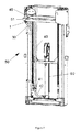
Figure 7 discloses alifting mast 50 for an industrial truck with an hydraulic hose comprising twosections hydraulic hose device 1 is situated. The described embodiment shall not be seen as limiting for the invention. Details from the above general detailed description shall be usable to modify the embodiments described above. For example bent forks should be able to be applied, as well as alternative designs of the coupling element and the attachment section of the connecting element.Figure 7 also discloses anhydraulic cylinder 60 and thesection 40 of the hose that is exposed to the pretension of the hose. Thesection 40 is attached at theattachment point 51 and thereafter runs over a group of rollers down to anattachment point 41 in the lower part of themast 50. Starting from this attachment point, a shorterhydraulic hose section 42 runs to the hydraulic cylinder. - According to still a further embodiment disclosed in
figure 8 and 9 can be seen how thecoupling element 2 has attached casings 23'. The casings 23' are attached in thefirst waist 6. The casings 23' comprises aconical section 24 starting with a diameter that provides for that an hydraulic hose is pressed onto thecoupling element 2 and a terminating in connecting with thefirst waist 6. The casings 23' keep the hydraulic hose sections in place and give protection against wear of the connected hydraulic hose section ends. Thesecond waist 5 also becomes as visible infigure 8 and 9 more uncovered. The casings 23'conical section 24 gives an advantageous freedom of movement for the hydraulic hose unit when being connected to a connecting element. Theconical section 24 of the casings 23' also give the advantage that respectivehydraulic hose section coupling element 2 in vicinity of the hydraulic hose section ends 30, 40, which thereby prevents leakage effectively. Also the casings 23' themselves are connected to thecoupling element 2 in a sealing manner, which further improves the sealing. The design is of course not limited tofigure 8 and 9 , it is also of course possible that one hydraulic hose section can have a casing 23' with aconical section 24 and the other hydraulic hose section can be provided with acasing 23 without conical section. The casings 23' are provided withribbing 25 on the inside to increase engagement with respective hydraulic hose section. - According to a method a hydraulic hose is attached in a pretension manner according to the following steps by:
- providing a first hydraulic hose section
- providing a second hydraulic hose section
- providing a coupling element
- uniting the first and the second hydraulic hose section with said coupling element to a hydraulic hose unit
- providing a connecting element intended to at least partly surround the coupling element
- attaching the coupling element to a lift mast of an industrial truck
- apply the hydraulic hose unit to the connecting element in such a way so the coupling element and the connecting element is connected to each other for an attaching of the hydraulic hose unit pretension on the lift mast of the industrial truck, but that the hydraulic hose unit is at least partly movable in relation to the connecting element.
- In this way a good securing of the hydraulic hose in a pretension with few comprised parts and in spite of allowing a certain mobility between the hydraulic hose and the connecting element a good retaining of the pretension hydraulic hose unit is provided for.
- The method also comprises a design of a lift mast for an industrial truck with the hydraulic hose device according to the above.
- With industrial truck is preferably meant a forklift truck. More preferably a forklift truck for indoor use is meant, a so called warehouse truck. Even more précised is meant an electric warehouse truck. An even more précised is meant a warehouse truck with support legs, a so called support leg truck and comprising a lift mast. The device and method are particularly well suitable for the types of industrial fork lift trucks that are used inside close to warehouse shelves walls and narrow spaces where a loosening hydraulic hose can have serious consequences with hooking in problems and destroyed goods.
wherein said coupling element comprises an indentation in which a connecting element can connect at least in a partly mobile manner, wherein the connecting element is arranged such that it can be attached to a lift mast of an industrial truck,
wherein at connecting between the coupling element and the connecting element attached to the lift mast, the hydraulic hose is attached to the lift mast in such a manner that force components in the longitudinal direction of the mast can be received by the hydraulic hose device, together with that the hydraulic hose unit remains at least partly mobile in relation to the connecting element.
Claims (12)
- A hydraulic hose device (1) for a lift mast (50) for an industrial truck, which comprises- a first hydraulic hose section (30)- a second hydraulic hose section (40)- a coupling element (2) intended to unite said first hydraulic hose section (30) and said second hydraulic hose section (40)
wherein said coupling element (2) is arranged such that it can seal the first hydraulic hose section (30) against hydraulic liquid leakage , and that it can seal the second hydraulic hose section (40) against hydraulic liquid leakage, and that it when sealing said hydraulic hose sections (30, 40) simultaneously unites these parts to a hydraulic hose unit,
wherein said coupling element (2) comprises an indentation (8) in which a connecting element (10) can connect at least in a partly mobile manner, wherein the connecting element (10) is arranged such that it can be attached to a lift mast (50) of an industrial truck,
wherein at connecting between the coupling element (2) and the connecting element (10) attached to the lift mast (50), the hydraulic hose is attached to the lift mast (50) in such a manner that force components in the longitudinal direction of the mast can be received by the hydraulic hose device (1), together with that the hydraulic hose unit remains at least partly mobile in relation to the connecting element (10). - A hydraulic hose device (1) according to claim 1, wherein the indentation (8) in the coupling element (2) is designed with a waist surrounded by protrusions (7) constituting stops for an attached hydraulic hose unit's movement on the coupling element (2).
- A hydraulic hose device (1) according to any of the preceding claims, wherein the connecting element (10) is designed with two forks and that the hydraulic hose unit via the stop/s on the coupling unit (10) is secured from leaving the connecting element's (10) nip in all directions, except for the fork direction for the connecting element (10).
- A hydraulic hose device (1) according to claim 3, wherein the hydraulic unit device (1) comprises a closing element (22) for closing of the nip (14) between the forks (11, 12) on the connecting element (10) such that securing of the hydraulic hose unit can be achieved against movement in the connecting element's (10) fork direction.
- A hydraulic hose device (1) according to claim 4, wherein the closing element (20) is constituted of a detachable clamp.
- A hydraulic hose device (1) according to any of the claims 3 to 5, wherein the forks (11, 12) are arranged to point in a direction that differs from a plane that runs in a direction in parallel with the essentially flat surface in the area adjacent where the forks (11, 12) protrudes from the connecting element (10), such that it also gives possibility for the connecting element's (10) forks (11, 12) to also receive force components in directions that runs in parallel with said plane.
- A hydraulic hose device (1) according to any of the preceding claims, wherein the device comprises casings (23, 23') on the outside of the ends of respective hydraulic hose section (30, 40).
- A hydraulic hose device (1) according to claim 7, wherein the casings (23, 23') is attached to a first waist (6) on the coupling element (2).
- A hydraulic hose device (1) according to claim 7 or 8, wherein the casings (23, 23') comprises a conic section (24), wherein the conic section's smaller diameter is positioned adjacent the first waist (6).
- A method to attach a hydraulic hose to a lifting mast for an industrial truck comprising the steps of:- providing a first hydraulic hose section (30)- providing a second hydraulic hose section (40)- providing a coupling element (2)- uniting the first and the second hydraulic hose section (30, 40) with said coupling element (2) to a hydraulic hose unit- providing to a connecting element (10) intended to at least surround the coupling element (2)- attaching of the connecting element (10) to a lifting mast for an industrial truck- applying the hydraulic hose unit to the connecting element (10) in such a way that the coupling element (2) and the connecting element (10) are attached to each other for an attachment of the hydraulic hose unit in a pretension manner on the lift mast (50) for the industrial truck, but the hydraulic hose unit is at least partly mobile in relation to the connecting element (10).
- A method of realizing a lift mast for an industrial truck wherein the method comprises: performing a method according to claim 10, with a device (1) according to any of the claims 1 to 9.
- Industrial truck characterized in that it comprises a device according to any of the claims 1 to 9, mounted with a method according to any of the clams 1 to 11.
Applications Claiming Priority (2)
| Application Number | Priority Date | Filing Date | Title |
|---|---|---|---|
| SE1150916 | 2011-10-04 | ||
| SE1250338A SE1250338A1 (en) | 2011-10-04 | 2012-04-03 | Device and method for attaching pre-tensioned hydraulic hose and industrial truck |
Publications (3)
| Publication Number | Publication Date |
|---|---|
| EP2578915A2 true EP2578915A2 (en) | 2013-04-10 |
| EP2578915A3 EP2578915A3 (en) | 2014-09-03 |
| EP2578915B1 EP2578915B1 (en) | 2016-11-23 |
Family
ID=46968066
Family Applications (1)
| Application Number | Title | Priority Date | Filing Date |
|---|---|---|---|
| EP12186914.3A Active EP2578915B1 (en) | 2011-10-04 | 2012-10-02 | Device and method for attaching a hydraulic hose for an industrial truck |
Country Status (2)
| Country | Link |
|---|---|
| EP (1) | EP2578915B1 (en) |
| SE (1) | SE1250338A1 (en) |
Cited By (3)
| Publication number | Priority date | Publication date | Assignee | Title |
|---|---|---|---|---|
| ITUB20153702A1 (en) * | 2015-09-17 | 2015-12-17 | Verum Italy S R L | HYDRAULIC UNIVERSAL CONNECTION SYSTEM. |
| CN111851222A (en) * | 2020-07-15 | 2020-10-30 | 徐州新路智能科技有限公司 | Hydraulic hose telescoping device suitable for crawler-type curb paver |
| EP3798371A1 (en) * | 2019-09-26 | 2021-03-31 | Deere & Company | Hose connection system |
Family Cites Families (4)
| Publication number | Priority date | Publication date | Assignee | Title |
|---|---|---|---|---|
| US1354480A (en) * | 1919-01-30 | 1920-10-05 | David M Hutchinson | Hose-coupling |
| US4553638A (en) * | 1984-07-13 | 1985-11-19 | Allis-Chalmers Corporation | Hose tensioning device |
| JPH0231658Y2 (en) * | 1986-10-28 | 1990-08-27 | ||
| SE0801631L (en) * | 2008-07-07 | 2010-01-08 | Nordhydraulic Ab | Suspension device for hoses |
-
2012
- 2012-04-03 SE SE1250338A patent/SE1250338A1/en not_active Application Discontinuation
- 2012-10-02 EP EP12186914.3A patent/EP2578915B1/en active Active
Non-Patent Citations (1)
| Title |
|---|
| None |
Cited By (4)
| Publication number | Priority date | Publication date | Assignee | Title |
|---|---|---|---|---|
| ITUB20153702A1 (en) * | 2015-09-17 | 2015-12-17 | Verum Italy S R L | HYDRAULIC UNIVERSAL CONNECTION SYSTEM. |
| WO2017046823A1 (en) * | 2015-09-17 | 2017-03-23 | Verum Italy S.R.L | Universal hydraulic connection system |
| EP3798371A1 (en) * | 2019-09-26 | 2021-03-31 | Deere & Company | Hose connection system |
| CN111851222A (en) * | 2020-07-15 | 2020-10-30 | 徐州新路智能科技有限公司 | Hydraulic hose telescoping device suitable for crawler-type curb paver |
Also Published As
| Publication number | Publication date |
|---|---|
| EP2578915B1 (en) | 2016-11-23 |
| SE1250338A1 (en) | 2013-04-05 |
| EP2578915A3 (en) | 2014-09-03 |
Similar Documents
| Publication | Publication Date | Title |
|---|---|---|
| EP2578915B1 (en) | Device and method for attaching a hydraulic hose for an industrial truck | |
| US6758500B2 (en) | Flared ends conduit coupling | |
| US9810322B2 (en) | Piston unit of a working cylinder | |
| WO2007102002A3 (en) | A spreader assembly | |
| EP2490974A1 (en) | Means of attachment and load lifting system for use with such a means of attachment | |
| CA2797176A1 (en) | One-touch pipe connection device | |
| US8087227B2 (en) | Connector | |
| US20170129697A1 (en) | Interconnect for freight containers | |
| US20050069379A1 (en) | Stopping means | |
| AU2016324352B2 (en) | Intermodal container corner fitting connector | |
| EP2362024A2 (en) | Quick hitch for a digging or loading tool | |
| CN105300793B (en) | The resistance to plucking that wallboard sockets part examines special fixture and equipment | |
| EP2799803B1 (en) | Lifting System for Low Profile Element Baskets for Rotary Regenerative Air Preheaters | |
| AU2013203312B2 (en) | Readily releasable wedge assembly for holding a wire rope in a socket | |
| CN217538622U (en) | Connecting structure for connecting power head and drilling machine | |
| JP3179886U (en) | Tombstone suspension | |
| CN208830820U (en) | A kind of inserted overturn-preventing limiting device of mast lifting construction | |
| KR100940931B1 (en) | Disassembly Lug | |
| CN201883923U (en) | Multi-purpose ladder for aloft work | |
| CN216687109U (en) | Hoisting auxiliary tool | |
| CN210290607U (en) | Engine upper part sling chain | |
| CN216155317U (en) | Universal hoisting ring convenient for dismounting bolt | |
| CN210340150U (en) | Enhanced crawler crane pull pipe and crane | |
| NO320661B1 (en) | Device for interconnecting pipelines | |
| CN109057507A (en) | A kind of inserted overturn-preventing limiting device of mast lifting construction and its construction method |
Legal Events
| Date | Code | Title | Description |
|---|---|---|---|
| PUAI | Public reference made under article 153(3) epc to a published international application that has entered the european phase |
Free format text: ORIGINAL CODE: 0009012 |
|
| AK | Designated contracting states |
Kind code of ref document: A2 Designated state(s): AL AT BE BG CH CY CZ DE DK EE ES FI FR GB GR HR HU IE IS IT LI LT LU LV MC MK MT NL NO PL PT RO RS SE SI SK SM TR |
|
| AX | Request for extension of the european patent |
Extension state: BA ME |
|
| PUAL | Search report despatched |
Free format text: ORIGINAL CODE: 0009013 |
|
| AK | Designated contracting states |
Kind code of ref document: A3 Designated state(s): AL AT BE BG CH CY CZ DE DK EE ES FI FR GB GR HR HU IE IS IT LI LT LU LV MC MK MT NL NO PL PT RO RS SE SI SK SM TR |
|
| AX | Request for extension of the european patent |
Extension state: BA ME |
|
| RIC1 | Information provided on ipc code assigned before grant |
Ipc: F16L 31/00 20060101ALI20140730BHEP Ipc: B66F 9/20 20060101ALI20140730BHEP Ipc: F16L 3/18 20060101ALI20140730BHEP Ipc: F16L 3/12 20060101AFI20140730BHEP Ipc: B66F 9/08 20060101ALI20140730BHEP |
|
| 17P | Request for examination filed |
Effective date: 20150210 |
|
| RBV | Designated contracting states (corrected) |
Designated state(s): AL AT BE BG CH CY CZ DE DK EE ES FI FR GB GR HR HU IE IS IT LI LT LU LV MC MK MT NL NO PL PT RO RS SE SI SK SM TR |
|
| 17Q | First examination report despatched |
Effective date: 20150716 |
|
| GRAP | Despatch of communication of intention to grant a patent |
Free format text: ORIGINAL CODE: EPIDOSNIGR1 |
|
| INTG | Intention to grant announced |
Effective date: 20160519 |
|
| GRAS | Grant fee paid |
Free format text: ORIGINAL CODE: EPIDOSNIGR3 |
|
| RAP1 | Party data changed (applicant data changed or rights of an application transferred) |
Owner name: TOYOTA MATERIAL HANDLING MANUFACTURING SWEDEN AB |
|
| GRAA | (expected) grant |
Free format text: ORIGINAL CODE: 0009210 |
|
| AK | Designated contracting states |
Kind code of ref document: B1 Designated state(s): AL AT BE BG CH CY CZ DE DK EE ES FI FR GB GR HR HU IE IS IT LI LT LU LV MC MK MT NL NO PL PT RO RS SE SI SK SM TR |
|
| REG | Reference to a national code |
Ref country code: GB Ref legal event code: FG4D |
|
| REG | Reference to a national code |
Ref country code: CH Ref legal event code: EP |
|
| REG | Reference to a national code |
Ref country code: IE Ref legal event code: FG4D |
|
| REG | Reference to a national code |
Ref country code: AT Ref legal event code: REF Ref document number: 848227 Country of ref document: AT Kind code of ref document: T Effective date: 20161215 |
|
| REG | Reference to a national code |
Ref country code: SE Ref legal event code: TRGR |
|
| REG | Reference to a national code |
Ref country code: DE Ref legal event code: R096 Ref document number: 602012025659 Country of ref document: DE |
|
| PG25 | Lapsed in a contracting state [announced via postgrant information from national office to epo] |
Ref country code: LV Free format text: LAPSE BECAUSE OF FAILURE TO SUBMIT A TRANSLATION OF THE DESCRIPTION OR TO PAY THE FEE WITHIN THE PRESCRIBED TIME-LIMIT Effective date: 20161123 |
|
| REG | Reference to a national code |
Ref country code: LT Ref legal event code: MG4D |
|
| REG | Reference to a national code |
Ref country code: NL Ref legal event code: MP Effective date: 20161123 |
|
| REG | Reference to a national code |
Ref country code: AT Ref legal event code: MK05 Ref document number: 848227 Country of ref document: AT Kind code of ref document: T Effective date: 20161123 |
|
| PG25 | Lapsed in a contracting state [announced via postgrant information from national office to epo] |
Ref country code: LT Free format text: LAPSE BECAUSE OF FAILURE TO SUBMIT A TRANSLATION OF THE DESCRIPTION OR TO PAY THE FEE WITHIN THE PRESCRIBED TIME-LIMIT Effective date: 20161123 Ref country code: GR Free format text: LAPSE BECAUSE OF FAILURE TO SUBMIT A TRANSLATION OF THE DESCRIPTION OR TO PAY THE FEE WITHIN THE PRESCRIBED TIME-LIMIT Effective date: 20170224 Ref country code: NO Free format text: LAPSE BECAUSE OF FAILURE TO SUBMIT A TRANSLATION OF THE DESCRIPTION OR TO PAY THE FEE WITHIN THE PRESCRIBED TIME-LIMIT Effective date: 20170223 Ref country code: NL Free format text: LAPSE BECAUSE OF FAILURE TO SUBMIT A TRANSLATION OF THE DESCRIPTION OR TO PAY THE FEE WITHIN THE PRESCRIBED TIME-LIMIT Effective date: 20161123 |
|
| PG25 | Lapsed in a contracting state [announced via postgrant information from national office to epo] |
Ref country code: PL Free format text: LAPSE BECAUSE OF FAILURE TO SUBMIT A TRANSLATION OF THE DESCRIPTION OR TO PAY THE FEE WITHIN THE PRESCRIBED TIME-LIMIT Effective date: 20161123 Ref country code: PT Free format text: LAPSE BECAUSE OF FAILURE TO SUBMIT A TRANSLATION OF THE DESCRIPTION OR TO PAY THE FEE WITHIN THE PRESCRIBED TIME-LIMIT Effective date: 20170323 Ref country code: HR Free format text: LAPSE BECAUSE OF FAILURE TO SUBMIT A TRANSLATION OF THE DESCRIPTION OR TO PAY THE FEE WITHIN THE PRESCRIBED TIME-LIMIT Effective date: 20161123 Ref country code: RS Free format text: LAPSE BECAUSE OF FAILURE TO SUBMIT A TRANSLATION OF THE DESCRIPTION OR TO PAY THE FEE WITHIN THE PRESCRIBED TIME-LIMIT Effective date: 20161123 Ref country code: FI Free format text: LAPSE BECAUSE OF FAILURE TO SUBMIT A TRANSLATION OF THE DESCRIPTION OR TO PAY THE FEE WITHIN THE PRESCRIBED TIME-LIMIT Effective date: 20161123 Ref country code: ES Free format text: LAPSE BECAUSE OF FAILURE TO SUBMIT A TRANSLATION OF THE DESCRIPTION OR TO PAY THE FEE WITHIN THE PRESCRIBED TIME-LIMIT Effective date: 20161123 Ref country code: AT Free format text: LAPSE BECAUSE OF FAILURE TO SUBMIT A TRANSLATION OF THE DESCRIPTION OR TO PAY THE FEE WITHIN THE PRESCRIBED TIME-LIMIT Effective date: 20161123 |
|
| PG25 | Lapsed in a contracting state [announced via postgrant information from national office to epo] |
Ref country code: CZ Free format text: LAPSE BECAUSE OF FAILURE TO SUBMIT A TRANSLATION OF THE DESCRIPTION OR TO PAY THE FEE WITHIN THE PRESCRIBED TIME-LIMIT Effective date: 20161123 Ref country code: EE Free format text: LAPSE BECAUSE OF FAILURE TO SUBMIT A TRANSLATION OF THE DESCRIPTION OR TO PAY THE FEE WITHIN THE PRESCRIBED TIME-LIMIT Effective date: 20161123 Ref country code: SK Free format text: LAPSE BECAUSE OF FAILURE TO SUBMIT A TRANSLATION OF THE DESCRIPTION OR TO PAY THE FEE WITHIN THE PRESCRIBED TIME-LIMIT Effective date: 20161123 Ref country code: DK Free format text: LAPSE BECAUSE OF FAILURE TO SUBMIT A TRANSLATION OF THE DESCRIPTION OR TO PAY THE FEE WITHIN THE PRESCRIBED TIME-LIMIT Effective date: 20161123 Ref country code: RO Free format text: LAPSE BECAUSE OF FAILURE TO SUBMIT A TRANSLATION OF THE DESCRIPTION OR TO PAY THE FEE WITHIN THE PRESCRIBED TIME-LIMIT Effective date: 20161123 |
|
| REG | Reference to a national code |
Ref country code: DE Ref legal event code: R097 Ref document number: 602012025659 Country of ref document: DE |
|
| PG25 | Lapsed in a contracting state [announced via postgrant information from national office to epo] |
Ref country code: SM Free format text: LAPSE BECAUSE OF FAILURE TO SUBMIT A TRANSLATION OF THE DESCRIPTION OR TO PAY THE FEE WITHIN THE PRESCRIBED TIME-LIMIT Effective date: 20161123 Ref country code: BE Free format text: LAPSE BECAUSE OF FAILURE TO SUBMIT A TRANSLATION OF THE DESCRIPTION OR TO PAY THE FEE WITHIN THE PRESCRIBED TIME-LIMIT Effective date: 20161123 Ref country code: BG Free format text: LAPSE BECAUSE OF FAILURE TO SUBMIT A TRANSLATION OF THE DESCRIPTION OR TO PAY THE FEE WITHIN THE PRESCRIBED TIME-LIMIT Effective date: 20170223 |
|
| REG | Reference to a national code |
Ref country code: FR Ref legal event code: PLFP Year of fee payment: 6 |
|
| PLBE | No opposition filed within time limit |
Free format text: ORIGINAL CODE: 0009261 |
|
| STAA | Information on the status of an ep patent application or granted ep patent |
Free format text: STATUS: NO OPPOSITION FILED WITHIN TIME LIMIT |
|
| 26N | No opposition filed |
Effective date: 20170824 |
|
| PG25 | Lapsed in a contracting state [announced via postgrant information from national office to epo] |
Ref country code: SI Free format text: LAPSE BECAUSE OF FAILURE TO SUBMIT A TRANSLATION OF THE DESCRIPTION OR TO PAY THE FEE WITHIN THE PRESCRIBED TIME-LIMIT Effective date: 20161123 |
|
| PG25 | Lapsed in a contracting state [announced via postgrant information from national office to epo] |
Ref country code: MC Free format text: LAPSE BECAUSE OF FAILURE TO SUBMIT A TRANSLATION OF THE DESCRIPTION OR TO PAY THE FEE WITHIN THE PRESCRIBED TIME-LIMIT Effective date: 20161123 |
|
| REG | Reference to a national code |
Ref country code: CH Ref legal event code: PL |
|
| REG | Reference to a national code |
Ref country code: IE Ref legal event code: MM4A |
|
| PG25 | Lapsed in a contracting state [announced via postgrant information from national office to epo] |
Ref country code: LI Free format text: LAPSE BECAUSE OF NON-PAYMENT OF DUE FEES Effective date: 20171031 Ref country code: CH Free format text: LAPSE BECAUSE OF NON-PAYMENT OF DUE FEES Effective date: 20171031 Ref country code: LU Free format text: LAPSE BECAUSE OF NON-PAYMENT OF DUE FEES Effective date: 20171002 |
|
| PG25 | Lapsed in a contracting state [announced via postgrant information from national office to epo] |
Ref country code: MT Free format text: LAPSE BECAUSE OF NON-PAYMENT OF DUE FEES Effective date: 20171002 |
|
| REG | Reference to a national code |
Ref country code: FR Ref legal event code: PLFP Year of fee payment: 7 |
|
| PG25 | Lapsed in a contracting state [announced via postgrant information from national office to epo] |
Ref country code: IE Free format text: LAPSE BECAUSE OF NON-PAYMENT OF DUE FEES Effective date: 20171002 |
|
| PG25 | Lapsed in a contracting state [announced via postgrant information from national office to epo] |
Ref country code: HU Free format text: LAPSE BECAUSE OF FAILURE TO SUBMIT A TRANSLATION OF THE DESCRIPTION OR TO PAY THE FEE WITHIN THE PRESCRIBED TIME-LIMIT; INVALID AB INITIO Effective date: 20121002 |
|
| PG25 | Lapsed in a contracting state [announced via postgrant information from national office to epo] |
Ref country code: CY Free format text: LAPSE BECAUSE OF NON-PAYMENT OF DUE FEES Effective date: 20161123 |
|
| PG25 | Lapsed in a contracting state [announced via postgrant information from national office to epo] |
Ref country code: MK Free format text: LAPSE BECAUSE OF FAILURE TO SUBMIT A TRANSLATION OF THE DESCRIPTION OR TO PAY THE FEE WITHIN THE PRESCRIBED TIME-LIMIT Effective date: 20161123 |
|
| PGFP | Annual fee paid to national office [announced via postgrant information from national office to epo] |
Ref country code: IT Payment date: 20191024 Year of fee payment: 8 |
|
| PG25 | Lapsed in a contracting state [announced via postgrant information from national office to epo] |
Ref country code: TR Free format text: LAPSE BECAUSE OF FAILURE TO SUBMIT A TRANSLATION OF THE DESCRIPTION OR TO PAY THE FEE WITHIN THE PRESCRIBED TIME-LIMIT Effective date: 20161123 |
|
| PG25 | Lapsed in a contracting state [announced via postgrant information from national office to epo] |
Ref country code: AL Free format text: LAPSE BECAUSE OF FAILURE TO SUBMIT A TRANSLATION OF THE DESCRIPTION OR TO PAY THE FEE WITHIN THE PRESCRIBED TIME-LIMIT Effective date: 20161123 Ref country code: IS Free format text: LAPSE BECAUSE OF FAILURE TO SUBMIT A TRANSLATION OF THE DESCRIPTION OR TO PAY THE FEE WITHIN THE PRESCRIBED TIME-LIMIT Effective date: 20170323 |
|
| PG25 | Lapsed in a contracting state [announced via postgrant information from national office to epo] |
Ref country code: IT Free format text: LAPSE BECAUSE OF NON-PAYMENT OF DUE FEES Effective date: 20201002 |
|
| P01 | Opt-out of the competence of the unified patent court (upc) registered |
Effective date: 20230526 |
|
| PGFP | Annual fee paid to national office [announced via postgrant information from national office to epo] |
Ref country code: DE Payment date: 20251028 Year of fee payment: 14 |
|
| PGFP | Annual fee paid to national office [announced via postgrant information from national office to epo] |
Ref country code: GB Payment date: 20251021 Year of fee payment: 14 |
|
| PGFP | Annual fee paid to national office [announced via postgrant information from national office to epo] |
Ref country code: FR Payment date: 20251027 Year of fee payment: 14 |
|
| PGFP | Annual fee paid to national office [announced via postgrant information from national office to epo] |
Ref country code: SE Payment date: 20251014 Year of fee payment: 14 |