EP2578900A1 - Method for manufacturing leaf springs - Google Patents
Method for manufacturing leaf springs Download PDFInfo
- Publication number
- EP2578900A1 EP2578900A1 EP11792241.9A EP11792241A EP2578900A1 EP 2578900 A1 EP2578900 A1 EP 2578900A1 EP 11792241 A EP11792241 A EP 11792241A EP 2578900 A1 EP2578900 A1 EP 2578900A1
- Authority
- EP
- European Patent Office
- Prior art keywords
- eye
- leading end
- eye portion
- facing
- reflection
- Prior art date
- Legal status (The legal status is an assumption and is not a legal conclusion. Google has not performed a legal analysis and makes no representation as to the accuracy of the status listed.)
- Granted
Links
Images



Classifications
-
- B—PERFORMING OPERATIONS; TRANSPORTING
- B24—GRINDING; POLISHING
- B24C—ABRASIVE OR RELATED BLASTING WITH PARTICULATE MATERIAL
- B24C1/00—Methods for use of abrasive blasting for producing particular effects; Use of auxiliary equipment in connection with such methods
- B24C1/10—Methods for use of abrasive blasting for producing particular effects; Use of auxiliary equipment in connection with such methods for compacting surfaces, e.g. shot-peening
-
- B—PERFORMING OPERATIONS; TRANSPORTING
- B21—MECHANICAL METAL-WORKING WITHOUT ESSENTIALLY REMOVING MATERIAL; PUNCHING METAL
- B21D—WORKING OR PROCESSING OF SHEET METAL OR METAL TUBES, RODS OR PROFILES WITHOUT ESSENTIALLY REMOVING MATERIAL; PUNCHING METAL
- B21D53/00—Making other particular articles
- B21D53/88—Making other particular articles other parts for vehicles, e.g. cowlings, mudguards
- B21D53/886—Making other particular articles other parts for vehicles, e.g. cowlings, mudguards leaf springs
-
- B—PERFORMING OPERATIONS; TRANSPORTING
- B24—GRINDING; POLISHING
- B24C—ABRASIVE OR RELATED BLASTING WITH PARTICULATE MATERIAL
- B24C3/00—Abrasive blasting machines or devices; Plants
- B24C3/32—Abrasive blasting machines or devices; Plants designed for abrasive blasting of particular work, e.g. the internal surfaces of cylinder blocks
- B24C3/325—Abrasive blasting machines or devices; Plants designed for abrasive blasting of particular work, e.g. the internal surfaces of cylinder blocks for internal surfaces, e.g. of tubes
-
- F—MECHANICAL ENGINEERING; LIGHTING; HEATING; WEAPONS; BLASTING
- F16—ENGINEERING ELEMENTS AND UNITS; GENERAL MEASURES FOR PRODUCING AND MAINTAINING EFFECTIVE FUNCTIONING OF MACHINES OR INSTALLATIONS; THERMAL INSULATION IN GENERAL
- F16F—SPRINGS; SHOCK-ABSORBERS; MEANS FOR DAMPING VIBRATION
- F16F1/00—Springs
- F16F1/02—Springs made of steel or other material having low internal friction; Wound, torsion, leaf, cup, ring or the like springs, the material of the spring not being relevant
- F16F1/18—Leaf springs
-
- F—MECHANICAL ENGINEERING; LIGHTING; HEATING; WEAPONS; BLASTING
- F16—ENGINEERING ELEMENTS AND UNITS; GENERAL MEASURES FOR PRODUCING AND MAINTAINING EFFECTIVE FUNCTIONING OF MACHINES OR INSTALLATIONS; THERMAL INSULATION IN GENERAL
- F16F—SPRINGS; SHOCK-ABSORBERS; MEANS FOR DAMPING VIBRATION
- F16F1/00—Springs
- F16F1/02—Springs made of steel or other material having low internal friction; Wound, torsion, leaf, cup, ring or the like springs, the material of the spring not being relevant
- F16F1/18—Leaf springs
- F16F1/26—Attachments or mountings
- F16F1/28—Attachments or mountings comprising cylindrical metal pins pivoted in close-fitting sleeves
-
- F—MECHANICAL ENGINEERING; LIGHTING; HEATING; WEAPONS; BLASTING
- F16—ENGINEERING ELEMENTS AND UNITS; GENERAL MEASURES FOR PRODUCING AND MAINTAINING EFFECTIVE FUNCTIONING OF MACHINES OR INSTALLATIONS; THERMAL INSULATION IN GENERAL
- F16F—SPRINGS; SHOCK-ABSORBERS; MEANS FOR DAMPING VIBRATION
- F16F2226/00—Manufacturing; Treatments
-
- F—MECHANICAL ENGINEERING; LIGHTING; HEATING; WEAPONS; BLASTING
- F16—ENGINEERING ELEMENTS AND UNITS; GENERAL MEASURES FOR PRODUCING AND MAINTAINING EFFECTIVE FUNCTIONING OF MACHINES OR INSTALLATIONS; THERMAL INSULATION IN GENERAL
- F16F—SPRINGS; SHOCK-ABSORBERS; MEANS FOR DAMPING VIBRATION
- F16F2238/00—Type of springs or dampers
- F16F2238/02—Springs
- F16F2238/022—Springs leaf-like, e.g. of thin, planar-like metal
Definitions
- the present invention relates to a production method for a leaf spring having an eye portion at an end portion thereof.
- the present invention relates to an improvement in a shot peening method for an inner surface of the eye portion.
- Leaf springs or the like are used so as to be stacked in suspension apparatuses of vehicles (trucks or the like).
- steel is subjected to hot bending forming.
- Figs. 1A to 1C are diagrams which show a schematic construction of each processing of bending fonning.
- Fig. 1A is a diagram which shows leading end portion cutting
- Fig. 1B is a diagram which shows starting time of winding
- Fig. 1C is a diagram which shows ending time of winding.
- the bending forming first, one end portion side of the steel 1 is mounted on a dice 11, and the other end portion side thereof is fixed at a fixing member 12.
- one end portion of the steel 1 is abutted and pressed by a bending member 13 from one end of a curved portion of the dice 11 to the other end thereof.
- the one end portion of the steel 1 is bent, and a curved portion 1A is formed.
- one end portion of the curved portion 1A of the steel 1 is cut by a cutter 14.
- Fig. 1B while an upper surface of the one end portion side of the steel 1 is pressed by a pressing member 21, the curved portion 1A of the steel 1 is pressed and is wound toward the inside of the curved portion 1A by using a dice 22.
- Fig. 1C an eye portion 3 is formed. The above bending forming is performed on the other end portion of the steel 1, so that the steel 1, which has a leaf portion 2 and eye portions formed at both end portions of the leaf portion 2, is obtained.
- the steel 1 is subjected to heating processing (quenching and tempering), so that a leaf spring 10 is obtained.
- shots are injected from an impeller 25 of a shot peening apparatus to a surface (a surface at which the eye portions 3 are formed) of the leaf portion 2 of the leaf spring 10, and the surface of the leaf portion 2 is subjected to shot peening.
- compressive residual stress is provided to the surface of the leaf portion 2, and the durability is improved.
- a typical inner surface of the eye portion 3 as shown in Fig. 3 for example, a winding-start portion 4 of the inner surface of the eye portion 3 and a portion 5 facing the winding-start portion 4 have flattened shapes, an inner surface of the eye portion 3 is subjected to reaming. Thus, at least portions 3A are removed, and the inner surface of the eye portion 3 has a true circle shape, so that the leaf spring 10 shown in Fig. 4 is obtained.
- a bush (not shown in the Figures) is press-fitted into the inside of the eye portion 3, sand the leaf spring 10 is fixed to a vehicle body (not shown in the Figures) via the bush.
- the leaf spring 10 has been improved in weight reduction and high stress, so that generated stress at the eye portion 3 is increased.
- shot peening be performed on not only the leaf portion 2 but also the inner surface of the eye portion 3, and compressive residual stress be thereby provided to the inner surface of the eye portion 3.
- a shot peening apparatus 30 shown in Fig. 5 is used (see Patent Document 1, for example).
- the shot peening apparatus 30 is equipped with a nozzle 31 and a reflection member 32.
- the nuzzle 31 injects shots 33.
- the reflection member 32 has a reflection surface 32A reflecting the shots 33.
- the shots 33 are injected from the nozzle 31 to the reflection member 32, and the shots 33, which are reflected by the reflection surface 32A of the reflection member 32, are projected to the inner surface of the eye portion 3.
- the reflection member 32 is moved in the axial direction of the eye portion 3, so that the shot peening is performed on the inner surface of the eye portion 3, which extends from one opening (shot entrance side opening) to another opening (shot exit side opening) of the inner surface of the eye portion 3.
- Patent Document 1 is Japanese Unexamined Patent Application Publication No. H5-138535 .
- the shots are not projected to the leading end portion 6 of the eye portion 3 shown in Fig. 4 and the portion 7 (facing portion 7 of the eye portion 3) facing the leading end portion 6. Due to this, a problem of durability occurs at the facing portion 7 at a gap portion 8.
- An object of the present invention is to provide a production method for a leaf spring, which can improve the durability of the eye portion and the productivity and which can reduce the production cost.
- a production method for a leaf spring having a leaf portion and an eye portion formed at the leaf portion includes steps of: forming a gap portion between a leading end portion of the eye portion and a facing portion facing the leading end portion; shot peening at an inner surface of the eye portion by disposing a reflection member, which has a reflection surface, inside the eye portion, injecting shots from a nozzle to the reflection member, and projecting the shots, which are reflected by the reflection surface of the reflection member, to the inner surface of the eye portion, wherein in the forming of the gap portion, at a cross section perpendicular to an axial direction of the eye portion, the leading end portion of the eye portion faces the facing portion such that a straight line does not cross the leading end portion of the eye portion, the straight line connecting an intersection point and a center point of the reflection surface of the reflection member, the intersection point being between a perpendicular line and a surface of the facing portion, the perpendicular line extending from a leaf portion side end point
- Figs. 7A and 7B are diagrams which show a cross section shape of an eye portion 112 of each specific example of leaf springs of the present invention.
- the cross sectional shapes in Figs. 7A and 7B are cross sectional shapes perpendicular to an axial direction of the eye portion 112.
- reference numeral 111 denotes a leaf portion
- reference numeral 113 denotes a lead end portion of the eye portion 112
- reference numeral 113A denotes an end point (outside end point) of a leaf portion 111 side of the lead end portion 113
- reference numeral 113B denotes an end point (inside end point) of the lead end portion 113 which is opposite to the leaf portion 111 side
- reference numeral 114 denotes a facing portion (portion between intersection points T1 and T2 described below) which faces the lead end portion 113 of the eye portion 112
- reference symbol O denotes a center point of the eye portion 112
- reference symbols S1 and S2 denote a center point of reflection surface of a shot peening reflection member disposed inside the eye portion 112.
- Reference symbol H1 denotes a perpendicular line which extends from the outside end point 113A of the leading end portion 113 to the facing portion 114 surface
- reference symbol T1 denotes an intersection point between a facing portion 114 surface and the perpendicular line H1
- reference symbol H2 denotes a perpendicular line which extends from the inside end point 113B of the leading end portion 113 to the facing portion 114 surface of the eye portion 112
- preference symbol T2 denotes an intersection point between facing portion 114 surface of the eye portion 112 and the perpendicular line H2.
- Reference symbol L1 denotes a line which connects the center point O of the eye portion 112 (center point S1of the reflection surface) and the intersection point T1
- reference symbol L2 denotes a line which connects the center point S2 of the reflection surface and the intersection point T1.
- Reference numeral 115 denotes a gap portion which is formed between the leading end portion 113 and the facing portion 114
- reference symbol G denotes an interval of the gap portion 115.
- the line L1 which connects the center point S1 of the reflection surface and the intersection point T1 crosses the leading end portion 113 of the eye portion 112. Due to this, shots, which are reflected by the reflection surface of the reflection member, may collide with the inside end point 113B of the leading end portion 113, and it may be difficult for the shots to be projected to the surface of the facing portion 114 at the gap portion 115. In particular, the shots may not be projected to an outside boundary portion thereof. As a result, residual stress cannot be provided to the entire surface of the facing portion 114, so that the effects by the inner surface shot peening cannot be obtained.
- the center point S2 of the reflection surface of the reflection member does not correspond with the center point O of the eye portion 112, and the center point S2 is positioned at a side of the facing portion 114 (at a side lower than the center point O in the Figure), the line L2, which connects the center point S2 of the reflection surface and the intersection point T1, does not cross the leading end portion 113 of the eye portion 112.
- shots, which are reflected by the reflection surface of the reflection member does not collide with the inside end point 113B of the leading end portion 113, the shots are easily projected to the surface of the facing portion 114, and the shots can also reach the outside boundary portion thereof.
- residual stress can be provided to the entire surface of the facing portion 114 at the gap portion 115, so that the effects by the inner surface shot peening can be sufficiently obtained.
- the interval G of the gap portion 115 is greater than that in the feature shown in Fig. 7A .
- the line L1 which connects the center point S1 of the reflection surface and the intersection point T1
- the shots are easily projected to the surface of the facing portion 114, and the shots can also reach the outside boundary portion thereof.
- residual stress can be provided to the entire surface of the facing portion 114 at the gap portion 115, so that the effects by the inner surface shot peening can be sufficiently obtained.
- the shape and the interval G of the gap portion 115 and the center point 52 of reflection surface may be set to ones as shown in Figs. 7A and 7B .
- the present invention is not limited to these, and various modifications can be used within the range of the present invention.
- any features may be used in which the lines L1 and L2 may not cross the leading end portion 113.
- the leading end portion of the eye portion faces the facing portion such that the straight line does not cross the leading end portion of the eye portion.
- the straight line connects an intersection point and a center point of the reflection surface of the reflection member, the intersection point being between a perpendicular line and a surface of the facing portion, the perpendicular line extending from a leaf portion side end point of the leading end portion of the eye portion to the facing portion.
- the durability of the leaf spring can be improved, so that breakage of the leaf spring can be prevented.
- the interval of the gap can be set at a larger value. In this case, when the leaf portion is subjected to typical shot peening, the shots can also be projected to the surface of the facing portion at the gap portion, so that the durability of the leaf spring can be further improved. As a result, breakage of the leaf spring can be effectively prevented. In the forming of the eye portion, the cutting of the leading end portion is unnecessary, so that the productivity can be improved, and the production cost can be reduced.
- the production method for a leaf spring according to the above aspect of the present invention can use various structures.
- the center point of the reflection surface in order to use the feature in which the straight line connecting the center point of the reflection surface and the intersection point may not cross the leading end portion of the eye portion, at the cross section of the eye portion, in the reflection member, the center point of the reflection surface may be positioned more proximate to the facing portion than a center point of the eye portion.
- the reflection surface of the reflection member may have a shape (for example, conical shape) which is symmetrical about a center point thereof. It is desirable that incident angle of shot in shot peening be 30 degrees or more. Thus, in a feature in which an angle (shown in Figs.
- the durability of the leaf spring can be improved.
- the cutting of the leading end portion is unnecessary, so that the productivity can be improved and the production cost can be reduced.
- Reference numerals 110 and 120 denote a leaf spring
- reference numerals 111 and 121 denote a leaf portion
- reference numerals 112 and 122 denote an eye portion
- reference numerals 113 and 123 denote a lead end portion
- reference numeral 113A denotes an outside end point (leaf portion side end point)
- reference numeral 113B denotes an inside end point (end point opposite to the leaf portion side)
- reference numerals 114 and 124 denote a facing portion
- reference numerals 115 and 125 denote a gap portion
- reference symbol H1 denotes a perpendicular line
- reference symbol G denotes an interval of the gap portion
- reference symbol K denotes a region (facing portion surface)
- reference symbol L1 and L2 denote a line
- reference symbol O denotes a center point of the eye portion
- reference symbols S1 and S2 demote a center point of reflection surface
- reference symbol T1 denotes an intersection point
- a leaf spring 120 was produced such that a gap portion 125 was formed between a leading end portion 123 of the eye portion 122 and a facing portion 124.
- the thickness t of the leaf spring 120 was set at 12.5 mm, the inner diameter ⁇ of the eye portion 122 was set at 55 mm, and the width W of the leaf spring 120 was set at 70 mm.
- the leaf springs 120 in which the interval G of the gap portion 125 was set at 2.5 mm were used as comparative samples 11 and 12.
- the leaf spring 120 in which the interval G of the gap portion 125 was set at 7.0 mm was used as a comparative sample 13.
- the leaf spring 120 in which the interval G of the gap portion 125 was set at 7.5 mm was used as a sample 11 of the present invention.
- warm stress shot peening was performed on an upper surface of a leaf portion 121 of each sample.
- shot peening hereinafter referred to as “inner surface shot peening (inner surface SP)
- inner surface shot peening inner surface SP
- the reflection member 32 was disposed inside the eye portion 122, and the shots 33 were injected from the nozzle 31 to the reflection member 32.
- the reflection member 32 was moved in the axial direction in a condition in which the shots 33 were injected, so that the inner surface shot peening was performed on the inner surface of the eye portion 122 from the shot entrance side opening to shot exit side opening of the inner surface of the eye portion 3.
- Fig. 9 is a graph which shows the residual stress measurement results of the comparative sample 11.
- Fig. 10 is a graph which shows the residual stress measurement results of the comparative sample 12.
- Fig. 11 is a graph which shows the residual stress measurement results of the comparative sample 13.
- Fig. 12 is a graph which shows the residual stress measurement results of the sample 11 of the present invention.
- 9 to 12 denotes a distance obtained by using a point, which corresponds to the inside end point at the facing portion 124 of the eye portion 122, as the origin, and reference symbol K denotes a region (facing portion 124 surface) at which the gap portion 125 is formed.
- the comparative sample 12 which was subjected to the inner surface shot peening was much higher in residual stress of inner surface side of the eye portion 122 than the comparative sample 11 which was not subjected to the inner surface shot peening.
- the residual stress was higher at the leaf portion 121 side, and the effects by the warm stress shot peening could be obtained.
- the residual stress was greatly decreased from the leaf portion 121 side boundary of the region K to the eye portion 122 inner surface side, and the effects by the warm stress shot peening could not be obtained at the region K.
- the residual stress at the eye portion 122 inner surface side was higher, and the effects by the inner surface shot peening could be obtained.
- the residual stress was greatly decreased at the region K having the gap portion 125 formed thereat, and the effects by the inner surface shot peening could not be obtained at the region K.
- the sample 11 which was subjected to the inner surface shot peening was much higher in residual stress of inner surface side of the eye portion 122 than the comparative sample 13 which was not subjected to the inner surface shot peening.
- the sample 11 was much higher in residual stress of the region K having the eye portion 122 formed thereat than the comparative sample 13. It was confirmed that in the comparative sample 13, in comparison with the comparative sample 11, the residual stress was slightly higher at the region K, and the effects by the warm stress shot peening could be obtained.
- the residual stress was high uniformly from the leaf portion 121 to the eye portion 122 inner surface, a boundary portion between the region at which the effects by the warm stress shot peening could be obtained and the region at which the effects by the inner surface shot peening could be obtained was not emerged, and the shots were also sufficiently projected at the region K.
Landscapes
- Engineering & Computer Science (AREA)
- Mechanical Engineering (AREA)
- General Engineering & Computer Science (AREA)
- Springs (AREA)
- Vehicle Body Suspensions (AREA)
- Fluid-Damping Devices (AREA)
Abstract

Description
- The present invention relates to a production method for a leaf spring having an eye portion at an end portion thereof. In particular, the present invention relates to an improvement in a shot peening method for an inner surface of the eye portion.
- Leaf springs or the like are used so as to be stacked in suspension apparatuses of vehicles (trucks or the like). In a production method for this leaf spring, for example, steel is subjected to hot bending forming.
Figs. 1A to 1C are diagrams which show a schematic construction of each processing of bending fonning.Fig. 1A is a diagram which shows leading end portion cutting,Fig. 1B is a diagram which shows starting time of winding, andFig. 1C is a diagram which shows ending time of winding. In the bending forming, first, one end portion side of thesteel 1 is mounted on adice 11, and the other end portion side thereof is fixed at afixing member 12. Next, one end portion of thesteel 1 is abutted and pressed by abending member 13 from one end of a curved portion of thedice 11 to the other end thereof. Thus, the one end portion of thesteel 1, is bent, and acurved portion 1A is formed. - Next, as shown in
Fig. 1A , one end portion of thecurved portion 1A of thesteel 1 is cut by acutter 14. Next, as shown inFig. 1B , while an upper surface of the one end portion side of thesteel 1 is pressed by apressing member 21, thecurved portion 1A of thesteel 1 is pressed and is wound toward the inside of thecurved portion 1A by using adice 22. Thus, as shown inFig. 1C , aneye portion 3 is formed. The above bending forming is performed on the other end portion of thesteel 1, so that thesteel 1, which has aleaf portion 2 and eye portions formed at both end portions of theleaf portion 2, is obtained. - Next, the
steel 1 is subjected to heating processing (quenching and tempering), so that aleaf spring 10 is obtained. Next, as shown inFig. 2 , shots are injected from animpeller 25 of a shot peening apparatus to a surface (a surface at which theeye portions 3 are formed) of theleaf portion 2 of theleaf spring 10, and the surface of theleaf portion 2 is subjected to shot peening. Thus, compressive residual stress is provided to the surface of theleaf portion 2, and the durability is improved. - Next, since regarding a typical inner surface of the
eye portion 3 as shown inFig. 3 , for example, a winding-start portion 4 of the inner surface of theeye portion 3 and aportion 5 facing the winding-start portion 4 have flattened shapes, an inner surface of theeye portion 3 is subjected to reaming. Thus, at leastportions 3A are removed, and the inner surface of theeye portion 3 has a true circle shape, so that theleaf spring 10 shown inFig. 4 is obtained. Next, a bush (not shown in the Figures) is press-fitted into the inside of theeye portion 3, sand theleaf spring 10 is fixed to a vehicle body (not shown in the Figures) via the bush. - In recent years, the
leaf spring 10 has been improved in weight reduction and high stress, so that generated stress at theeye portion 3 is increased. Thus, it has been proposed that shot peening be performed on not only theleaf portion 2 but also the inner surface of theeye portion 3, and compressive residual stress be thereby provided to the inner surface of theeye portion 3. In the shot peening to the inner surface of theeye portion 3, ashot peening apparatus 30 shown inFig. 5 is used (seePatent Document 1, for example). - The
shot peening apparatus 30 is equipped with anozzle 31 and areflection member 32. Thenuzzle 31 injectsshots 33. Thereflection member 32 has areflection surface 32A reflecting theshots 33. In shot peening to the inner surface of theeye portion 3, shereflection member 32 is disposed inside theeye portion 3, theshots 33 are injected from thenozzle 31 to thereflection member 32, and theshots 33, which are reflected by thereflection surface 32A of thereflection member 32, are projected to the inner surface of theeye portion 3. In this case, thereflection member 32 is moved in the axial direction of theeye portion 3, so that the shot peening is performed on the inner surface of theeye portion 3, which extends from one opening (shot entrance side opening) to another opening (shot exit side opening) of the inner surface of theeye portion 3. -
Patent Document 1 is Japanese Unexamined Patent Application Publication No.H5-138535 - However, the shots are not projected to the leading
end portion 6 of theeye portion 3 shown inFig. 4 and the portion 7 (facingportion 7 of the eye portion 3) facing the leadingend portion 6. Due to this, a problem of durability occurs at the facingportion 7 at agap portion 8. - On the other hand, as shown in Fug. 6, when the leading
end portion 6 end the facingportion 7 are not parallel to each other, the strength for resisting the pullout load of the bush, which is press-fitted into the inside of theeye portion 3, may be weak. Due to this, when theeye portion 3 is formed, in the leading end portion cutting shown inFig. 1A , it is necessary to cut the leading end portion by thecutter 14. As a result, the material yield may be deteriorated, and the productivity and the production cost may be increased. - An object of the present invention is to provide a production method for a leaf spring, which can improve the durability of the eye portion and the productivity and which can reduce the production cost.
- According to one aspect of the present invention, a production method for a leaf spring having a leaf portion and an eye portion formed at the leaf portion, includes steps of: forming a gap portion between a leading end portion of the eye portion and a facing portion facing the leading end portion; shot peening at an inner surface of the eye portion by disposing a reflection member, which has a reflection surface, inside the eye portion, injecting shots from a nozzle to the reflection member, and projecting the shots, which are reflected by the reflection surface of the reflection member, to the inner surface of the eye portion, wherein in the forming of the gap portion, at a cross section perpendicular to an axial direction of the eye portion, the leading end portion of the eye portion faces the facing portion such that a straight line does not cross the leading end portion of the eye portion, the straight line connecting an intersection point and a center point of the reflection surface of the reflection member, the intersection point being between a perpendicular line and a surface of the facing portion, the perpendicular line extending from a leaf portion side end point of the leading end portion of the eye portion to the facing portion.
- In the production method for a leaf spring according to the above aspect of the present invention, the interval of the gap portion between the leading end portion of the eye portion and the facing portion is set as follows.
Figs. 7A and 7B are diagrams which show a cross section shape of aneye portion 112 of each specific example of leaf springs of the present invention. The cross sectional shapes inFigs. 7A and 7B are cross sectional shapes perpendicular to an axial direction of theeye portion 112. - In
Figs. 7A and 7B ,reference numeral 111 denotes a leaf portion,reference numeral 113 denotes a lead end portion of theeye portion 112,reference numeral 113A denotes an end point (outside end point) of aleaf portion 111 side of thelead end portion 113,reference numeral 113B denotes an end point (inside end point) of thelead end portion 113 which is opposite to theleaf portion 111 side,reference numeral 114 denotes a facing portion (portion between intersection points T1 and T2 described below) which faces thelead end portion 113 of theeye portion 112, reference symbol O denotes a center point of theeye portion 112, reference symbols S1 and S2 denote a center point of reflection surface of a shot peening reflection member disposed inside theeye portion 112. - Reference symbol H1 denotes a perpendicular line which extends from the
outside end point 113A of the leadingend portion 113 to the facingportion 114 surface, reference symbol T1 denotes an intersection point between a facingportion 114 surface and the perpendicular line H1, reference symbol H2 denotes a perpendicular line which extends from theinside end point 113B of the leadingend portion 113 to the facingportion 114 surface of theeye portion 112, and preference symbol T2 denotes an intersection point between facingportion 114 surface of theeye portion 112 and the perpendicular line H2. Reference symbol L1 denotes a line which connects the center point O of the eye portion 112 (center point S1of the reflection surface) and the intersection point T1, reference symbol L2 denotes a line which connects the center point S2 of the reflection surface and the intersection point T1.Reference numeral 115 denotes a gap portion which is formed between the leadingend portion 113 and the facingportion 114, and reference symbol G denotes an interval of thegap portion 115. - In a case in which shot peening (hereinafter referred to as "inner surface shot peening") is performed on the inner surface of the
eye portion 112 in a feature shown inFig. 7A , when the center point S1 or the reflection surface of the reflection member corresponds with the center point O of theeye portion 112, the line L1, which connects the center point S1 of the reflection surface and the intersection point T1, crosses the leadingend portion 113 of theeye portion 112. Due to this, shots, which are reflected by the reflection surface of the reflection member, may collide with theinside end point 113B of the leadingend portion 113, and it may be difficult for the shots to be projected to the surface of the facingportion 114 at thegap portion 115. In particular, the shots may not be projected to an outside boundary portion thereof. As a result, residual stress cannot be provided to the entire surface of the facingportion 114, so that the effects by the inner surface shot peening cannot be obtained. - In contrast, when the center point S2 of the reflection surface of the reflection member does not correspond with the center point O of the
eye portion 112, and the center point S2 is positioned at a side of the facing portion 114 (at a side lower than the center point O in the Figure), the line L2, which connects the center point S2 of the reflection surface and the intersection point T1, does not cross the leadingend portion 113 of theeye portion 112. Thus, shots, which are reflected by the reflection surface of the reflection member, does not collide with theinside end point 113B of the leadingend portion 113, the shots are easily projected to the surface of the facingportion 114, and the shots can also reach the outside boundary portion thereof. As a result, residual stress can be provided to the entire surface of the facingportion 114 at thegap portion 115, so that the effects by the inner surface shot peening can be sufficiently obtained. - In a feature shown in
Fig. 7B , the interval G of thegap portion 115 is greater than that in the feature shown inFig. 7A . In a case in which inner surface shot peening is performed, even when the center point S1 of the reflection surface of the reflection member corresponds with the center point O of theeye portion 112, the line L1, which connects the center point S1 of the reflection surface and the intersection point T1, does not cross theleading end portion 113 of theeye portion 112. Thus, shots, which are reflected by the reflection surface of the reflection member, does not collide with theinside end point 113B of theleading end portion 113, the shots are easily projected to the surface of the facingportion 114, and the shots can also reach the outside boundary portion thereof. As a result, residual stress can be provided to the entire surface of the facingportion 114 at thegap portion 115, so that the effects by the inner surface shot peening can be sufficiently obtained. - In the feature shown in
Fig. 7B , when the center point S2 of the reflection surface of the reflection member does not correspond with the center point O of theeye portion 112, and the center point S2 is positioned at a side of the facingportion 114, obviously, the line L2, which connects the center point 52 of the reflection surface and the intersection point T1, does not cross theleading end portion 113 of theeye portion 112. As a result, the effects by the inner surface shot peening can be sufficiently obtained. - In the above features, the shape and the interval G of the
gap portion 115 and the center point 52 of reflection surface may be set to ones as shown inFigs. 7A and 7B . The present invention is not limited to these, and various modifications can be used within the range of the present invention. For example, any features may be used in which the lines L1 and L2 may not cross theleading end portion 113. - As described above, in the production method for a leaf spring according to the above aspect of the present invention, in the forming of the gap portion, at a cross section perpendicular to an axial direction of the eye portion, the leading end portion of the eye portion faces the facing portion such that the straight line does not cross the leading end portion of the eye portion. In this case, the straight line connects an intersection point and a center point of the reflection surface of the reflection member, the intersection point being between a perpendicular line and a surface of the facing portion, the perpendicular line extending from a leaf portion side end point of the leading end portion of the eye portion to the facing portion. Thus, shots, which are reflected by the reflection surface of the reflection member in the shot peening, does not collide with the inside end point of the leading end portion, the shots are easily projected to the surface of the facing portion, and the shots can also reach the outside boundary portion thereof.
- As a result, residual stress can be provided to the entire surface of the facing portion at the gap portion, so that the effects by the inner surface shot peening can be sufficiently obtained. Therefore, the durability of the leaf spring can be improved, so that breakage of the leaf spring can be prevented. The interval of the gap can be set at a larger value. In this case, when the leaf portion is subjected to typical shot peening, the shots can also be projected to the surface of the facing portion at the gap portion, so that the durability of the leaf spring can be further improved. As a result, breakage of the leaf spring can be effectively prevented. In the forming of the eye portion, the cutting of the leading end portion is unnecessary, so that the productivity can be improved, and the production cost can be reduced.
- The production method for a leaf spring according to the above aspect of the present invention can use various structures. According to a desirable embodiment of the present invention, in order to use the feature in which the straight line connecting the center point of the reflection surface and the intersection point may not cross the leading end portion of the eye portion, at the cross section of the eye portion, in the reflection member, the center point of the reflection surface may be positioned more proximate to the facing portion than a center point of the eye portion.
- The reflection surface of the reflection member may have a shape (for example, conical shape) which is symmetrical about a center point thereof. It is desirable that incident angle of shot in shot peening be 30 degrees or more. Thus, in a feature in which an angle (shown in
Figs. 7A and7B) is set between the line, which connects the center point of the reflection surface and the intersection point, and the surface of the facing portion, it is desirable that the angle between the line L1, which connects the center point S1 of the reflection surface and the intersection point T1, and the surface of the facingportion 114 be 30 degrees or more, and it is desirable that the angle between the line L2, which connects the center point S2 of the reflection surface and the intersection point T1, and the surface of the facingportion 114 be 30 degrees or more. - According to the production method for a leaf spring of the present invention, the durability of the leaf spring can be improved. In addition, the cutting of the leading end portion is unnecessary, so that the productivity can be improved and the production cost can be reduced.
-
-
Figs. 1A to 1C are side views which show a schematic construction of each processing of bending forming.Fig. 1A is a side view which shows leading end portion cutting,Fig. 1B is a side view which shows starting time of winding, andFig. 1C is a side view which shows ending time of winding. -
Fig. 2 is a side view which shows an overall structure of a leaf spring. -
Fig. 3 is a cross sectional diagram which shows an inner surface shape of an eye portion of a leaf spring before reaming. -
Fig. 4 is a cross sectional diagram which shows an inner surface shape of an eye portion of a leaf spring after reaming. -
Fig. 5 is a cross sectional diagram which shows a schematic construction of shot peening apparatus for eye portion inner surfaces and which shows a condition in which shot peening is performed on an eye portion inner surface. -
Fig. 6 is a cross sectional diagram which shows an inner surface shape of an eye portion of a leaf spring of which leading end portion is not subjected to cutting in leading end portion cutting. -
Figs. 7A and 7B are cross sectional diagrams which show an inner surface shape of an eye portion of each specific example of leaf springs of the present invention. -
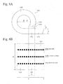
Fig. 8A is a diagram which shows an inner surface shape of an eye portion of a leaf spring produced in examples, andFig. 8B is a diagram which explains a portion at which residual stress measurement was performed. -
Fig. 9 is a graph which shows the residual stress measurement results of thecomparative sample 11. -
Fig. 10 is a graph which shows the residual stress measurement results of thecomparative sample 12. -
Fig. 11 is a graph which shows the residual stress measurement results of thecomparative sample 13. -
Fig. 12 is a graph which shows the residual stress measurement results of thesample 11 of the present invention. -
Reference numerals reference numerals reference numerals reference numerals reference numeral 113A denotes an outside end point (leaf portion side end point),reference numeral 113B denotes an inside end point (end point opposite to the leaf portion side),reference numerals reference numerals 115 and 125 denote a gap portion, reference symbol H1 denotes a perpendicular line, reference symbol G denotes an interval of the gap portion, reference symbol K denotes a region (facing portion surface), reference symbol L1 and L2 denote a line, reference symbol O denotes a center point of the eye portion, reference symbols S1 and S2 demote a center point of reflection surface, and reference symbol T1 denotes an intersection point. - The present invention will be explained hereinafter with reference to a specific example. In the example, effects by shot peening at an eye portion inner surface of a leaf spring were examined.
- In the example, after an eye portion was formed by bending forming at an end portion of steel, the steel was subjected to quenching and tempering, and a leading end portion of the eye portion of leaf spring was subjected to working. Thus, as shown in
Fig. 8A , aleaf spring 120 was produced such that a gap portion 125 was formed between aleading end portion 123 of theeye portion 122 and a facingportion 124. - The thickness t of the
leaf spring 120 was set at 12.5 mm, the inner diameter ϕ of theeye portion 122 was set at 55 mm, and the width W of theleaf spring 120 was set at 70 mm. The leaf springs 120 in which the interval G of the gap portion 125 was set at 2.5 mm were used ascomparative samples leaf spring 120 in which the interval G of the gap portion 125 was set at 7.0 mm was used as acomparative sample 13. Theleaf spring 120 in which the interval G of the gap portion 125 was set at 7.5 mm was used as asample 11 of the present invention. In thesample 11 and thecomparative sample 13, the feature (in which the line L1, which connects the center point O of the eye portion 112 (the center point S1 of the reflection surface of the reflection member) and the intersection point T1, does not cross theleading end portion 113 of the eye portion 112) shown inFig. 7B was set. - Next, warm stress shot peening was performed on an upper surface of a
leaf portion 121 of each sample. Next, by using theshot peening apparatus 30 shown inFig. 5 , shot peening (hereinafter referred to as "inner surface shot peening (inner surface SP)") was performed on each inner surface of theeye portions 112 of thesample 11 and thecomparative sample 12. In the inner surface shot peening, thereflection member 32 was disposed inside theeye portion 122, and theshots 33 were injected from thenozzle 31 to thereflection member 32. In this case, thereflection member 32 was moved in the axial direction in a condition in which theshots 33 were injected, so that the inner surface shot peening was performed on the inner surface of theeye portion 122 from the shot entrance side opening to shot exit side opening of the inner surface of theeye portion 3. - Next, regarding the
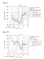
sample 11 and thecomparative samples 11 to 13, residual stress measurements were performed on the region (inFig. 8B ) extending from the inner surface of theeye portion 122 to theleaf portion 121. Reference symbol "●" inFig. 8B denotes a rough position of measurement point. The results are shown inFigs. 9 to 12 .Fig. 9 is a graph which shows the residual stress measurement results of thecomparative sample 11.Fig. 10 is a graph which shows the residual stress measurement results of thecomparative sample 12.Fig. 11 is a graph which shows the residual stress measurement results of thecomparative sample 13.Fig. 12 is a graph which shows the residual stress measurement results of thesample 11 of the present invention. As shown inFig. 8B , the distance X inFigs. 9 to 12 denotes a distance obtained by using a point, which corresponds to the inside end point at the facingportion 124 of theeye portion 122, as the origin, and reference symbol K denotes a region (facingportion 124 surface) at which the gap portion 125 is formed. - As understood from
Figs. 9 and 10 , in a case in which thecomparative samples comparative sample 12 which was subjected to the inner surface shot peening was much higher in residual stress of inner surface side of theeye portion 122 than thecomparative sample 11 which was not subjected to the inner surface shot peening. In thecomparative sample 11, the residual stress was higher at theleaf portion 121 side, and the effects by the warm stress shot peening could be obtained. However, it was confirmed that in thecomparative sample 11, the residual stress was greatly decreased from theleaf portion 121 side boundary of the region K to theeye portion 122 inner surface side, and the effects by the warm stress shot peening could not be obtained at the region K. In thecomparative sample 12, in comparison with thesample 11, the residual stress at theeye portion 122 inner surface side was higher, and the effects by the inner surface shot peening could be obtained. However, it was confirmed that in thecomparative sample 12, the residual stress was greatly decreased at the region K having the gap portion 125 formed thereat, and the effects by the inner surface shot peening could not be obtained at the region K. - As understood from
Figs. 11 and 12 , regarding thecomparative sample 13 and thesample 11 in which the interval G was set to be larger than that of conventional product, thesample 11 which was subjected to the inner surface shot peening was much higher in residual stress of inner surface side of theeye portion 122 than thecomparative sample 13 which was not subjected to the inner surface shot peening. In addition, thesample 11 was much higher in residual stress of the region K having theeye portion 122 formed thereat than thecomparative sample 13. It was confirmed that in thecomparative sample 13, in comparison with thecomparative sample 11, the residual stress was slightly higher at the region K, and the effects by the warm stress shot peening could be obtained. It was confirmed that in thesample 11, the residual stress was high uniformly from theleaf portion 121 to theeye portion 122 inner surface, a boundary portion between the region at which the effects by the warm stress shot peening could be obtained and the region at which the effects by the inner surface shot peening could be obtained was not emerged, and the shots were also sufficiently projected at the region K. - As described above, in the
comparative sample 12 in which the interval G was set at 2.5 mm which was equal to that of conventional product, even when the inner surface shot peening was performed, the effects by the inner surface shot peening could not be obtained at the region K having the gap portion 125 formed thereat. In contrast, in thesample 11 of the present invention in which the relationship between the line and the leading end portion of the eye portion was set within the present invention, when the inner surface shot peening was performed, the effects by the inner surface shot peening could be sufficiently obtained at the region K having the gap portion 125 formed thereat. In addition, it was confirmed that the effects by the warm stress shot peening, which was performed on the upper surface of theleaf portion 121, could also be obtained at the region K.
Claims (2)
- A production method for a leaf spring having a leaf portion and an eye portion formed at the leaf portion, comprising steps of:forming a gap portion between a leading end portion of the eye portion and a facing portion facing the leading end portion;shot peening at an inner surface of the eye portion by disposing a reflection member, which has a reflection surface, inside the eye portion, injecting shots from a nozzle to the reflection member, and projecting the shots, which are reflected by the reflection surface of the reflection member, to the inner surface of the eye portion,wherein in the forming of the gap portion, at a cross section perpendicular to an axial direction of the eye portion, the leading end portion of the eye portion faces the facing portion such that a straight line does not cross the leading end portion of the eye portion, the straight line connecting an intersection point and a center point of the reflection surface of the reflection member, the intersection point being between a perpendicular line and a surface of the facing portion, the perpendicular line extending from a leaf portion side end point of the leading end portion of the eye portion to the facing portion.
- A production method for a leaf spring according to claim 1,
wherein, in the reflection member, at the cross section of the eye portion, the center point of the reflection surface is positioned more proximate to the facing portion than a center point of the eye portion.
Applications Claiming Priority (2)
| Application Number | Priority Date | Filing Date | Title |
|---|---|---|---|
| JP2010129768A JP5487012B2 (en) | 2010-06-07 | 2010-06-07 | Leaf spring manufacturing method |
| PCT/JP2011/060966 WO2011155283A1 (en) | 2010-06-07 | 2011-05-12 | Method for manufacturing leaf springs |
Publications (3)
| Publication Number | Publication Date |
|---|---|
| EP2578900A1 true EP2578900A1 (en) | 2013-04-10 |
| EP2578900A4 EP2578900A4 (en) | 2015-01-21 |
| EP2578900B1 EP2578900B1 (en) | 2016-04-20 |
Family
ID=45097895
Family Applications (1)
| Application Number | Title | Priority Date | Filing Date |
|---|---|---|---|
| EP11792241.9A Active EP2578900B1 (en) | 2010-06-07 | 2011-05-12 | Method for manufacturing leaf springs |
Country Status (8)
| Country | Link |
|---|---|
| US (1) | US9278387B2 (en) |
| EP (1) | EP2578900B1 (en) |
| JP (1) | JP5487012B2 (en) |
| KR (1) | KR101771767B1 (en) |
| CN (1) | CN103026093B (en) |
| BR (1) | BR112012031249B1 (en) |
| ES (1) | ES2582604T3 (en) |
| WO (1) | WO2011155283A1 (en) |
Families Citing this family (5)
| Publication number | Priority date | Publication date | Assignee | Title |
|---|---|---|---|---|
| CN103453059A (en) * | 2013-07-31 | 2013-12-18 | 漯河君叁材料高科有限公司 | Composite plate spring with open integrated eye |
| DE102013223295A1 (en) * | 2013-11-15 | 2015-05-21 | Bayerische Motoren Werke Aktiengesellschaft | Functional component, in particular for a motor vehicle, method for producing a functional component and motor vehicle, which comprises a functional component |
| JP6497898B2 (en) | 2014-11-19 | 2019-04-10 | 日本発條株式会社 | Leaf spring device and production method of leaf spring device |
| KR20190044787A (en) | 2017-10-23 | 2019-05-02 | 대원강업주식회사 | Cooling bed including slow cooling cover for improving the quality of hot rolled steel for the leaf spring |
| KR20230114848A (en) | 2022-01-25 | 2023-08-02 | 정상원 | Method for manufacturing leaf spring for missile radar tracking equipment |
Family Cites Families (9)
| Publication number | Priority date | Publication date | Assignee | Title |
|---|---|---|---|---|
| US3339908A (en) * | 1965-04-20 | 1967-09-05 | Rockwell Standard Co | Tapered leaf springs |
| JPS6478763A (en) * | 1987-09-15 | 1989-03-24 | Hino Motors Ltd | Processing method for plate spring eye |
| JPH0736982B2 (en) * | 1991-11-18 | 1995-04-26 | 日本発条株式会社 | Shot peening equipment for leaf spring centerpiece |
| JP2618159B2 (en) * | 1992-07-31 | 1997-06-11 | 日本発条株式会社 | Hollow torsion bar |
| JP2002120153A (en) * | 2000-10-13 | 2002-04-23 | Hitachi Ltd | Shot peening equipment |
| JP4059421B2 (en) * | 2000-10-31 | 2008-03-12 | 新東工業株式会社 | Shot pinning device |
| ES2399388T3 (en) * | 2001-12-26 | 2013-04-01 | Nhk Spring Co., Ltd. | Leaf spring for vehicle and method for producing the leaf spring |
| DE502007001162D1 (en) * | 2006-06-23 | 2009-09-10 | Muhr & Bender Kg | Surface layer improvement of disc springs or corrugated springs |
| JP5144209B2 (en) * | 2007-10-26 | 2013-02-13 | 日本発條株式会社 | Reflective member for shot peening and shot peening method using the same |
-
2010
- 2010-06-07 JP JP2010129768A patent/JP5487012B2/en active Active
-
2011
- 2011-05-12 KR KR1020137000031A patent/KR101771767B1/en not_active Expired - Fee Related
- 2011-05-12 ES ES11792241.9T patent/ES2582604T3/en active Active
- 2011-05-12 WO PCT/JP2011/060966 patent/WO2011155283A1/en not_active Ceased
- 2011-05-12 BR BR112012031249-9A patent/BR112012031249B1/en not_active IP Right Cessation
- 2011-05-12 US US13/702,510 patent/US9278387B2/en active Active
- 2011-05-12 CN CN201180028370.0A patent/CN103026093B/en active Active
- 2011-05-12 EP EP11792241.9A patent/EP2578900B1/en active Active
Also Published As
| Publication number | Publication date |
|---|---|
| JP2011255432A (en) | 2011-12-22 |
| US20130111961A1 (en) | 2013-05-09 |
| BR112012031249A2 (en) | 2016-10-04 |
| CN103026093B (en) | 2015-01-07 |
| JP5487012B2 (en) | 2014-05-07 |
| BR112012031249B1 (en) | 2021-03-09 |
| EP2578900A4 (en) | 2015-01-21 |
| KR101771767B1 (en) | 2017-08-25 |
| ES2582604T3 (en) | 2016-09-14 |
| EP2578900B1 (en) | 2016-04-20 |
| WO2011155283A1 (en) | 2011-12-15 |
| CN103026093A (en) | 2013-04-03 |
| US9278387B2 (en) | 2016-03-08 |
| KR20130110141A (en) | 2013-10-08 |
Similar Documents
| Publication | Publication Date | Title |
|---|---|---|
| EP2578900B1 (en) | Method for manufacturing leaf springs | |
| KR101996155B1 (en) | Method for manufacturing molded article, mold, and tubular molded article | |
| JP4934283B2 (en) | Body reinforcement members | |
| JP6052479B1 (en) | PRESS-MOLDED PRODUCTION METHOD, PRESS-MOLDED PRODUCT, AND PRESS DEVICE | |
| EP3150880B1 (en) | Suspension spring device and suspension coil spring | |
| JP7379729B2 (en) | coil spring | |
| EP2492520A2 (en) | Fastening pin and manufacturing method thereof | |
| CN101398523A (en) | Lens barrel assembly | |
| CN102666016B (en) | Leaf spring device having eye, leaf spring device manufacturing method, and shot peening apparatus | |
| CN112203792A (en) | Arc lap fillet weld head | |
| EP2662162B1 (en) | Roller hemming device | |
| EP3984683A1 (en) | Bonded joint, and method for manufacturing bonded joint | |
| EP2735755A1 (en) | Disc spring and production method therefor | |
| US20170320116A1 (en) | Method of manufacturing flaring-processed metal pipe | |
| EP4279192A1 (en) | Burring method, burring die, burring device, and burred article | |
| JP2001182830A (en) | Piston pin and method of manufacturing the same | |
| KR20190116362A (en) | Shear processing method, shear processing equipment and shear processing equipment | |
| KR20110054337A (en) | TV board | |
| US20190076913A1 (en) | Piston pin and method for manufacturing piston pin | |
| JP7778023B2 (en) | Stabilizer manufacturing method and base material | |
| EP3575885B1 (en) | Horological barrrel | |
| JP6331948B2 (en) | Torsion beam manufacturing method and torsion beam | |
| KR101576401B1 (en) | Method for manufacturing multi-stage gear, and multi-stage gear | |
| JP2006312978A (en) | Manufacturing method of connecting rod | |
| JP2006349080A (en) | Manufacturing method of torsion bar |
Legal Events
| Date | Code | Title | Description |
|---|---|---|---|
| PUAI | Public reference made under article 153(3) epc to a published international application that has entered the european phase |
Free format text: ORIGINAL CODE: 0009012 |
|
| 17P | Request for examination filed |
Effective date: 20130107 |
|
| AK | Designated contracting states |
Kind code of ref document: A1 Designated state(s): AL AT BE BG CH CY CZ DE DK EE ES FI FR GB GR HR HU IE IS IT LI LT LU LV MC MK MT NL NO PL PT RO RS SE SI SK SM TR |
|
| DAX | Request for extension of the european patent (deleted) | ||
| A4 | Supplementary search report drawn up and despatched |
Effective date: 20141223 |
|
| RIC1 | Information provided on ipc code assigned before grant |
Ipc: F16F 1/28 20060101ALI20141217BHEP Ipc: B24C 1/10 20060101ALI20141217BHEP Ipc: F16F 1/18 20060101ALI20141217BHEP Ipc: B24C 1/04 20060101ALI20141217BHEP Ipc: F16F 1/02 20060101AFI20141217BHEP |
|
| 17Q | First examination report despatched |
Effective date: 20150130 |
|
| GRAP | Despatch of communication of intention to grant a patent |
Free format text: ORIGINAL CODE: EPIDOSNIGR1 |
|
| INTG | Intention to grant announced |
Effective date: 20151120 |
|
| GRAS | Grant fee paid |
Free format text: ORIGINAL CODE: EPIDOSNIGR3 |
|
| GRAA | (expected) grant |
Free format text: ORIGINAL CODE: 0009210 |
|
| RIN1 | Information on inventor provided before grant (corrected) |
Inventor name: KURIMOTO, KIYOSHI Inventor name: SHIGEOKA, IWAO Inventor name: GOTO, YURIKA Inventor name: TANGE, AKIRA Inventor name: INOGUCHI, SHINICHI Inventor name: KATO, TADAKAZU |
|
| RAP1 | Party data changed (applicant data changed or rights of an application transferred) |
Owner name: NHK SPRING CO.,LTD. |
|
| REG | Reference to a national code |
Ref country code: FR Ref legal event code: PLFP Year of fee payment: 6 |
|
| AK | Designated contracting states |
Kind code of ref document: B1 Designated state(s): AL AT BE BG CH CY CZ DE DK EE ES FI FR GB GR HR HU IE IS IT LI LT LU LV MC MK MT NL NO PL PT RO RS SE SI SK SM TR |
|
| REG | Reference to a national code |
Ref country code: GB Ref legal event code: FG4D |
|
| REG | Reference to a national code |
Ref country code: CH Ref legal event code: EP |
|
| REG | Reference to a national code |
Ref country code: AT Ref legal event code: REF Ref document number: 792800 Country of ref document: AT Kind code of ref document: T Effective date: 20160515 |
|
| REG | Reference to a national code |
Ref country code: IE Ref legal event code: FG4D |
|
| REG | Reference to a national code |
Ref country code: DE Ref legal event code: R096 Ref document number: 602011025707 Country of ref document: DE |
|
| REG | Reference to a national code |
Ref country code: LT Ref legal event code: MG4D |
|
| PG25 | Lapsed in a contracting state [announced via postgrant information from national office to epo] |
Ref country code: BE Free format text: LAPSE BECAUSE OF NON-PAYMENT OF DUE FEES Effective date: 20160531 |
|
| REG | Reference to a national code |
Ref country code: ES Ref legal event code: FG2A Ref document number: 2582604 Country of ref document: ES Kind code of ref document: T3 Effective date: 20160914 |
|
| REG | Reference to a national code |
Ref country code: AT Ref legal event code: MK05 Ref document number: 792800 Country of ref document: AT Kind code of ref document: T Effective date: 20160420 |
|
| REG | Reference to a national code |
Ref country code: NL Ref legal event code: MP Effective date: 20160420 |
|
| PG25 | Lapsed in a contracting state [announced via postgrant information from national office to epo] |
Ref country code: NO Free format text: LAPSE BECAUSE OF FAILURE TO SUBMIT A TRANSLATION OF THE DESCRIPTION OR TO PAY THE FEE WITHIN THE PRESCRIBED TIME-LIMIT Effective date: 20160720 Ref country code: FI Free format text: LAPSE BECAUSE OF FAILURE TO SUBMIT A TRANSLATION OF THE DESCRIPTION OR TO PAY THE FEE WITHIN THE PRESCRIBED TIME-LIMIT Effective date: 20160420 Ref country code: NL Free format text: LAPSE BECAUSE OF FAILURE TO SUBMIT A TRANSLATION OF THE DESCRIPTION OR TO PAY THE FEE WITHIN THE PRESCRIBED TIME-LIMIT Effective date: 20160420 Ref country code: PL Free format text: LAPSE BECAUSE OF FAILURE TO SUBMIT A TRANSLATION OF THE DESCRIPTION OR TO PAY THE FEE WITHIN THE PRESCRIBED TIME-LIMIT Effective date: 20160420 Ref country code: LT Free format text: LAPSE BECAUSE OF FAILURE TO SUBMIT A TRANSLATION OF THE DESCRIPTION OR TO PAY THE FEE WITHIN THE PRESCRIBED TIME-LIMIT Effective date: 20160420 |
|
| PG25 | Lapsed in a contracting state [announced via postgrant information from national office to epo] |
Ref country code: AT Free format text: LAPSE BECAUSE OF FAILURE TO SUBMIT A TRANSLATION OF THE DESCRIPTION OR TO PAY THE FEE WITHIN THE PRESCRIBED TIME-LIMIT Effective date: 20160420 Ref country code: PT Free format text: LAPSE BECAUSE OF FAILURE TO SUBMIT A TRANSLATION OF THE DESCRIPTION OR TO PAY THE FEE WITHIN THE PRESCRIBED TIME-LIMIT Effective date: 20160822 Ref country code: RS Free format text: LAPSE BECAUSE OF FAILURE TO SUBMIT A TRANSLATION OF THE DESCRIPTION OR TO PAY THE FEE WITHIN THE PRESCRIBED TIME-LIMIT Effective date: 20160420 Ref country code: LV Free format text: LAPSE BECAUSE OF FAILURE TO SUBMIT A TRANSLATION OF THE DESCRIPTION OR TO PAY THE FEE WITHIN THE PRESCRIBED TIME-LIMIT Effective date: 20160420 Ref country code: GR Free format text: LAPSE BECAUSE OF FAILURE TO SUBMIT A TRANSLATION OF THE DESCRIPTION OR TO PAY THE FEE WITHIN THE PRESCRIBED TIME-LIMIT Effective date: 20160721 Ref country code: HR Free format text: LAPSE BECAUSE OF FAILURE TO SUBMIT A TRANSLATION OF THE DESCRIPTION OR TO PAY THE FEE WITHIN THE PRESCRIBED TIME-LIMIT Effective date: 20160420 Ref country code: SE Free format text: LAPSE BECAUSE OF FAILURE TO SUBMIT A TRANSLATION OF THE DESCRIPTION OR TO PAY THE FEE WITHIN THE PRESCRIBED TIME-LIMIT Effective date: 20160420 |
|
| PG25 | Lapsed in a contracting state [announced via postgrant information from national office to epo] |
Ref country code: BE Free format text: LAPSE BECAUSE OF FAILURE TO SUBMIT A TRANSLATION OF THE DESCRIPTION OR TO PAY THE FEE WITHIN THE PRESCRIBED TIME-LIMIT Effective date: 20160420 |
|
| REG | Reference to a national code |
Ref country code: CH Ref legal event code: PL |
|
| REG | Reference to a national code |
Ref country code: DE Ref legal event code: R097 Ref document number: 602011025707 Country of ref document: DE |
|
| PG25 | Lapsed in a contracting state [announced via postgrant information from national office to epo] |
Ref country code: MC Free format text: LAPSE BECAUSE OF FAILURE TO SUBMIT A TRANSLATION OF THE DESCRIPTION OR TO PAY THE FEE WITHIN THE PRESCRIBED TIME-LIMIT Effective date: 20160420 Ref country code: RO Free format text: LAPSE BECAUSE OF FAILURE TO SUBMIT A TRANSLATION OF THE DESCRIPTION OR TO PAY THE FEE WITHIN THE PRESCRIBED TIME-LIMIT Effective date: 20160420 Ref country code: SK Free format text: LAPSE BECAUSE OF FAILURE TO SUBMIT A TRANSLATION OF THE DESCRIPTION OR TO PAY THE FEE WITHIN THE PRESCRIBED TIME-LIMIT Effective date: 20160420 Ref country code: CZ Free format text: LAPSE BECAUSE OF FAILURE TO SUBMIT A TRANSLATION OF THE DESCRIPTION OR TO PAY THE FEE WITHIN THE PRESCRIBED TIME-LIMIT Effective date: 20160420 Ref country code: CH Free format text: LAPSE BECAUSE OF NON-PAYMENT OF DUE FEES Effective date: 20160531 Ref country code: DK Free format text: LAPSE BECAUSE OF FAILURE TO SUBMIT A TRANSLATION OF THE DESCRIPTION OR TO PAY THE FEE WITHIN THE PRESCRIBED TIME-LIMIT Effective date: 20160420 Ref country code: EE Free format text: LAPSE BECAUSE OF FAILURE TO SUBMIT A TRANSLATION OF THE DESCRIPTION OR TO PAY THE FEE WITHIN THE PRESCRIBED TIME-LIMIT Effective date: 20160420 Ref country code: LI Free format text: LAPSE BECAUSE OF NON-PAYMENT OF DUE FEES Effective date: 20160531 |
|
| REG | Reference to a national code |
Ref country code: IE Ref legal event code: MM4A |
|
| PLBE | No opposition filed within time limit |
Free format text: ORIGINAL CODE: 0009261 |
|
| STAA | Information on the status of an ep patent application or granted ep patent |
Free format text: STATUS: NO OPPOSITION FILED WITHIN TIME LIMIT |
|
| PG25 | Lapsed in a contracting state [announced via postgrant information from national office to epo] |
Ref country code: SM Free format text: LAPSE BECAUSE OF FAILURE TO SUBMIT A TRANSLATION OF THE DESCRIPTION OR TO PAY THE FEE WITHIN THE PRESCRIBED TIME-LIMIT Effective date: 20160420 |
|
| GBPC | Gb: european patent ceased through non-payment of renewal fee |
Effective date: 20160720 |
|
| 26N | No opposition filed |
Effective date: 20170123 |
|
| REG | Reference to a national code |
Ref country code: FR Ref legal event code: PLFP Year of fee payment: 7 |
|
| PG25 | Lapsed in a contracting state [announced via postgrant information from national office to epo] |
Ref country code: GB Free format text: LAPSE BECAUSE OF NON-PAYMENT OF DUE FEES Effective date: 20160720 Ref country code: SI Free format text: LAPSE BECAUSE OF FAILURE TO SUBMIT A TRANSLATION OF THE DESCRIPTION OR TO PAY THE FEE WITHIN THE PRESCRIBED TIME-LIMIT Effective date: 20160420 Ref country code: IE Free format text: LAPSE BECAUSE OF NON-PAYMENT OF DUE FEES Effective date: 20160512 |
|
| REG | Reference to a national code |
Ref country code: FR Ref legal event code: PLFP Year of fee payment: 8 |
|
| PG25 | Lapsed in a contracting state [announced via postgrant information from national office to epo] |
Ref country code: HU Free format text: LAPSE BECAUSE OF FAILURE TO SUBMIT A TRANSLATION OF THE DESCRIPTION OR TO PAY THE FEE WITHIN THE PRESCRIBED TIME-LIMIT; INVALID AB INITIO Effective date: 20110512 Ref country code: CY Free format text: LAPSE BECAUSE OF FAILURE TO SUBMIT A TRANSLATION OF THE DESCRIPTION OR TO PAY THE FEE WITHIN THE PRESCRIBED TIME-LIMIT Effective date: 20160420 |
|
| PG25 | Lapsed in a contracting state [announced via postgrant information from national office to epo] |
Ref country code: MT Free format text: LAPSE BECAUSE OF NON-PAYMENT OF DUE FEES Effective date: 20160531 Ref country code: LU Free format text: LAPSE BECAUSE OF NON-PAYMENT OF DUE FEES Effective date: 20160512 Ref country code: IS Free format text: LAPSE BECAUSE OF FAILURE TO SUBMIT A TRANSLATION OF THE DESCRIPTION OR TO PAY THE FEE WITHIN THE PRESCRIBED TIME-LIMIT Effective date: 20160420 Ref country code: TR Free format text: LAPSE BECAUSE OF FAILURE TO SUBMIT A TRANSLATION OF THE DESCRIPTION OR TO PAY THE FEE WITHIN THE PRESCRIBED TIME-LIMIT Effective date: 20160420 Ref country code: MK Free format text: LAPSE BECAUSE OF FAILURE TO SUBMIT A TRANSLATION OF THE DESCRIPTION OR TO PAY THE FEE WITHIN THE PRESCRIBED TIME-LIMIT Effective date: 20160420 |
|
| PG25 | Lapsed in a contracting state [announced via postgrant information from national office to epo] |
Ref country code: BG Free format text: LAPSE BECAUSE OF FAILURE TO SUBMIT A TRANSLATION OF THE DESCRIPTION OR TO PAY THE FEE WITHIN THE PRESCRIBED TIME-LIMIT Effective date: 20160420 |
|
| PG25 | Lapsed in a contracting state [announced via postgrant information from national office to epo] |
Ref country code: AL Free format text: LAPSE BECAUSE OF FAILURE TO SUBMIT A TRANSLATION OF THE DESCRIPTION OR TO PAY THE FEE WITHIN THE PRESCRIBED TIME-LIMIT Effective date: 20160420 |
|
| REG | Reference to a national code |
Ref country code: FR Ref legal event code: PLFP Year of fee payment: 13 |
|
| P01 | Opt-out of the competence of the unified patent court (upc) registered |
Effective date: 20230515 |
|
| PGFP | Annual fee paid to national office [announced via postgrant information from national office to epo] |
Ref country code: DE Payment date: 20250402 Year of fee payment: 15 |
|
| PGFP | Annual fee paid to national office [announced via postgrant information from national office to epo] |
Ref country code: ES Payment date: 20250602 Year of fee payment: 15 |
|
| PGFP | Annual fee paid to national office [announced via postgrant information from national office to epo] |
Ref country code: IT Payment date: 20250422 Year of fee payment: 15 |
|
| PGFP | Annual fee paid to national office [announced via postgrant information from national office to epo] |
Ref country code: FR Payment date: 20250401 Year of fee payment: 15 |