EP2578884A1 - Scroll compressor and method for processing discharge port in same - Google Patents
Scroll compressor and method for processing discharge port in same Download PDFInfo
- Publication number
- EP2578884A1 EP2578884A1 EP11789652.2A EP11789652A EP2578884A1 EP 2578884 A1 EP2578884 A1 EP 2578884A1 EP 11789652 A EP11789652 A EP 11789652A EP 2578884 A1 EP2578884 A1 EP 2578884A1
- Authority
- EP
- European Patent Office
- Prior art keywords
- discharge port
- scroll
- circular holes
- compression chamber
- hole
- Prior art date
- Legal status (The legal status is an assumption and is not a legal conclusion. Google has not performed a legal analysis and makes no representation as to the accuracy of the status listed.)
- Granted
Links
- 238000000034 method Methods 0.000 title claims description 25
- 238000007906 compression Methods 0.000 claims abstract description 109
- 230000006835 compression Effects 0.000 claims abstract description 108
- 239000012530 fluid Substances 0.000 claims abstract description 51
- 238000003754 machining Methods 0.000 claims description 45
- 238000003780 insertion Methods 0.000 claims description 20
- 230000037431 insertion Effects 0.000 claims description 20
- 238000003801 milling Methods 0.000 claims description 19
- 238000005553 drilling Methods 0.000 claims description 18
- 230000003111 delayed effect Effects 0.000 claims description 8
- 238000004804 winding Methods 0.000 claims description 7
- 230000003247 decreasing effect Effects 0.000 description 8
- 230000002093 peripheral effect Effects 0.000 description 8
- 238000004519 manufacturing process Methods 0.000 description 7
- 238000010586 diagram Methods 0.000 description 6
- 230000000052 comparative effect Effects 0.000 description 5
- 230000000694 effects Effects 0.000 description 4
- XAGFODPZIPBFFR-UHFFFAOYSA-N aluminium Chemical compound [Al] XAGFODPZIPBFFR-UHFFFAOYSA-N 0.000 description 1
- 229910052782 aluminium Inorganic materials 0.000 description 1
- 230000007423 decrease Effects 0.000 description 1
- 238000012986 modification Methods 0.000 description 1
- 230000004048 modification Effects 0.000 description 1
- 230000002265 prevention Effects 0.000 description 1
- 239000003507 refrigerant Substances 0.000 description 1
Images
Classifications
-
- F—MECHANICAL ENGINEERING; LIGHTING; HEATING; WEAPONS; BLASTING
- F04—POSITIVE - DISPLACEMENT MACHINES FOR LIQUIDS; PUMPS FOR LIQUIDS OR ELASTIC FLUIDS
- F04C—ROTARY-PISTON, OR OSCILLATING-PISTON, POSITIVE-DISPLACEMENT MACHINES FOR LIQUIDS; ROTARY-PISTON, OR OSCILLATING-PISTON, POSITIVE-DISPLACEMENT PUMPS
- F04C18/00—Rotary-piston pumps specially adapted for elastic fluids
- F04C18/02—Rotary-piston pumps specially adapted for elastic fluids of arcuate-engagement type, i.e. with circular translatory movement of co-operating members, each member having the same number of teeth or tooth-equivalents
- F04C18/0207—Rotary-piston pumps specially adapted for elastic fluids of arcuate-engagement type, i.e. with circular translatory movement of co-operating members, each member having the same number of teeth or tooth-equivalents both members having co-operating elements in spiral form
- F04C18/0215—Rotary-piston pumps specially adapted for elastic fluids of arcuate-engagement type, i.e. with circular translatory movement of co-operating members, each member having the same number of teeth or tooth-equivalents both members having co-operating elements in spiral form where only one member is moving
-
- F—MECHANICAL ENGINEERING; LIGHTING; HEATING; WEAPONS; BLASTING
- F04—POSITIVE - DISPLACEMENT MACHINES FOR LIQUIDS; PUMPS FOR LIQUIDS OR ELASTIC FLUIDS
- F04C—ROTARY-PISTON, OR OSCILLATING-PISTON, POSITIVE-DISPLACEMENT MACHINES FOR LIQUIDS; ROTARY-PISTON, OR OSCILLATING-PISTON, POSITIVE-DISPLACEMENT PUMPS
- F04C29/00—Component parts, details or accessories of pumps or pumping installations, not provided for in groups F04C18/00 - F04C28/00
- F04C29/0021—Systems for the equilibration of forces acting on the pump
- F04C29/0035—Equalization of pressure pulses
-
- F—MECHANICAL ENGINEERING; LIGHTING; HEATING; WEAPONS; BLASTING
- F04—POSITIVE - DISPLACEMENT MACHINES FOR LIQUIDS; PUMPS FOR LIQUIDS OR ELASTIC FLUIDS
- F04C—ROTARY-PISTON, OR OSCILLATING-PISTON, POSITIVE-DISPLACEMENT MACHINES FOR LIQUIDS; ROTARY-PISTON, OR OSCILLATING-PISTON, POSITIVE-DISPLACEMENT PUMPS
- F04C29/00—Component parts, details or accessories of pumps or pumping installations, not provided for in groups F04C18/00 - F04C28/00
- F04C29/12—Arrangements for admission or discharge of the working fluid, e.g. constructional features of the inlet or outlet
-
- F—MECHANICAL ENGINEERING; LIGHTING; HEATING; WEAPONS; BLASTING
- F04—POSITIVE - DISPLACEMENT MACHINES FOR LIQUIDS; PUMPS FOR LIQUIDS OR ELASTIC FLUIDS
- F04C—ROTARY-PISTON, OR OSCILLATING-PISTON, POSITIVE-DISPLACEMENT MACHINES FOR LIQUIDS; ROTARY-PISTON, OR OSCILLATING-PISTON, POSITIVE-DISPLACEMENT PUMPS
- F04C18/00—Rotary-piston pumps specially adapted for elastic fluids
- F04C18/02—Rotary-piston pumps specially adapted for elastic fluids of arcuate-engagement type, i.e. with circular translatory movement of co-operating members, each member having the same number of teeth or tooth-equivalents
- F04C18/0207—Rotary-piston pumps specially adapted for elastic fluids of arcuate-engagement type, i.e. with circular translatory movement of co-operating members, each member having the same number of teeth or tooth-equivalents both members having co-operating elements in spiral form
- F04C18/0246—Details concerning the involute wraps or their base, e.g. geometry
-
- F—MECHANICAL ENGINEERING; LIGHTING; HEATING; WEAPONS; BLASTING
- F04—POSITIVE - DISPLACEMENT MACHINES FOR LIQUIDS; PUMPS FOR LIQUIDS OR ELASTIC FLUIDS
- F04C—ROTARY-PISTON, OR OSCILLATING-PISTON, POSITIVE-DISPLACEMENT MACHINES FOR LIQUIDS; ROTARY-PISTON, OR OSCILLATING-PISTON, POSITIVE-DISPLACEMENT PUMPS
- F04C2230/00—Manufacture
- F04C2230/10—Manufacture by removing material
-
- F—MECHANICAL ENGINEERING; LIGHTING; HEATING; WEAPONS; BLASTING
- F04—POSITIVE - DISPLACEMENT MACHINES FOR LIQUIDS; PUMPS FOR LIQUIDS OR ELASTIC FLUIDS
- F04C—ROTARY-PISTON, OR OSCILLATING-PISTON, POSITIVE-DISPLACEMENT MACHINES FOR LIQUIDS; ROTARY-PISTON, OR OSCILLATING-PISTON, POSITIVE-DISPLACEMENT PUMPS
- F04C2250/00—Geometry
- F04C2250/10—Geometry of the inlet or outlet
- F04C2250/102—Geometry of the inlet or outlet of the outlet
-
- Y—GENERAL TAGGING OF NEW TECHNOLOGICAL DEVELOPMENTS; GENERAL TAGGING OF CROSS-SECTIONAL TECHNOLOGIES SPANNING OVER SEVERAL SECTIONS OF THE IPC; TECHNICAL SUBJECTS COVERED BY FORMER USPC CROSS-REFERENCE ART COLLECTIONS [XRACs] AND DIGESTS
- Y10—TECHNICAL SUBJECTS COVERED BY FORMER USPC
- Y10T—TECHNICAL SUBJECTS COVERED BY FORMER US CLASSIFICATION
- Y10T409/00—Gear cutting, milling, or planing
- Y10T409/30—Milling
- Y10T409/304424—Means for internal milling
Definitions
- the present invention relates to a scroll compressor in which a discharge port that discharges compressed fluid from a compression chamber is provided at the central portion of a fixed scroll and to a method for machining the discharge port.
- a scroll compressor is equipped with a paired fixed scroll and rotating scroll each having a spiral wrap provided upright on an end plate and is configured to compress fluid by causing a compression chamber, formed by engaging the scrolls, to move from its peripheral position toward the center while reducing in volume with the orbital rotary motion of the rotating scroll and to discharge the compressed fluid outwards through a discharge port provided at the central portion of the fixed scroll.
- Such a scroll compressor is configured such that the compression chamber is reduced in volume while being sequentially moved to the center as the rotating scroll is rotationally driven and has a design volume ratio (compression ratio) defined by the ratio of the maximum volume of the compression chamber formed at the outermost peripheral positions of the scrolls when an intake is shut off to the minimum volume of the compression chamber directly before the engagement between the fixed scroll and the rotating scroll is released.
- a larger design volume ratio is efficient because it decreases the loss, and moreover, it is advantageous in terms of noise.
- This can reduce pressure fluctuations in the compressed fluid remaining in the central compression chamber including the discharge port, thus reducing noise due to the pressure waves thereof.
- these techniques have the following problems.
- the present invention is made in consideration of such circumstances, and an object thereof is to provide a scroll compressor in which the shape of a discharge port thereof is changed so that noise due to pressure fluctuations in compressed fluid remaining in a central compression chamber including the discharge port can be reduced and machining thereof can be simplified, and a method for machining the discharge port.
- a scroll compressor according to a first aspect of the present invention is a scroll compressor in which a paired fixed scroll and rotating scroll each having a spiral wrap provided upright on an end plate are engaged to form a compression chamber and in which a discharge port that discharges fluid compressed in the compression chamber is provided at the central portion of the fixed scroll, wherein the discharge port has a deformed elongated hole shape having circular holes at both ends, and the circular holes at both ends are connected by two surfaces the width between which is smaller than the hole diameters of the circular holes.
- the discharge port has a deformed elongated hole shape in which circular holes are provided at both ends, and the circular holes at both ends are connected by two surfaces the width between which is smaller than the hole diameters of the circular holes, pressure fluctuations in the compressed fluid remaining in the central compression chamber including the discharge port can be reduced by delaying the onset of the backflow of the compressed fluid that is generated when the outer wall of the spiral wrap of the rotating scroll crosses the discharge port, causing the next compression chamber on the outer side of the central compression chamber to communicate with the discharge port, relative to the backflow of the compressed fluid that is generated when the engagement of the fixed scroll and the rotating scroll is released, causing the central compression chamber and the next compression chamber on the outer side thereof to communicate with each other, thereby shifting the timings, while ensuring a sufficient cross-sectional area of the flow channel of the discharge port.
- the deformed-elongated-hole-shaped discharge port can easily be machined by drilling the circular holes at both ends and then inserting an end mill having a diameter corresponding to the width between the two surfaces which is smaller than the hole diameter of one of the circular holes into said one circular hole and machining the two surfaces by end-milling, a bottleneck in machining can be eliminated, and thus, its practical value can be improved.
- the circular holes at both ends have the same diameter, and the width between the two surfaces therebetween is set smaller than the hole diameters of the circular holes at both ends, the circular holes at both ends can be machined with a drill having the same diameter, and thereafter, an end mill is inserted into one of the circular holes, and the two surfaces can be machined by end-milling. Accordingly, this can rationalize and simplify machining of the deformed-elongated-hole-shaped discharge port, which reduces the machining time, thus eliminating the bottleneck in machining.
- the discharge port is provided closer to the spiral wrap by a distance corresponding to the constriction of the two surfaces the width between which is set to be smaller than the hole diameters of the circular holes at both ends, the timing at which the outer wall of the spiral wrap of the rotating scroll crosses the discharge port, causing the next compression chamber on the outer side of the central compression chamber to communicate with the discharge port, can be further delayed as compared with the oval discharge port having the same flow channel cross-sectional area. Accordingly, this can reduce noise due to the backflow of the compressed fluid.
- the discharge port since the discharge port has a deformed elongated hole shape in which a plurality of circular holes are continuously provided so as to partly overlap, the pressure fluctuations in compressed fluid remaining in the central compression chamber including the discharge port can be reduced by delaying the onset of the backflow of the compressed fluid that is generated when the outer wall of the spiral wrap of the rotating scroll crosses the discharge port, causing the next compression chamber on the outer side of the central compression chamber to communicate with the discharge port, relative to the backflow of the compressed fluid that is generated when the engagement of the fixed scroll and the rotating scroll is released, causing the central compression chamber and the next compression chamber on the outer side thereof to communicate with each other, thereby shifting the timings, while ensuring a sufficient cross-sectional area of the flow channel of the discharge port.
- this can reduce noise due to pressure waves generated due to the backflow of the compressed fluid. Furthermore, since the deformed-elongated-hole-shaped discharge port can easily be machined by continuously forming the plurality of circular holes by drilling so as to partly overlap, the bottleneck in machining can be eliminated, and the practical value can be improved.
- a scroll compressor is a scroll compressor in which a paired fixed scroll and rotating scroll each having a spiral wrap provided upright on an end plate are engaged to form a compression chamber and in which a discharge port that discharges fluid compressed in the compression chamber is provided at the central portion of the fixed scroll, wherein the discharge port has a deformed elongated hole shape in which a circular hole having a large diameter and an ellipse having a hole diameter smaller than that of the circular hole are connected.
- the deformed-elongated-hole-shaped discharge port can easily be machined by drilling the circular hole having the large diameter, inserting an end mill having a diameter corresponding to the ellipse having a diameter smaller than the hole diameter into the circular hole, and machining the ellipse connecting to the circular hole by end-milling, the bottleneck in machining can be eliminated, and the practical value can be improved.
- the discharge port is provided at a position where the outer wall of the spiral wrap of the rotating scroll crosses the discharge port at a point corresponding to a wrap winding start angle of the spiral wraps of the fixed scroll and the rotating scroll, causing the discharge port to communicate with the next compression chamber on the outer side of the central compression chamber, at a timing delayed from the timing at which the spiral wrap of one scroll is separated from the inner wall of the spiral wrap of the other scroll, causing the central compression chamber to communicate with the next compression chamber on the outer side thereof.
- the discharge port is provided at a position where the outer wall of the spiral wrap of the rotating scroll crosses the discharge port at a point corresponding to a wrap winding start angle of the spiral wraps of the fixed scroll and the rotating scroll, causing the discharge port to communicate with the next compression chamber on the outer side of the central compression chamber, at a timing delayed from the timing at which the spiral wrap of one scroll is separated from the inner wall of the spiral wrap of the other scroll, causing the central compression chamber to communicate with the next compression chamber on the outer side thereof, the next compression chamber on the outer side of the central compression chamber can be made to communicate with the discharge port at a timing delayed from the timing at which the mutual engagement of the fixed scroll and the rotating scroll is released in the compression process, thus causing the central compression chamber and the next compression chamber on the outer side thereof to communicate with each other. Accordingly, this can reliably reduce pressure fluctuations in compressed fluid remaining in the central compression chamber including the discharge port, thus reducing noise due to the backflow of the compressed fluid.
- a method for machining a discharge port of a scroll compressor according to a fourth aspect of the present invention is a method for machining the discharge port of the scroll compressor according to the first to third aspects of the present invention, wherein the deformed-elongated-hole-shaped discharge port is machined by drilling the circular holes at both ends, inserting an end mill having a diameter smaller than the hole diameter of one of the circular holes and corresponding to the width between the two surfaces into said one circular hole, and moving the end mill toward the other circular hole to machine the two surface by end-milling.
- burrs between the two surfaces and the circular holes are removed by machining the two surfaces with the end mill and thereafter moving the end mill along the inner circumference of the other circular hole, the burrs between the two surfaces and the circular holes can be removed at the same time by using the end mill continuously in a series of continuous operations following the movement of the end mill during the machining of the two surfaces. Accordingly, this can simplify the deburring and improve the production efficiency of the fixed scroll.
- the circular holes at both ends are chamfered by inserting a chamfering tool from one end face of the discharge port into the circular holes at both ends by a predetermined amount, and the two surfaces are chamfered with the insertion depth of the chamfering tool set to be smaller than that during chamfering of the circular holes at both ends.
- the chamfering of the edge of the discharge port can also be simplified, and the production efficiency of the fixed scroll can be improved. It is desirable that the chamfer along the two surfaces be as small as possible because increasing the chamfer of the two surfaces will lose the effect achieved by the constriction of the two surfaces.
- the deformed-elongated-hole-shaped discharge port can easily be machined by drilling the circular holes at both ends and then inserting an end mill having a diameter corresponding to the width between the two surfaces which is smaller than the hole diameter of one of the circular holes into one of the circular holes and machining the two surfaces by end-milling, a bottleneck in machining can be eliminated, and thus, its practical value can be improved.
- the deformed-elongated-hole-shaped discharge port in which a plurality of circular holes are continuously provided so as to partly overlap can easily be machined by continuously forming the plurality of circular holes by drilling so as to partly overlap, the bottleneck in machining can be eliminated, and the practical value can be improved.
- the deformed-elongated-hole-shaped discharge port in which a circular hole having a large diameter and an ellipse having a hole diameter smaller than that of the circular hole are connected can easily be machined by drilling the circular hole having the large diameter, inserting an end mill having a diameter corresponding to the ellipse having a diameter smaller than the hole diameter into the circular hole, and machining the ellipse connecting to circular hole by end-milling, the bottleneck in machining can be eliminated, and the practical value can be improved.
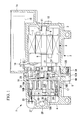
- FIG. 1 shows a longitudinal cross-sectional view of a scroll compressor according to the first embodiment of the present invention
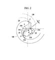
- Fig. 2 is a diagram showing the engagement of scrolls around its discharge port.
- a scroll compressor 1 is equipped with a cylindrical housing 2 that constitutes the outer shell thereof.
- the housing 2 is composed of a motor housing 3 and a compressor housing 4, which are made of die-cast aluminum and are each formed in a bowl shape.
- the motor housing 3 and the compressor housing 4 are configured such that flanges 3A and 4A provided at a plurality of locations around the openings are joined together with bolts 5, with flanges 12A of a bearing member 12, described later, sandwiched therebetween.
- the compressor housing 4 accommodates a scroll compression mechanism 17 constituted by a fixed scroll 18 and a rotating scroll 19.
- the fixed scroll 18 is configured such that a spiral wrap 18B is provided upright on an end plate 18A and is securely fixed in the compressor housing 4 with a bolt 20.
- the rotating scroll 19 is configured such that a spiral wrap 19B is provided upright on an end plate 19A and is disposed so as to be orbitally driven around the fixed scroll 18 because a boss 19C provided at the back of the end plate 19A is coupled with the crankpin 9A of the crankshaft 9 via a drive bush 21 and a rotating bearing 22.
- the pair of compression chambers 24 is configured to perform a compressing operation by continuously repeating the operation wherein, the compression chambers 24 formed at the outermost peripheral positions of the fixed and rotating scrolls 18 and 19 when an intake is shut off are moved to the center while being decreased in volume as the rotating scroll 19 is orbitally driven and wherein the engagement of the fixed and rotating scrolls 18 and 19 is released at the center, so that they join to form one central compression chamber 24A.
- the fluid compressed in the compression chambers 24 is discharged to a discharge chamber 27 through a discharge port 25 provided at the central part of the fixed scroll 18 via a discharge valve 26 and is discharged outwards through a discharge opening 28 provided in the compressor housing 4.
- the discharge port 25 is provided at a position where the outer wall of the spiral wrap 19B of the rotating scroll 19 crosses the discharge port 25 at a point corresponding to a wrap winding start angle of the spiral wraps 18B and 19B of the fixed scroll 18 and the rotating scroll 19, that is, a point ⁇ corresponding to an involute angle, which is an angle to one involute point on an involute curve with the base point on the base circle of the involute curve defined as the starting position, causing the discharge port 25 to communicate with the next compression chamber 24 on the outer side of the central compression chamber 24A, at a timing delayed from the timing at which the spiral wrap 18B or 19B of one scroll is separated from the inner wall of the spiral wrap 18B or 19B of the other scroll (comes into contact at the involute angle ⁇ ), causing the central compression chamber 24A to communicate with the next compression chamber 24 on the outer side thereof.
- Fig. 2 shows a state directly before the spiral wrap 19B of the rotating scroll 19 crosses the discharge port 25 after the engagement at the point
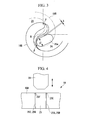
- the oval discharge port 25a has a limitation to the distance S from the very small R due to the straight lines connecting the arcs at both ends; however, with the discharge port 25 having a constriction, the distance S is determined by the constriction, and hence the discharge port 25 can be disposed closer to the spiral wrap 18B by a corresponding distance.
- the deformed-elongated-hole-shaped discharge port 25 can easily be machined in such a manner that, after the circular holes 25A and 25B at both ends are bored by drilling, an end mill having a diameter smaller than the hole diameter D of one of the circular holes 25A and 25B and corresponding to the width W between the two surfaces 25C and 25D is inserted into said one circular hole 25A or 25B, and the end mill is moved toward the other circular hole 25A or 25B to machine the two surfaces 25C and 25D by end-milling.
- burrs between the two surfaces 25C and 25D and the circular hole 25A or 25B are removed using the end mill continuously in a series of continuous operations following the movement of the end mill when the two surfaces 25C and 25D are machined, and thus the deburring is simplified.
- chamfering is performed using a chamfering tool 29, as shown in Fig. 4 .
- a chamfering tool 29 Merely by changing the insertion depth of the chamfering tool 29 in the direction of the arrows between the case where the edges of the circular holes 25A and 25B at both ends are chamfered and the case where the edges of the two surfaces 25C and 25D are chamfered, desired chamfering can easily be performed.
- the chamfering is performed as follows: first, the chamfer 25E is formed around one of the circular holes 25A and 25B at both ends by inserting the chamfering tool 29 in the direction of the arrow by a predetermined amount, with it centered at one of the circular holes 25A and 25B, then, the chamfer 25F is formed along the edges of the two surfaces 25C and 25D while moving the chamfering tool 29 in the direction of the two surfaces 25C and 25D with the insertion depth of the chamfering tool 29 reduced by a predetermined distance, and thereafter, the chamfer 25E can be formed around the other one of the circular holes 25A and 25B at both ends by inserting the chamfering tool 29 again by a predetermined amount, with it centered on the other circular hole.
- this embodiment provides the following advantageous effects.
- fluid (refrigerant gas) taken into the motor housing 3 flows in the housing 2 and is taken into the pair of compression chambers 24 of the scroll compression mechanism 17, where it is compressed when the compression chambers 24 are moved toward the center while being reduced in volume as the rotating scroll 19 is orbitally driven.
- the pair of compression chambers 24 is joined with the central compression chamber 24A when the engagement of the fixed scroll 18 and the rotating scroll 19 is released when the engaging point of the fixed scroll 18 and the rotating scroll 19 passes through the point ⁇ corresponding to the wrap winding start angle of the spiral wraps 18B and 19B.
- the state in Fig. 2 shows a state directly before the outer wall of the spiral wrap 19B of the rotating scroll 19 crosses the discharge port 25, and when the rotation of the rotating scroll 19 advances further, causing the compression chambers 24 and the discharge port 25 to communicate with each other, and a second backflow is generated from the discharge port 25 and the central compression chamber 24A toward the compression chambers 24.
- the second backflow and the first backflow described above, differ in timing; after the first backflow is generated, the second backflow is generated after a delay corresponding to a predetermined rotation angle.
- the deformed-elongated-hole-shaped discharge port 25 in which the circular holes 25A and 25B are provided at both ends and in which the circular holes 25A and 25B at both ends are connected by the two surfaces 25C and 25D whose width W is smaller than the hole diameters D of the circular holes is provided closer to the inner end of the spiral wrap 18B of the fixed scroll 18 and closer to the spiral wrap 18B, the onset of the second backflow of the compressed fluid, which is generated when the outer wall of the spiral wrap 19B of the rotating scroll 19 crosses the discharge port 25, causing the next compression chamber 24 on the outer side of the central compression chamber 24A to communicate with the discharge port 25, is delayed relative to the first backflow of the compressed fluid, which is generated when the engagement of the fixed scroll 18 and the rotating scroll 19 is released, causing the central compression chamber 24A and the next compression chamber 24 on the outer side thereof to communicate with each other, thereby shifting the timings, while ensuring a sufficient cross-sectional area of the flow channel of the discharge port 25.
- the deformed-elongated-hole-shaped discharge port 25 can easily be machined by drilling the circular holes 25A and 25B at both ends and then inserting an end mill having a diameter corresponding to the width W between the two surfaces 25C and 25D smaller than the hole diameter D of one of the circular holes 25A and 25B into one of the circular holes 25A and 25B and machining the two surfaces 25C and 25D by end-milling, a bottleneck in machining can be eliminated.
- the circular holes 25A and 25B at both ends have the same diameter, and since the width W between the two surfaces 25C and 25D therebetween is set smaller than the hole diameters D of the circular holes 25A and 25B at both ends, the circular holes 25A and 25B at both ends can be machined with a drill having the same diameter, and thereafter, an end mill is inserted into one of the circular holes 25A and 25B, and the two surfaces 25C and 25D can be machined by end-milling. Accordingly, this can rationalize and simplify machining of the deformed-elongated-hole-shaped discharge port 25, which reduces the machining time, thus eliminating the bottleneck in machining.
- the deformed-elongated-hole-shaped discharge port 25 is machined in such a manner that, after the circular holes 25A and 25B at both ends are machined by drilling, and an end mill having a diameter smaller than the hole diameter D of one of the circular holes 25A and 25B and corresponding to the width W between the two surfaces 25C and 25D is inserted into this one circular hole 25A or 25B, and the end mill is moved toward the other circular hole to machine the two surfaces 25C and 25D by end-milling. Therefore, the deformed-elongated-hole-shaped discharge port 25 can be formed simply and in a short time at the central portion of the fixed scroll 18 by the combination of drilling and end-milling. Thus, the deformed-elongated-hole-shaped discharge port 25, which is closely analogous to an oval shape and has been difficult to machine, can be provided in the fixed scroll 18, thereby reducing noise.
- the edges of the circular holes 25A and 25B at both ends are chamfered by inserting the chamfering tool 29 into the circular holes 25A and 25B at both ends from the end face of the discharge port 25 by a predetermined amount, and the two surfaces 25C and 25D are chamfered with the insertion depth of the chamfering tool 29 set to be smaller than that during chamfering of the circular holes 25A and 25B.
- the edges of the circular holes 25A and 25B at both ends of the discharge port 25, which are connected by the two surfaces 25C and 25D whose width W is smaller than the hole diameters D of the circular holes 25A and 25B at both ends, and the edges of the two surfaces 25C and 25D can be provided with the proper chamfers 25E and 25F, respectively, by adjusting the insertion depth of the chamfering tool 29. Accordingly, chamfering of the edge of the discharge port 25 can also be simplified, and the production efficiency of the fixed scroll 18 can be improved.
- a second embodiment of the present invention will be described using Fig. 5 .
- This embodiment differs from the foregoing first embodiment in the configuration of a discharge port 35. Since the other features are the same as those of the first embodiment, descriptions thereof will be omitted.
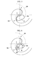
- the discharge port 35 is formed in a deformed elongated hole shape in which a plurality of circular holes 35A are continuously provided so as to partly overlap, as shown in Fig. 5 .
- the pressure fluctuations in compressed fluid remaining in the central compression chamber 24A including the discharge port 25 can be reduced by delaying the onset of the backflow of the compressed fluid that is generated when the outer wall of the spiral wrap 19B of the rotating scroll 19 crosses the discharge port 35, causing the next compression chamber 24 on the outer side of the central compression chamber 24A to communicate with the discharge port 35, relative to the backflow of the compressed fluid that is generated when the engagement of the fixed scroll 18 and the rotating scroll 19 is released, causing the central compression chamber 24A and the next compression chamber 24 on the outer side to communicate with each other, thereby shifting the timings, while ensuring a sufficient cross-sectional area of the flow channel of the discharge port 35.
- this can reduce noise due to pressure waves generated due to the backflow of the compressed fluid, as in the first embodiment. Furthermore, since the deformed-elongated-hole-shaped discharge port 35 can easily be machined by continuously forming, by drilling, the plurality of circular holes 35A so as to partly overlap, the bottleneck in machining can be eliminated, and the practical value can be improved.
- the discharge port 45 is formed in a deformed elongated hole shape in which a circular hole 45A having a large diameter D1 and an ellipse 45B having a hole diameter D2 smaller than that of the circular hole 45A are connected, as shown in Fig. 6 .
- the pressure fluctuations in compressed fluid remaining in the central compression chamber 24A including the discharge port 45 can be reduced by delaying the onset of the backflow of the compressed fluid that is generated when the outer wall of the spiral wrap 19B of the rotating scroll 19 crosses the discharge port 45, causing the next compression chamber 24 on the outer side of the central compression chamber 24A to communicate with the discharge port 45, relative to the backflow of the compressed fluid that is generated when the engagement of the fixed scroll 18 and the rotating scroll 19 is released, causing the central compression chamber 24A and the next compression chamber 24 on the outer side thereof to communicate with each other, thus shifting the timings, while ensuring a sufficient cross-sectional area of the flow channel of the discharge port 45, as in the first and second embodiments.
- this embodiment can also reduce noise due to pressure waves generated due to the backflow of the compressed fluid. Furthermore, since the deformed-elongated-hole-shaped discharge port 45 can easily be machined by drilling the circular hole 45A having the large diameter D1, inserting an end mill having a diameter corresponding to the ellipse 45B having a diameter smaller than the hole diameter D1 into the circular hole 45A, and machining the ellipse 45B connecting to circular hole 45A by end-milling, the bottleneck in machining can be eliminated, and the practical value can be improved.
- the present invention is not limited to the invention according to the foregoing embodiments; various modifications can be made as appropriate without departing from the spirit thereof.
- the embodiments show the respective spiral wraps 18B and 19B of the fixed scroll 18 and the rotating scroll 19 whose wrap thicknesses are changed in two steps in the heightwise direction only at the inner peripheral end (see Fig. 1 )
- the present invention is not limited thereto, and it is needless to say that the present invention can also be applied to a normal scroll compressor, a stepped scroll compressor whose wrap heights differ at the inner peripheral side and the outer peripheral side, and so on.
- the present invention can also be applied to an open-type scroll compressor that accommodates no driving source.
- the area of the discharge port 25 is reduced relative to the oval discharge port 25a of the comparative example shown in Fig. 3 by an area corresponding to the constriction, it has been confirmed that there is almost no difference in performance.
- the lengthwise dimension of the discharge port 25 may be increased by a distance corresponding to the area of the constriction to provide the same area.
Landscapes
- Engineering & Computer Science (AREA)
- Mechanical Engineering (AREA)
- General Engineering & Computer Science (AREA)
- Rotary Pumps (AREA)
- Applications Or Details Of Rotary Compressors (AREA)
Abstract
Description
- The present invention relates to a scroll compressor in which a discharge port that discharges compressed fluid from a compression chamber is provided at the central portion of a fixed scroll and to a method for machining the discharge port.
- A scroll compressor is equipped with a paired fixed scroll and rotating scroll each having a spiral wrap provided upright on an end plate and is configured to compress fluid by causing a compression chamber, formed by engaging the scrolls, to move from its peripheral position toward the center while reducing in volume with the orbital rotary motion of the rotating scroll and to discharge the compressed fluid outwards through a discharge port provided at the central portion of the fixed scroll.
- Such a scroll compressor is configured such that the compression chamber is reduced in volume while being sequentially moved to the center as the rotating scroll is rotationally driven and has a design volume ratio (compression ratio) defined by the ratio of the maximum volume of the compression chamber formed at the outermost peripheral positions of the scrolls when an intake is shut off to the minimum volume of the compression chamber directly before the engagement between the fixed scroll and the rotating scroll is released. A larger design volume ratio is efficient because it decreases the loss, and moreover, it is advantageous in terms of noise.
- To increase the design volume ratio, normally, the technique of increasing the number of windings of the spiral wraps of the fixed scroll and the rotating scroll or the technique of using stepped scrolls in which the spiral wraps are high at the outer peripheral side and low at the inner peripheral side is used. In addition, as disclosed in
PTLs 1 and 2, the technique of decreasing the minimum volume of the compression chamber as much as possible by decreasing the diameter of the discharge port, by forming the discharge port in an oval shape, or by forming the discharge port in a polygonal shape is sometimes employed. -
- {PTL 1} Publication of Japanese Patent No.
3629836 - {PTL 2} Japanese Unexamined Patent Application, Publication No.
2002-242863 - By decreasing the diameter of the discharge port or by forming the discharge port in an oval shape or a polygonal shape, as described above, the onset of backflow of the compressed fluid that is generated when the outer wall of the spiral wrap of the rotating scroll crosses the discharge port, causing the next compression chamber on the outer side of the central compression chamber to communicate with the discharge port, is delayed relative to the backflow of the compressed fluid that occurs when the engagement between the fixed scroll and the rotating scroll is released, causing the central compression chamber and the next compression chamber on the outer side thereof to communicate with each other, and thus the timings can be shifted. This can reduce pressure fluctuations in the compressed fluid remaining in the central compression chamber including the discharge port, thus reducing noise due to the pressure waves thereof. However, these techniques have the following problems.
- The technique of decreasing the diameter of the discharge port has a problem in that the cross-sectional area of the flow channel of the discharge port is decreased, which increases the pressure loss, thus causing an increase in input power. The technique of forming the discharge port in an oval shape inevitably involves more time for machining the discharge port by end-milling although a sufficient cross-sectional area of the channel can be provided, thus decreasing the production efficiency, and hence it is very difficult to put it into practical use. Furthermore, the technique of forming the discharge port in a polygonal shape is difficult to be put into practical use because milling thereof is practically impossible.
- The present invention is made in consideration of such circumstances, and an object thereof is to provide a scroll compressor in which the shape of a discharge port thereof is changed so that noise due to pressure fluctuations in compressed fluid remaining in a central compression chamber including the discharge port can be reduced and machining thereof can be simplified, and a method for machining the discharge port.
- To solve the problems described above, a scroll compressor and a method for machining a discharge port thereof according to the present invention adopt the following solutions.
A scroll compressor according to a first aspect of the present invention is a scroll compressor in which a paired fixed scroll and rotating scroll each having a spiral wrap provided upright on an end plate are engaged to form a compression chamber and in which a discharge port that discharges fluid compressed in the compression chamber is provided at the central portion of the fixed scroll, wherein the discharge port has a deformed elongated hole shape having circular holes at both ends, and the circular holes at both ends are connected by two surfaces the width between which is smaller than the hole diameters of the circular holes. - According to the first aspect of the present invention, since the discharge port has a deformed elongated hole shape in which circular holes are provided at both ends, and the circular holes at both ends are connected by two surfaces the width between which is smaller than the hole diameters of the circular holes, pressure fluctuations in the compressed fluid remaining in the central compression chamber including the discharge port can be reduced by delaying the onset of the backflow of the compressed fluid that is generated when the outer wall of the spiral wrap of the rotating scroll crosses the discharge port, causing the next compression chamber on the outer side of the central compression chamber to communicate with the discharge port, relative to the backflow of the compressed fluid that is generated when the engagement of the fixed scroll and the rotating scroll is released, causing the central compression chamber and the next compression chamber on the outer side thereof to communicate with each other, thereby shifting the timings, while ensuring a sufficient cross-sectional area of the flow channel of the discharge port. Accordingly, this can reduce noise due to pressure waves generated due to the backflow of the compressed fluid. Since the deformed-elongated-hole-shaped discharge port can easily be machined by drilling the circular holes at both ends and then inserting an end mill having a diameter corresponding to the width between the two surfaces which is smaller than the hole diameter of one of the circular holes into said one circular hole and machining the two surfaces by end-milling, a bottleneck in machining can be eliminated, and thus, its practical value can be improved.
- In the scroll compressor of the first aspect of the present invention, preferably, the circular holes at both ends have the same diameter, and the width between the two surfaces therebetween is set to be smaller than the hole diameters of the circular holes at both ends.
- With this configuration, since the circular holes at both ends have the same diameter, and the width between the two surfaces therebetween is set smaller than the hole diameters of the circular holes at both ends, the circular holes at both ends can be machined with a drill having the same diameter, and thereafter, an end mill is inserted into one of the circular holes, and the two surfaces can be machined by end-milling. Accordingly, this can rationalize and simplify machining of the deformed-elongated-hole-shaped discharge port, which reduces the machining time, thus eliminating the bottleneck in machining.
- Furthermore, in the scroll compressor of the first aspect of the present invention, preferably, the discharge port is provided closer to the spiral wrap by a distance corresponding to a constriction of the two surfaces the width between which is set to be smaller than the hole diameters of the circular holes at both ends.
- With this configuration, since the discharge port is provided closer to the spiral wrap by a distance corresponding to the constriction of the two surfaces the width between which is set to be smaller than the hole diameters of the circular holes at both ends, the timing at which the outer wall of the spiral wrap of the rotating scroll crosses the discharge port, causing the next compression chamber on the outer side of the central compression chamber to communicate with the discharge port, can be further delayed as compared with the oval discharge port having the same flow channel cross-sectional area. Accordingly, this can reduce noise due to the backflow of the compressed fluid.
- A scroll compressor according to a second aspect of the present invention is a scroll compressor in which a paired fixed scroll and rotating scroll each having a spiral wrap provided upright on an end plate are engaged to form a compression chamber and in which a discharge port that discharges fluid compressed in the compression chamber is provided at the central portion of the fixed scroll, wherein the discharge port has a deformed elongated hole shape in which a plurality of circular holes are continuously provided so as to partly overlap.
- According to the second aspect of the present invention, since the discharge port has a deformed elongated hole shape in which a plurality of circular holes are continuously provided so as to partly overlap, the pressure fluctuations in compressed fluid remaining in the central compression chamber including the discharge port can be reduced by delaying the onset of the backflow of the compressed fluid that is generated when the outer wall of the spiral wrap of the rotating scroll crosses the discharge port, causing the next compression chamber on the outer side of the central compression chamber to communicate with the discharge port, relative to the backflow of the compressed fluid that is generated when the engagement of the fixed scroll and the rotating scroll is released, causing the central compression chamber and the next compression chamber on the outer side thereof to communicate with each other, thereby shifting the timings, while ensuring a sufficient cross-sectional area of the flow channel of the discharge port. Accordingly, this can reduce noise due to pressure waves generated due to the backflow of the compressed fluid. Furthermore, since the deformed-elongated-hole-shaped discharge port can easily be machined by continuously forming the plurality of circular holes by drilling so as to partly overlap, the bottleneck in machining can be eliminated, and the practical value can be improved.
- A scroll compressor according to a third aspect of the present invention is a scroll compressor in which a paired fixed scroll and rotating scroll each having a spiral wrap provided upright on an end plate are engaged to form a compression chamber and in which a discharge port that discharges fluid compressed in the compression chamber is provided at the central portion of the fixed scroll, wherein the discharge port has a deformed elongated hole shape in which a circular hole having a large diameter and an ellipse having a hole diameter smaller than that of the circular hole are connected.
- According to the third aspect of the present invention, since the discharge port has a deformed elongated hole shape in which a circular hole having a large diameter and an ellipse having a hole diameter smaller than that of the circular hole are connected, pressure fluctuations in compressed fluid remaining in the central compression chamber including the discharge port can be reduced by delaying the onset of the backflow of the compressed fluid that is generated when the outer wall of the spiral wrap of the rotating scroll crosses the discharge port, causing the next compression chamber on the outer side of the central compression chamber to communicate with the discharge port, relative to the backflow of the compressed fluid that is generated when the engagement of the fixed scroll and the rotating scroll is released, causing the central compression chamber and the next compression chamber on the outer side thereof to communicate with each other, thus shifting the timings, while ensuring a sufficient cross-sectional area of the flow channel of the discharge port. Accordingly, this can reduce noise due to pressure waves generated due to the backflow of the compressed fluid. Furthermore, since the deformed-elongated-hole-shaped discharge port can easily be machined by drilling the circular hole having the large diameter, inserting an end mill having a diameter corresponding to the ellipse having a diameter smaller than the hole diameter into the circular hole, and machining the ellipse connecting to the circular hole by end-milling, the bottleneck in machining can be eliminated, and the practical value can be improved.
- In the scroll compressor of the first to third aspects of the present invention, preferably, the discharge port is provided at a position where the outer wall of the spiral wrap of the rotating scroll crosses the discharge port at a point corresponding to a wrap winding start angle of the spiral wraps of the fixed scroll and the rotating scroll, causing the discharge port to communicate with the next compression chamber on the outer side of the central compression chamber, at a timing delayed from the timing at which the spiral wrap of one scroll is separated from the inner wall of the spiral wrap of the other scroll, causing the central compression chamber to communicate with the next compression chamber on the outer side thereof.
- With this configuration, since the discharge port is provided at a position where the outer wall of the spiral wrap of the rotating scroll crosses the discharge port at a point corresponding to a wrap winding start angle of the spiral wraps of the fixed scroll and the rotating scroll, causing the discharge port to communicate with the next compression chamber on the outer side of the central compression chamber, at a timing delayed from the timing at which the spiral wrap of one scroll is separated from the inner wall of the spiral wrap of the other scroll, causing the central compression chamber to communicate with the next compression chamber on the outer side thereof, the next compression chamber on the outer side of the central compression chamber can be made to communicate with the discharge port at a timing delayed from the timing at which the mutual engagement of the fixed scroll and the rotating scroll is released in the compression process, thus causing the central compression chamber and the next compression chamber on the outer side thereof to communicate with each other. Accordingly, this can reliably reduce pressure fluctuations in compressed fluid remaining in the central compression chamber including the discharge port, thus reducing noise due to the backflow of the compressed fluid.
- A method for machining a discharge port of a scroll compressor according to a fourth aspect of the present invention is a method for machining the discharge port of the scroll compressor according to the first to third aspects of the present invention, wherein the deformed-elongated-hole-shaped discharge port is machined by drilling the circular holes at both ends, inserting an end mill having a diameter smaller than the hole diameter of one of the circular holes and corresponding to the width between the two surfaces into said one circular hole, and moving the end mill toward the other circular hole to machine the two surface by end-milling.
- According to the fourth aspect of the present invention, the deformed-elongated-hole-shaped discharge port having circular holes at both ends, in which the circular holes at both ends are connected by the two surfaces the width between which is smaller than the hole diameters of the circular holes, is machined in such a manner that, after the circular holes at both ends are machined by drilling, and an end mill having a diameter smaller than the hole diameter of one of the circular holes and corresponding to the width between the two surfaces is inserted into said one circular hole, and the end mill is moved toward the other circular hole to machine the two surfaces by end-milling; therefore, the deformed-elongated-hole-shaped discharge port can be formed simply and in a short time at the central portion of the fixed scroll by the combination of drilling and end-milling. Thus, providing the deformed-elongated-hole-shaped discharge port, which is closely analogous to an oval shape that has been difficult to machine, in the fixed scroll can reduce noise.
- In the method for machining the discharge port of the scroll compressor according to the fourth aspect of the present invention, preferably, burrs between the two surfaces and the circular holes are removed by machining the two surfaces by end-milling and thereafter moving the end mill along the inner circumference of the other circular hole.
- With this configuration, since burrs between the two surfaces and the circular holes are removed by machining the two surfaces with the end mill and thereafter moving the end mill along the inner circumference of the other circular hole, the burrs between the two surfaces and the circular holes can be removed at the same time by using the end mill continuously in a series of continuous operations following the movement of the end mill during the machining of the two surfaces. Accordingly, this can simplify the deburring and improve the production efficiency of the fixed scroll.
- In the method for machining the discharge port of the scroll compressor according to the fourth aspect of the present invention, preferably, the circular holes at both ends are chamfered by inserting a chamfering tool from one end face of the discharge port into the circular holes at both ends by a predetermined amount, and the two surfaces are chamfered with the insertion depth of the chamfering tool set to be smaller than that during chamfering of the circular holes at both ends.
- With this configuration, the circular holes at both ends are chamfered by inserting the chamfering tool into the circular holes at both ends from the end face of the discharge port by a predetermined amount, and the two surfaces are chamfered with the insertion depth of the chamfering tool set to be smaller than that during chamfering of the circular holes. Therefore, the circular holes at both ends and the two surfaces around the edge of the deformed-elongated-hole-shaped discharge port, in which the circular holes at both ends are connected by the two surfaces the width between which is smaller than the hole diameters of the circular holes at both ends, can individually be provided with proper chamfers by adjusting the insertion depth of the chamfering tool. Accordingly, the chamfering of the edge of the discharge port can also be simplified, and the production efficiency of the fixed scroll can be improved. It is desirable that the chamfer along the two surfaces be as small as possible because increasing the chamfer of the two surfaces will lose the effect achieved by the constriction of the two surfaces.
- In the method for machining the discharge port of the scroll compressor according to the fourth aspect of the present invention, preferably, after one of the circular holes at both ends is chamfered with the chamfering tool, the two surfaces are chamfered with the insertion depth of the chamfering tool changed, and thereafter, the other circular hole is chamfered with the insertion depth of the chamfering tool changed.
- With this configuration, after one of the circular holes at both ends is chamfered using the chamfering tool, the two surfaces are chamfered with the insertion depth of the chamfering tool changed, and thereafter, the other circular hole is chamfered with the insertion depth of the chamfering tool changed; therefore, a series of chamfering operations can be performed in one process by moving the chamfering tool along the lengthwise direction of the deformed-elongated-hole-shaped discharge port and by changing the insertion depth between the positions of the circular holes at both ends. Thus, this can further simplify the chamfering of the edge of the discharge port, thus improving the production efficiency of the fixed scroll.
- According to the scroll compressor of the present invention, since pressure fluctuations in compressed fluid remaining in the central compression chamber including the discharge port can be reduced by delaying the onset of the backflow of the compressed fluid that is generated when the outer wall of the spiral wrap of the rotating scroll crosses the discharge port, causing the next compression chamber on the outer side of the central compression chamber to communicate with the discharge port, relative to the backflow of the compressed fluid that is generated when the engagement of the fixed scroll and the rotating scroll is released, causing the central compression chamber and the next compression chamber on the outer side thereof to communicate with each other, thus shifting the timings, while ensuring a sufficient cross-sectional area of the flow channel of the discharge port, noise due to pressure waves generated due to the backflow of the compressed fluid can be reduced. Since the deformed-elongated-hole-shaped discharge port can easily be machined by drilling the circular holes at both ends and then inserting an end mill having a diameter corresponding to the width between the two surfaces which is smaller than the hole diameter of one of the circular holes into one of the circular holes and machining the two surfaces by end-milling, a bottleneck in machining can be eliminated, and thus, its practical value can be improved.
- According to the scroll compressor of the present invention, since the deformed-elongated-hole-shaped discharge port in which a plurality of circular holes are continuously provided so as to partly overlap can easily be machined by continuously forming the plurality of circular holes by drilling so as to partly overlap, the bottleneck in machining can be eliminated, and the practical value can be improved.
Furthermore, according to the scroll compressor of the present invention, since the deformed-elongated-hole-shaped discharge port in which a circular hole having a large diameter and an ellipse having a hole diameter smaller than that of the circular hole are connected can easily be machined by drilling the circular hole having the large diameter, inserting an end mill having a diameter corresponding to the ellipse having a diameter smaller than the hole diameter into the circular hole, and machining the ellipse connecting to circular hole by end-milling, the bottleneck in machining can be eliminated, and the practical value can be improved. - According to the method for machining the discharge port of the scroll compressor of the present invention, since the deformed-elongated-hole-shaped discharge port can be formed simply and in a short time at the central portion of the fixed scroll by the combination of drilling and end-milling, providing the deformed-elongated-hole-shaped discharge port, which is closely analogous to an oval shape that has been difficult to machine, in the fixed scroll can reduce noise.
-
- {
Fig. 1} Fig. 1 is a longitudinal cross-sectional view of a scroll compressor according to a first embodiment of the present invention. - {
Fig. 2} Fig. 2 is a diagram showing the engagement of scrolls around a discharge port in the scroll compressor shown inFig. 1 . - {
Fig. 3} Fig. 3 is a diagram showing the engagement of scrolls around a discharge port of a comparative example related to the discharge port shown inFig. 2 . - {
Fig. 4} Fig. 4 is an explanatory diagram of a method for chamfering the edge of the discharge port of the scroll compressor shown inFig. 1 . - {
Fig. 5} Fig. 5 is a diagram showing the engagement of scrolls around a discharge port in a scroll compressor according to a second embodiment of the present invention. - {
Fig. 6} Fig. 6 is a diagram showing the engagement of scrolls around a discharge port in a scroll compressor according to a third embodiment of the present invention. - Embodiments according to the present invention will be described hereinbelow with reference to the drawings.
- A first embodiment of the present invention will be described hereinbelow using
Figs. 1 to 4 .
Fig. 1 shows a longitudinal cross-sectional view of a scroll compressor according to the first embodiment of the present invention, andFig. 2 is a diagram showing the engagement of scrolls around its discharge port.
A scroll compressor 1 is equipped with acylindrical housing 2 that constitutes the outer shell thereof. Thehousing 2 is composed of amotor housing 3 and acompressor housing 4, which are made of die-cast aluminum and are each formed in a bowl shape. Themotor housing 3 and thecompressor housing 4 are configured such thatflanges bolts 5, withflanges 12A of a bearingmember 12, described later, sandwiched therebetween. - The
motor housing 3 accommodates amotor 8 constituted by arotor 6 and astator 7, and acrankshaft 9 is integrally joined with therotor 6. The rear end of thecrankshaft 9 is rotatably supported by a bearingportion 10 provided on the rear end wall of themotor housing 3 via abearing 11, and the front end is rotatably supported by the bearingmember 12 disposed between themotor housing 3 and thecompressor housing 4 via abearing 13. The front end of thecrankshaft 9 is integrally provided with acrankpin 9A that is eccentric relative to the axial center by a predetermined distance. - An
inverter accommodating section 14 is integrally formed on the outer periphery of themotor housing 3 and accommodates aninverter 15 that drives themotor 8. Theinverter 15 converts direct-current power supplied from an external power source to a three-phase alternating-current power having a command frequency and applies it to themotor 8 accommodated in themotor housing 3 via a glass-sealedterminal 16. Theinverter 15 may be a known inverter, and a detailed description thereof will be omitted. - The
compressor housing 4 accommodates ascroll compression mechanism 17 constituted by a fixedscroll 18 and arotating scroll 19. The fixedscroll 18 is configured such that aspiral wrap 18B is provided upright on anend plate 18A and is securely fixed in thecompressor housing 4 with abolt 20. Therotating scroll 19 is configured such that aspiral wrap 19B is provided upright on anend plate 19A and is disposed so as to be orbitally driven around the fixedscroll 18 because a boss 19C provided at the back of theend plate 19A is coupled with thecrankpin 9A of thecrankshaft 9 via adrive bush 21 and a rotatingbearing 22. - The
rotating scroll 19 is disposed such that the back surface of theend plate 19A is supported by athrust bearing portion 12B of the bearingmember 12 and such that the rotation thereof is prevented by arotation prevention mechanism 23, such as an Oldham's ring, disposed between thethrust bearing portion 12B and the back surface of theend plate 19A. As is well known, the fixedscroll 18 and therotating scroll 19 are configured such that the spiral wraps 18B and 19B are opposed and engaged 180° out of phases with each other so that a pair ofcompression chambers 24 is formed. - The pair of
compression chambers 24 is configured to perform a compressing operation by continuously repeating the operation wherein, thecompression chambers 24 formed at the outermost peripheral positions of the fixed androtating scrolls rotating scroll 19 is orbitally driven and wherein the engagement of the fixed androtating scrolls central compression chamber 24A. The fluid compressed in thecompression chambers 24 is discharged to adischarge chamber 27 through adischarge port 25 provided at the central part of the fixedscroll 18 via adischarge valve 26 and is discharged outwards through adischarge opening 28 provided in thecompressor housing 4. - In this embodiment, as shown in
Fig. 2 , thedischarge port 25 has a deformed elongated hole shape havingcircular holes circular holes surfaces circular holes circular holes discharge port 25 are set at the same diameter, for example, 5 mm, while the width W between the twosurfaces - The
discharge port 25 is provided at a position where the outer wall of thespiral wrap 19B of therotating scroll 19 crosses thedischarge port 25 at a point corresponding to a wrap winding start angle of the spiral wraps 18B and 19B of the fixedscroll 18 and therotating scroll 19, that is, a point β corresponding to an involute angle, which is an angle to one involute point on an involute curve with the base point on the base circle of the involute curve defined as the starting position, causing thedischarge port 25 to communicate with thenext compression chamber 24 on the outer side of thecentral compression chamber 24A, at a timing delayed from the timing at which thespiral wrap spiral wrap central compression chamber 24A to communicate with thenext compression chamber 24 on the outer side thereof.Fig. 2 shows a state directly before thespiral wrap 19B of therotating scroll 19 crosses thedischarge port 25 after the engagement at the point β is released, causing thedischarge port 25 to communicate with thenext compression chamber 24 on the outer side of thecentral compression chamber 24A. - The
discharge port 25 is shaped such that the width W between the twosurfaces circular holes spiral wrap 18B by a distance corresponding to the constriction relative to anoval discharge port 25a of a comparative example, shown inFig. 3 . That is, in the case where the discharge port is provided a predetermined distance S, for example, 0.3 mm, away from a very small R provided at the base of the spiral wrap 18B to prevent thedischarge port 25 from coming into contact with the very small R, theoval discharge port 25a has a limitation to the distance S from the very small R due to the straight lines connecting the arcs at both ends; however, with thedischarge port 25 having a constriction, the distance S is determined by the constriction, and hence thedischarge port 25 can be disposed closer to thespiral wrap 18B by a corresponding distance. - Furthermore, the deformed-elongated-hole-shaped
discharge port 25 can easily be machined in such a manner that, after thecircular holes circular holes surfaces circular hole circular hole surfaces - When the two
surfaces circular hole surfaces surfaces circular hole surfaces - In addition, it is necessary to chamfer the edge of the
discharge port 25. The chamfering is performed using achamfering tool 29, as shown inFig. 4 . Merely by changing the insertion depth of thechamfering tool 29 in the direction of the arrows between the case where the edges of thecircular holes surfaces circular holes large chamfer 25E can be provided by increasing the insertion depth of thechamfering tool 29, and whenchamfers 25F are to be provided along the peripheries of the twosurfaces small chamfer 25F can be provided by decreasing the insertion depth of thechamfering tool 29. - The chamfering is performed as follows: first, the
chamfer 25E is formed around one of thecircular holes chamfering tool 29 in the direction of the arrow by a predetermined amount, with it centered at one of thecircular holes chamfer 25F is formed along the edges of the twosurfaces chamfering tool 29 in the direction of the twosurfaces chamfering tool 29 reduced by a predetermined distance, and thereafter, thechamfer 25E can be formed around the other one of thecircular holes chamfering tool 29 again by a predetermined amount, with it centered on the other circular hole. - Thus, the desired
chamfers circular holes surfaces chamfer 25F along the twosurfaces chamfer 25F thereof would lose the effect of the constriction of the twosurfaces - Thus, this embodiment provides the following advantageous effects.
In the scroll compressor 1, fluid (refrigerant gas) taken into themotor housing 3 flows in thehousing 2 and is taken into the pair ofcompression chambers 24 of thescroll compression mechanism 17, where it is compressed when thecompression chambers 24 are moved toward the center while being reduced in volume as therotating scroll 19 is orbitally driven. The pair ofcompression chambers 24 is joined with thecentral compression chamber 24A when the engagement of the fixedscroll 18 and therotating scroll 19 is released when the engaging point of the fixedscroll 18 and therotating scroll 19 passes through the point β corresponding to the wrap winding start angle of the spiral wraps 18B and 19B. - When the compressing operation further advances from this state, and the compressed fluid reaches a discharge pressure to push open the
discharge valve 26, the fluid is discharged from thecentral compression chamber 24A to thedischarge chamber 27 through thedischarge port 25. During this operation, when the engaging point of the fixedscroll 18 and therotating scroll 19 passes through the point β, and thecompression chambers 24 are joined with thecentral compression chamber 24A, high-pressure fluid remaining in thecentral compression chamber 24A and thedischarge port 25 generates a first backflow toward the pair ofcompression chambers 24. On the other hand, when the engagement of the fixedscroll 18 and therotating scroll 19 is released at the point β, and the rotation of therotating scroll 19 advances further, the state shown inFig. 2 occurs. - The state in
Fig. 2 shows a state directly before the outer wall of thespiral wrap 19B of therotating scroll 19 crosses thedischarge port 25, and when the rotation of therotating scroll 19 advances further, causing thecompression chambers 24 and thedischarge port 25 to communicate with each other, and a second backflow is generated from thedischarge port 25 and thecentral compression chamber 24A toward thecompression chambers 24. However, the second backflow and the first backflow, described above, differ in timing; after the first backflow is generated, the second backflow is generated after a delay corresponding to a predetermined rotation angle. - That is, since the deformed-elongated-hole-shaped
discharge port 25 in which thecircular holes circular holes surfaces spiral wrap 18B of the fixedscroll 18 and closer to thespiral wrap 18B, the onset of the second backflow of the compressed fluid, which is generated when the outer wall of thespiral wrap 19B of therotating scroll 19 crosses thedischarge port 25, causing thenext compression chamber 24 on the outer side of thecentral compression chamber 24A to communicate with thedischarge port 25, is delayed relative to the first backflow of the compressed fluid, which is generated when the engagement of the fixedscroll 18 and therotating scroll 19 is released, causing thecentral compression chamber 24A and thenext compression chamber 24 on the outer side thereof to communicate with each other, thereby shifting the timings, while ensuring a sufficient cross-sectional area of the flow channel of thedischarge port 25. - This can reduce pressure fluctuations in the compressed fluid remaining in the
central compression chamber 24A including thedischarge port 25, thus reducing noise due to pressure waves generated due to the backflow of the compressed fluid. Since the deformed-elongated-hole-shapeddischarge port 25 can easily be machined by drilling thecircular holes surfaces circular holes circular holes surfaces - In the case of the
oval discharge port 25a shown inFig. 3 as a comparative example, even if the circular holes at both ends can be machined by drilling, in practice, it is difficult to insert an end mill having the same diameter into the holes. Thus, it is necessary to machine the holes so as to dig in from the surface side by a predetermined distance at a time, which increases the machining time, and hence this is not used in practice. However, this embodiment can eliminate such a bottleneck in machining, thus improving its practical value. - In contrast to this
oval discharge port 25a, in the case of the deformed-elongated-hole-shapeddischarge port 25 in which the width W between the twosurfaces circular holes surfaces spiral wrap 18B, thedischarge port 25 can be disposed closer to thespiral wrap 18B. This allows noise due to the backflow of the compressed fluid to be reduced by a corresponding amount as compared with the comparative example shown inFig. 3 . - Since the
circular holes surfaces circular holes circular holes circular holes surfaces discharge port 25, which reduces the machining time, thus eliminating the bottleneck in machining. - Furthermore, in this embodiment, the deformed-elongated-hole-shaped
discharge port 25 is machined in such a manner that, after thecircular holes circular holes surfaces circular hole surfaces discharge port 25 can be formed simply and in a short time at the central portion of the fixedscroll 18 by the combination of drilling and end-milling. Thus, the deformed-elongated-hole-shapeddischarge port 25, which is closely analogous to an oval shape and has been difficult to machine, can be provided in the fixedscroll 18, thereby reducing noise. - When the
discharge port 25 is machined by the foregoing method, burrs between the twosurfaces circular holes surfaces circular hole surfaces circular holes surfaces scroll 18 can be improved. - Furthermore, in this embodiment, when the edge of the
discharge port 25 is to be chamfered, the edges of thecircular holes chamfering tool 29 into thecircular holes discharge port 25 by a predetermined amount, and the twosurfaces chamfering tool 29 set to be smaller than that during chamfering of thecircular holes circular holes discharge port 25, which are connected by the twosurfaces circular holes surfaces proper chamfers chamfering tool 29. Accordingly, chamfering of the edge of thedischarge port 25 can also be simplified, and the production efficiency of the fixedscroll 18 can be improved. - In the chamfering, since, after one of the
circular holes chamfering tool 29, the twosurfaces chamfering tool 29 changed, and thereafter, the other of thecircular holes chamfering tool 29 changed, a series of chamfering operations can be performed in a single process by moving thechamfering tool 29 along the lengthwise direction of the deformed-elongated-hole-shapeddischarge port 25 and by changing the insertion depth between the positions of thecircular holes chamfers discharge port 25, thus improving the production efficiency of the fixedscroll 18. - Next, a second embodiment of the present invention will be described using
Fig. 5 .
This embodiment differs from the foregoing first embodiment in the configuration of adischarge port 35. Since the other features are the same as those of the first embodiment, descriptions thereof will be omitted.
In this embodiment, thedischarge port 35 is formed in a deformed elongated hole shape in which a plurality ofcircular holes 35A are continuously provided so as to partly overlap, as shown inFig. 5 . - As described above, also with the
discharge port 35 having the configuration in which the plurality ofcircular holes 35A are continuously provided so as to partly overlap, the pressure fluctuations in compressed fluid remaining in thecentral compression chamber 24A including thedischarge port 25 can be reduced by delaying the onset of the backflow of the compressed fluid that is generated when the outer wall of thespiral wrap 19B of therotating scroll 19 crosses thedischarge port 35, causing thenext compression chamber 24 on the outer side of thecentral compression chamber 24A to communicate with thedischarge port 35, relative to the backflow of the compressed fluid that is generated when the engagement of the fixedscroll 18 and therotating scroll 19 is released, causing thecentral compression chamber 24A and thenext compression chamber 24 on the outer side to communicate with each other, thereby shifting the timings, while ensuring a sufficient cross-sectional area of the flow channel of thedischarge port 35. - Accordingly, this can reduce noise due to pressure waves generated due to the backflow of the compressed fluid, as in the first embodiment. Furthermore, since the deformed-elongated-hole-shaped
discharge port 35 can easily be machined by continuously forming, by drilling, the plurality ofcircular holes 35A so as to partly overlap, the bottleneck in machining can be eliminated, and the practical value can be improved. - Next, a third embodiment of the present invention will be described using
Fig. 6 .
This embodiment differs from the foregoing first and second embodiments in the configuration of adischarge port 45. Since the other features are the same as those of the first and second embodiments, descriptions thereof will be omitted.
In this embodiment, thedischarge port 45 is formed in a deformed elongated hole shape in which acircular hole 45A having a large diameter D1 and anellipse 45B having a hole diameter D2 smaller than that of thecircular hole 45A are connected, as shown inFig. 6 . - As described above, also with the deformed-elongated-hole-shaped
discharge port 45 in which thecircular hole 45A having the large diameter D1 and theellipse 45B having the hole diameter D2 smaller than that of thecircular hole 45A are connected, the pressure fluctuations in compressed fluid remaining in thecentral compression chamber 24A including thedischarge port 45 can be reduced by delaying the onset of the backflow of the compressed fluid that is generated when the outer wall of thespiral wrap 19B of therotating scroll 19 crosses thedischarge port 45, causing thenext compression chamber 24 on the outer side of thecentral compression chamber 24A to communicate with thedischarge port 45, relative to the backflow of the compressed fluid that is generated when the engagement of the fixedscroll 18 and therotating scroll 19 is released, causing thecentral compression chamber 24A and thenext compression chamber 24 on the outer side thereof to communicate with each other, thus shifting the timings, while ensuring a sufficient cross-sectional area of the flow channel of thedischarge port 45, as in the first and second embodiments. - Accordingly, this embodiment can also reduce noise due to pressure waves generated due to the backflow of the compressed fluid. Furthermore, since the deformed-elongated-hole-shaped
discharge port 45 can easily be machined by drilling thecircular hole 45A having the large diameter D1, inserting an end mill having a diameter corresponding to theellipse 45B having a diameter smaller than the hole diameter D1 into thecircular hole 45A, and machining theellipse 45B connecting tocircular hole 45A by end-milling, the bottleneck in machining can be eliminated, and the practical value can be improved. - The present invention is not limited to the invention according to the foregoing embodiments; various modifications can be made as appropriate without departing from the spirit thereof. For example, although the embodiments show the respective spiral wraps 18B and 19B of the fixed
scroll 18 and therotating scroll 19 whose wrap thicknesses are changed in two steps in the heightwise direction only at the inner peripheral end (seeFig. 1 ), the present invention is not limited thereto, and it is needless to say that the present invention can also be applied to a normal scroll compressor, a stepped scroll compressor whose wrap heights differ at the inner peripheral side and the outer peripheral side, and so on. - Although an example of application to the electric scroll compressor 1 that accommodates the
motor 8 has been described in the foregoing embodiments, it is needless to say that the present invention can also be applied to an open-type scroll compressor that accommodates no driving source. Furthermore, in the foregoing embodiment, although the area of thedischarge port 25 is reduced relative to theoval discharge port 25a of the comparative example shown inFig. 3 by an area corresponding to the constriction, it has been confirmed that there is almost no difference in performance. Of course, the lengthwise dimension of thedischarge port 25 may be increased by a distance corresponding to the area of the constriction to provide the same area. -
- 1
- scroll compressor
- 18
- fixed scroll
- 18A
- end plate
- 18B
- spiral wrap
- 19
- rotating scroll
- 19A
- end plate
- 19B
- spiral wrap
- 24
- compression chamber
- 24A
- central compression chamber
- 25, 35, 45
- discharge port
- 25A, 25B
- circular holes at both ends
- 25C, 25D
- two surfaces
- 25E
- chamfer of circular holes at both ends
- 25F
- chamfer of two surfaces
- 29
- chamfering tool
- 35A
- plurality of circular holes
- 45A
- circular hole
- 45B
- ellipse
- D
- hole diameter of circular holes at both ends
- W
- width between two surfaces
- β
- point corresponding to wrap winding start angle
Claims (10)
- A scroll compressor in which a paired fixed scroll and rotating scroll each having a spiral wrap provided upright on an end plate are engaged to form a compression chamber and in which a discharge port that discharges fluid compressed in the compression chamber is provided at the central portion of the fixed scroll, wherein the discharge port has a deformed elongated hole shape having circular holes at both ends, and the circular holes at both ends are connected by two surfaces the width between which is smaller than the hole diameters of the circular holes.
- The scroll compressor according to Claim 1, wherein the circular holes at both ends have the same diameter, and the width between the two surfaces therebetween is set to be smaller than the hole diameters of the circular holes at both ends.
- The scroll compressor according to Claim 1 or 2, wherein the discharge port is provided closer to the spiral wrap by a distance corresponding to a constriction of the two surfaces the width between which is set to be smaller than the hole diameters of the circular holes at both ends.
- A scroll compressor in which a paired fixed scroll and rotating scroll each having a spiral wrap provided upright on an end plate are engaged to form a compression chamber and in which a discharge port that discharges fluid compressed in the compression chamber is provided at the central portion of the fixed scroll,
wherein the discharge port has a deformed elongated hole shape in which a plurality of circular holes are continuously provided so as to partly overlap. - A scroll compressor in which a paired fixed scroll and rotating scroll each having a spiral wrap provided upright on an end plate are engaged to form a compression chamber and in which a discharge port that discharges fluid compressed in the compression chamber is provided at the central portion of the fixed scroll,
wherein the discharge port has a deformed elongated hole shape in which a circular hole having a large diameter and an ellipse having a hole diameter smaller than that of the circular hole are connected. - The scroll compressor according to any of Claims 1 to 5, wherein the discharge port is provided at a position where the outer wall of the spiral wrap of the rotating scroll crosses the discharge port at a point corresponding to a wrap winding start angle of the spiral wraps of the fixed scroll and the rotating scroll, causing the discharge port to communicate with the next compression chamber on the outer side of the central compression chamber, at a timing delayed from the timing at which the spiral wrap of one scroll is separated from the inner wall of the spiral wrap of the other scroll, causing the central compression chamber to communicate with the next compression chamber on the outer side thereof.
- A method for machining the discharge port of the scroll compressor according to any of Claims 1 to 3 and 6,
wherein the deformed-elongated-hole-shaped discharge port is machined by drilling the circular holes at both ends, inserting an end mill having a diameter smaller than the hole diameter of one of the circular holes and corresponding to the width between the two surfaces into said one circular hole, and moving the end mill toward the other circular hole to machine the two surface by end-milling. - The method for machining the discharge port of the scroll compressor according to Claim 7, wherein burrs between the two surfaces and the circular holes are removed by machining the two surfaces with the end mill and thereafter moving the end mill along the inner circumference of the other circular hole.
- The method for machining the discharge port of the scroll compressor according to Claim 7 or 8, wherein the circular holes at both ends are chamfered by inserting a chamfering tool from one end face of the discharge port into the circular holes at both ends by a predetermined amount, and the two surfaces are chamfered with the insertion depth of the chamfering tool set to be smaller than that during chamfering of the circular holes at both ends.
- The method for machining the discharge port of the scroll compressor according to Claim 9, wherein after one of the circular holes at both ends is chamfered with the chamfering tool, the two surfaces are chamfered with the insertion depth of the chamfering tool changed, and thereafter, the other circular hole is chamfered with the insertion depth of the chamfering tool changed.
Applications Claiming Priority (2)
| Application Number | Priority Date | Filing Date | Title |
|---|---|---|---|
| JP2010128578A JP5461313B2 (en) | 2010-06-04 | 2010-06-04 | Scroll compressor and discharge port machining method thereof |
| PCT/JP2011/061830 WO2011152243A1 (en) | 2010-06-04 | 2011-05-24 | Scroll compressor and method for processing discharge port in same |
Publications (3)
| Publication Number | Publication Date |
|---|---|
| EP2578884A1 true EP2578884A1 (en) | 2013-04-10 |
| EP2578884A4 EP2578884A4 (en) | 2015-01-14 |
| EP2578884B1 EP2578884B1 (en) | 2019-06-26 |
Family
ID=45066621
Family Applications (1)
| Application Number | Title | Priority Date | Filing Date |
|---|---|---|---|
| EP11789652.2A Active EP2578884B1 (en) | 2010-06-04 | 2011-05-24 | Scroll compressor and method for processing discharge port in same |
Country Status (5)
| Country | Link |
|---|---|
| US (1) | US9121406B2 (en) |
| EP (1) | EP2578884B1 (en) |
| JP (1) | JP5461313B2 (en) |
| CN (1) | CN102725531B (en) |
| WO (1) | WO2011152243A1 (en) |
Cited By (1)
| Publication number | Priority date | Publication date | Assignee | Title |
|---|---|---|---|---|
| EP3492745A4 (en) * | 2016-07-29 | 2020-02-26 | Daikin Industries, Ltd. | SPIRAL COMPRESSOR |
Families Citing this family (6)
| Publication number | Priority date | Publication date | Assignee | Title |
|---|---|---|---|---|
| JP2015059536A (en) * | 2013-09-20 | 2015-03-30 | 日立アプライアンス株式会社 | Scroll compressor |
| CN104595184A (en) * | 2014-12-06 | 2015-05-06 | 无锡高卓流体设备有限公司 | Scroll fluid machine |
| US10619635B2 (en) * | 2016-07-21 | 2020-04-14 | Trane International Inc. | Scallop step for a scroll compressor |
| GB2569914B (en) * | 2016-10-28 | 2021-10-20 | Mitsubishi Electric Corp | Scroll compressor, refrigeration cycle apparatus, and shell |
| JP6485500B2 (en) * | 2017-07-07 | 2019-03-20 | ダイキン工業株式会社 | Scroll compressor |
| CN110340695A (en) * | 2019-07-24 | 2019-10-18 | 中国航发贵州黎阳航空动力有限公司 | The fixture of fan groove is processed on milling machine |
Family Cites Families (14)
| Publication number | Priority date | Publication date | Assignee | Title |
|---|---|---|---|---|
| JPS63215892A (en) | 1987-03-02 | 1988-09-08 | Sanyo Electric Co Ltd | Scroll compressor |
| JPS63255585A (en) * | 1987-04-10 | 1988-10-21 | Sanyo Electric Co Ltd | Scroll compressor |
| US4886434A (en) * | 1987-02-20 | 1989-12-12 | Sanyo Electric Co., Ltd. | Scroll compressor having discharge part communicating with two compression spaces simultaneously |
| JPS6463686A (en) * | 1987-09-04 | 1989-03-09 | Hitachi Ltd | Scroll compressor |
| US5242283A (en) * | 1991-03-15 | 1993-09-07 | Kabushiki Kaisha Toyoda Jidoshokki Seisakusho | Scroll type compressor with elongated discharge port |
| JP3036271B2 (en) | 1992-12-03 | 2000-04-24 | 株式会社豊田自動織機製作所 | Scroll compressor |
| JP3629836B2 (en) * | 1996-09-18 | 2005-03-16 | 株式会社日立製作所 | Scroll fluid machinery |
| JP3424506B2 (en) | 1997-06-25 | 2003-07-07 | ダイキン工業株式会社 | Scroll fluid machine |
| US6746224B2 (en) * | 2000-06-22 | 2004-06-08 | Mitsubishi Heavy Industries, Ltd. | Scroll compressor |
| JP2002242863A (en) | 2001-02-20 | 2002-08-28 | Mitsubishi Heavy Ind Ltd | Scroll compressor |
| IL141828A (en) * | 2001-03-05 | 2009-05-04 | Hanita Metal Works Ltd | Multi-purpose end-mill |
| JP2003124645A (en) | 2001-10-11 | 2003-04-25 | Kawamura Electric Inc | Box fixed structure |
| JP4241610B2 (en) * | 2004-12-27 | 2009-03-18 | 株式会社日立産機システム | Vacuum pump |
| JP2009090841A (en) | 2007-10-10 | 2009-04-30 | Toyota Motor Corp | Fuel tank mounting structure |
-
2010
- 2010-06-04 JP JP2010128578A patent/JP5461313B2/en not_active Expired - Fee Related
-
2011
- 2011-05-24 WO PCT/JP2011/061830 patent/WO2011152243A1/en not_active Ceased
- 2011-05-24 CN CN201180007581.6A patent/CN102725531B/en not_active Expired - Fee Related
- 2011-05-24 EP EP11789652.2A patent/EP2578884B1/en active Active
- 2011-05-24 US US13/515,701 patent/US9121406B2/en not_active Expired - Fee Related
Cited By (1)
| Publication number | Priority date | Publication date | Assignee | Title |
|---|---|---|---|---|
| EP3492745A4 (en) * | 2016-07-29 | 2020-02-26 | Daikin Industries, Ltd. | SPIRAL COMPRESSOR |
Also Published As
| Publication number | Publication date |
|---|---|
| JP5461313B2 (en) | 2014-04-02 |
| WO2011152243A1 (en) | 2011-12-08 |
| CN102725531A (en) | 2012-10-10 |
| EP2578884B1 (en) | 2019-06-26 |
| EP2578884A4 (en) | 2015-01-14 |
| US9121406B2 (en) | 2015-09-01 |
| JP2011252479A (en) | 2011-12-15 |
| CN102725531B (en) | 2016-01-06 |
| US20120251369A1 (en) | 2012-10-04 |
Similar Documents
| Publication | Publication Date | Title |
|---|---|---|
| EP2578884B1 (en) | Scroll compressor and method for processing discharge port in same | |
| EP2689137B1 (en) | Scroll compressor | |
| EP2581605B1 (en) | Scroll compressor with bypass hole | |
| EP3553318B1 (en) | Scroll compressor | |
| EP3889432B1 (en) | Rotary compressor | |
| EP2280148B1 (en) | Scroll fluid machine | |
| US20090060767A1 (en) | Axial compliance | |
| EP2264319A2 (en) | Oil free screw compressor | |
| CN109072912B (en) | Stepped scroll compressor and method of designing the same | |
| CN108350880A (en) | scroll compressor | |
| EP2149708A2 (en) | Scroll compressor with bypass ports driven by a line fed permanent magnet sychronous type motor. | |
| US7273363B1 (en) | Scroll compressor with slider block having recess | |
| US11015600B2 (en) | Scroll compressor having sub-discharge port with involute-shaped opening | |
| CN103835946B (en) | Scroll compressor | |
| EP3141754A1 (en) | Rotary compressor and method for manufacturing the same | |
| JP4131561B2 (en) | Scroll compressor | |
| EP4273401B1 (en) | Scroll compressor | |
| EP3617513B1 (en) | Compressor and refrigeration cycle device | |
| EP4239196B1 (en) | Scroll compressor | |
| KR102859738B1 (en) | Scroll compressor | |
| US8939741B2 (en) | Scroll compressor | |
| EP4151858A1 (en) | Screw compressor | |
| WO2022230314A1 (en) | Scroll compressor | |
| JP2000249084A (en) | Scroll compressor | |
| JP2001153071A (en) | Scroll fluid machine |
Legal Events
| Date | Code | Title | Description |
|---|---|---|---|
| PUAI | Public reference made under article 153(3) epc to a published international application that has entered the european phase |
Free format text: ORIGINAL CODE: 0009012 |
|
| 17P | Request for examination filed |
Effective date: 20120611 |
|
| AK | Designated contracting states |
Kind code of ref document: A1 Designated state(s): AL AT BE BG CH CY CZ DE DK EE ES FI FR GB GR HR HU IE IS IT LI LT LU LV MC MK MT NL NO PL PT RO RS SE SI SK SM TR |
|
| DAX | Request for extension of the european patent (deleted) | ||
| A4 | Supplementary search report drawn up and despatched |
Effective date: 20141212 |
|
| RIC1 | Information provided on ipc code assigned before grant |
Ipc: F04C 29/12 20060101ALI20141208BHEP Ipc: F04C 18/02 20060101AFI20141208BHEP Ipc: F04C 29/00 20060101ALI20141208BHEP |
|
| GRAP | Despatch of communication of intention to grant a patent |
Free format text: ORIGINAL CODE: EPIDOSNIGR1 |
|
| STAA | Information on the status of an ep patent application or granted ep patent |
Free format text: STATUS: GRANT OF PATENT IS INTENDED |
|
| RIC1 | Information provided on ipc code assigned before grant |
Ipc: F04C 29/12 20060101ALI20181129BHEP Ipc: F04C 18/02 20060101AFI20181129BHEP Ipc: F04C 29/00 20060101ALI20181129BHEP |
|
| INTG | Intention to grant announced |
Effective date: 20190102 |
|
| GRAS | Grant fee paid |
Free format text: ORIGINAL CODE: EPIDOSNIGR3 |
|
| GRAA | (expected) grant |
Free format text: ORIGINAL CODE: 0009210 |
|
| STAA | Information on the status of an ep patent application or granted ep patent |
Free format text: STATUS: THE PATENT HAS BEEN GRANTED |
|
| AK | Designated contracting states |
Kind code of ref document: B1 Designated state(s): AL AT BE BG CH CY CZ DE DK EE ES FI FR GB GR HR HU IE IS IT LI LT LU LV MC MK MT NL NO PL PT RO RS SE SI SK SM TR |
|
| REG | Reference to a national code |
Ref country code: GB Ref legal event code: FG4D |
|
| REG | Reference to a national code |
Ref country code: CH Ref legal event code: EP |
|
| REG | Reference to a national code |
Ref country code: AT Ref legal event code: REF Ref document number: 1148591 Country of ref document: AT Kind code of ref document: T Effective date: 20190715 |
|
| REG | Reference to a national code |
Ref country code: DE Ref legal event code: R096 Ref document number: 602011060062 Country of ref document: DE |
|
| REG | Reference to a national code |
Ref country code: IE Ref legal event code: FG4D |
|
| REG | Reference to a national code |
Ref country code: NL Ref legal event code: MP Effective date: 20190626 |
|
| PG25 | Lapsed in a contracting state [announced via postgrant information from national office to epo] |
Ref country code: SE Free format text: LAPSE BECAUSE OF FAILURE TO SUBMIT A TRANSLATION OF THE DESCRIPTION OR TO PAY THE FEE WITHIN THE PRESCRIBED TIME-LIMIT Effective date: 20190626 Ref country code: LT Free format text: LAPSE BECAUSE OF FAILURE TO SUBMIT A TRANSLATION OF THE DESCRIPTION OR TO PAY THE FEE WITHIN THE PRESCRIBED TIME-LIMIT Effective date: 20190626 Ref country code: AL Free format text: LAPSE BECAUSE OF FAILURE TO SUBMIT A TRANSLATION OF THE DESCRIPTION OR TO PAY THE FEE WITHIN THE PRESCRIBED TIME-LIMIT Effective date: 20190626 Ref country code: HR Free format text: LAPSE BECAUSE OF FAILURE TO SUBMIT A TRANSLATION OF THE DESCRIPTION OR TO PAY THE FEE WITHIN THE PRESCRIBED TIME-LIMIT Effective date: 20190626 Ref country code: NO Free format text: LAPSE BECAUSE OF FAILURE TO SUBMIT A TRANSLATION OF THE DESCRIPTION OR TO PAY THE FEE WITHIN THE PRESCRIBED TIME-LIMIT Effective date: 20190926 Ref country code: FI Free format text: LAPSE BECAUSE OF FAILURE TO SUBMIT A TRANSLATION OF THE DESCRIPTION OR TO PAY THE FEE WITHIN THE PRESCRIBED TIME-LIMIT Effective date: 20190626 |
|
| REG | Reference to a national code |
Ref country code: LT Ref legal event code: MG4D |
|
| PG25 | Lapsed in a contracting state [announced via postgrant information from national office to epo] |
Ref country code: GR Free format text: LAPSE BECAUSE OF FAILURE TO SUBMIT A TRANSLATION OF THE DESCRIPTION OR TO PAY THE FEE WITHIN THE PRESCRIBED TIME-LIMIT Effective date: 20190927 Ref country code: BG Free format text: LAPSE BECAUSE OF FAILURE TO SUBMIT A TRANSLATION OF THE DESCRIPTION OR TO PAY THE FEE WITHIN THE PRESCRIBED TIME-LIMIT Effective date: 20190926 Ref country code: RS Free format text: LAPSE BECAUSE OF FAILURE TO SUBMIT A TRANSLATION OF THE DESCRIPTION OR TO PAY THE FEE WITHIN THE PRESCRIBED TIME-LIMIT Effective date: 20190626 Ref country code: LV Free format text: LAPSE BECAUSE OF FAILURE TO SUBMIT A TRANSLATION OF THE DESCRIPTION OR TO PAY THE FEE WITHIN THE PRESCRIBED TIME-LIMIT Effective date: 20190626 |
|
| REG | Reference to a national code |
Ref country code: AT Ref legal event code: MK05 Ref document number: 1148591 Country of ref document: AT Kind code of ref document: T Effective date: 20190626 |
|
| PG25 | Lapsed in a contracting state [announced via postgrant information from national office to epo] |
Ref country code: AT Free format text: LAPSE BECAUSE OF FAILURE TO SUBMIT A TRANSLATION OF THE DESCRIPTION OR TO PAY THE FEE WITHIN THE PRESCRIBED TIME-LIMIT Effective date: 20190626 Ref country code: EE Free format text: LAPSE BECAUSE OF FAILURE TO SUBMIT A TRANSLATION OF THE DESCRIPTION OR TO PAY THE FEE WITHIN THE PRESCRIBED TIME-LIMIT Effective date: 20190626 Ref country code: SK Free format text: LAPSE BECAUSE OF FAILURE TO SUBMIT A TRANSLATION OF THE DESCRIPTION OR TO PAY THE FEE WITHIN THE PRESCRIBED TIME-LIMIT Effective date: 20190626 Ref country code: PT Free format text: LAPSE BECAUSE OF FAILURE TO SUBMIT A TRANSLATION OF THE DESCRIPTION OR TO PAY THE FEE WITHIN THE PRESCRIBED TIME-LIMIT Effective date: 20191028 Ref country code: RO Free format text: LAPSE BECAUSE OF FAILURE TO SUBMIT A TRANSLATION OF THE DESCRIPTION OR TO PAY THE FEE WITHIN THE PRESCRIBED TIME-LIMIT Effective date: 20190626 Ref country code: NL Free format text: LAPSE BECAUSE OF FAILURE TO SUBMIT A TRANSLATION OF THE DESCRIPTION OR TO PAY THE FEE WITHIN THE PRESCRIBED TIME-LIMIT Effective date: 20190626 Ref country code: CZ Free format text: LAPSE BECAUSE OF FAILURE TO SUBMIT A TRANSLATION OF THE DESCRIPTION OR TO PAY THE FEE WITHIN THE PRESCRIBED TIME-LIMIT Effective date: 20190626 |
|
| PG25 | Lapsed in a contracting state [announced via postgrant information from national office to epo] |
Ref country code: IS Free format text: LAPSE BECAUSE OF FAILURE TO SUBMIT A TRANSLATION OF THE DESCRIPTION OR TO PAY THE FEE WITHIN THE PRESCRIBED TIME-LIMIT Effective date: 20191026 Ref country code: ES Free format text: LAPSE BECAUSE OF FAILURE TO SUBMIT A TRANSLATION OF THE DESCRIPTION OR TO PAY THE FEE WITHIN THE PRESCRIBED TIME-LIMIT Effective date: 20190626 Ref country code: IT Free format text: LAPSE BECAUSE OF FAILURE TO SUBMIT A TRANSLATION OF THE DESCRIPTION OR TO PAY THE FEE WITHIN THE PRESCRIBED TIME-LIMIT Effective date: 20190626 Ref country code: SM Free format text: LAPSE BECAUSE OF FAILURE TO SUBMIT A TRANSLATION OF THE DESCRIPTION OR TO PAY THE FEE WITHIN THE PRESCRIBED TIME-LIMIT Effective date: 20190626 |
|
| PG25 | Lapsed in a contracting state [announced via postgrant information from national office to epo] |
Ref country code: TR Free format text: LAPSE BECAUSE OF FAILURE TO SUBMIT A TRANSLATION OF THE DESCRIPTION OR TO PAY THE FEE WITHIN THE PRESCRIBED TIME-LIMIT Effective date: 20190626 |
|
| PG25 | Lapsed in a contracting state [announced via postgrant information from national office to epo] |
Ref country code: PL Free format text: LAPSE BECAUSE OF FAILURE TO SUBMIT A TRANSLATION OF THE DESCRIPTION OR TO PAY THE FEE WITHIN THE PRESCRIBED TIME-LIMIT Effective date: 20190626 Ref country code: DK Free format text: LAPSE BECAUSE OF FAILURE TO SUBMIT A TRANSLATION OF THE DESCRIPTION OR TO PAY THE FEE WITHIN THE PRESCRIBED TIME-LIMIT Effective date: 20190626 |
|
| PG25 | Lapsed in a contracting state [announced via postgrant information from national office to epo] |
Ref country code: IS Free format text: LAPSE BECAUSE OF FAILURE TO SUBMIT A TRANSLATION OF THE DESCRIPTION OR TO PAY THE FEE WITHIN THE PRESCRIBED TIME-LIMIT Effective date: 20200224 |
|
| REG | Reference to a national code |
Ref country code: DE Ref legal event code: R097 Ref document number: 602011060062 Country of ref document: DE |
|
| PLBE | No opposition filed within time limit |
Free format text: ORIGINAL CODE: 0009261 |
|
| STAA | Information on the status of an ep patent application or granted ep patent |
Free format text: STATUS: NO OPPOSITION FILED WITHIN TIME LIMIT |
|
| PG2D | Information on lapse in contracting state deleted |
Ref country code: IS |
|
| PGFP | Annual fee paid to national office [announced via postgrant information from national office to epo] |
Ref country code: DE Payment date: 20200512 Year of fee payment: 10 |
|
| 26N | No opposition filed |
Effective date: 20200603 |
|
| PG25 | Lapsed in a contracting state [announced via postgrant information from national office to epo] |
Ref country code: SI Free format text: LAPSE BECAUSE OF FAILURE TO SUBMIT A TRANSLATION OF THE DESCRIPTION OR TO PAY THE FEE WITHIN THE PRESCRIBED TIME-LIMIT Effective date: 20190626 |
|
| PG25 | Lapsed in a contracting state [announced via postgrant information from national office to epo] |
Ref country code: CH Free format text: LAPSE BECAUSE OF NON-PAYMENT OF DUE FEES Effective date: 20200531 Ref country code: MC Free format text: LAPSE BECAUSE OF FAILURE TO SUBMIT A TRANSLATION OF THE DESCRIPTION OR TO PAY THE FEE WITHIN THE PRESCRIBED TIME-LIMIT Effective date: 20190626 Ref country code: LI Free format text: LAPSE BECAUSE OF NON-PAYMENT OF DUE FEES Effective date: 20200531 |
|
| REG | Reference to a national code |
Ref country code: BE Ref legal event code: MM Effective date: 20200531 |
|
| GBPC | Gb: european patent ceased through non-payment of renewal fee |
Effective date: 20200524 |
|
| PG25 | Lapsed in a contracting state [announced via postgrant information from national office to epo] |
Ref country code: LU Free format text: LAPSE BECAUSE OF NON-PAYMENT OF DUE FEES Effective date: 20200524 |
|
| PG25 | Lapsed in a contracting state [announced via postgrant information from national office to epo] |
Ref country code: IE Free format text: LAPSE BECAUSE OF NON-PAYMENT OF DUE FEES Effective date: 20200524 Ref country code: FR Free format text: LAPSE BECAUSE OF NON-PAYMENT OF DUE FEES Effective date: 20200531 Ref country code: GB Free format text: LAPSE BECAUSE OF NON-PAYMENT OF DUE FEES Effective date: 20200524 |
|
| PG25 | Lapsed in a contracting state [announced via postgrant information from national office to epo] |
Ref country code: BE Free format text: LAPSE BECAUSE OF NON-PAYMENT OF DUE FEES Effective date: 20200531 |
|
| REG | Reference to a national code |
Ref country code: DE Ref legal event code: R119 Ref document number: 602011060062 Country of ref document: DE |
|
| PG25 | Lapsed in a contracting state [announced via postgrant information from national office to epo] |
Ref country code: DE Free format text: LAPSE BECAUSE OF NON-PAYMENT OF DUE FEES Effective date: 20211201 |
|
| PG25 | Lapsed in a contracting state [announced via postgrant information from national office to epo] |
Ref country code: MT Free format text: LAPSE BECAUSE OF FAILURE TO SUBMIT A TRANSLATION OF THE DESCRIPTION OR TO PAY THE FEE WITHIN THE PRESCRIBED TIME-LIMIT Effective date: 20190626 Ref country code: CY Free format text: LAPSE BECAUSE OF FAILURE TO SUBMIT A TRANSLATION OF THE DESCRIPTION OR TO PAY THE FEE WITHIN THE PRESCRIBED TIME-LIMIT Effective date: 20190626 |
|
| PG25 | Lapsed in a contracting state [announced via postgrant information from national office to epo] |
Ref country code: MK Free format text: LAPSE BECAUSE OF FAILURE TO SUBMIT A TRANSLATION OF THE DESCRIPTION OR TO PAY THE FEE WITHIN THE PRESCRIBED TIME-LIMIT Effective date: 20190626 |