EP2578872A1 - Generator - Google Patents
Generator Download PDFInfo
- Publication number
- EP2578872A1 EP2578872A1 EP11183806.6A EP11183806A EP2578872A1 EP 2578872 A1 EP2578872 A1 EP 2578872A1 EP 11183806 A EP11183806 A EP 11183806A EP 2578872 A1 EP2578872 A1 EP 2578872A1
- Authority
- EP
- European Patent Office
- Prior art keywords
- stator
- rotor
- generator
- end plates
- end plate
- Prior art date
- Legal status (The legal status is an assumption and is not a legal conclusion. Google has not performed a legal analysis and makes no representation as to the accuracy of the status listed.)
- Granted
Links
Images



Classifications
-
- H—ELECTRICITY
- H02—GENERATION; CONVERSION OR DISTRIBUTION OF ELECTRIC POWER
- H02K—DYNAMO-ELECTRIC MACHINES
- H02K5/00—Casings; Enclosures; Supports
- H02K5/04—Casings or enclosures characterised by the shape, form or construction thereof
- H02K5/22—Auxiliary parts of casings not covered by groups H02K5/06-H02K5/20, e.g. shaped to form connection boxes or terminal boxes
-
- F—MECHANICAL ENGINEERING; LIGHTING; HEATING; WEAPONS; BLASTING
- F03—MACHINES OR ENGINES FOR LIQUIDS; WIND, SPRING, OR WEIGHT MOTORS; PRODUCING MECHANICAL POWER OR A REACTIVE PROPULSIVE THRUST, NOT OTHERWISE PROVIDED FOR
- F03D—WIND MOTORS
- F03D80/00—Details, components or accessories not provided for in groups F03D1/00 - F03D17/00
- F03D80/50—Maintenance or repair
-
- H—ELECTRICITY
- H02—GENERATION; CONVERSION OR DISTRIBUTION OF ELECTRIC POWER
- H02K—DYNAMO-ELECTRIC MACHINES
- H02K1/00—Details of the magnetic circuit
- H02K1/06—Details of the magnetic circuit characterised by the shape, form or construction
- H02K1/12—Stationary parts of the magnetic circuit
- H02K1/18—Means for mounting or fastening magnetic stationary parts on to, or to, the stator structures
- H02K1/187—Means for mounting or fastening magnetic stationary parts on to, or to, the stator structures to inner stators
-
- H—ELECTRICITY
- H02—GENERATION; CONVERSION OR DISTRIBUTION OF ELECTRIC POWER
- H02K—DYNAMO-ELECTRIC MACHINES
- H02K1/00—Details of the magnetic circuit
- H02K1/06—Details of the magnetic circuit characterised by the shape, form or construction
- H02K1/22—Rotating parts of the magnetic circuit
- H02K1/27—Rotor cores with permanent magnets
- H02K1/2786—Outer rotors
- H02K1/2787—Outer rotors the magnetisation axis of the magnets being perpendicular to the rotor axis
- H02K1/2789—Outer rotors the magnetisation axis of the magnets being perpendicular to the rotor axis the rotor consisting of two or more circumferentially positioned magnets
- H02K1/2791—Surface mounted magnets; Inset magnets
-
- H—ELECTRICITY
- H02—GENERATION; CONVERSION OR DISTRIBUTION OF ELECTRIC POWER
- H02K—DYNAMO-ELECTRIC MACHINES
- H02K1/00—Details of the magnetic circuit
- H02K1/06—Details of the magnetic circuit characterised by the shape, form or construction
- H02K1/22—Rotating parts of the magnetic circuit
- H02K1/28—Means for mounting or fastening rotating magnetic parts on to, or to, the rotor structures
-
- H—ELECTRICITY
- H02—GENERATION; CONVERSION OR DISTRIBUTION OF ELECTRIC POWER
- H02K—DYNAMO-ELECTRIC MACHINES
- H02K5/00—Casings; Enclosures; Supports
- H02K5/04—Casings or enclosures characterised by the shape, form or construction thereof
- H02K5/15—Mounting arrangements for bearing-shields or end plates
-
- H—ELECTRICITY
- H02—GENERATION; CONVERSION OR DISTRIBUTION OF ELECTRIC POWER
- H02K—DYNAMO-ELECTRIC MACHINES
- H02K7/00—Arrangements for handling mechanical energy structurally associated with dynamo-electric machines, e.g. structural association with mechanical driving motors or auxiliary dynamo-electric machines
- H02K7/18—Structural association of electric generators with mechanical driving motors, e.g. with turbines
- H02K7/1807—Rotary generators
- H02K7/1823—Rotary generators structurally associated with turbines or similar engines
- H02K7/183—Rotary generators structurally associated with turbines or similar engines wherein the turbine is a wind turbine
- H02K7/1838—Generators mounted in a nacelle or similar structure of a horizontal axis wind turbine
-
- H—ELECTRICITY
- H02—GENERATION; CONVERSION OR DISTRIBUTION OF ELECTRIC POWER
- H02K—DYNAMO-ELECTRIC MACHINES
- H02K7/00—Arrangements for handling mechanical energy structurally associated with dynamo-electric machines, e.g. structural association with mechanical driving motors or auxiliary dynamo-electric machines
- H02K7/08—Structural association with bearings
- H02K7/085—Structural association with bearings radially supporting the rotary shaft at only one end of the rotor
-
- Y—GENERAL TAGGING OF NEW TECHNOLOGICAL DEVELOPMENTS; GENERAL TAGGING OF CROSS-SECTIONAL TECHNOLOGIES SPANNING OVER SEVERAL SECTIONS OF THE IPC; TECHNICAL SUBJECTS COVERED BY FORMER USPC CROSS-REFERENCE ART COLLECTIONS [XRACs] AND DIGESTS
- Y02—TECHNOLOGIES OR APPLICATIONS FOR MITIGATION OR ADAPTATION AGAINST CLIMATE CHANGE
- Y02E—REDUCTION OF GREENHOUSE GAS [GHG] EMISSIONS, RELATED TO ENERGY GENERATION, TRANSMISSION OR DISTRIBUTION
- Y02E10/00—Energy generation through renewable energy sources
- Y02E10/70—Wind energy
- Y02E10/72—Wind turbines with rotation axis in wind direction
Definitions
- the invention relates to a generator, particularly for a wind turbine, having a rotor and a stator, whereby the rotor comprises at least one disc-like shaped rotor end plate supporting the rotor and the stator comprises at least one disc-like shaped stator end plate supporting the stator.
- Generators such as used in wind turbines have to withstand high mechanical loads during operation.
- large-scaled generators have to encounter huge axial and/or radial forces during operation, which forces are challenging for the generator support structure, i.e. respective support structures of the rotor and/or the stator in the shape of respective rotor end plates and/or stator end plates.
- a concrete problem is the maintenance of a constant air-gap between the rotor and the stator.
- the support structure of the generator i.e. particularly respective essentially radially extending rotor end plates and/or stator end plates, must be sufficiently stable so as to withstand structural loads or vibrations. Particularly, a collision of the rotor and the stator which would lead to considerable damage of the generator as a whole has to be avoided.
- the inventive generator has an at least partially tilted, inclined, or conical rotor end plate and/or stator end plate leading to improved mechanical stability of the respective rotor and/or stator support structure.
- the respective rotor and/or stator support structure is provided with additional mechanical stability against mechanical loads in the direction of the horizontally extending centre axis of the generator.
- the centre of mass may be located closer to the tower construction of the wind turbine leading to improvements in the statics of the entire wind turbine construction.
- the axial dimensions of a stator shaft supporting the stator may be reduced as well.
- tilted means that a respective rotor end plate and/or stator end plate or a respective section of a rotor end plate and/or stator end plate extends with a certain angle relative to the centre axis of the generator.
- the respective rotor end plates and/or stator end plates are tilted off the axial face side of the rotor and/or stator in an outward direction emanating from the centre axis of the generator.
- Exemplary tilting angles of respective rotor end plates and/or stator end plates or respective sections of rotor end plates and/or stator end plates lie in the range of 1 - 70°, particularly 15 - 65°, in anti-clockwise or clockwise direction emanating from a vertical axis perpendicularly extending relative to the centre axis of the generator.
- tilting angles are possible.
- the inventive generator comprises more than one rotor end plate and/or stator end plate, the respective tilting angles may be equal or different. The same applies to the case, in which the inventive generator comprises at least one at least partially tilted rotor end plate and at least one at least partially tilted stator end plate.
- the respective rotor end plate and/or stator end plate comprises at least one first section perpendicularly extending relative to the centre axis of the generator and at least one second section extending tilted relative to the centre axis of the generator. It is possible that a respective rotor end plate and/or stator end plate comprises more than one respective first section and/or more than one respective second section. Usually, first sections are followed by second sections, and vice versa.
- respective rotor end plates and/or stator end plates allows constructing generators with a large depth while maintaining the stator shaft supporting the stator, i.e. the respective stator end plates, comparatively short in axial direction.
- comparatively low-weight generator constructions with large axial dimensions in the region of the stator coils (stator windings) and rotor permanent magnets are feasible.
- the stator comprises at least one stator end plate disposed at each axial face side of the stator, whereby respective stator end plates at least partially extend tilted relative to the centre axis of the generator only at one axial face side of the stator, or respective stator end plates at least partially extend tilted relative to the centre axis of the generator at both axial face sides of the stator.
- the stator may be supported by at least two respective stator end plates, i.e. at least one respective stator end plate is disposed at each face side of the stator.
- respective stator end plates at least partially extend tilted relative to the centre axis of the generator at only one or both axial face sides of the stator. In the latter case, it is possible to further reduce the axial dimensions of the stator shaft.
- the rotor comprises at least one rotor end plate disposed at each axial face side of the rotor, whereby respective rotor end plates at least partially extend tilted relative to the centre axis of the generator only at one axial face side of the rotor, or respective rotor end plates at least partially extend tilted relative to the centre axis of the generator at both axial face sides of the rotor.
- the rotor may be supported by at least two respective rotor end plates, i.e. at least one respective rotor end plate is disposed at each face side of the rotor. Thereby, respective rotor end plates at least partially extend tilted relative to the centre axis of the generator at only one or both axial face sides of the rotor.
- the axial positions of respective bearing means supporting respective rotor end plates may be axially moved towards the tower construction of the wind turbine leading to the mentioned possibility of reducing the axial dimensions of the stator shaft usually supporting the stationary part of respective bearing means.
- the rotor comprises two axially adjacently disposed rotor end plates at least partially extending tilted relative to the centre axis of the generator, whereby the rotor end plates are disposed at one axial face side of the rotor.
- the rotor is supported by two respective rotor end plates at one common face side of the rotor.
- the rotor support structure may be further provided with improved mechanical stability.
- the rotor is provided with at least two respective rotor end plates at both face sides of the rotor.
- the stator comprises two axially adjacently disposed stator end plates at least partially extending tilted relative to the centre axis of the generator, whereby the stator end plates are disposed at one axial face side of the stator.
- the stator is supported by two respective stator end plates at one common face side of the stator.
- the stator support structure is further provided with improved mechanical stability.
- the stator is provided with at least two respective stator end plates at both face sides of the stator.
- the radially outer ends of the respective rotor end plates may converge in a common point at the axial face side of the rotor.
- the radially outer ends of the respective stator end plates may converge in a common point at the axial face side of the stator.
- the two respective rotor end plates and/or stator end plates being disposed at a common face side of the rotor or stator respectively do not extend in parallel, but converge in radial outward direction. That is, the respective rotor end plates and/or stator end plates comprise different tilting angles with respect to a vertical axis or the centre axis of the generator, respectively.
- the tilting angles of respective rotor end plates and/or stator end plates are preferably equal with respect to a vertical axis or the centre axis of the generator, respectively.
- both at least one rotor end plate and at least one stator end plate at least partially extend tilted relative to the centre axis of the generator, the respective rotor and stator end plates are disposed at the same or opposite axial face sides of the generator.
- respective rotor end plates and stator end plates are disposed at the same axial face side of the generator, i.e. the rotor and the stator, respectively.
- the tilting angles of the respective rotor end plate(s) and stator end plate(s) may be equal or different.
- At least one stator end plate comprises at least one aperture.
- aperture refers to openings, through holes or the like. In such a manner, accessibility to the inside of the generator, particularly into the axial ring-space between the rotor and the stator is possible which may be necessary for maintenance and/or service works of respective components of the generator such as bearing means or the like. Additionally, respective apertures may serve as venting holes, i.e. allow the circulation of a gaseous cooling medium within the generator.
- the invention relates to a wind turbine, particularly a direct drive wind turbine, comprising at least one generator as described before.
- the generator is arranged within the wind turbine, i.e. a respective nacelle of the wind turbine for instance, in such a manner that one face side of the generator is oriented to the drive-end of the wind turbine corresponding to the side of the rotor hub and one face side of the generator is oriented to the non-drive end of the wind turbine corresponding to the side of the tower construction of the wind turbine.
- Fig. 1 shows a principle partial view of a wind turbine 1.
- the wind turbine 1 may be applicable for offshore applications.
- the wind turbine 1 is a direct drive wind turbine 1, i.e. the generator 2 of the wind turbine 1 is directly connected to the rotor hub 3 having respective rotor blades 4 attached thereto.
- the generator 2 is disposed between a structural component 5 of the wind turbine construction and the rotor hub 3.
- the structural component 5 may be a so called bedframe or the like.
- the generator 2 has one face side oriented towards the drive end 6, i.e. the side of the rotor hub 3 of the wind turbine 1, and one face side oriented towards the non-drive end 7 of the wind turbine construction, i.e. the side of the structural component 5 of the wind turbine construction.
- Fig. 2 shows an axial view at the front side of a generator 2 according to an exemplary embodiment.
- the front side of the generator 2 refers to the face side of the generator 2 which is oriented towards the drive end 6 of the wind turbine 1 (cf. fig. 1 ).
- Fig. 3 shows a perspective view of the generator 2 of fig. 2 .
- the generator 2 comprises a ring-like shaped rotor 8 and a ring-like shaped stator 9.
- the rotor 8 comprises respective rotor permanent magnets 10 (cf. fig. 7 , 8 for instance)
- the stator 9 comprises respective stator coils 17 (cf. fig. 7 , 8 for instance).
- An air-gap 19 extends between the rotor 8 and the stator 9 (cf. fig. 7 , 8 for instance).
- the rotor 8 comprises disc-like shaped rotor end plates 11 supporting the rotor 8 on and relative to an axially extending stator shaft 12.
- the front rotor end plate 11a particularly extends tilted relative to the centre axis A (rotational axis) of the generator 2.
- a hub interface 13 is provided which hub interface 13 serves to build a direct mechanical connection of the rotor 8 and a rotor hub 3 of a wind turbine 1.
- Fig. 4 shows an axial view at the back side of a generator 2 according to an exemplary embodiment.
- the back side of the generator 2 refers to the face side of the generator 2 which is oriented towards the non-drive end 7 of a wind turbine 1 (cf. fig. 1 ).
- Fig. 5 shows a perspective view of the generator 2 of fig. 4 .
- the stator 9 comprises respective disc-like shaped stator end plates 14 supporting the stator 9 on the stator shaft 12.
- the stator 9 further comprises a wind turbine construction interface 15 serving to provide a mechanical connection of the stator 9 with the construction of the wind turbine 1.
- the stator end plate 14 is provided with diverse apertures 16 allowing maintenance and/or service personal to enter into the inside of the generator 2. Further, respective apertures 16 serve in terms of venting holes, i.e. allow the circulation of a gaseous cooling medium within the generator 2. Therefore, respective fans mounted between the stator coils 17, stator end plates 14 and stator shaft 12 are provided (not explicitly depicted).
- Fig. 4, 5 further depict respective rotor permanent magnets 10 and stator coils 17 (stator windings).
- the stator 9 may be segmented in circumferentially extending ring-segment-like shaped stator segments (not explicitly shown) adapted to build the stator 9 when assembled. Since the rotor 8 surrounds the stator 9, the generator 2 has an outer rotor 8 - inner stator 9 configuration.
- Fig. 6 shows a perspective partially cut view through a generator 2 according to an exemplary embodiment.
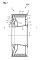
- Fig. 7 shows a longitudinally cut view of the generator 2 of fig. 6 .
- Fig. 8 shows the detail of fig. 7 in an enlarged view.
- two axially adjacently disposed rotor end plates 11a, 11b extend tilted relative to the centre axis A of the generator 2, whereby the rotor end plates 11a, 11b are tilted off the axial face side of the rotor 8 in an outward direction emanating from the centre axis A of the generator 2.
- the two rotor end plates 11a, 11b are disposed at the same axial face side of the rotor 9, i.e. the face side which is to be oriented towards the drive end 6 of a wind turbine 1.
- the radial inner ends of the respective rotor end plates 11a, 11b are disposed on the rotatable part of a bearing means 18, or a respective base ring 20 mounted to the bearing means 18 which bearing means 18 is axially connected to the stator shaft 12.
- the radially outer ends of the respective rotor end plates 11a, 11b converge in a common point at the face side of the rotor 8 facing the drive end 6 of a wind turbine 1.
- the rotor end plates 11a, 11b do not extend in parallel due to different tilting angles ⁇ 1 ⁇ 2 relative to the centre axis A of the generator 2 or a respective vertical axis, respectively.
- stator end plate 14a (front plate) oriented towards the drive-end 6 of a wind turbine 1 is partially tilted off the axial face side of the stator 9 in an outward direction emanating from the centre axis A of the generator 2.
- the stator end plate 14a comprises a first section perpendicularly extending relative to the centre axis A of the generator 2 and a second section extending tilted relative to the first section and to the centre axis A of the generator 2, respectively.
- the first section extends from the stator shaft 12, the second section essentially follows the first section in radial direction.
- the stator end plate 14b which is oriented towards the non-drive end 7 of a wind turbine 1 is not tilted, but extends perpendicularly relative to the centre axis A of the generator 2.
- the tilting angle ⁇ 3of the second section of the stator end plate 14a differs from the respective tilting angles ⁇ 1, ⁇ 2 of the rotor end plates 11a, 11b.
- the inventive principle i.e. the provision of respective rotor end plates 11, 11a, 11b and stator end plates 14a being at least partially tilted relative to the centre axis A of the generator 2 allows a generator design with a large depth while maintaining the stator shaft 12 comparatively short in axial direction.
- the inventive principle allows axially large generator dimensions in the region of the stator coils 17 and rotor permanent magnets 10 while keeping the weight of the generator 2 low.
- the provision of respective at least partially conically shaped, tiltedly extending rotor end plates 11, 11a, 11b and stator end plates 14a offers high stability against mechanical loads introduced in the direction of the centre axis A of the generator 2. Aside, the centre of mass may be located closer to the tower construction of a wind turbine 1.
Landscapes
- Engineering & Computer Science (AREA)
- Power Engineering (AREA)
- Life Sciences & Earth Sciences (AREA)
- Sustainable Energy (AREA)
- Sustainable Development (AREA)
- Chemical & Material Sciences (AREA)
- Combustion & Propulsion (AREA)
- Mechanical Engineering (AREA)
- General Engineering & Computer Science (AREA)
- Wind Motors (AREA)
- Connection Of Motors, Electrical Generators, Mechanical Devices, And The Like (AREA)
Abstract
Description
- The invention relates to a generator, particularly for a wind turbine, having a rotor and a stator, whereby the rotor comprises at least one disc-like shaped rotor end plate supporting the rotor and the stator comprises at least one disc-like shaped stator end plate supporting the stator.
- Generators such as used in wind turbines have to withstand high mechanical loads during operation. Particularly, large-scaled generators have to encounter huge axial and/or radial forces during operation, which forces are challenging for the generator support structure, i.e. respective support structures of the rotor and/or the stator in the shape of respective rotor end plates and/or stator end plates. Thereby, a concrete problem is the maintenance of a constant air-gap between the rotor and the stator.
- Hence, the support structure of the generator, i.e. particularly respective essentially radially extending rotor end plates and/or stator end plates, must be sufficiently stable so as to withstand structural loads or vibrations. Particularly, a collision of the rotor and the stator which would lead to considerable damage of the generator as a whole has to be avoided.
- The known approaches of support structures of modern, particularly large-scaled, generators are oftentimes not satisfying regarding their mechanical stability.
- It is the object of the present invention to provide a generator with improved mechanical stability.
- This is inventively achieved by a generator as initially described, wherein the at least one rotor end plate and/or the at least one stator end plate at least partially extends tilted relative to the centre axis of the generator.
- The inventive generator has an at least partially tilted, inclined, or conical rotor end plate and/or stator end plate leading to improved mechanical stability of the respective rotor and/or stator support structure. Particularly, the respective rotor and/or stator support structure is provided with additional mechanical stability against mechanical loads in the direction of the horizontally extending centre axis of the generator. As far as the inventive generator is part of a wind turbine, the centre of mass may be located closer to the tower construction of the wind turbine leading to improvements in the statics of the entire wind turbine construction. Further, the axial dimensions of a stator shaft supporting the stator may be reduced as well.
- The term "tilted" means that a respective rotor end plate and/or stator end plate or a respective section of a rotor end plate and/or stator end plate extends with a certain angle relative to the centre axis of the generator. Preferably, the respective rotor end plates and/or stator end plates are tilted off the axial face side of the rotor and/or stator in an outward direction emanating from the centre axis of the generator.
- Exemplary tilting angles of respective rotor end plates and/or stator end plates or respective sections of rotor end plates and/or stator end plates lie in the range of 1 - 70°, particularly 15 - 65°, in anti-clockwise or clockwise direction emanating from a vertical axis perpendicularly extending relative to the centre axis of the generator. Of course, exceptions or deviations from the named tilting angles are possible.
- As far as the inventive generator comprises more than one rotor end plate and/or stator end plate, the respective tilting angles may be equal or different. The same applies to the case, in which the inventive generator comprises at least one at least partially tilted rotor end plate and at least one at least partially tilted stator end plate.
- If the rotor end plate and/or the stator end plate only partially extends tilted relative to the centre axis of the generator, the respective rotor end plate and/or stator end plate comprises at least one first section perpendicularly extending relative to the centre axis of the generator and at least one second section extending tilted relative to the centre axis of the generator. It is possible that a respective rotor end plate and/or stator end plate comprises more than one respective first section and/or more than one respective second section. Usually, first sections are followed by second sections, and vice versa.
- Generally, the inventive design of respective rotor end plates and/or stator end plates allows constructing generators with a large depth while maintaining the stator shaft supporting the stator, i.e. the respective stator end plates, comparatively short in axial direction. In such a manner, comparatively low-weight generator constructions with large axial dimensions in the region of the stator coils (stator windings) and rotor permanent magnets are feasible.
- According to an exemplary embodiment of the invention, the stator comprises at least one stator end plate disposed at each axial face side of the stator, whereby respective stator end plates at least partially extend tilted relative to the centre axis of the generator only at one axial face side of the stator, or respective stator end plates at least partially extend tilted relative to the centre axis of the generator at both axial face sides of the stator. Thus, the stator may be supported by at least two respective stator end plates, i.e. at least one respective stator end plate is disposed at each face side of the stator. Thereby, respective stator end plates at least partially extend tilted relative to the centre axis of the generator at only one or both axial face sides of the stator. In the latter case, it is possible to further reduce the axial dimensions of the stator shaft.
- Likewise, it is possible that the rotor comprises at least one rotor end plate disposed at each axial face side of the rotor, whereby respective rotor end plates at least partially extend tilted relative to the centre axis of the generator only at one axial face side of the rotor, or respective rotor end plates at least partially extend tilted relative to the centre axis of the generator at both axial face sides of the rotor. Thus, the rotor may be supported by at least two respective rotor end plates, i.e. at least one respective rotor end plate is disposed at each face side of the rotor. Thereby, respective rotor end plates at least partially extend tilted relative to the centre axis of the generator at only one or both axial face sides of the rotor.
- As far as the generator is part of a wind turbine, the axial positions of respective bearing means supporting respective rotor end plates may be axially moved towards the tower construction of the wind turbine leading to the mentioned possibility of reducing the axial dimensions of the stator shaft usually supporting the stationary part of respective bearing means.
- It is thinkable that the rotor comprises two axially adjacently disposed rotor end plates at least partially extending tilted relative to the centre axis of the generator, whereby the rotor end plates are disposed at one axial face side of the rotor. In such a manner, the rotor is supported by two respective rotor end plates at one common face side of the rotor. Thereby, the rotor support structure may be further provided with improved mechanical stability. Of course, it is also possible that the rotor is provided with at least two respective rotor end plates at both face sides of the rotor.
- Likewise, it is possible that the stator comprises two axially adjacently disposed stator end plates at least partially extending tilted relative to the centre axis of the generator, whereby the stator end plates are disposed at one axial face side of the stator. In such a manner, the stator is supported by two respective stator end plates at one common face side of the stator. Thereby, the stator support structure is further provided with improved mechanical stability. Of course, it is also possible that the stator is provided with at least two respective stator end plates at both face sides of the stator.
- Thereby, the radially outer ends of the respective rotor end plates may converge in a common point at the axial face side of the rotor. Additionally or alternatively, the radially outer ends of the respective stator end plates may converge in a common point at the axial face side of the stator. Thus, the two respective rotor end plates and/or stator end plates being disposed at a common face side of the rotor or stator respectively do not extend in parallel, but converge in radial outward direction. That is, the respective rotor end plates and/or stator end plates comprise different tilting angles with respect to a vertical axis or the centre axis of the generator, respectively.
- As far as the respective rotor end plates and/or stator end plates disposed at a common face side of the rotor and/or stator extend in parallel or extend essentially parallel, i.e. do not converge in a common point at the face side of the rotor and/or stator, the tilting angles of respective rotor end plates and/or stator end plates are preferably equal with respect to a vertical axis or the centre axis of the generator, respectively.
- It is further possible that, if both at least one rotor end plate and at least one stator end plate at least partially extend tilted relative to the centre axis of the generator, the respective rotor and stator end plates are disposed at the same or opposite axial face sides of the generator. Thereby, it is preferred that respective rotor end plates and stator end plates are disposed at the same axial face side of the generator, i.e. the rotor and the stator, respectively. The tilting angles of the respective rotor end plate(s) and stator end plate(s) may be equal or different.
- According to a further embodiment of the inventive generator, at least one stator end plate comprises at least one aperture. As a rule, the term "aperture" refers to openings, through holes or the like. In such a manner, accessibility to the inside of the generator, particularly into the axial ring-space between the rotor and the stator is possible which may be necessary for maintenance and/or service works of respective components of the generator such as bearing means or the like. Additionally, respective apertures may serve as venting holes, i.e. allow the circulation of a gaseous cooling medium within the generator.
- Aside, the invention relates to a wind turbine, particularly a direct drive wind turbine, comprising at least one generator as described before. The generator is arranged within the wind turbine, i.e. a respective nacelle of the wind turbine for instance, in such a manner that one face side of the generator is oriented to the drive-end of the wind turbine corresponding to the side of the rotor hub and one face side of the generator is oriented to the non-drive end of the wind turbine corresponding to the side of the tower construction of the wind turbine.
- In the following, the invention is described in detail as reference is made to the figures, whereby:
- fig. 1
- shows a principle partial view of a wind turbine;
- fig. 2
- shows an axial view at the front side of a genera tor according to an exemplary embodiment;
- fig. 3
- shows a perspective view of the generator of
fig. 2 ; - fig. 4
- shows an axial view at the back side of a generator according to an exemplary embodiment;
- fig. 5
- shows a perspective view of the generator of
fig. 4 ; - fig. 6
- shows a perspective, partially cut view through a generator according to an exemplary embodiment;
- fig. 7
- shows a longitudinally cut view of the generator of
fig. 6 ; and - fig. 8
- shows the detail of
fig. 7 in an enlarged view. -
Fig. 1 shows a principle partial view of a wind turbine 1. The wind turbine 1 may be applicable for offshore applications. The wind turbine 1 is a direct drive wind turbine 1, i.e. thegenerator 2 of the wind turbine 1 is directly connected to the rotor hub 3 having respective rotor blades 4 attached thereto. Thus, thegenerator 2 is disposed between astructural component 5 of the wind turbine construction and the rotor hub 3. Thestructural component 5 may be a so called bedframe or the like. Hence, thegenerator 2 has one face side oriented towards thedrive end 6, i.e. the side of the rotor hub 3 of the wind turbine 1, and one face side oriented towards thenon-drive end 7 of the wind turbine construction, i.e. the side of thestructural component 5 of the wind turbine construction. -
Fig. 2 shows an axial view at the front side of agenerator 2 according to an exemplary embodiment. The front side of thegenerator 2 refers to the face side of thegenerator 2 which is oriented towards thedrive end 6 of the wind turbine 1 (cf.fig. 1 ).Fig. 3 shows a perspective view of thegenerator 2 offig. 2 . - The
generator 2 comprises a ring-like shapedrotor 8 and a ring-like shapedstator 9. Therotor 8 comprises respective rotor permanent magnets 10 (cf.fig. 7 ,8 for instance), thestator 9 comprises respective stator coils 17 (cf.fig. 7 ,8 for instance). An air-gap 19 extends between therotor 8 and the stator 9 (cf.fig. 7 ,8 for instance). - The
rotor 8 comprises disc-like shapedrotor end plates 11 supporting therotor 8 on and relative to an axially extendingstator shaft 12. As is particularly discernible fromfig. 3 in association withfig. 6 , the frontrotor end plate 11a particularly extends tilted relative to the centre axis A (rotational axis) of thegenerator 2. Further, ahub interface 13 is provided whichhub interface 13 serves to build a direct mechanical connection of therotor 8 and a rotor hub 3 of a wind turbine 1. -
Fig. 4 shows an axial view at the back side of agenerator 2 according to an exemplary embodiment. The back side of thegenerator 2 refers to the face side of thegenerator 2 which is oriented towards thenon-drive end 7 of a wind turbine 1 (cf.fig. 1 ).Fig. 5 shows a perspective view of thegenerator 2 offig. 4 . - The
stator 9 comprises respective disc-like shapedstator end plates 14 supporting thestator 9 on thestator shaft 12. Thestator 9 further comprises a windturbine construction interface 15 serving to provide a mechanical connection of thestator 9 with the construction of the wind turbine 1. - The
stator end plate 14 is provided withdiverse apertures 16 allowing maintenance and/or service personal to enter into the inside of thegenerator 2. Further,respective apertures 16 serve in terms of venting holes, i.e. allow the circulation of a gaseous cooling medium within thegenerator 2. Therefore, respective fans mounted between the stator coils 17,stator end plates 14 andstator shaft 12 are provided (not explicitly depicted). -
Fig. 4, 5 further depict respective rotorpermanent magnets 10 and stator coils 17 (stator windings). Thestator 9 may be segmented in circumferentially extending ring-segment-like shaped stator segments (not explicitly shown) adapted to build thestator 9 when assembled. Since therotor 8 surrounds thestator 9, thegenerator 2 has an outer rotor 8 -inner stator 9 configuration. -
Fig. 6 shows a perspective partially cut view through agenerator 2 according to an exemplary embodiment.Fig. 7 shows a longitudinally cut view of thegenerator 2 offig. 6 .Fig. 8 shows the detail offig. 7 in an enlarged view. - Regarding the
rotor 8, two axially adjacently disposedrotor end plates generator 2, whereby therotor end plates rotor 8 in an outward direction emanating from the centre axis A of thegenerator 2. The tworotor end plates rotor 9, i.e. the face side which is to be oriented towards thedrive end 6 of a wind turbine 1. The radial inner ends of the respectiverotor end plates respective base ring 20 mounted to the bearing means 18 which bearing means 18 is axially connected to thestator shaft 12. - The radially outer ends of the respective
rotor end plates rotor 8 facing thedrive end 6 of a wind turbine 1. Thus, therotor end plates generator 2 or a respective vertical axis, respectively. - Regarding the
stator 9, thestator end plate 14a (front plate) oriented towards the drive-end 6 of a wind turbine 1 is partially tilted off the axial face side of thestator 9 in an outward direction emanating from the centre axis A of thegenerator 2. Thestator end plate 14a comprises a first section perpendicularly extending relative to the centre axis A of thegenerator 2 and a second section extending tilted relative to the first section and to the centre axis A of thegenerator 2, respectively. As is discernible fromfig. 6 ,7 ,8 , the first section extends from thestator shaft 12, the second section essentially follows the first section in radial direction. - The
stator end plate 14b which is oriented towards thenon-drive end 7 of a wind turbine 1 is not tilted, but extends perpendicularly relative to the centre axis A of thegenerator 2. The tilting angle α3of the second section of thestator end plate 14a differs from the respective tilting angles α1, α2 of therotor end plates - The inventive principle, i.e. the provision of respective
rotor end plates stator end plates 14a being at least partially tilted relative to the centre axis A of thegenerator 2 allows a generator design with a large depth while maintaining thestator shaft 12 comparatively short in axial direction. The inventive principle allows axially large generator dimensions in the region of the stator coils 17 and rotorpermanent magnets 10 while keeping the weight of thegenerator 2 low. The provision of respective at least partially conically shaped, tiltedly extendingrotor end plates stator end plates 14a offers high stability against mechanical loads introduced in the direction of the centre axis A of thegenerator 2. Aside, the centre of mass may be located closer to the tower construction of a wind turbine 1. - Although the present invention has been described in detail with reference to the preferred embodiment, the present invention is not limited by the disclosed examples from which the skilled person is able to derive other variations without departing from the scope of the invention.
Claims (14)
- Generator (2), particularly for a wind turbine (1), having a rotor (8) and a stator (9), whereby the rotor (8) comprises at least one disc-like shaped rotor end plate (11, 11a, 11b) supporting the rotor (8) and the stator (9) comprises at least one disc-like shaped stator end plate (14, 14a, 14b) supporting the stator (9), wherein the at least one rotor end plate (11, 11a, 11b) and/or the at least one stator end plate (14, 14a, 14b) at least partially extends tilted relative to the centre axis (A) of the generator (2).
- Generator according to claim 1, wherein the stator (9) comprises at least one stator end plate (14, 14a, 14b) disposed at each axial face side of the stator, whereby respective stator end plates (14, 14a, 14b) at least partially extend tilted relative to the centre axis (A) of the generator (2) only at one axial face side of the stator (9), or respective stator end plates (14, 14a, 14b) at least partially extend tilted relative to the centre axis (A) of the generator (2) at both axial face sides of the stator (9).
- Generator according to claim 1 or 2, wherein the rotor (8) comprises at least one rotor end plate (11, 11a, 11b) disposed at each axial face side of the rotor (8), whereby respective rotor end plates (11, 11a, 11b) at least partially extend tilted relative to the centre axis (A) of the generator (2) only at one axial face side of the rotor (8), or respective rotor end plates (11, 11a, 11b) at least partially extend tilted relative to the centre axis (A) of the generator (2) at both axial face sides of the rotor (8).
- Generator according to one of the preceding claims, wherein the rotor (8) comprises two axially adjacently disposed rotor end plates (11a, 11b) at least partially extending tilted relative to the centre axis (A) of the generator (2), whereby the rotor end plates (11a, 11b) are disposed at one axial face side of the rotor (8).
- Generator according to one of the preceding claims, wherein the stator (9) comprises two axially adjacently disposed stator end plates at least partially extending tilted relative to the centre axis (A) of the generator (2), whereby the stator end plates are disposed at one axial face side of the stator (9) .
- Generator according to claim 4 or 5, wherein the radially outer ends of the respective rotor end plates (11a, 11b) converge in a common point at the axial face side of the rotor (9) and/or the radially outer ends of the respective stator end plates converge in a common point at the axial face side of the stator (8).
- Generator according to one of the claims 4 to 6, wherein the tilting angles (α1, α2) of the respective rotor end plates (11a, 11b) and/or stator end plates are equal or different.
- Generator according to one of the preceding claims, wherein, if both at least one rotor end plate (11, 11a, 11b) and at least one stator end plate (14, 14a, 14b) at least partially extend tilted relative to the centre axis (A) of the generator (2), the respective rotor end plates (11, 11a, 11b) and stator end plates (14, 14a, 14b) are disposed at the same or opposite axial face sides of the generator (2).
- Generator according to claim 8, wherein the tilting angles (α1, α2, α3) of the respective rotor end plate (11, 11a, 11b) and the respective stator end plate (14, 14a) are equal or different.
- Generator according to one of the preceding claims, wherein, if the rotor end plate and/or the stator end plate (14a) partially extends tilted relative to the centre axis (A) of the generator (2), the respective rotor end plate and/or stator end plate (14, 14a) comprises at least one first section perpendicularly extending relative to the centre axis (A) of the generator (2) and at least one second section extending tilted relative to the centre axis (A) of the generator (2).
- Generator according to one of the preceding claims, wherein the respective rotor end plates (11, 11a, 11b) and/or stator end plates (14, 14a, 14b) are tilted off the axial face side of the rotor (8) and/or stator (9) in an outward direction emanating from the centre axis (A) of the generator (2).
- Generator according to one of the preceding claims, wherein the tilting angle (α1, α2, α3) of respective tilted sections of rotor end plates (11, 11a, 11b) and/or stator end plates (14a) lies in the range of 1 - 70°, particularly 15 - 65°, in anti-clockwise or clockwise direction emanating from a vertical axis.
- Generator according to one of the preceding claims, wherein at least one stator end plate (14, 14a, 14b) comprises at least one aperture (16).
- Wind turbine (1), particularly direct drive wind turbine, comprising at least one generator (2) according to one of the preceding claims, whereby one face side of the generator (2) is oriented towards the drive-end (6) of the wind turbine (1) and one face side of the generator 82) is oriented towards the non-drive end (7) of the wind turbine (1).
Priority Applications (3)
| Application Number | Priority Date | Filing Date | Title |
|---|---|---|---|
| EP11183806.6A EP2578872B1 (en) | 2011-10-04 | 2011-10-04 | Generator |
| US13/615,716 US9407123B2 (en) | 2011-10-04 | 2012-09-14 | Generator with support structure |
| CN201210370954.2A CN103036337B (en) | 2011-10-04 | 2012-09-29 | Generator |
Applications Claiming Priority (1)
| Application Number | Priority Date | Filing Date | Title |
|---|---|---|---|
| EP11183806.6A EP2578872B1 (en) | 2011-10-04 | 2011-10-04 | Generator |
Publications (2)
| Publication Number | Publication Date |
|---|---|
| EP2578872A1 true EP2578872A1 (en) | 2013-04-10 |
| EP2578872B1 EP2578872B1 (en) | 2018-01-03 |
Family
ID=44903082
Family Applications (1)
| Application Number | Title | Priority Date | Filing Date |
|---|---|---|---|
| EP11183806.6A Active EP2578872B1 (en) | 2011-10-04 | 2011-10-04 | Generator |
Country Status (3)
| Country | Link |
|---|---|
| US (1) | US9407123B2 (en) |
| EP (1) | EP2578872B1 (en) |
| CN (1) | CN103036337B (en) |
Cited By (2)
| Publication number | Priority date | Publication date | Assignee | Title |
|---|---|---|---|---|
| EP2843810A1 (en) | 2013-09-03 | 2015-03-04 | Siemens Aktiengesellschaft | Generator for a wind turbine |
| EP3849064A1 (en) * | 2020-01-10 | 2021-07-14 | Siemens Gamesa Renewable Energy A/S | Segment for a generator of a wind turbine |
Families Citing this family (5)
| Publication number | Priority date | Publication date | Assignee | Title |
|---|---|---|---|---|
| EP3024126A1 (en) * | 2014-11-20 | 2016-05-25 | Siemens Aktiengesellschaft | Cooling arrangement |
| EP3226383A1 (en) * | 2016-03-30 | 2017-10-04 | Siemens Aktiengesellschaft | Stator assembly for an electric generator with accommodation space |
| US12051949B2 (en) | 2021-01-19 | 2024-07-30 | Mahle International Gmbh | Asymmetrical skewed rotor |
| EP4135159A1 (en) * | 2021-08-13 | 2023-02-15 | Siemens Gamesa Renewable Energy A/S | Stator of an electric generator having a reinforcement structure |
| CN113765326A (en) * | 2021-10-11 | 2021-12-07 | 维沃移动通信有限公司 | Linear motor and vibration direction detection method, device and electronic equipment thereof |
Citations (4)
| Publication number | Priority date | Publication date | Assignee | Title |
|---|---|---|---|---|
| DE4402184A1 (en) * | 1994-01-26 | 1995-08-03 | Friedrich Prof Dr Ing Klinger | Multi-pole synchronous generator for gearless horizontal-axis wind turbines with nominal powers of up to several megawatts |
| EP1612415A2 (en) * | 2004-06-30 | 2006-01-04 | General Electric Company | Electrical machine with double-sided rotor |
| US20070103027A1 (en) * | 2004-09-27 | 2007-05-10 | Jansen Patrick L | Electrical machine with double-sided lamination stack |
| EP2014917A1 (en) * | 2007-07-10 | 2009-01-14 | Siemens Aktiengesellschaft | Minimising wind turbine generator air gap with a specific shaft bearing arrangement |
Family Cites Families (7)
| Publication number | Priority date | Publication date | Assignee | Title |
|---|---|---|---|---|
| KR100695012B1 (en) * | 2006-03-24 | 2007-03-14 | 유니슨 주식회사 | Wind generator |
| US7538446B2 (en) * | 2007-06-21 | 2009-05-26 | General Electric Company | Gear integrated generator for wind turbine |
| EP2063114A1 (en) * | 2007-11-26 | 2009-05-27 | Siemens Aktiengesellschaft | Wind turbine |
| NL2001190C1 (en) * | 2008-01-16 | 2009-07-20 | Lagerwey Wind B V | Generator for a direct-driven wind turbine. |
| EE200800049A (en) * | 2008-07-24 | 2010-04-15 | S?najalg Andres | Wind generator |
| DE102009017865A1 (en) * | 2009-04-17 | 2010-10-28 | Schuler Pressen Gmbh & Co. Kg | Generator arrangement for wind energy plant |
| EP2437380A1 (en) * | 2010-09-30 | 2012-04-04 | Siemens Aktiengesellschaft | Rotor, generator and wind turbine |
-
2011
- 2011-10-04 EP EP11183806.6A patent/EP2578872B1/en active Active
-
2012
- 2012-09-14 US US13/615,716 patent/US9407123B2/en active Active
- 2012-09-29 CN CN201210370954.2A patent/CN103036337B/en active Active
Patent Citations (4)
| Publication number | Priority date | Publication date | Assignee | Title |
|---|---|---|---|---|
| DE4402184A1 (en) * | 1994-01-26 | 1995-08-03 | Friedrich Prof Dr Ing Klinger | Multi-pole synchronous generator for gearless horizontal-axis wind turbines with nominal powers of up to several megawatts |
| EP1612415A2 (en) * | 2004-06-30 | 2006-01-04 | General Electric Company | Electrical machine with double-sided rotor |
| US20070103027A1 (en) * | 2004-09-27 | 2007-05-10 | Jansen Patrick L | Electrical machine with double-sided lamination stack |
| EP2014917A1 (en) * | 2007-07-10 | 2009-01-14 | Siemens Aktiengesellschaft | Minimising wind turbine generator air gap with a specific shaft bearing arrangement |
Cited By (5)
| Publication number | Priority date | Publication date | Assignee | Title |
|---|---|---|---|---|
| EP2843810A1 (en) | 2013-09-03 | 2015-03-04 | Siemens Aktiengesellschaft | Generator for a wind turbine |
| EP3849064A1 (en) * | 2020-01-10 | 2021-07-14 | Siemens Gamesa Renewable Energy A/S | Segment for a generator of a wind turbine |
| WO2021139926A1 (en) * | 2020-01-10 | 2021-07-15 | Siemens Gamesa Renewable Energy A/S | Segment for a generator of a wind turbine |
| CN114902538A (en) * | 2020-01-10 | 2022-08-12 | 西门子歌美飒可再生能源公司 | Section of a generator for a wind turbine |
| US12176758B2 (en) | 2020-01-10 | 2024-12-24 | Siemens Gamesa Renewable Energy A/S | Segment for a generator of a wind turbine |
Also Published As
| Publication number | Publication date |
|---|---|
| US9407123B2 (en) | 2016-08-02 |
| US20130241365A1 (en) | 2013-09-19 |
| CN103036337A (en) | 2013-04-10 |
| EP2578872B1 (en) | 2018-01-03 |
| CN103036337B (en) | 2017-09-15 |
Similar Documents
| Publication | Publication Date | Title |
|---|---|---|
| EP2578872B1 (en) | Generator | |
| CN101459354B (en) | Direct drive generator and wind turbine | |
| JP5751747B2 (en) | Stator arrangement, generator and wind turbine | |
| US8710720B2 (en) | Generator with a segmented stator | |
| EP2143944B1 (en) | Wind turbine | |
| DK2657519T3 (en) | Windmill | |
| EP2063114A1 (en) | Wind turbine | |
| US8536753B2 (en) | Arrangement to ensure an air gap in an electric machine | |
| CN101447703A (en) | Direct drive generator and wind turbine | |
| EP2143941A1 (en) | Direct drive generator and wind turbine | |
| CN101521414A (en) | Arrangement for a direct drive generator, direct drive generator, wind turbine and method for the assembly of a generator | |
| CN1554144A (en) | Wind power generator | |
| CN102695875A (en) | Wind turbine | |
| EP2143942A1 (en) | Wine turbine | |
| JP2011526985A (en) | Wind turbine with main bearing and replacement method of main bearing | |
| JP2015519033A (en) | Synchronous generator for gearless wind turbine generator | |
| EP2492503B1 (en) | A wind turbine with a generator | |
| CN114514671B (en) | Support structure for a generator of a wind turbine | |
| US10472792B2 (en) | Tower flange for a wind turbine | |
| EP4140018A1 (en) | Segment support structure for a generator of a wind turbine | |
| US12381461B2 (en) | Airgap control in an electric generator for a wind turbine | |
| KR102866685B1 (en) | Support structure segments for the stator of the generator of a wind turbine and the wind turbine | |
| JP2017180232A (en) | Air turbine device |
Legal Events
| Date | Code | Title | Description |
|---|---|---|---|
| PUAI | Public reference made under article 153(3) epc to a published international application that has entered the european phase |
Free format text: ORIGINAL CODE: 0009012 |
|
| AK | Designated contracting states |
Kind code of ref document: A1 Designated state(s): AL AT BE BG CH CY CZ DE DK EE ES FI FR GB GR HR HU IE IS IT LI LT LU LV MC MK MT NL NO PL PT RO RS SE SI SK SM TR |
|
| AX | Request for extension of the european patent |
Extension state: BA ME |
|
| 17P | Request for examination filed |
Effective date: 20130605 |
|
| RBV | Designated contracting states (corrected) |
Designated state(s): AL AT BE BG CH CY CZ DE DK EE ES FI FR GB GR HR HU IE IS IT LI LT LU LV MC MK MT NL NO PL PT RO RS SE SI SK SM TR |
|
| 17Q | First examination report despatched |
Effective date: 20160930 |
|
| REG | Reference to a national code |
Ref country code: DE Ref legal event code: R079 Ref document number: 602011044681 Country of ref document: DE Free format text: PREVIOUS MAIN CLASS: F03D0001000000 Ipc: H02K0001180000 |
|
| GRAP | Despatch of communication of intention to grant a patent |
Free format text: ORIGINAL CODE: EPIDOSNIGR1 |
|
| RIC1 | Information provided on ipc code assigned before grant |
Ipc: F03D 80/50 20160101ALI20170623BHEP Ipc: H02K 7/18 20060101ALI20170623BHEP Ipc: H02K 5/15 20060101ALI20170623BHEP Ipc: H02K 1/18 20060101AFI20170623BHEP Ipc: H02K 7/08 20060101ALI20170623BHEP Ipc: H02K 1/28 20060101ALI20170623BHEP Ipc: H02K 5/22 20060101ALI20170623BHEP Ipc: H02K 1/27 20060101ALI20170623BHEP |
|
| INTG | Intention to grant announced |
Effective date: 20170726 |
|
| RAP1 | Party data changed (applicant data changed or rights of an application transferred) |
Owner name: SIEMENS AKTIENGESELLSCHAFT |
|
| GRAS | Grant fee paid |
Free format text: ORIGINAL CODE: EPIDOSNIGR3 |
|
| GRAA | (expected) grant |
Free format text: ORIGINAL CODE: 0009210 |
|
| AK | Designated contracting states |
Kind code of ref document: B1 Designated state(s): AL AT BE BG CH CY CZ DE DK EE ES FI FR GB GR HR HU IE IS IT LI LT LU LV MC MK MT NL NO PL PT RO RS SE SI SK SM TR |
|
| REG | Reference to a national code |
Ref country code: GB Ref legal event code: FG4D |
|
| REG | Reference to a national code |
Ref country code: CH Ref legal event code: EP Ref country code: AT Ref legal event code: REF Ref document number: 961118 Country of ref document: AT Kind code of ref document: T Effective date: 20180115 |
|
| REG | Reference to a national code |
Ref country code: IE Ref legal event code: FG4D |
|
| REG | Reference to a national code |
Ref country code: DE Ref legal event code: R096 Ref document number: 602011044681 Country of ref document: DE |
|
| REG | Reference to a national code |
Ref country code: NL Ref legal event code: FP |
|
| REG | Reference to a national code |
Ref country code: LT Ref legal event code: MG4D |
|
| REG | Reference to a national code |
Ref country code: AT Ref legal event code: MK05 Ref document number: 961118 Country of ref document: AT Kind code of ref document: T Effective date: 20180103 |
|
| PG25 | Lapsed in a contracting state [announced via postgrant information from national office to epo] |
Ref country code: FI Free format text: LAPSE BECAUSE OF FAILURE TO SUBMIT A TRANSLATION OF THE DESCRIPTION OR TO PAY THE FEE WITHIN THE PRESCRIBED TIME-LIMIT Effective date: 20180103 Ref country code: LT Free format text: LAPSE BECAUSE OF FAILURE TO SUBMIT A TRANSLATION OF THE DESCRIPTION OR TO PAY THE FEE WITHIN THE PRESCRIBED TIME-LIMIT Effective date: 20180103 Ref country code: CY Free format text: LAPSE BECAUSE OF FAILURE TO SUBMIT A TRANSLATION OF THE DESCRIPTION OR TO PAY THE FEE WITHIN THE PRESCRIBED TIME-LIMIT Effective date: 20180103 Ref country code: ES Free format text: LAPSE BECAUSE OF FAILURE TO SUBMIT A TRANSLATION OF THE DESCRIPTION OR TO PAY THE FEE WITHIN THE PRESCRIBED TIME-LIMIT Effective date: 20180103 Ref country code: NO Free format text: LAPSE BECAUSE OF FAILURE TO SUBMIT A TRANSLATION OF THE DESCRIPTION OR TO PAY THE FEE WITHIN THE PRESCRIBED TIME-LIMIT Effective date: 20180403 Ref country code: HR Free format text: LAPSE BECAUSE OF FAILURE TO SUBMIT A TRANSLATION OF THE DESCRIPTION OR TO PAY THE FEE WITHIN THE PRESCRIBED TIME-LIMIT Effective date: 20180103 |
|
| PG25 | Lapsed in a contracting state [announced via postgrant information from national office to epo] |
Ref country code: RS Free format text: LAPSE BECAUSE OF FAILURE TO SUBMIT A TRANSLATION OF THE DESCRIPTION OR TO PAY THE FEE WITHIN THE PRESCRIBED TIME-LIMIT Effective date: 20180103 Ref country code: AT Free format text: LAPSE BECAUSE OF FAILURE TO SUBMIT A TRANSLATION OF THE DESCRIPTION OR TO PAY THE FEE WITHIN THE PRESCRIBED TIME-LIMIT Effective date: 20180103 Ref country code: PL Free format text: LAPSE BECAUSE OF FAILURE TO SUBMIT A TRANSLATION OF THE DESCRIPTION OR TO PAY THE FEE WITHIN THE PRESCRIBED TIME-LIMIT Effective date: 20180103 Ref country code: BG Free format text: LAPSE BECAUSE OF FAILURE TO SUBMIT A TRANSLATION OF THE DESCRIPTION OR TO PAY THE FEE WITHIN THE PRESCRIBED TIME-LIMIT Effective date: 20180403 Ref country code: GR Free format text: LAPSE BECAUSE OF FAILURE TO SUBMIT A TRANSLATION OF THE DESCRIPTION OR TO PAY THE FEE WITHIN THE PRESCRIBED TIME-LIMIT Effective date: 20180404 Ref country code: LV Free format text: LAPSE BECAUSE OF FAILURE TO SUBMIT A TRANSLATION OF THE DESCRIPTION OR TO PAY THE FEE WITHIN THE PRESCRIBED TIME-LIMIT Effective date: 20180103 Ref country code: IS Free format text: LAPSE BECAUSE OF FAILURE TO SUBMIT A TRANSLATION OF THE DESCRIPTION OR TO PAY THE FEE WITHIN THE PRESCRIBED TIME-LIMIT Effective date: 20180503 Ref country code: SE Free format text: LAPSE BECAUSE OF FAILURE TO SUBMIT A TRANSLATION OF THE DESCRIPTION OR TO PAY THE FEE WITHIN THE PRESCRIBED TIME-LIMIT Effective date: 20180103 |
|
| REG | Reference to a national code |
Ref country code: DE Ref legal event code: R097 Ref document number: 602011044681 Country of ref document: DE |
|
| REG | Reference to a national code |
Ref country code: FR Ref legal event code: PLFP Year of fee payment: 8 |
|
| PG25 | Lapsed in a contracting state [announced via postgrant information from national office to epo] |
Ref country code: AL Free format text: LAPSE BECAUSE OF FAILURE TO SUBMIT A TRANSLATION OF THE DESCRIPTION OR TO PAY THE FEE WITHIN THE PRESCRIBED TIME-LIMIT Effective date: 20180103 Ref country code: RO Free format text: LAPSE BECAUSE OF FAILURE TO SUBMIT A TRANSLATION OF THE DESCRIPTION OR TO PAY THE FEE WITHIN THE PRESCRIBED TIME-LIMIT Effective date: 20180103 Ref country code: EE Free format text: LAPSE BECAUSE OF FAILURE TO SUBMIT A TRANSLATION OF THE DESCRIPTION OR TO PAY THE FEE WITHIN THE PRESCRIBED TIME-LIMIT Effective date: 20180103 Ref country code: IT Free format text: LAPSE BECAUSE OF FAILURE TO SUBMIT A TRANSLATION OF THE DESCRIPTION OR TO PAY THE FEE WITHIN THE PRESCRIBED TIME-LIMIT Effective date: 20180103 |
|
| PLBE | No opposition filed within time limit |
Free format text: ORIGINAL CODE: 0009261 |
|
| STAA | Information on the status of an ep patent application or granted ep patent |
Free format text: STATUS: NO OPPOSITION FILED WITHIN TIME LIMIT |
|
| PG25 | Lapsed in a contracting state [announced via postgrant information from national office to epo] |
Ref country code: CZ Free format text: LAPSE BECAUSE OF FAILURE TO SUBMIT A TRANSLATION OF THE DESCRIPTION OR TO PAY THE FEE WITHIN THE PRESCRIBED TIME-LIMIT Effective date: 20180103 Ref country code: SK Free format text: LAPSE BECAUSE OF FAILURE TO SUBMIT A TRANSLATION OF THE DESCRIPTION OR TO PAY THE FEE WITHIN THE PRESCRIBED TIME-LIMIT Effective date: 20180103 Ref country code: SM Free format text: LAPSE BECAUSE OF FAILURE TO SUBMIT A TRANSLATION OF THE DESCRIPTION OR TO PAY THE FEE WITHIN THE PRESCRIBED TIME-LIMIT Effective date: 20180103 Ref country code: DK Free format text: LAPSE BECAUSE OF FAILURE TO SUBMIT A TRANSLATION OF THE DESCRIPTION OR TO PAY THE FEE WITHIN THE PRESCRIBED TIME-LIMIT Effective date: 20180103 |
|
| 26N | No opposition filed |
Effective date: 20181005 |
|
| PG25 | Lapsed in a contracting state [announced via postgrant information from national office to epo] |
Ref country code: SI Free format text: LAPSE BECAUSE OF FAILURE TO SUBMIT A TRANSLATION OF THE DESCRIPTION OR TO PAY THE FEE WITHIN THE PRESCRIBED TIME-LIMIT Effective date: 20180103 |
|
| REG | Reference to a national code |
Ref country code: CH Ref legal event code: PL |
|
| REG | Reference to a national code |
Ref country code: BE Ref legal event code: MM Effective date: 20181031 |
|
| PG25 | Lapsed in a contracting state [announced via postgrant information from national office to epo] |
Ref country code: LU Free format text: LAPSE BECAUSE OF NON-PAYMENT OF DUE FEES Effective date: 20181004 Ref country code: MC Free format text: LAPSE BECAUSE OF FAILURE TO SUBMIT A TRANSLATION OF THE DESCRIPTION OR TO PAY THE FEE WITHIN THE PRESCRIBED TIME-LIMIT Effective date: 20180103 |
|
| REG | Reference to a national code |
Ref country code: IE Ref legal event code: MM4A |
|
| PG25 | Lapsed in a contracting state [announced via postgrant information from national office to epo] |
Ref country code: CH Free format text: LAPSE BECAUSE OF NON-PAYMENT OF DUE FEES Effective date: 20181031 Ref country code: BE Free format text: LAPSE BECAUSE OF NON-PAYMENT OF DUE FEES Effective date: 20181031 Ref country code: LI Free format text: LAPSE BECAUSE OF NON-PAYMENT OF DUE FEES Effective date: 20181031 |
|
| REG | Reference to a national code |
Ref country code: DE Ref legal event code: R081 Ref document number: 602011044681 Country of ref document: DE Owner name: SIEMENS GAMESA RENEWABLE ENERGY A/S, DK Free format text: FORMER OWNER: SIEMENS AKTIENGESELLSCHAFT, 80333 MUENCHEN, DE |
|
| PG25 | Lapsed in a contracting state [announced via postgrant information from national office to epo] |
Ref country code: IE Free format text: LAPSE BECAUSE OF NON-PAYMENT OF DUE FEES Effective date: 20181004 |
|
| REG | Reference to a national code |
Ref country code: GB Ref legal event code: 732E Free format text: REGISTERED BETWEEN 20191128 AND 20191204 |
|
| PG25 | Lapsed in a contracting state [announced via postgrant information from national office to epo] |
Ref country code: MT Free format text: LAPSE BECAUSE OF NON-PAYMENT OF DUE FEES Effective date: 20181004 |
|
| PG25 | Lapsed in a contracting state [announced via postgrant information from national office to epo] |
Ref country code: TR Free format text: LAPSE BECAUSE OF FAILURE TO SUBMIT A TRANSLATION OF THE DESCRIPTION OR TO PAY THE FEE WITHIN THE PRESCRIBED TIME-LIMIT Effective date: 20180103 |
|
| PG25 | Lapsed in a contracting state [announced via postgrant information from national office to epo] |
Ref country code: PT Free format text: LAPSE BECAUSE OF FAILURE TO SUBMIT A TRANSLATION OF THE DESCRIPTION OR TO PAY THE FEE WITHIN THE PRESCRIBED TIME-LIMIT Effective date: 20180103 |
|
| PG25 | Lapsed in a contracting state [announced via postgrant information from national office to epo] |
Ref country code: HU Free format text: LAPSE BECAUSE OF FAILURE TO SUBMIT A TRANSLATION OF THE DESCRIPTION OR TO PAY THE FEE WITHIN THE PRESCRIBED TIME-LIMIT; INVALID AB INITIO Effective date: 20111004 Ref country code: MK Free format text: LAPSE BECAUSE OF NON-PAYMENT OF DUE FEES Effective date: 20180103 |
|
| REG | Reference to a national code |
Ref country code: NL Ref legal event code: PD Owner name: SIEMENS GAMESA RENEWABLE ENERGY A/S; DK Free format text: DETAILS ASSIGNMENT: CHANGE OF OWNER(S), ASSIGNMENT; FORMER OWNER NAME: SIEMENS AKTIENGESELLSCHAFT Effective date: 20201126 |
|
| REG | Reference to a national code |
Ref country code: DE Ref legal event code: R082 Ref document number: 602011044681 Country of ref document: DE Representative=s name: SAUTHOFF, KARSTEN, DIPL.-ING. UNIV., DE |
|
| REG | Reference to a national code |
Ref country code: FR Ref legal event code: PLFP Year of fee payment: 12 |
|
| PGFP | Annual fee paid to national office [announced via postgrant information from national office to epo] |
Ref country code: NL Payment date: 20241023 Year of fee payment: 14 |
|
| PGFP | Annual fee paid to national office [announced via postgrant information from national office to epo] |
Ref country code: GB Payment date: 20250901 Year of fee payment: 15 |
|
| PGFP | Annual fee paid to national office [announced via postgrant information from national office to epo] |
Ref country code: DE Payment date: 20250731 Year of fee payment: 15 |
|
| PGFP | Annual fee paid to national office [announced via postgrant information from national office to epo] |
Ref country code: FR Payment date: 20251027 Year of fee payment: 15 |