EP2578871A1 - Method for controlling a motor-vehicle provided with an internal combustion engine having a system for variable actuation of the intake valves - Google Patents
Method for controlling a motor-vehicle provided with an internal combustion engine having a system for variable actuation of the intake valves Download PDFInfo
- Publication number
- EP2578871A1 EP2578871A1 EP11183663.1A EP11183663A EP2578871A1 EP 2578871 A1 EP2578871 A1 EP 2578871A1 EP 11183663 A EP11183663 A EP 11183663A EP 2578871 A1 EP2578871 A1 EP 2578871A1
- Authority
- EP
- European Patent Office
- Prior art keywords
- engine
- intake valves
- internal combustion
- combustion engine
- intake
- Prior art date
- Legal status (The legal status is an assumption and is not a legal conclusion. Google has not performed a legal analysis and makes no representation as to the accuracy of the status listed.)
- Granted
Links
Images


Classifications
-
- F—MECHANICAL ENGINEERING; LIGHTING; HEATING; WEAPONS; BLASTING
- F02—COMBUSTION ENGINES; HOT-GAS OR COMBUSTION-PRODUCT ENGINE PLANTS
- F02D—CONTROLLING COMBUSTION ENGINES
- F02D13/00—Controlling the engine output power by varying inlet or exhaust valve operating characteristics, e.g. timing
- F02D13/02—Controlling the engine output power by varying inlet or exhaust valve operating characteristics, e.g. timing during engine operation
- F02D13/0223—Variable control of the intake valves only
- F02D13/0234—Variable control of the intake valves only changing the valve timing only
- F02D13/0238—Variable control of the intake valves only changing the valve timing only by shifting the phase, i.e. the opening periods of the valves are constant
-
- F—MECHANICAL ENGINEERING; LIGHTING; HEATING; WEAPONS; BLASTING
- F01—MACHINES OR ENGINES IN GENERAL; ENGINE PLANTS IN GENERAL; STEAM ENGINES
- F01L—CYCLICALLY OPERATING VALVES FOR MACHINES OR ENGINES
- F01L1/00—Valve-gear or valve arrangements, e.g. lift-valve gear
- F01L1/02—Valve drive
- F01L1/04—Valve drive by means of cams, camshafts, cam discs, eccentrics or the like
- F01L1/08—Shape of cams
-
- F—MECHANICAL ENGINEERING; LIGHTING; HEATING; WEAPONS; BLASTING
- F01—MACHINES OR ENGINES IN GENERAL; ENGINE PLANTS IN GENERAL; STEAM ENGINES
- F01L—CYCLICALLY OPERATING VALVES FOR MACHINES OR ENGINES
- F01L13/00—Modifications of valve-gear to facilitate reversing, braking, starting, changing compression ratio, or other specific operations
- F01L13/0015—Modifications of valve-gear to facilitate reversing, braking, starting, changing compression ratio, or other specific operations for optimising engine performances by modifying valve lift according to various working parameters, e.g. rotational speed, load, torque
-
- F—MECHANICAL ENGINEERING; LIGHTING; HEATING; WEAPONS; BLASTING
- F01—MACHINES OR ENGINES IN GENERAL; ENGINE PLANTS IN GENERAL; STEAM ENGINES
- F01L—CYCLICALLY OPERATING VALVES FOR MACHINES OR ENGINES
- F01L13/00—Modifications of valve-gear to facilitate reversing, braking, starting, changing compression ratio, or other specific operations
- F01L13/0015—Modifications of valve-gear to facilitate reversing, braking, starting, changing compression ratio, or other specific operations for optimising engine performances by modifying valve lift according to various working parameters, e.g. rotational speed, load, torque
- F01L13/0021—Modifications of valve-gear to facilitate reversing, braking, starting, changing compression ratio, or other specific operations for optimising engine performances by modifying valve lift according to various working parameters, e.g. rotational speed, load, torque by modification of rocker arm ratio
- F01L13/0026—Modifications of valve-gear to facilitate reversing, braking, starting, changing compression ratio, or other specific operations for optimising engine performances by modifying valve lift according to various working parameters, e.g. rotational speed, load, torque by modification of rocker arm ratio by means of an eccentric
-
- F—MECHANICAL ENGINEERING; LIGHTING; HEATING; WEAPONS; BLASTING
- F01—MACHINES OR ENGINES IN GENERAL; ENGINE PLANTS IN GENERAL; STEAM ENGINES
- F01L—CYCLICALLY OPERATING VALVES FOR MACHINES OR ENGINES
- F01L9/00—Valve-gear or valve arrangements actuated non-mechanically
- F01L9/10—Valve-gear or valve arrangements actuated non-mechanically by fluid means, e.g. hydraulic
- F01L9/11—Valve-gear or valve arrangements actuated non-mechanically by fluid means, e.g. hydraulic in which the action of a cam is being transmitted to a valve by a liquid column
- F01L9/12—Valve-gear or valve arrangements actuated non-mechanically by fluid means, e.g. hydraulic in which the action of a cam is being transmitted to a valve by a liquid column with a liquid chamber between a piston actuated by a cam and a piston acting on a valve stem
- F01L9/14—Valve-gear or valve arrangements actuated non-mechanically by fluid means, e.g. hydraulic in which the action of a cam is being transmitted to a valve by a liquid column with a liquid chamber between a piston actuated by a cam and a piston acting on a valve stem the volume of the chamber being variable, e.g. for varying the lift or the timing of a valve
-
- F—MECHANICAL ENGINEERING; LIGHTING; HEATING; WEAPONS; BLASTING
- F02—COMBUSTION ENGINES; HOT-GAS OR COMBUSTION-PRODUCT ENGINE PLANTS
- F02D—CONTROLLING COMBUSTION ENGINES
- F02D13/00—Controlling the engine output power by varying inlet or exhaust valve operating characteristics, e.g. timing
- F02D13/02—Controlling the engine output power by varying inlet or exhaust valve operating characteristics, e.g. timing during engine operation
- F02D13/0203—Variable control of intake and exhaust valves
- F02D13/0207—Variable control of intake and exhaust valves changing valve lift or valve lift and timing
-
- F—MECHANICAL ENGINEERING; LIGHTING; HEATING; WEAPONS; BLASTING
- F02—COMBUSTION ENGINES; HOT-GAS OR COMBUSTION-PRODUCT ENGINE PLANTS
- F02D—CONTROLLING COMBUSTION ENGINES
- F02D13/00—Controlling the engine output power by varying inlet or exhaust valve operating characteristics, e.g. timing
- F02D13/02—Controlling the engine output power by varying inlet or exhaust valve operating characteristics, e.g. timing during engine operation
- F02D13/0203—Variable control of intake and exhaust valves
- F02D13/0215—Variable control of intake and exhaust valves changing the valve timing only
-
- F—MECHANICAL ENGINEERING; LIGHTING; HEATING; WEAPONS; BLASTING
- F02—COMBUSTION ENGINES; HOT-GAS OR COMBUSTION-PRODUCT ENGINE PLANTS
- F02D—CONTROLLING COMBUSTION ENGINES
- F02D13/00—Controlling the engine output power by varying inlet or exhaust valve operating characteristics, e.g. timing
- F02D13/02—Controlling the engine output power by varying inlet or exhaust valve operating characteristics, e.g. timing during engine operation
- F02D13/0223—Variable control of the intake valves only
- F02D13/0226—Variable control of the intake valves only changing valve lift or valve lift and timing
-
- F—MECHANICAL ENGINEERING; LIGHTING; HEATING; WEAPONS; BLASTING
- F02—COMBUSTION ENGINES; HOT-GAS OR COMBUSTION-PRODUCT ENGINE PLANTS
- F02D—CONTROLLING COMBUSTION ENGINES
- F02D13/00—Controlling the engine output power by varying inlet or exhaust valve operating characteristics, e.g. timing
- F02D13/02—Controlling the engine output power by varying inlet or exhaust valve operating characteristics, e.g. timing during engine operation
- F02D13/0261—Controlling the valve overlap
- F02D13/0265—Negative valve overlap for temporarily storing residual gas in the cylinder
-
- F—MECHANICAL ENGINEERING; LIGHTING; HEATING; WEAPONS; BLASTING
- F02—COMBUSTION ENGINES; HOT-GAS OR COMBUSTION-PRODUCT ENGINE PLANTS
- F02D—CONTROLLING COMBUSTION ENGINES
- F02D41/00—Electrical control of supply of combustible mixture or its constituents
- F02D41/02—Circuit arrangements for generating control signals
- F02D41/04—Introducing corrections for particular operating conditions
- F02D41/042—Introducing corrections for particular operating conditions for stopping the engine
-
- F—MECHANICAL ENGINEERING; LIGHTING; HEATING; WEAPONS; BLASTING
- F02—COMBUSTION ENGINES; HOT-GAS OR COMBUSTION-PRODUCT ENGINE PLANTS
- F02D—CONTROLLING COMBUSTION ENGINES
- F02D41/00—Electrical control of supply of combustible mixture or its constituents
- F02D41/02—Circuit arrangements for generating control signals
- F02D41/04—Introducing corrections for particular operating conditions
- F02D41/06—Introducing corrections for particular operating conditions for engine starting or warming up
- F02D41/062—Introducing corrections for particular operating conditions for engine starting or warming up for starting
- F02D41/065—Introducing corrections for particular operating conditions for engine starting or warming up for starting at hot start or restart
-
- F—MECHANICAL ENGINEERING; LIGHTING; HEATING; WEAPONS; BLASTING
- F02—COMBUSTION ENGINES; HOT-GAS OR COMBUSTION-PRODUCT ENGINE PLANTS
- F02M—SUPPLYING COMBUSTION ENGINES IN GENERAL WITH COMBUSTIBLE MIXTURES OR CONSTITUENTS THEREOF
- F02M26/00—Engine-pertinent apparatus for adding exhaust gases to combustion-air, main fuel or fuel-air mixture, e.g. by exhaust gas recirculation [EGR] systems
- F02M26/01—Internal exhaust gas recirculation, i.e. wherein the residual exhaust gases are trapped in the cylinder or pushed back from the intake or the exhaust manifold into the combustion chamber without the use of additional passages
-
- F—MECHANICAL ENGINEERING; LIGHTING; HEATING; WEAPONS; BLASTING
- F02—COMBUSTION ENGINES; HOT-GAS OR COMBUSTION-PRODUCT ENGINE PLANTS
- F02N—STARTING OF COMBUSTION ENGINES; STARTING AIDS FOR SUCH ENGINES, NOT OTHERWISE PROVIDED FOR
- F02N11/00—Starting of engines by means of electric motors
- F02N11/003—Starting of engines by means of electric motors said electric motor being also used as a drive for auxiliaries, e.g. for driving transmission pumps or fuel pumps during engine stop
-
- F—MECHANICAL ENGINEERING; LIGHTING; HEATING; WEAPONS; BLASTING
- F02—COMBUSTION ENGINES; HOT-GAS OR COMBUSTION-PRODUCT ENGINE PLANTS
- F02N—STARTING OF COMBUSTION ENGINES; STARTING AIDS FOR SUCH ENGINES, NOT OTHERWISE PROVIDED FOR
- F02N11/00—Starting of engines by means of electric motors
- F02N11/08—Circuits specially adapted for starting of engines
- F02N11/0814—Circuits specially adapted for starting of engines comprising means for controlling automatic idle-start-stop
- F02N11/0844—Circuits specially adapted for starting of engines comprising means for controlling automatic idle-start-stop with means for restarting the engine directly after an engine stop request, e.g. caused by change of driver mind
-
- F—MECHANICAL ENGINEERING; LIGHTING; HEATING; WEAPONS; BLASTING
- F02—COMBUSTION ENGINES; HOT-GAS OR COMBUSTION-PRODUCT ENGINE PLANTS
- F02N—STARTING OF COMBUSTION ENGINES; STARTING AIDS FOR SUCH ENGINES, NOT OTHERWISE PROVIDED FOR
- F02N19/00—Starting aids for combustion engines, not otherwise provided for
- F02N19/004—Aiding engine start by using decompression means or variable valve actuation
-
- F—MECHANICAL ENGINEERING; LIGHTING; HEATING; WEAPONS; BLASTING
- F01—MACHINES OR ENGINES IN GENERAL; ENGINE PLANTS IN GENERAL; STEAM ENGINES
- F01L—CYCLICALLY OPERATING VALVES FOR MACHINES OR ENGINES
- F01L1/00—Valve-gear or valve arrangements, e.g. lift-valve gear
- F01L1/12—Transmitting gear between valve drive and valve
- F01L1/18—Rocking arms or levers
- F01L1/185—Overhead end-pivot rocking arms
-
- F—MECHANICAL ENGINEERING; LIGHTING; HEATING; WEAPONS; BLASTING
- F01—MACHINES OR ENGINES IN GENERAL; ENGINE PLANTS IN GENERAL; STEAM ENGINES
- F01L—CYCLICALLY OPERATING VALVES FOR MACHINES OR ENGINES
- F01L1/00—Valve-gear or valve arrangements, e.g. lift-valve gear
- F01L1/26—Valve-gear or valve arrangements, e.g. lift-valve gear characterised by the provision of two or more valves operated simultaneously by same transmitting-gear; peculiar to machines or engines with more than two lift-valves per cylinder
- F01L1/267—Valve-gear or valve arrangements, e.g. lift-valve gear characterised by the provision of two or more valves operated simultaneously by same transmitting-gear; peculiar to machines or engines with more than two lift-valves per cylinder with means for varying the timing or the lift of the valves
-
- F—MECHANICAL ENGINEERING; LIGHTING; HEATING; WEAPONS; BLASTING
- F01—MACHINES OR ENGINES IN GENERAL; ENGINE PLANTS IN GENERAL; STEAM ENGINES
- F01L—CYCLICALLY OPERATING VALVES FOR MACHINES OR ENGINES
- F01L13/00—Modifications of valve-gear to facilitate reversing, braking, starting, changing compression ratio, or other specific operations
- F01L2013/11—Sensors for variable valve timing
- F01L2013/118—Valve lift
-
- F—MECHANICAL ENGINEERING; LIGHTING; HEATING; WEAPONS; BLASTING
- F01—MACHINES OR ENGINES IN GENERAL; ENGINE PLANTS IN GENERAL; STEAM ENGINES
- F01L—CYCLICALLY OPERATING VALVES FOR MACHINES OR ENGINES
- F01L2305/00—Valve arrangements comprising rollers
-
- F—MECHANICAL ENGINEERING; LIGHTING; HEATING; WEAPONS; BLASTING
- F01—MACHINES OR ENGINES IN GENERAL; ENGINE PLANTS IN GENERAL; STEAM ENGINES
- F01L—CYCLICALLY OPERATING VALVES FOR MACHINES OR ENGINES
- F01L2820/00—Details on specific features characterising valve gear arrangements
- F01L2820/01—Absolute values
-
- F—MECHANICAL ENGINEERING; LIGHTING; HEATING; WEAPONS; BLASTING
- F02—COMBUSTION ENGINES; HOT-GAS OR COMBUSTION-PRODUCT ENGINE PLANTS
- F02D—CONTROLLING COMBUSTION ENGINES
- F02D41/00—Electrical control of supply of combustible mixture or its constituents
- F02D41/0002—Controlling intake air
- F02D2041/001—Controlling intake air for engines with variable valve actuation
-
- Y—GENERAL TAGGING OF NEW TECHNOLOGICAL DEVELOPMENTS; GENERAL TAGGING OF CROSS-SECTIONAL TECHNOLOGIES SPANNING OVER SEVERAL SECTIONS OF THE IPC; TECHNICAL SUBJECTS COVERED BY FORMER USPC CROSS-REFERENCE ART COLLECTIONS [XRACs] AND DIGESTS
- Y02—TECHNOLOGIES OR APPLICATIONS FOR MITIGATION OR ADAPTATION AGAINST CLIMATE CHANGE
- Y02T—CLIMATE CHANGE MITIGATION TECHNOLOGIES RELATED TO TRANSPORTATION
- Y02T10/00—Road transport of goods or passengers
- Y02T10/10—Internal combustion engine [ICE] based vehicles
- Y02T10/12—Improving ICE efficiencies
-
- Y—GENERAL TAGGING OF NEW TECHNOLOGICAL DEVELOPMENTS; GENERAL TAGGING OF CROSS-SECTIONAL TECHNOLOGIES SPANNING OVER SEVERAL SECTIONS OF THE IPC; TECHNICAL SUBJECTS COVERED BY FORMER USPC CROSS-REFERENCE ART COLLECTIONS [XRACs] AND DIGESTS
- Y02—TECHNOLOGIES OR APPLICATIONS FOR MITIGATION OR ADAPTATION AGAINST CLIMATE CHANGE
- Y02T—CLIMATE CHANGE MITIGATION TECHNOLOGIES RELATED TO TRANSPORTATION
- Y02T10/00—Road transport of goods or passengers
- Y02T10/10—Internal combustion engine [ICE] based vehicles
- Y02T10/40—Engine management systems
Definitions
- the present invention regards a method for controlling a motor vehicle provided with an internal combustion engine having a system for variable actuation of the intake valves.
- the main object of the present invention is to exploit the system for variable actuation of the intake valves of the internal combustion engine to obtain more efficient operating modes of the vehicle, in particular with reference to an operating mode with the vehicle moving and engine in cut-off condition, as well as for example even with reference to the phase for starting the engine.
- a further object is to exploit the aforementioned system to increase the efficiency of an e-motoring operating mode, i.e. the electric propulsion alone, in a hybrid vehicle provided with an electric motor kinematically arranged upstream of the internal combustion engine.
- the invention aims at providing a method for controlling a motor vehicle provided with an internal combustion engine having a system for variable actuation of the intake valves, characterised in that said method comprises a phase of activation of an operating mode with the engine off and the vehicle moving, in which the fuel supply to the engine is cut-off, and in that after the cut-off of fuel supply the to the engine the system for variable actuation of the intake valves is controlled to vary the opening time and/or closing time and/or the lift of the intake valves so as to control the losses due to the pumping effect which occur within the engine in said cut-off condition, according to one of the following strategies:
- the system for variable actuation of the intake valves is also controlled to reduce the pumping losses in the phase in which the internal combustion engine is started through an electric start motor.
- the increase of the pumping losses of the internal combustion engine is obtained by controlling the system for variable actuation of the intake valves such to cause a delayed opening of the intake valves with respect to a conventional intake cycle, or a total absence of opening of the intake valves.
- the reduction of the pumping losses of the internal combustion engine is obtained by controlling the system for variable actuation of the intake valves such to cause a closing of the intake valves in advance with respect to a conventional intake cycle.
- said system for variable actuation of the intake valves is controlled so as to open the intake valves during a phase which - during the normal operation of the engine - corresponds to the exhaust phase, with the aim of obtaining a recirculation - in each cylinder - of the exhaust gases produced in the engine immediately before the cut-off phase.
- the internal combustion engine is provided having a system for variable actuation of the engine valves of the type developed under the MULTIAIR trademark by the applicant (see for example EP-A-1 936 132 ).
- Such system comprises at least one camshaft connected to the drive shaft, and it is of the type in which each intake valve is controlled by a respective tappet actuated by a respective cam of said camshaft, against the action of spring means associated to each intake valve which return the intake valve towards a closed position, and in which said tappet is connected to said intake valve through hydraulic actuation means, comprising a pressure hydraulic chamber which can be connected to an exhaust channel through an electronic control solenoid valve, so as to uncouple the intake valve from the respective cam and cause the closing thereof due to said return spring means.
- said system for variable actuation of the intake valves is controlled so as to differently actuate intake valves associated to different cylinders and/or so as to differently actuate the same intake valve over time as a function of the engine operating conditions, detected by an electronic control unit through a plurality of sensors.
- the vehicle is provided, additionally to the internal combustion engine, with an electric motor kinematically connected to the internal combustion engine, upstream of the internal combustion engine, i.e. with the internal combustion engine kinematically interposed between the electric motor and the driven wheels of the vehicle and there is provided for an e-motoring phase in which the electric motor is used as the only motor vehicle propulsion engine, with the internal combustion engine in cut-off condition, and in that in such e-motoring phase the system for variable actuation of the intake valves is controlled to reduce the pumping losses of the engine.
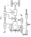
- a motor vehicle MV comprises a power transmission unit including a power propulsion system PWT and a transmission system T.
- the power propulsion system PWT includes an internal combustion engine ICE and a reversible electric machine EM.
- the power propulsion system may also comprise one or more auxiliary devices AUX, for example including an air conditioning system compressor.
- the electric motor EM and the auxiliary components AUX are connected to the internal combustion engine ICE through a belt transmission B including a belt and a plurality of pulleys P1, P2, P3 and a belt-stretching device (not illustrated, which can be of any known type).
- the pulley P3 is mounted on the output shaft of the electric machine EM, which constitutes a BAS unit adapted to operate as an alternator, for generating electrical power, when it is driven by the internal combustion engine, as a starter for starting the internal combustion engine, and as an electric motor for actuating auxiliary devices AUX. Furthermore, as indicated hereinafter, the machine EM can also be used, in given operating conditions, as the only propulsion engine of the vehicle.
- the pulley P2 is mounted on the upstream end of the internal combustion engine shaft ICE, while one or more pulleys P1 (only one of which is illustrated) is mounted on the shaft of each auxiliary device, if required by interposing an engagement device, which allows decoupling the auxiliary device from the belt transmission.
- the system of pulleys P1, P2, P3 and the transmission belt B are capable of transmitting the propulsion torque produced by the electric machine to the shaft of the engine ICE and to the auxiliary components AUX and vice versa transmitting the propulsion torque produced by the engine ICE to the electric machine EM and to the auxiliary components AUX through the internal combustion engine.
- the power propulsion system PWT includes two electrical sections V1, V2 with different voltages to which there are respectively connected two accumulators ACC1, ACC2, auxiliary electric loads and a DC-DC voltage converter capable of bidirectionally controlling the energy exchange between the two sections.
- the power propulsion system further includes an inverter INV for the power control of the electric machine EM.
- the transmission line T comprises a gearbox G of the electric, or electrohydraulic, or electromechanical type, with discrete ratios, of the of the gear type, having an input shaft that can be coupled to the drive shaft CS through an engagement and one or more clutches C and an output shaft or coupled to a pair of drive wheels W through a differential D of any known type.
- the clutch C which can be single or double, is servo-controlled through an associated actuator CA with electric or electrohydraulic control.
- the gearbox G is servo-controlled through a plurality of actuators with electric or electrohydraulic or electromechanical control, indicated in its entirety with GA, which can be operated to perform the engagement and the disengagement of the gears corresponding to the different obtainable gear ratios.
- the internal combustion engine ICE is controlled by an electronic control unit E-ECU of the per se known type and thus not described in detail, while the inverter INV of the electric machine EM is controlled by an electronic control unit EM-ECU.
- the power transmission unit PWT includes three electronic control units (PWT-ECU, E-ECU and EM-ECU) capable of respectively controlling the transmission line alongside the gearbox unit, the internal combustion engine and the electric machine EM.
- the aforementioned electronic control units exchange messages through a network CAN.
- FIG. 2 illustrates, by way of example, a simplified variant in which the gearbox G is of the conventional type, controlled manually.
- Figure 3 and figure 4 of the attached drawings refer to an example of an internal combustion engine of the known type provided with the MULTIAIR system developed by the applicant, for the variable actuation of the intake valves.
- Figure 1 illustrates in particular a sectional view of a cylinder head of a four-cylinder internal combustion engine.
- the cylinder head indicated in its entirety with reference number 1, comprises, for each cylinder, a cavity 2 formed on the lower surface thereof 3 defining the combustion chamber, in which two intake conduits 4 (only one of which is shown in the figure) and two exhaust conduits (not shown in the figure) terminate.
- the communication of the two intake conduits to the combustion chamber 2 is controlled by two intake valves 5 (only one of which is shown in the figure) each comprising a stem 6 slidably mounted in the body of the head 1.
- Each valve 6 is returned towards the closing position by a spring 7 interposed between an inner surface of the head 1 and an end cup of the valve.
- the communication of the two exhaust conduits to the combustion chamber is controlled by two valves of the conventional type (not shown in the figure) to which there is also associated springs for return towards the closed position.
- each intake valve 6 is controlled, as described hereinafter, by a camshaft 8 mounted rotatably around an axis 9 within supports (not shown in the figure) of the head 1, and comprising a plurality of cams 10 for the actuation of the intake valves 5.
- Each cam 10 cooperates with a tappet 11 which in the case of the illustrated example is constituted by an arm oscillatably mounted at an end 12 thereof on the structure of the head cylinders and having a central portion thereof which rotatably freely supports a roller 13 cooperating with the cam 10.
- the opposite end 14 of the oscillating arm 11 controls a pumping piston 15 through a plate 16 connected to the piston 15. The latter is returned by a spring 17 against the arm 11, so as to maintain the arm 11 in cooperation contact with the cam 10.
- the pumping piston 15 is slidably mounted in a cavity which is obtained in a preassembled block 18 which is mounted on the head 1 and which incorporates all the electrical and hydraulic devices part of the system for variable actuation of the intake valves the engine is provided with, according to what is described in detail hereinafter.
- the pumping piston 15 is capable of transmitting a thrust to the stem 6 of each intake valve 5, so as to cause the opening of the latter against the action of the spring 9, through a pressurised fluid (preferably oil coming from the engine lubrication circuit) present in a pressure chamber C to which the pumping piston 15 is faced. Following the thrust applied by the pumping piston 15, the pressurised oil is transferred from the chamber C to the chamber of a hydraulic actuator 19 whose piston 20 pushes the valve 5 towards the open position.
- a pressurised fluid preferably oil coming from the engine lubrication circuit
- figure 4 shows a schematic representation of the system illustrated in figure 3 .
- the pressurised fluid chamber C associated to the intake valves 5 of each cylinder may be placed in communication with an exhaust channel 21 through a solenoid valve 22 controlled by a programmable electronic control unit 23.
- the solenoid valve 22 which can be of any known type, suitable for the function illustrated herein, is controlled by the control unit 23 as a function of signals S indicating engine operation parameters, such as the position of the accelerator and the number of engine revolutions.
- the chamber C When the solenoid valve 22 is open, the chamber C enters in communication, through a channel 24 and a circumferential chamber 25 ( figure 2 ) with the exhaust channel 21. hence the pressurised fluid present in the chamber C flows in such channel and there is obtained a decoupling of the cam 10 and the tappet 7 with respect to the intake valves 5, which thus quickly return in the closing position thereof, under the action of the return springs 9, should they be in the open condition, corresponding to a phase in which the tappet 11 is in contact with the lobe of the cam 10.
- the exhaust channel 21 communicates, according to a solution previously proposed by the applicant, with a tank 26, vented at the upper part with respect to the atmosphere in 27.
- the tank 26 in turn communicates through a conduit 28 with an accumulator of pressurised fluid 29 (schematically illustrated in the figure 2 ).
- the exhaust tank 26 communicates with a conduit 30 connected to the engine lubrication circuit through a conduit 31 in which there is interposed a check-valve 32 which allows the fluid to flow only in the direction of the tank 26.
- the engine exhaust valves are controlled conventionally, through a respective camshaft and a mechanical transmission.
- the exhaust valves can also not be excluded that the exhaust valves be controlled variably, having a system of the type described above for the intake valves.
- the solenoid valve 22 In the engine operation, should the solenoid valve 22 be maintained closed, the chamber C remains full of pressurised fluid and the movements of the cam 10 are transmitted to the intake valves 5 according to a lift profile which corresponds to the cam profile 10.
- the control unit 23 is however programmed to connect the chamber C to discharge in given engine operating conditions with the aim of causing the closing of the intake valves even when the cam 10 would tend to keep them open.
- varying the opening time (as the duration of the opening, as time of start and time of end of the opening) and/or lift of the intake valves at will, for example to obtain a delayed opening and/or advance closing or to obtain a plurality of openings and closings within the conventional intake valves opening phase, according to the description subject of the previous patents of the applicant.
- the actuator 20 is further provided with hydraulic braking means which slow the final closing travel of the intake valve 5 when the latter closes following an opening of the solenoid valve 22, so as to avoid an excessive impact and an ensuing damaging of the intake valve upon reaching the closed position.
- the hydraulic braking means are not described herein, in that they can be obtained in any one of the methods known from the previous patent documents of the applicant.
- the vehicle in both embodiments it is provided for that, in given operating conditions, the vehicle be solely operated by the electric machine EM ("e-motoring" condition).
- the internal combustion engine ICE is off, i.e. moved to a cut-off condition.
- the pistons of the engine ICE move due to the rotation of the drive shaft, which serves as a simple transmission shaft between the pulley P2 which receives the motion from the electric machine EM through the belt transmission B, and the transmission system T, connecting the output end of the drive shaft CS to the wheels W of the motor vehicle.
- the system according to the invention is capable reducing the pumping losses due to the movement of the pistons in the engine cylinders, due to the fact that the internal combustion engine ICE is provided with a system for variable actuation of the intake valves.
- the system for variable actuation that the engine ICE is provided with is the MULTIAIR system developed by the applicant, which was described above with reference to the attached figures 3 , 4 .
- the pumping losses of the engine are reduced closing the intake valve in advance, according to the valve lift scheme illustrated in figure 5 , where the profile A is the lift profile of each intake valve determined by the profile of the respective cam, while the profile A1 shows an example of valve control with closing in advance, obtainable by connecting the respective pressure chamber to discharge in advance with respect to the normal closing determined by the cam profile.
- the system is also capable of further reducing the losses due to the pumping effect during the e-motoring phase, causing a supplementary opening of the intake valves during the phase theoretically corresponding to the conventional exhaust phase.
- the use of the MULTIAIR system for obtaining an additional opening of the intake valves during the conventional exhaust phase is per se known for example from the previous document EP-A-1 936 132 of the applicant.
- the cams for the actuation of the intake valves of the engine each have, as shown in figure 4 , a profile comprising a main portion 10a for causing the opening of the intake valve during the conventional intake phase in the respective cylinder of the engine and an additional portion 10b for causing a partial opening of the intake valves even during the conventional exhaust phase in the respective cylinder.
- Figure 6 of the attached drawings shows a diagram which represents the lift profiles of the intake valve and the exhaust valve of an engine cylinder thus obtained.
- the profile A is that regarding the lift of the intake valve
- the profile B is that regarding the exhaust valve.
- the diagram shows the lift in mm as a function of the crank angle.
- the 180° crank angle corresponds to the condition in which the piston is at the Bottom Dead Centre, at the beginning of the exhaust phase in the cylinder.
- the 360° angle corresponds to the condition in which the piston has reached the Top Dead Centre, at the end of the exhaust phase and at the beginning of the subsequent intake phase, which theoretically terminates at a crank angle equivalent to 540°, where the piston is once again positioned at the Bottom Dead Centre.
- the profile A has a main portion A1 (having the conventional bell-like shape) which causes the opening of the valve during the normal intake phase in the cylinder and an additional portion A2, which causes an additional lift of the intake valve during the exhaust phase.
- the additional profile A2 substantially extends starting from an angle equivalent to 180° (Bottom Dead Centre), at the beginning of the exhaust phase, with a first ascending section "a” connected with a second section "b” with substantially constant lift, equivalent to a fraction of the maximum lift achieved by the intake valve during the intake phase.
- the sections A1 and A2 of the lift profile A of the intake valve are determined by the corresponding cam profile 10 ( figure 4 ), having the main portion 10a corresponding to the portion A1 of the lift profile and the additional portion 10b corresponding to the portion A2 of the lift profile.
- the control maintains the pressure chamber associated to each intake valve at the profile 10b of the cam.
- the opening of the intake valves during the theoretical exhaust phase allows sending in the intake conduit of each cylinder part of the exhaust gases previously formed in the last engine operating cycle, immediately before the cut-off required to obtain the e-motoring condition.
- Suitably controlling the opening and the closing of the intake valves, and maintaining the closed exhaust valves thus allows such amount of exhaust gas to move alternatingly between the combustion chamber of each cylinder and the respective intake conduit. This allows avoiding introducing comburent and fuel into each cylinder, hence the pumping losses are minimised.
- said system for variable actuation of the intake valves be controlled so as to differently actuate intake valves associated to different cylinders or so as to differently actuate the same intake valve over time, as a function of the engine operating conditions, which are detected by the electronic control unit through a plurality of sensors.
- the e-motoring condition is activated, according to such embodiment, in a condition in which the motor vehicle is stationary, to execute an "e-launch" strategy, i.e. a vehicle start in stationary condition using the electric propulsion alone and with the internal combustion engine off and driven by the BAS unit.
- an "e-launch" strategy i.e. a vehicle start in stationary condition using the electric propulsion alone and with the internal combustion engine off and driven by the BAS unit.
- Entry in the e-motoring condition with the vehicle moving is actuated in case of specific conditions of the vehicle (for example covering road sections with constant power delivered to the ground), the internal combustion engine (for example operation in low efficiency conditions), the electrical system (for example accumulators ACC1 and ACC2 with suitable charge conditions).
- specific conditions of the vehicle for example covering road sections with constant power delivered to the ground
- the internal combustion engine for example operation in low efficiency conditions
- the electrical system for example accumulators ACC1 and ACC2 with suitable charge conditions.
- the acceleration of the switching off is obtained by temporarily increasing (instead of reducing) the pumping losses of the internal combustion engine, by controlling the system for variable actuation of the intake valves such to cause a delayed opening (see line A2 in figure 5 ), or a total absence of opening of the intake valves.
- control logic of the intake valves of the internal combustion engine may be allocated in any of the aforementioned electronic control units. It is automatically activated on the basis of any input, preferably selected from among the following:
- the main characteristic of the present invention which can be applied both on a hybrid vehicle of the type described above and in a conventional vehicle, provided with the internal combustion engine alone, regards the aforementioned phase of operation with the vehicle moving and internal combustion engine in cut-off condition.
- the system for variable actuation of the intake valves is controlled to vary the opening time and/or closing time and/or the lift of the intake valves so as to control the losses due to the pumping effect which occur within the engine in said cut-off condition, according to one of the following strategies:
- the system for variable actuation of the intake valves is also controlled to reduce the pumping losses in the phase in which the internal combustion engine is started through an electric start motor.
- the management of the vehicle coast-down with an internal combustion engine in cut-off can be carried out through an optimised management of the intelligent alternator logic (regulation of the alternator regulator set-point).
Landscapes
- Engineering & Computer Science (AREA)
- Mechanical Engineering (AREA)
- General Engineering & Computer Science (AREA)
- Chemical & Material Sciences (AREA)
- Combustion & Propulsion (AREA)
- Output Control And Ontrol Of Special Type Engine (AREA)
- Valve Device For Special Equipments (AREA)
Abstract
If the engine is equipped with starter capable of starting while engine moving, pumping losses are minimised to increase engine run down time. If the engine is equipped with starter capable of starting only engine at still stand, pumping loss are minimised as long as RPM is above threshold to allow restart by fuel supply and pumping losses are maximised when RPM is below threshold to reach quick stand still for restart by electric starter. This insures quick restart in case of driver change of mind in any case.
Description
- The present invention regards a method for controlling a motor vehicle provided with an internal combustion engine having a system for variable actuation of the intake valves.
- The main object of the present invention is to exploit the system for variable actuation of the intake valves of the internal combustion engine to obtain more efficient operating modes of the vehicle, in particular with reference to an operating mode with the vehicle moving and engine in cut-off condition, as well as for example even with reference to the phase for starting the engine. A further object is to exploit the aforementioned system to increase the efficiency of an e-motoring operating mode, i.e. the electric propulsion alone, in a hybrid vehicle provided with an electric motor kinematically arranged upstream of the internal combustion engine.
- With the aim of attaining the aforementioned main object, the invention aims at providing a method for controlling a motor vehicle provided with an internal combustion engine having a system for variable actuation of the intake valves, characterised in that said method comprises a phase of activation of an operating mode with the engine off and the vehicle moving, in which the fuel supply to the engine is cut-off, and in that after the cut-off of fuel supply the to the engine the system for variable actuation of the intake valves is controlled to vary the opening time and/or closing time and/or the lift of the intake valves so as to control the losses due to the pumping effect which occur within the engine in said cut-off condition, according to one of the following strategies:
- if the speed of the engine is above the minimum-run threshold, the intake valves are controlled so as to temporarily minimise the pumping losses, to increase the engine run-down time, so as to allow a possible change-of-mind of the driver, and a restart of the engine by reactivating the fuel supply;
- if the speed of the engine is below the minimum-run threshold one of the following strategies are actuated:
- if the motor vehicle is provided with an electric start motor capable of operating with the internal combustion engine moving, the intake valves are controlled so as to temporarily minimise the pumping losses to increase the run-down time, i.e. the time required to reach the stop of the drive shaft, so as to be able to restart the internal combustion engine when it is still moving;
- if the motor vehicle is provided with an electric start motor capable of operating only when the internal combustion engine is stationary, the intake valves are controlled so as to temporarily maximise the pumping losses to reduce the engine run-down time, with the aim of allowing a possible engine restart with the engine stationary as soon as possible.
- According to a further preferred characteristic of the invention, the system for variable actuation of the intake valves is also controlled to reduce the pumping losses in the phase in which the internal combustion engine is started through an electric start motor.
- According to the invention, the increase of the pumping losses of the internal combustion engine is obtained by controlling the system for variable actuation of the intake valves such to cause a delayed opening of the intake valves with respect to a conventional intake cycle, or a total absence of opening of the intake valves.
- The reduction of the pumping losses of the internal combustion engine is obtained by controlling the system for variable actuation of the intake valves such to cause a closing of the intake valves in advance with respect to a conventional intake cycle.
- Preferably, with the aim reducing the aforementioned pumping losses to the minimum, said system for variable actuation of the intake valves is controlled so as to open the intake valves during a phase which - during the normal operation of the engine - corresponds to the exhaust phase, with the aim of obtaining a recirculation - in each cylinder - of the exhaust gases produced in the engine immediately before the cut-off phase.
- In the preferred embodiment, the internal combustion engine is provided having a system for variable actuation of the engine valves of the type developed under the MULTIAIR trademark by the applicant (see for example
EP-A-1 936 132 ). Such system comprises at least one camshaft connected to the drive shaft, and it is of the type in which each intake valve is controlled by a respective tappet actuated by a respective cam of said camshaft, against the action of spring means associated to each intake valve which return the intake valve towards a closed position, and in which said tappet is connected to said intake valve through hydraulic actuation means, comprising a pressure hydraulic chamber which can be connected to an exhaust channel through an electronic control solenoid valve, so as to uncouple the intake valve from the respective cam and cause the closing thereof due to said return spring means.. - According to a further characteristic of the invention, said system for variable actuation of the intake valves is controlled so as to differently actuate intake valves associated to different cylinders and/or so as to differently actuate the same intake valve over time as a function of the engine operating conditions, detected by an electronic control unit through a plurality of sensors.
- In an embodiment, the vehicle is provided, additionally to the internal combustion engine, with an electric motor kinematically connected to the internal combustion engine, upstream of the internal combustion engine, i.e. with the internal combustion engine kinematically interposed between the electric motor and the driven wheels of the vehicle and there is provided for an e-motoring phase in which the electric motor is used as the only motor vehicle propulsion engine, with the internal combustion engine in cut-off condition, and in that in such e-motoring phase the system for variable actuation of the intake valves is controlled to reduce the pumping losses of the engine.
- Further characteristics and advantages of the invention will be apparent from the following description with reference to the attached drawings, provided purely by way of non-limiting example, wherein:
-
figure 1 illustrates a block diagram of a power propulsion system of a motor vehicle of the "mild-hybrid" type, according to an embodiment of the present invention, -
figure 2 illustrates a simplified variant of the system of thefigure 1 , -
figures 3 ,4 are a sectional view and a corresponding schematic view of an internal combustion engine provided with the MULTIAIR system developed by the applicant, as illustrated for example inEP-A-1 936 132 , and -
figures 5, 6 are diagrams showing the lift profiles of the intake valves of the internal combustion engine in two different embodiments of the invention. - Though the preferred embodiment illustrated herein refers to a hybrid vehicle, provided with an internal combustion engine and an electric propulsion engine, the principles of the invention can also be applied to a conventional vehicle, solely provided with an internal combustion engine.
- With reference to
figure 1 , a motor vehicle MV comprises a power transmission unit including a power propulsion system PWT and a transmission system T. The power propulsion system PWT includes an internal combustion engine ICE and a reversible electric machine EM. the power propulsion system may also comprise one or more auxiliary devices AUX, for example including an air conditioning system compressor. The electric motor EM and the auxiliary components AUX are connected to the internal combustion engine ICE through a belt transmission B including a belt and a plurality of pulleys P1, P2, P3 and a belt-stretching device (not illustrated, which can be of any known type). The pulley P3 is mounted on the output shaft of the electric machine EM, which constitutes a BAS unit adapted to operate as an alternator, for generating electrical power, when it is driven by the internal combustion engine, as a starter for starting the internal combustion engine, and as an electric motor for actuating auxiliary devices AUX. Furthermore, as indicated hereinafter, the machine EM can also be used, in given operating conditions, as the only propulsion engine of the vehicle. The pulley P2 is mounted on the upstream end of the internal combustion engine shaft ICE, while one or more pulleys P1 (only one of which is illustrated) is mounted on the shaft of each auxiliary device, if required by interposing an engagement device, which allows decoupling the auxiliary device from the belt transmission. As indicated, the system of pulleys P1, P2, P3 and the transmission belt B are capable of transmitting the propulsion torque produced by the electric machine to the shaft of the engine ICE and to the auxiliary components AUX and vice versa transmitting the propulsion torque produced by the engine ICE to the electric machine EM and to the auxiliary components AUX through the internal combustion engine. the power propulsion system PWT includes two electrical sections V1, V2 with different voltages to which there are respectively connected two accumulators ACC1, ACC2, auxiliary electric loads and a DC-DC voltage converter capable of bidirectionally controlling the energy exchange between the two sections. the power propulsion system further includes an inverter INV for the power control of the electric machine EM. - The transmission line T comprises a gearbox G of the electric, or electrohydraulic, or electromechanical type, with discrete ratios, of the of the gear type, having an input shaft that can be coupled to the drive shaft CS through an engagement and one or more clutches C and an output shaft or coupled to a pair of drive wheels W through a differential D of any known type. The clutch C, which can be single or double, is servo-controlled through an associated actuator CA with electric or electrohydraulic control. Also the gearbox G is servo-controlled through a plurality of actuators with electric or electrohydraulic or electromechanical control, indicated in its entirety with GA, which can be operated to perform the engagement and the disengagement of the gears corresponding to the different obtainable gear ratios.
- The internal combustion engine ICE is controlled by an electronic control unit E-ECU of the per se known type and thus not described in detail, while the inverter INV of the electric machine EM is controlled by an electronic control unit EM-ECU. therefore the power transmission unit PWT includes three electronic control units (PWT-ECU, E-ECU and EM-ECU) capable of respectively controlling the transmission line alongside the gearbox unit, the internal combustion engine and the electric machine EM. The aforementioned electronic control units exchange messages through a network CAN.
-
Figure 2 illustrates, by way of example, a simplified variant in which the gearbox G is of the conventional type, controlled manually. -
Figure 3 andfigure 4 of the attached drawings refer to an example of an internal combustion engine of the known type provided with the MULTIAIR system developed by the applicant, for the variable actuation of the intake valves.Figure 1 illustrates in particular a sectional view of a cylinder head of a four-cylinder internal combustion engine. - With reference to
figure 3 , the cylinder head, indicated in its entirety withreference number 1, comprises, for each cylinder, acavity 2 formed on the lower surface thereof 3 defining the combustion chamber, in which two intake conduits 4 (only one of which is shown in the figure) and two exhaust conduits (not shown in the figure) terminate. The communication of the two intake conduits to thecombustion chamber 2 is controlled by two intake valves 5 (only one of which is shown in the figure) each comprising astem 6 slidably mounted in the body of thehead 1. Eachvalve 6 is returned towards the closing position by aspring 7 interposed between an inner surface of thehead 1 and an end cup of the valve. The communication of the two exhaust conduits to the combustion chamber is controlled by two valves of the conventional type (not shown in the figure) to which there is also associated springs for return towards the closed position. - The opening of each
intake valve 6 is controlled, as described hereinafter, by acamshaft 8 mounted rotatably around anaxis 9 within supports (not shown in the figure) of thehead 1, and comprising a plurality ofcams 10 for the actuation of theintake valves 5. - Each
cam 10 cooperates with atappet 11 which in the case of the illustrated example is constituted by an arm oscillatably mounted at anend 12 thereof on the structure of the head cylinders and having a central portion thereof which rotatably freely supports aroller 13 cooperating with thecam 10. theopposite end 14 of the oscillatingarm 11 controls apumping piston 15 through aplate 16 connected to thepiston 15. The latter is returned by aspring 17 against thearm 11, so as to maintain thearm 11 in cooperation contact with thecam 10. Thepumping piston 15 is slidably mounted in a cavity which is obtained in a preassembledblock 18 which is mounted on thehead 1 and which incorporates all the electrical and hydraulic devices part of the system for variable actuation of the intake valves the engine is provided with, according to what is described in detail hereinafter. - The
pumping piston 15 is capable of transmitting a thrust to thestem 6 of eachintake valve 5, so as to cause the opening of the latter against the action of thespring 9, through a pressurised fluid (preferably oil coming from the engine lubrication circuit) present in a pressure chamber C to which thepumping piston 15 is faced. Following the thrust applied by thepumping piston 15, the pressurised oil is transferred from the chamber C to the chamber of ahydraulic actuator 19 whosepiston 20 pushes thevalve 5 towards the open position. - All the previously described parts are also shown in
figure 4 , which shows a schematic representation of the system illustrated infigure 3 . - With reference to both
figures 3 ,4 , the pressurised fluid chamber C associated to theintake valves 5 of each cylinder may be placed in communication with anexhaust channel 21 through asolenoid valve 22 controlled by a programmableelectronic control unit 23. thesolenoid valve 22, which can be of any known type, suitable for the function illustrated herein, is controlled by thecontrol unit 23 as a function of signals S indicating engine operation parameters, such as the position of the accelerator and the number of engine revolutions. - When the
solenoid valve 22 is open, the chamber C enters in communication, through achannel 24 and a circumferential chamber 25 (figure 2 ) with theexhaust channel 21. hence the pressurised fluid present in the chamber C flows in such channel and there is obtained a decoupling of thecam 10 and thetappet 7 with respect to theintake valves 5, which thus quickly return in the closing position thereof, under the action of thereturn springs 9, should they be in the open condition, corresponding to a phase in which thetappet 11 is in contact with the lobe of thecam 10. - The
exhaust channel 21 communicates, according to a solution previously proposed by the applicant, with atank 26, vented at the upper part with respect to the atmosphere in 27. Thetank 26 in turn communicates through aconduit 28 with an accumulator of pressurised fluid 29 (schematically illustrated in thefigure 2 ). - Lastly, the
exhaust tank 26 communicates with aconduit 30 connected to the engine lubrication circuit through aconduit 31 in which there is interposed a check-valve 32 which allows the fluid to flow only in the direction of thetank 26. - In the illustrated example, the engine exhaust valves are controlled conventionally, through a respective camshaft and a mechanical transmission. However, according to the invention, it can also not be excluded that the exhaust valves be controlled variably, having a system of the type described above for the intake valves.
- In the engine operation, should the
solenoid valve 22 be maintained closed, the chamber C remains full of pressurised fluid and the movements of thecam 10 are transmitted to theintake valves 5 according to a lift profile which corresponds to thecam profile 10. Thecontrol unit 23 is however programmed to connect the chamber C to discharge in given engine operating conditions with the aim of causing the closing of the intake valves even when thecam 10 would tend to keep them open. Thus, such solution allows varying the opening time (as the duration of the opening, as time of start and time of end of the opening) and/or lift of the intake valves at will, for example to obtain a delayed opening and/or advance closing or to obtain a plurality of openings and closings within the conventional intake valves opening phase, according to the description subject of the previous patents of the applicant. - Still with reference to
figure 3 , it should be observed that theactuator 20 is further provided with hydraulic braking means which slow the final closing travel of theintake valve 5 when the latter closes following an opening of thesolenoid valve 22, so as to avoid an excessive impact and an ensuing damaging of the intake valve upon reaching the closed position. The hydraulic braking means are not described herein, in that they can be obtained in any one of the methods known from the previous patent documents of the applicant. - Returning to the systems illustrated in
figures 1 and2 , in both embodiments it is provided for that, in given operating conditions, the vehicle be solely operated by the electric machine EM ("e-motoring" condition). - In such operating condition, the internal combustion engine ICE is off, i.e. moved to a cut-off condition. In such condition, the pistons of the engine ICE move due to the rotation of the drive shaft, which serves as a simple transmission shaft between the pulley P2 which receives the motion from the electric machine EM through the belt transmission B, and the transmission system T, connecting the output end of the drive shaft CS to the wheels W of the motor vehicle.
- In such operating condition, the system according to the invention is capable reducing the pumping losses due to the movement of the pistons in the engine cylinders, due to the fact that the internal combustion engine ICE is provided with a system for variable actuation of the intake valves.
- As previously indicated, preferably the system for variable actuation that the engine ICE is provided with is the MULTIAIR system developed by the applicant, which was described above with reference to the attached
figures 3 ,4 . - According to a first solution, in the "e-monitoring" phases in which the vehicle is solely operated by the electric machine EM, the pumping losses of the engine are reduced closing the intake valve in advance, according to the valve lift scheme illustrated in
figure 5 , where the profile A is the lift profile of each intake valve determined by the profile of the respective cam, while the profile A1 shows an example of valve control with closing in advance, obtainable by connecting the respective pressure chamber to discharge in advance with respect to the normal closing determined by the cam profile. - In a particularly preferred variant of the invention, which is described herein with reference to
figure 6 , the system is also capable of further reducing the losses due to the pumping effect during the e-motoring phase, causing a supplementary opening of the intake valves during the phase theoretically corresponding to the conventional exhaust phase. the use of the MULTIAIR system for obtaining an additional opening of the intake valves during the conventional exhaust phase is per se known for example from the previous documentEP-A-1 936 132 of the applicant. - In the case of the preferred embodiment of the present invention, the cams for the actuation of the intake valves of the engine each have, as shown in
figure 4 , a profile comprising amain portion 10a for causing the opening of the intake valve during the conventional intake phase in the respective cylinder of the engine and anadditional portion 10b for causing a partial opening of the intake valves even during the conventional exhaust phase in the respective cylinder. -
Figure 6 of the attached drawings shows a diagram which represents the lift profiles of the intake valve and the exhaust valve of an engine cylinder thus obtained. - In such figure, the profile A is that regarding the lift of the intake valve, and the profile B is that regarding the exhaust valve. the diagram shows the lift in mm as a function of the crank angle. In the convention assumed in the diagrams of
figures 5 and 6 , the 180° crank angle corresponds to the condition in which the piston is at the Bottom Dead Centre, at the beginning of the exhaust phase in the cylinder. The 360° angle corresponds to the condition in which the piston has reached the Top Dead Centre, at the end of the exhaust phase and at the beginning of the subsequent intake phase, which theoretically terminates at a crank angle equivalent to 540°, where the piston is once again positioned at the Bottom Dead Centre. As observable infigure 6 , the profile A has a main portion A1 (having the conventional bell-like shape) which causes the opening of the valve during the normal intake phase in the cylinder and an additional portion A2, which causes an additional lift of the intake valve during the exhaust phase. the additional profile A2 substantially extends starting from an angle equivalent to 180° (Bottom Dead Centre), at the beginning of the exhaust phase, with a first ascending section "a" connected with a second section "b" with substantially constant lift, equivalent to a fraction of the maximum lift achieved by the intake valve during the intake phase. The sections A1 and A2 of the lift profile A of the intake valve are determined by the corresponding cam profile 10 (figure 4 ), having themain portion 10a corresponding to the portion A1 of the lift profile and theadditional portion 10b corresponding to the portion A2 of the lift profile. - With the cams profiled as illustrated in
figure 4 , should one intend to cause the supplementary opening of the intake valve during the theoretical exhaust phase, it is sufficient that the control maintains the pressure chamber associated to each intake valve at theprofile 10b of the cam. the opening of the intake valves during the theoretical exhaust phase allows sending in the intake conduit of each cylinder part of the exhaust gases previously formed in the last engine operating cycle, immediately before the cut-off required to obtain the e-motoring condition. Suitably controlling the opening and the closing of the intake valves, and maintaining the closed exhaust valves, thus allows such amount of exhaust gas to move alternatingly between the combustion chamber of each cylinder and the respective intake conduit. This allows avoiding introducing comburent and fuel into each cylinder, hence the pumping losses are minimised. - Obviously it is preferable to adopt both solutions described above, i.e. both the additional opening of the intake valves in the exhaust phase (
fig 6 ), and the closing of the intake valves in advance during the conventional intake phase (fig.5 ) - According to a further solution, in such embodiment it is provided for that said system for variable actuation of the intake valves be controlled so as to differently actuate intake valves associated to different cylinders or so as to differently actuate the same intake valve over time, as a function of the engine operating conditions, which are detected by the electronic control unit through a plurality of sensors.
- The e-motoring condition is activated, according to such embodiment, in a condition in which the motor vehicle is stationary, to execute an "e-launch" strategy, i.e. a vehicle start in stationary condition using the electric propulsion alone and with the internal combustion engine off and driven by the BAS unit.
- Entry in the e-motoring condition with the vehicle moving is actuated in case of specific conditions of the vehicle (for example covering road sections with constant power delivered to the ground), the internal combustion engine (for example operation in low efficiency conditions), the electrical system (for example accumulators ACC1 and ACC2 with suitable charge conditions).
- Still in case of such embodiment, when the aforementioned e-motoring operating condition is activated, the switching off of the engine is accelerated, with the aim of being able to promptly restart it in case of a change-of-mind of the driver.
- According to the invention, the acceleration of the switching off is obtained by temporarily increasing (instead of reducing) the pumping losses of the internal combustion engine, by controlling the system for variable actuation of the intake valves such to cause a delayed opening (see line A2 in
figure 5 ), or a total absence of opening of the intake valves. - According to the invention, the control logic of the intake valves of the internal combustion engine may be allocated in any of the aforementioned electronic control units. It is automatically activated on the basis of any input, preferably selected from among the following:
- accelerator pedal position signal;
- brake pedal position signal;
- clutch condition signal (both for manual and robotized gearboxes);
- signal indicating the speed of the vehicle;
- signal indicating the engaged gear, in case of a robotized gearbox, or engagement of a neutral gear for manual gears.
- The system described above allows providing the following operating modes:
- gear with torque supply from the internal combustion engine alone (accelerator pressed, brake released, clutch closed, non-zero speed): the intake valves of the internal combustion engine are controlled so as to optimise the combustion efficiency, according to the conventional use of the MULTIAIR system;
- gear with torque supply from the electric motor alone (e-motoring) in which the internal combustion engine is driven by the electric motor or it is in deceleration phase for cut-off (accelerator released, brake released, clutch closed, non-zero speed): in such conditions the intake valves of the engine are controlled so as to minimise the pumping losses (
figures 5, 6 ), so as to minimise the deceleration of the vehicle, while the fuel injection is temporarily inhibited to minimise fuel consumption; - freewheel operating mode, with an internal combustion engine off and the wheels of the vehicle not connected to the power propulsion system: during the freewheel operation, two situations may occur with the internal combustion engine in run-down mode:
- speed of the internal combustion engine above the minimum-run threshold: in this situation the intake valves are controlled so as to temporarily minimise the pumping losses to increase the engine run-down time, to allow a possible freewheel output with fuel re-injection (thus avoiding a BAS or starter engine start, if a starter is also provided for besides the BAS, i.e. an electric start motor);
- speed of the engine below the minimum-run threshold: in this situation the following strategies may be actuated:
- the intake valves are controlled so as to temporarily minimise the pumping losses to increase the engine run-down time to prepare to restart the engine (in case of change-of-mind of the driver) by engaging the clutch ("clutch pulse", only in case of automatic gearbox) or through BAS ('BAS cranking') or through a starter ('starter cranking') of the type capable of restarting the engine even at non-zero engine speed;
- the intake valves are controlled so as to temporarily maximise the pumping losses to reduce the engine run-down time with the aim of allowing a possible engine restart through a conventional starter as soon as possible, if it is not possible to perform a clutch restart given that the gearbox is manual, or through BAS;
- phase for starting the internal combustion engine (accelerator released, brake released, clutch open, zero speed): the intake valves of the engine are controlled so as to minimise the pumping losses (
figures 5, 6 ) for minimising the time for starting the internal combustion engine, using the electric machine EM as a starter. - The main characteristic of the present invention, which can be applied both on a hybrid vehicle of the type described above and in a conventional vehicle, provided with the internal combustion engine alone, regards the aforementioned phase of operation with the vehicle moving and internal combustion engine in cut-off condition. In such condition, according to the main characteristic of the invention, the system for variable actuation of the intake valves is controlled to vary the opening time and/or closing time and/or the lift of the intake valves so as to control the losses due to the pumping effect which occur within the engine in said cut-off condition, according to one of the following strategies:
- if the speed of the engine is above the minimum-run threshold, the intake valves are controlled so as to temporarily minimise the pumping losses, to increase the engine run-down time, so as to allow a possible change-of-mind of the driver, and a restart of the engine by reactivating the fuel supply;
- if the speed of the engine is below the minimum-run threshold one of the following strategies are actuated:
- if the motor vehicle is provided with an electric start motor capable of operating with the internal combustion engine moving, the intake valves are controlled so as to temporarily minimise the pumping losses to increase the run-down time, i.e. the time required to reach the stop of the drive shaft, so as to be able to restart the internal combustion engine when it is still moving;
- if the motor vehicle is provided with an electric start motor capable of operating only when the internal combustion engine is stationary, the intake valves are controlled so as to temporarily maximise the pumping losses to reduce the engine run-down time, with the aim of allowing a possible engine restart with the engine stationary as soon as possible.
- Preferably, the system for variable actuation of the intake valves is also controlled to reduce the pumping losses in the phase in which the internal combustion engine is started through an electric start motor.
- In the case of a conventional vehicle, the management of the vehicle coast-down with an internal combustion engine in cut-off can be carried out through an optimised management of the intelligent alternator logic (regulation of the alternator regulator set-point).
- Obviously, without prejudice to the principle of the invention, the construction details and the embodiments may widely vary with respect to what has been described and illustrated purely by way of example, without departing from the scope of protection of the present invention.
Claims (8)
- Method for controlling a motor vehicle provided with an internal combustion engine having a system for variable actuation of the intake valves,
characterised in that said method comprises a phase of activation of an operating mode with the engine off and the vehicle moving, in which the fuel supply to the engine is cut-off,
and in that after the cut-off of the fuel supply to the engine the system for variable actuation of the intake valves is controlled to vary the opening time and/or closing time and/or the lift of the intake valves so as to control the losses due to a pumping effect which occur within the engine in said cut-off condition, according to one of the following strategies:- if the speed of the engine is above the minimum-run threshold, the intake valves are controlled so as to temporarily minimise the pumping losses, to increase the engine run-down time, so as to allow a possible change-of-mind of the driver, and a restart of the engine by reactivating the fuel supply;- if the speed of the engine is below the minimum-run threshold one of the following strategies are actuated:- if the motor vehicle is provided with an electric start motor capable of operating with the internal combustion engine moving, the intake valves are controlled so as to temporarily minimise the pumping losses to increase the run-down time, i.e. the time required to reach the stop of the drive shaft, so as to be able to restart the internal combustion engine when it is still moving;- if the motor vehicle is provided with an electric start motor capable of operating only when the internal combustion engine is stationary, the intake valves are controlled so as to temporarily maximise the pumping losses to reduce the engine run-down time, with the aim of allowing a possible engine restart, with the engine stationary, as soon as possible. - Method according to claim 1, characterised in that the system for variable actuation of the intake valves is also controlled to reduce the pumping losses in the phase in which the internal combustion engine is started through an electric start motor.
- Method according to claim 1 or 2, in which the internal combustion engine is provided with a system for variable actuation of the engine valves comprising at least one camshaft (10) connected to the drive shaft, in which each intake valve (5) is controlled by a respective tappet (11) actuated by a respective cam (10) of said camshaft, against the action of spring means (7) associated to each intake valve which return the intake valve towards a closed position, and in which said tappet (11) is connected to said intake valve (5) through hydraulic actuation means, comprising a pressure hydraulic chamber (C) which can be connected to an exhaust channel (21) through an electronically controlled solenoid valve (22), so as to uncouple the intake valve (5) from the respective cam (10) and cause the closing thereof due to said return spring means(7).
- Method according to any one of the preceding claims, characterised in that said system for variable actuation of the intake valves is controlled so as to differently actuate intake valves associated to different cylinders and/or so as to differently actuate the same intake valve over time as a function of the engine operating conditions, detected by an electronic control unit through a plurality of sensors.
- Method according to any one of the preceding claims, characterised in that said vehicle is provided, additionally to the internal combustion engine, with an electric motor kinematically connected to the internal combustion engine, upstream of the internal combustion engine, i.e. with the internal combustion engine kinematically interposed between the electric motor and the driven wheels of the vehicle and in that there is provided an e-motoring phase in which the electric motor is used as the only motor vehicle propulsion engine, with the internal combustion engine in cut-off condition, and in that in such e-motoring phase the system for variable actuation of the intake valves is controlled to reduce the pumping losses of the engine.
- Method according to claim 1, characterised in that the increase of the pumping losses of the internal combustion engine is obtained by controlling the system for variable actuation of the intake valves such to cause a delayed opening of the intake valves with respect to a conventional intake cycle, or a total absence of opening of the intake valves.
- Method according to claim 1, characterised in that the reduction of the pumping losses of the internal combustion engine is obtained by controlling the system for variable actuation of the intake valves such to cause a closing of the intake valves in advance with respect to a conventional intake cycle.
- Method according to claim 7, characterised in that said system for variable actuation of the intake valves is controlled so as to open the intake valves (5) during a phase which - during the normal operation of the engine - corresponds to the exhaust phase, with the aim of obtaining a recirculation - in each cylinder - of the exhaust gases produced in the engine immediately before the cut-off phase.
Priority Applications (4)
| Application Number | Priority Date | Filing Date | Title |
|---|---|---|---|
| EP11183663.1A EP2578871B1 (en) | 2011-10-03 | 2011-10-03 | Method for controlling a motor-vehicle provided with an internal combustion engine having a system for variable actuation of the intake valves |
| PCT/IB2012/053430 WO2013050887A1 (en) | 2011-10-03 | 2012-07-05 | Method for controlling a motor vehicle provided with an internal combustion engine having a system for variable actuation of the intake valves |
| US14/241,688 US9429080B2 (en) | 2011-10-03 | 2012-07-05 | Method for controlling a motor-vehicle provided with an internal combustion engine having a system for variable actuation of the intake valves |
| BR112014008005-4A BR112014008005B1 (en) | 2011-10-03 | 2012-07-05 | METHOD FOR CONTROLLING AN AUTOMOTIVE VEHICLE WITH AN INTERNAL COMBUSTION ENGINE PRESENTING A SYSTEM FOR VARIABLE ACTION OF THE INLET VALVES |
Applications Claiming Priority (1)
| Application Number | Priority Date | Filing Date | Title |
|---|---|---|---|
| EP11183663.1A EP2578871B1 (en) | 2011-10-03 | 2011-10-03 | Method for controlling a motor-vehicle provided with an internal combustion engine having a system for variable actuation of the intake valves |
Publications (2)
| Publication Number | Publication Date |
|---|---|
| EP2578871A1 true EP2578871A1 (en) | 2013-04-10 |
| EP2578871B1 EP2578871B1 (en) | 2016-09-21 |
Family
ID=46640083
Family Applications (1)
| Application Number | Title | Priority Date | Filing Date |
|---|---|---|---|
| EP11183663.1A Active EP2578871B1 (en) | 2011-10-03 | 2011-10-03 | Method for controlling a motor-vehicle provided with an internal combustion engine having a system for variable actuation of the intake valves |
Country Status (4)
| Country | Link |
|---|---|
| US (1) | US9429080B2 (en) |
| EP (1) | EP2578871B1 (en) |
| BR (1) | BR112014008005B1 (en) |
| WO (1) | WO2013050887A1 (en) |
Cited By (11)
| Publication number | Priority date | Publication date | Assignee | Title |
|---|---|---|---|---|
| FR3038006A1 (en) * | 2015-06-26 | 2016-12-30 | Gerard Mesplie | METHOD AND SYSTEM FOR SUSPENDING A COMBUSTION ENGINE WITHOUT STOPPING ITS ROTATION |
| WO2017097900A1 (en) * | 2015-12-10 | 2017-06-15 | Bayerische Motoren Werke Aktiengesellschaft | Method for starting an internal combustion engine |
| FR3045107A1 (en) * | 2015-12-14 | 2017-06-16 | Peugeot Citroen Automobiles Sa | METHOD FOR MINIMIZING PUMPING LOSSES IN A THERMAL ENGINE DURING STARTING |
| WO2018065011A1 (en) * | 2016-10-05 | 2018-04-12 | Schaeffler Technologies AG & Co. KG | Hydraulic gas exchange valve train comprising a damper chamber connected to a pressure chamber by a throttle |
| EP3318748A3 (en) * | 2016-11-02 | 2018-06-27 | Paccar Inc | Intermittent restart for automatic engine stop start system |
| DE102017009269A1 (en) * | 2017-10-06 | 2019-04-11 | Daimler Ag | Method for starting an internal combustion engine, in particular a hybrid drive, and internal combustion engine, in particular a hybrid drive, and internal combustion engine, in particular for carrying out the method |
| US10451022B2 (en) | 2016-11-02 | 2019-10-22 | Paccar Inc | Intermittent restart for automatic engine stop start system |
| US10487762B2 (en) | 2017-09-26 | 2019-11-26 | Paccar Inc | Systems and methods for predictive and automatic engine stop-start control |
| US10690103B2 (en) | 2017-09-26 | 2020-06-23 | Paccar Inc | Systems and methods for using an electric motor in predictive and automatic engine stop-start systems |
| US10746255B2 (en) | 2018-05-09 | 2020-08-18 | Paccar Inc | Systems and methods for reducing noise, vibration, and/or harshness during engine shutdown and restart |
| US10883566B2 (en) | 2018-05-09 | 2021-01-05 | Paccar Inc | Systems and methods for reducing noise, vibration and/or harshness associated with cylinder deactivation in internal combustion engines |
Families Citing this family (5)
| Publication number | Priority date | Publication date | Assignee | Title |
|---|---|---|---|---|
| GB2486709B (en) * | 2010-12-23 | 2017-10-11 | Jaguar Land Rover Ltd | Hybrid electric vehicle controller and method of controlling a hybrid electric vehicle |
| KR101449323B1 (en) * | 2013-08-29 | 2014-10-08 | 현대자동차주식회사 | Device and method for controlling clutch of hybrid vehicle |
| US8977422B1 (en) * | 2013-11-06 | 2015-03-10 | The Goodyear Tire & Rubber Company | Accoustic/vibration sensor and tire assembly and method of construction thereof |
| US10329969B2 (en) | 2014-11-10 | 2019-06-25 | Jacobs Vehicle Systems, Inc. | System and method of adjusting actuation timing of valves in a piston engine |
| KR20160064847A (en) * | 2014-11-28 | 2016-06-08 | 현대자동차주식회사 | Continuous varible vavle duration apparatus and control method by using the same |
Citations (5)
| Publication number | Priority date | Publication date | Assignee | Title |
|---|---|---|---|---|
| EP1936132A1 (en) | 2006-12-20 | 2008-06-25 | C.R.F. Societa' Consortile per Azioni | Internal combustion engine with intake valves having a variable actuation and a lift profile including a constant lift boot portion |
| WO2008110910A1 (en) * | 2007-02-06 | 2008-09-18 | Toyota Jidosha Kabushiki Kaisha | Control apparatus for a multiple cylinder internal combustion engine |
| JP2010071205A (en) * | 2008-09-19 | 2010-04-02 | Nissan Motor Co Ltd | Control device of internal combustion engine |
| US20100114461A1 (en) * | 2008-11-06 | 2010-05-06 | Ford Global Technologies, Llc | Engine shutdown control |
| US20100305820A1 (en) * | 2009-05-28 | 2010-12-02 | Mcgee Ryan A | Engine Speed Reduction Preparatory to an Engine Restart |
Family Cites Families (3)
| Publication number | Priority date | Publication date | Assignee | Title |
|---|---|---|---|---|
| JP3381613B2 (en) * | 1998-03-20 | 2003-03-04 | 日産自動車株式会社 | Drive control device for hybrid vehicle |
| US6053134A (en) * | 1998-08-28 | 2000-04-25 | Linebarger; Terry Glyn | Cam operating system |
| JP3719339B2 (en) * | 1998-11-09 | 2005-11-24 | 日産自動車株式会社 | Variable valve controller for internal combustion engine |
-
2011
- 2011-10-03 EP EP11183663.1A patent/EP2578871B1/en active Active
-
2012
- 2012-07-05 WO PCT/IB2012/053430 patent/WO2013050887A1/en not_active Ceased
- 2012-07-05 BR BR112014008005-4A patent/BR112014008005B1/en active IP Right Grant
- 2012-07-05 US US14/241,688 patent/US9429080B2/en active Active
Patent Citations (5)
| Publication number | Priority date | Publication date | Assignee | Title |
|---|---|---|---|---|
| EP1936132A1 (en) | 2006-12-20 | 2008-06-25 | C.R.F. Societa' Consortile per Azioni | Internal combustion engine with intake valves having a variable actuation and a lift profile including a constant lift boot portion |
| WO2008110910A1 (en) * | 2007-02-06 | 2008-09-18 | Toyota Jidosha Kabushiki Kaisha | Control apparatus for a multiple cylinder internal combustion engine |
| JP2010071205A (en) * | 2008-09-19 | 2010-04-02 | Nissan Motor Co Ltd | Control device of internal combustion engine |
| US20100114461A1 (en) * | 2008-11-06 | 2010-05-06 | Ford Global Technologies, Llc | Engine shutdown control |
| US20100305820A1 (en) * | 2009-05-28 | 2010-12-02 | Mcgee Ryan A | Engine Speed Reduction Preparatory to an Engine Restart |
Cited By (15)
| Publication number | Priority date | Publication date | Assignee | Title |
|---|---|---|---|---|
| FR3038006A1 (en) * | 2015-06-26 | 2016-12-30 | Gerard Mesplie | METHOD AND SYSTEM FOR SUSPENDING A COMBUSTION ENGINE WITHOUT STOPPING ITS ROTATION |
| WO2017097900A1 (en) * | 2015-12-10 | 2017-06-15 | Bayerische Motoren Werke Aktiengesellschaft | Method for starting an internal combustion engine |
| FR3045107A1 (en) * | 2015-12-14 | 2017-06-16 | Peugeot Citroen Automobiles Sa | METHOD FOR MINIMIZING PUMPING LOSSES IN A THERMAL ENGINE DURING STARTING |
| WO2018065011A1 (en) * | 2016-10-05 | 2018-04-12 | Schaeffler Technologies AG & Co. KG | Hydraulic gas exchange valve train comprising a damper chamber connected to a pressure chamber by a throttle |
| EP3318748A3 (en) * | 2016-11-02 | 2018-06-27 | Paccar Inc | Intermittent restart for automatic engine stop start system |
| US11421640B2 (en) | 2016-11-02 | 2022-08-23 | Paccar Inc. | Intermittent restart for automatic engine stop start system |
| US10934988B2 (en) | 2016-11-02 | 2021-03-02 | Paccar Inc | Intermittent restart for automatic engine stop start system |
| US10451022B2 (en) | 2016-11-02 | 2019-10-22 | Paccar Inc | Intermittent restart for automatic engine stop start system |
| US10690103B2 (en) | 2017-09-26 | 2020-06-23 | Paccar Inc | Systems and methods for using an electric motor in predictive and automatic engine stop-start systems |
| US10487762B2 (en) | 2017-09-26 | 2019-11-26 | Paccar Inc | Systems and methods for predictive and automatic engine stop-start control |
| US11105286B2 (en) | 2017-09-26 | 2021-08-31 | Paccar Inc | Systems and methods for predictive and automatic engine stop-start control |
| DE102017009269A8 (en) * | 2017-10-06 | 2019-06-19 | Daimler Ag | Method for starting an internal combustion engine, in particular a hybrid drive, and internal combustion engine, in particular for carrying out the method |
| DE102017009269A1 (en) * | 2017-10-06 | 2019-04-11 | Daimler Ag | Method for starting an internal combustion engine, in particular a hybrid drive, and internal combustion engine, in particular a hybrid drive, and internal combustion engine, in particular for carrying out the method |
| US10746255B2 (en) | 2018-05-09 | 2020-08-18 | Paccar Inc | Systems and methods for reducing noise, vibration, and/or harshness during engine shutdown and restart |
| US10883566B2 (en) | 2018-05-09 | 2021-01-05 | Paccar Inc | Systems and methods for reducing noise, vibration and/or harshness associated with cylinder deactivation in internal combustion engines |
Also Published As
| Publication number | Publication date |
|---|---|
| BR112014008005A2 (en) | 2017-04-11 |
| EP2578871B1 (en) | 2016-09-21 |
| US20140202423A1 (en) | 2014-07-24 |
| WO2013050887A1 (en) | 2013-04-11 |
| BR112014008005B1 (en) | 2021-08-03 |
| US9429080B2 (en) | 2016-08-30 |
Similar Documents
| Publication | Publication Date | Title |
|---|---|---|
| EP2578871B1 (en) | Method for controlling a motor-vehicle provided with an internal combustion engine having a system for variable actuation of the intake valves | |
| EP2578462B1 (en) | Method for controlling a motor-vehicle provided with a propulsion system of the "mild-hybrid" type | |
| US10106162B2 (en) | Methods and system for starting an engine | |
| US20080041323A1 (en) | Atkinson Cycle Powertrain | |
| US6545372B2 (en) | Hybrid motor for a vehicle | |
| CN101234638A (en) | Hybrid vehicle with engine power cylinder deactivation | |
| US11285960B2 (en) | Method for operating a vehicle having a disconnect clutch | |
| US10857993B2 (en) | Methods and system activating a vehicle | |
| CA2899875A1 (en) | Control system of a gaseous fueled engine with a cam phaser for improving the engine start | |
| US10384665B1 (en) | Methods and system for starting an engine | |
| CN111741883B (en) | Method for controlling powertrain system during upshift | |
| US11458828B2 (en) | Method for controlling an internal combustion engine of a hybrid powertrain | |
| KR101431294B1 (en) | Hybrid drive with valve deactivation | |
| US11940023B2 (en) | System and method for driveline disconnect clutch de-stroking and prepositioning | |
| EP4074945B1 (en) | System for actuation of an intake valve of an internal combustion engine | |
| US12090992B2 (en) | Driveline disconnect clutch operating methods and system | |
| US10605221B2 (en) | Methods and system for positioning an engine for starting | |
| US11661914B2 (en) | Methods and system for starting an engine | |
| CN203221878U (en) | Independent type automatic switching hybrid power transmission case | |
| US12270351B2 (en) | Reversing method for a vehicle powertrain | |
| US11597374B2 (en) | Methods and system for arbitrating fuel cut out for a hybrid vehicle | |
| US9371785B2 (en) | Vehicle and method of operating | |
| KR101568189B1 (en) | Method for actuating valve for improving fuel efficiency in coasting and apparatus for controlling valve |
Legal Events
| Date | Code | Title | Description |
|---|---|---|---|
| PUAI | Public reference made under article 153(3) epc to a published international application that has entered the european phase |
Free format text: ORIGINAL CODE: 0009012 |
|
| 17P | Request for examination filed |
Effective date: 20120613 |
|
| AK | Designated contracting states |
Kind code of ref document: A1 Designated state(s): AL AT BE BG CH CY CZ DE DK EE ES FI FR GB GR HR HU IE IS IT LI LT LU LV MC MK MT NL NO PL PT RO RS SE SI SK SM TR |
|
| AX | Request for extension of the european patent |
Extension state: BA ME |
|
| GRAP | Despatch of communication of intention to grant a patent |
Free format text: ORIGINAL CODE: EPIDOSNIGR1 |
|
| INTG | Intention to grant announced |
Effective date: 20160602 |
|
| GRAS | Grant fee paid |
Free format text: ORIGINAL CODE: EPIDOSNIGR3 |
|
| GRAA | (expected) grant |
Free format text: ORIGINAL CODE: 0009210 |
|
| REG | Reference to a national code |
Ref country code: FR Ref legal event code: PLFP Year of fee payment: 6 |
|
| AK | Designated contracting states |
Kind code of ref document: B1 Designated state(s): AL AT BE BG CH CY CZ DE DK EE ES FI FR GB GR HR HU IE IS IT LI LT LU LV MC MK MT NL NO PL PT RO RS SE SI SK SM TR |
|
| REG | Reference to a national code |
Ref country code: GB Ref legal event code: FG4D |
|
| REG | Reference to a national code |
Ref country code: CH Ref legal event code: EP |
|
| REG | Reference to a national code |
Ref country code: AT Ref legal event code: REF Ref document number: 831269 Country of ref document: AT Kind code of ref document: T Effective date: 20161015 |
|
| REG | Reference to a national code |
Ref country code: IE Ref legal event code: FG4D |
|
| REG | Reference to a national code |
Ref country code: DE Ref legal event code: R096 Ref document number: 602011030515 Country of ref document: DE |
|
| REG | Reference to a national code |
Ref country code: LT Ref legal event code: MG4D Ref country code: NL Ref legal event code: MP Effective date: 20160921 |
|
| PG25 | Lapsed in a contracting state [announced via postgrant information from national office to epo] |
Ref country code: LT Free format text: LAPSE BECAUSE OF FAILURE TO SUBMIT A TRANSLATION OF THE DESCRIPTION OR TO PAY THE FEE WITHIN THE PRESCRIBED TIME-LIMIT Effective date: 20160921 Ref country code: RS Free format text: LAPSE BECAUSE OF FAILURE TO SUBMIT A TRANSLATION OF THE DESCRIPTION OR TO PAY THE FEE WITHIN THE PRESCRIBED TIME-LIMIT Effective date: 20160921 Ref country code: FI Free format text: LAPSE BECAUSE OF FAILURE TO SUBMIT A TRANSLATION OF THE DESCRIPTION OR TO PAY THE FEE WITHIN THE PRESCRIBED TIME-LIMIT Effective date: 20160921 Ref country code: NO Free format text: LAPSE BECAUSE OF FAILURE TO SUBMIT A TRANSLATION OF THE DESCRIPTION OR TO PAY THE FEE WITHIN THE PRESCRIBED TIME-LIMIT Effective date: 20161221 |
|
| REG | Reference to a national code |
Ref country code: AT Ref legal event code: MK05 Ref document number: 831269 Country of ref document: AT Kind code of ref document: T Effective date: 20160921 |
|
| PG25 | Lapsed in a contracting state [announced via postgrant information from national office to epo] |
Ref country code: GR Free format text: LAPSE BECAUSE OF FAILURE TO SUBMIT A TRANSLATION OF THE DESCRIPTION OR TO PAY THE FEE WITHIN THE PRESCRIBED TIME-LIMIT Effective date: 20161222 Ref country code: NL Free format text: LAPSE BECAUSE OF FAILURE TO SUBMIT A TRANSLATION OF THE DESCRIPTION OR TO PAY THE FEE WITHIN THE PRESCRIBED TIME-LIMIT Effective date: 20160921 Ref country code: BE Free format text: LAPSE BECAUSE OF NON-PAYMENT OF DUE FEES Effective date: 20161031 Ref country code: LV Free format text: LAPSE BECAUSE OF FAILURE TO SUBMIT A TRANSLATION OF THE DESCRIPTION OR TO PAY THE FEE WITHIN THE PRESCRIBED TIME-LIMIT Effective date: 20160921 Ref country code: SE Free format text: LAPSE BECAUSE OF FAILURE TO SUBMIT A TRANSLATION OF THE DESCRIPTION OR TO PAY THE FEE WITHIN THE PRESCRIBED TIME-LIMIT Effective date: 20160921 |
|
| PG25 | Lapsed in a contracting state [announced via postgrant information from national office to epo] |
Ref country code: RO Free format text: LAPSE BECAUSE OF FAILURE TO SUBMIT A TRANSLATION OF THE DESCRIPTION OR TO PAY THE FEE WITHIN THE PRESCRIBED TIME-LIMIT Effective date: 20160921 Ref country code: EE Free format text: LAPSE BECAUSE OF FAILURE TO SUBMIT A TRANSLATION OF THE DESCRIPTION OR TO PAY THE FEE WITHIN THE PRESCRIBED TIME-LIMIT Effective date: 20160921 |
|
| PG25 | Lapsed in a contracting state [announced via postgrant information from national office to epo] |
Ref country code: SM Free format text: LAPSE BECAUSE OF FAILURE TO SUBMIT A TRANSLATION OF THE DESCRIPTION OR TO PAY THE FEE WITHIN THE PRESCRIBED TIME-LIMIT Effective date: 20160921 Ref country code: CZ Free format text: LAPSE BECAUSE OF FAILURE TO SUBMIT A TRANSLATION OF THE DESCRIPTION OR TO PAY THE FEE WITHIN THE PRESCRIBED TIME-LIMIT Effective date: 20160921 Ref country code: AT Free format text: LAPSE BECAUSE OF FAILURE TO SUBMIT A TRANSLATION OF THE DESCRIPTION OR TO PAY THE FEE WITHIN THE PRESCRIBED TIME-LIMIT Effective date: 20160921 Ref country code: PT Free format text: LAPSE BECAUSE OF FAILURE TO SUBMIT A TRANSLATION OF THE DESCRIPTION OR TO PAY THE FEE WITHIN THE PRESCRIBED TIME-LIMIT Effective date: 20170123 Ref country code: BG Free format text: LAPSE BECAUSE OF FAILURE TO SUBMIT A TRANSLATION OF THE DESCRIPTION OR TO PAY THE FEE WITHIN THE PRESCRIBED TIME-LIMIT Effective date: 20161221 Ref country code: ES Free format text: LAPSE BECAUSE OF FAILURE TO SUBMIT A TRANSLATION OF THE DESCRIPTION OR TO PAY THE FEE WITHIN THE PRESCRIBED TIME-LIMIT Effective date: 20160921 Ref country code: PL Free format text: LAPSE BECAUSE OF FAILURE TO SUBMIT A TRANSLATION OF THE DESCRIPTION OR TO PAY THE FEE WITHIN THE PRESCRIBED TIME-LIMIT Effective date: 20160921 Ref country code: BE Free format text: LAPSE BECAUSE OF FAILURE TO SUBMIT A TRANSLATION OF THE DESCRIPTION OR TO PAY THE FEE WITHIN THE PRESCRIBED TIME-LIMIT Effective date: 20160921 Ref country code: SK Free format text: LAPSE BECAUSE OF FAILURE TO SUBMIT A TRANSLATION OF THE DESCRIPTION OR TO PAY THE FEE WITHIN THE PRESCRIBED TIME-LIMIT Effective date: 20160921 Ref country code: IS Free format text: LAPSE BECAUSE OF FAILURE TO SUBMIT A TRANSLATION OF THE DESCRIPTION OR TO PAY THE FEE WITHIN THE PRESCRIBED TIME-LIMIT Effective date: 20170121 |
|
| REG | Reference to a national code |
Ref country code: CH Ref legal event code: PL |
|
| REG | Reference to a national code |
Ref country code: DE Ref legal event code: R097 Ref document number: 602011030515 Country of ref document: DE |
|
| REG | Reference to a national code |
Ref country code: IE Ref legal event code: MM4A |
|
| PLBE | No opposition filed within time limit |
Free format text: ORIGINAL CODE: 0009261 |
|
| STAA | Information on the status of an ep patent application or granted ep patent |
Free format text: STATUS: NO OPPOSITION FILED WITHIN TIME LIMIT |
|
| PG25 | Lapsed in a contracting state [announced via postgrant information from national office to epo] |
Ref country code: CH Free format text: LAPSE BECAUSE OF NON-PAYMENT OF DUE FEES Effective date: 20161031 Ref country code: LI Free format text: LAPSE BECAUSE OF NON-PAYMENT OF DUE FEES Effective date: 20161031 Ref country code: DK Free format text: LAPSE BECAUSE OF FAILURE TO SUBMIT A TRANSLATION OF THE DESCRIPTION OR TO PAY THE FEE WITHIN THE PRESCRIBED TIME-LIMIT Effective date: 20160921 |
|
| GBPC | Gb: european patent ceased through non-payment of renewal fee |
Effective date: 20161221 |
|
| 26N | No opposition filed |
Effective date: 20170622 |
|
| PG25 | Lapsed in a contracting state [announced via postgrant information from national office to epo] |
Ref country code: LU Free format text: LAPSE BECAUSE OF NON-PAYMENT OF DUE FEES Effective date: 20161003 |
|
| REG | Reference to a national code |
Ref country code: FR Ref legal event code: PLFP Year of fee payment: 7 |
|
| PG25 | Lapsed in a contracting state [announced via postgrant information from national office to epo] |
Ref country code: GB Free format text: LAPSE BECAUSE OF NON-PAYMENT OF DUE FEES Effective date: 20161221 Ref country code: IE Free format text: LAPSE BECAUSE OF NON-PAYMENT OF DUE FEES Effective date: 20161003 Ref country code: SI Free format text: LAPSE BECAUSE OF FAILURE TO SUBMIT A TRANSLATION OF THE DESCRIPTION OR TO PAY THE FEE WITHIN THE PRESCRIBED TIME-LIMIT Effective date: 20160921 |
|
| PG25 | Lapsed in a contracting state [announced via postgrant information from national office to epo] |
Ref country code: CY Free format text: LAPSE BECAUSE OF FAILURE TO SUBMIT A TRANSLATION OF THE DESCRIPTION OR TO PAY THE FEE WITHIN THE PRESCRIBED TIME-LIMIT Effective date: 20160921 Ref country code: HU Free format text: LAPSE BECAUSE OF FAILURE TO SUBMIT A TRANSLATION OF THE DESCRIPTION OR TO PAY THE FEE WITHIN THE PRESCRIBED TIME-LIMIT; INVALID AB INITIO Effective date: 20111003 |
|
| PG25 | Lapsed in a contracting state [announced via postgrant information from national office to epo] |
Ref country code: MK Free format text: LAPSE BECAUSE OF FAILURE TO SUBMIT A TRANSLATION OF THE DESCRIPTION OR TO PAY THE FEE WITHIN THE PRESCRIBED TIME-LIMIT Effective date: 20160921 Ref country code: TR Free format text: LAPSE BECAUSE OF FAILURE TO SUBMIT A TRANSLATION OF THE DESCRIPTION OR TO PAY THE FEE WITHIN THE PRESCRIBED TIME-LIMIT Effective date: 20160921 Ref country code: MT Free format text: LAPSE BECAUSE OF NON-PAYMENT OF DUE FEES Effective date: 20161031 Ref country code: MC Free format text: LAPSE BECAUSE OF FAILURE TO SUBMIT A TRANSLATION OF THE DESCRIPTION OR TO PAY THE FEE WITHIN THE PRESCRIBED TIME-LIMIT Effective date: 20160921 Ref country code: HR Free format text: LAPSE BECAUSE OF FAILURE TO SUBMIT A TRANSLATION OF THE DESCRIPTION OR TO PAY THE FEE WITHIN THE PRESCRIBED TIME-LIMIT Effective date: 20160921 |
|
| REG | Reference to a national code |
Ref country code: FR Ref legal event code: PLFP Year of fee payment: 8 |
|
| PG25 | Lapsed in a contracting state [announced via postgrant information from national office to epo] |
Ref country code: AL Free format text: LAPSE BECAUSE OF FAILURE TO SUBMIT A TRANSLATION OF THE DESCRIPTION OR TO PAY THE FEE WITHIN THE PRESCRIBED TIME-LIMIT Effective date: 20160921 |
|
| PGFP | Annual fee paid to national office [announced via postgrant information from national office to epo] |
Ref country code: IT Payment date: 20250923 Year of fee payment: 15 |
|
| PGFP | Annual fee paid to national office [announced via postgrant information from national office to epo] |
Ref country code: FR Payment date: 20250925 Year of fee payment: 15 |
|
| PGFP | Annual fee paid to national office [announced via postgrant information from national office to epo] |
Ref country code: DE Payment date: 20250923 Year of fee payment: 15 |