EP2578764A1 - A roof window with a barrel bolt and such a barrel bolt - Google Patents
A roof window with a barrel bolt and such a barrel bolt Download PDFInfo
- Publication number
- EP2578764A1 EP2578764A1 EP12187167.7A EP12187167A EP2578764A1 EP 2578764 A1 EP2578764 A1 EP 2578764A1 EP 12187167 A EP12187167 A EP 12187167A EP 2578764 A1 EP2578764 A1 EP 2578764A1
- Authority
- EP
- European Patent Office
- Prior art keywords
- bolt
- housing
- sash
- roof window
- barrel bolt
- Prior art date
- Legal status (The legal status is an assumption and is not a legal conclusion. Google has not performed a legal analysis and makes no representation as to the accuracy of the status listed.)
- Granted
Links
Images


Classifications
-
- E—FIXED CONSTRUCTIONS
- E04—BUILDING
- E04D—ROOF COVERINGS; SKY-LIGHTS; GUTTERS; ROOF-WORKING TOOLS
- E04D13/00—Special arrangements or devices in connection with roof coverings; Protection against birds; Roof drainage ; Sky-lights
- E04D13/03—Sky-lights; Domes; Ventilating sky-lights
- E04D13/035—Sky-lights; Domes; Ventilating sky-lights characterised by having movable parts
- E04D13/0351—Sky-lights; Domes; Ventilating sky-lights characterised by having movable parts the parts pivoting about a fixed axis
- E04D13/0354—Sky-lights; Domes; Ventilating sky-lights characterised by having movable parts the parts pivoting about a fixed axis the parts being flat
-
- E—FIXED CONSTRUCTIONS
- E05—LOCKS; KEYS; WINDOW OR DOOR FITTINGS; SAFES
- E05C—BOLTS OR FASTENING DEVICES FOR WINGS, SPECIALLY FOR DOORS OR WINDOWS
- E05C1/00—Fastening devices with bolts moving rectilinearly
- E05C1/02—Fastening devices with bolts moving rectilinearly without latching action
- E05C1/04—Fastening devices with bolts moving rectilinearly without latching action with operating handle or equivalent member rigid with the bolt
Definitions
- the present invention relates to a roof window comprising a frame with a top member, a bottom member and two side members defining a frame plane, and a sash having a top member, a bottom member and two side members defining a sash plane, the roof window further comprising, in connection with the sash top member, a top sash module, the roof window furthermore comprising at least one barrel bolt adapted for releasably locking the sash to the frame in a position of the roof window in which the sash is rotated to a position outside its normal opening range, preferably close to 180 degrees, about a pivot hinge axis with respect to the frame, the barrel bolt comprising a housing and a bolt arranged in the housing in such a way as to be longitudinally displaceable in relation to the housing, the barrel bolt furthermore comprising an operating means.
- the present invention furthermore relates to such a barrel bolt.
- this and other objects are achieved with a roof window of the above kind, where the operating means has an angle with respect to the bolt such that it extends substantially in the direction of a depth axis of the window, and a length such that it terminates approximately level with the surface of the top sash module facing away from the housing of the barrel bolt.
- a roof window is provided with which the barrel bolt is easy and straightforward to reach and thereby to operate when the user desires to fix the window in a position allowing cleaning of the outside surface of the pane from the inside of a building.
- a barrel bolt for releasably locking a sash of a roof window to a frame of the roof window in a position of the roof window in which the sash is rotated approximately to 180 degrees around a pivot hinge axis with respect to the frame
- the barrel bolt comprising a housing and a bolt arranged in the housing in such a way as to be longitudinally displaceable in a telescopic manner within the housing, and an operating means, wherein the operating means of the barrel bolt extends at an angle, preferably at a right angle, with respect to the longitudinal direction of the bolt, and has a length of between 1 and 3 cm.
- the chosen angle and range of the length makes it possible to attain the easy operation aimed at while still providing for an aesthetically acceptable appearance.
- Fig. 1 and Fig. 2 show one embodiment of a window 1 according to the invention comprising a pane 4 defining plane 16, a frame 2 having a top member 5, a bottom member 6 and two side members 7, 8 defining a frame plane, and a sash 3 having a top member 9, a bottom member 10 and two side members 11, 12 defining a sash plane.
- the window is centre-hung in that the sash 3 is connected to the frame 2 by a pivot hinge (not shown) provided between side members 7, 11; 8, 12 of the frame 2 and sash 3, respectively, to be openable by tilting the sash 3 of the window 1 about the pivot hinge axis 21 defined by the pivot hinge.
- the pivot hinge comprises two parts, namely a sash part and a frame part.
- the hinges used are preferably of the type described in the applicant's earlier patent applications WO9928581 and GB1028251 , where a curved member and a tap on one hinge parts travels in a curved guide track in the other during opening and closing of the window.
- the radius of curvature entails that when using such hinges, the hinge axis lies at a small distance above the actual hinge parts and as the sash frame is turned first the curved member and then the tap comes out of the track. In combination this provides a pattern of movement which allows easy operation of a centre-hung window and allows the sash frame to be turned substantially entirely around.
- a closed position of the window 1 means a position in which the frame plane and the sash plane coincide, that is form an angle of 0 degrees with each other.
- an open position of the window 1 as used herein generally means a position in which the sash 3 is tilted about the pivot hinge axis 21 such that the frame plane and the sash plane no longer coincide.
- a longitudinal axis 13 of the window 1 is defined as extending perpendicular to and between the frame top member 5 and the frame bottom member 6
- a transversal axis 14 of the window is defined as extending perpendicular to and between the respective frame side members 7 and 8 and thereby perpendicular to the longitudinal axis 13
- a depth axis 15 of the window 1 is defined as extending perpendicular to both the longitudinal axis 13 and the transversal axis 14.
- the pivot hinge axis 21 and the transversal axis 14 are parallel, and are shown as coinciding in the figures.
- the window 1 furthermore comprises a lock 17 of a type known per se for locking the frame 2 and sash 3 together as well as a generally circumferentially extending sealing 18 provided on the sash 3 for sealing the gap between the sash 3 and the frame 2 in the closed position of the window 1.
- the sealing 18 comprises at least one, preferably at least two sealing strips.
- the window according to the invention may in other embodiments be top-hung, with or without an intermediate frame structure, have the hinge axis somewhere between the top and the centre, be side-hung or for that matter even be bottom-hung.
- the sash 3 and frame 2 of the window according to the invention may be made of wooden members or members made of cast or extruded polyurethane (PUR).
- PUR polyurethane
- the window 1 comprises in connection with the top member 9 of the sash 3 a top sash module 411 and a ventilation flap 400.
- the top sash module 411 has a substantially rectangular cross section with a first side 412, a second side 415 opposite to and extending parallel with said first side 411, a third side 413 and a fourth side 414 opposite to and extending parallel with said third side 413.
- the third and fourth sides 413 and 414 extend substantially perpendicular to and connecting said first and second sides 412 and 415.
- the first side 412 of the top sash module 411 is adapted to be attached to or abutting a surface of the top sash member 9 opposite the pane 4 of the window 1.
- the side sash members 11 and 12 of the window 1 each comprise an extension 417, respectively 416, extending in the longitudinal direction 13 of the window 1 beyond the top sash member 9.
- the third and fourth sides 413 and 414 are connected to the extensions 416, respectively 417, of the side sash members 12, respectively 11. In this way the top sash module 411 is placed essentially outside the area delimited by the sash structure 3, i.e. essentially outside the sash plane.
- connection between the third side 413 and the extension 416, respectively the fourth side 414 and the extension 417 may be achieved in any suitable way, such as by a friction-locking or snap-locking mechanism or even by means of an adhesive or an attachment means such as a screw or a nail.
- the third and fourth side 413 and 414 are each provided with an attachment member 435, respectively 438, while the extensions 416 and 417 are each provided with a corresponding receiving member 437, respectively 439.
- the attachment members 435 and 438 are protrusions provided with a slot 436, respectively 440, while the receiving members 437 and 439 are corresponding slots in the extensions 416 and 417.
- the slots 436, 440 provide the attachment members 435 and 438 with a spring-effect such that the attachment members 435 and 438 are retained in the receiving members 437 and 439 by means of friction.
- Such an arrangement provides for a particularly secure and strong attachment of the top sash module 411.
- the top sash module 411 is furthermore provided with one or more ventilation openings 418.
- air is allowed to pass through the ventilation openings 418 when the ventilation flap 400 is in its open position, while the ventilation openings 418 are closed when the ventilation flap 400 is in its closed position abutting the top sash module 411.
- the amount of air passing the ventilation openings 418 may be regulated by means of the intermediate positions of the ventilation flap 400.
- the sash module 411 forms a sealing stop for the ventilation flap 400.
- the top sash module 411 may furthermore be provided with at least one, preferably two, protrusions 434, which are arranged in connection with a ventilation opening 418.
- the protrusion(s) 434 is intended for acting as a guide means for an element 406' connecting the pivot connection 406 and the lock 17.
- This arrangement has the advantage compared with the known solutions, that the ventilation arrangement provided by the top sash module 411 and the ventilation flap 400 in combination is positioned essentially outside the plane defined by the sash members 9, 10, 11, 12.
- the top sash module 411 and the ventilation flap 400 are positioned in such a way as to enable the area available for the pane 4 to be increased, which in turn allows for more light to be transmitted through the window into a building in which it is installed.
- this arrangement may increase the pane area by 8 to 9 %, particularly about 8 %.
- Another advantage provided with this arrangement lies in that the top casing 500 may be made smaller, which in turn saves material and thus provides for a window 1 which is cheaper to manufacture.
- top sash module 411 may be adapted to function as a holder for receiving a gasket or sealing strip for sealing the gap between the top sash module 411 and the top frame member 5 in the closed position of the window 1.
- the second side 415 of the top sash module may be provided with a recess or groove 419 extending substantially in the total longitudinal extension of the top sash module 411.
- the recess 419 is arranged such as to be flush with a corresponding recess or groove in the respective adjacent extensions 416 and 417 of the side sash members 11 and 12 in the mounted position of the top sash module 411, such as to enable providing the window 1 with a preferably circumferentially extending sealing 18 for sealing the gap between the sash 3 and the frame 2 in the closed position of the window 1.
- the window furthermore comprises at least one barrel bolt 420 comprising a housing 421 with a first, preferably open, end 427 and a second, preferably closed, end 428, and a bolt 422 arranged in the housing 421 in such a way as to be longitudinally displaceable in relation to the housing 421 from a first position in which the bolt 422 is placed completely within the housing 421 (cf. Fig. 5 ) to a second position in which the bolt 422 is placed at least partially outside the housing 422.
- a barrel bolt 420 comprising a housing 421 with a first, preferably open, end 427 and a second, preferably closed, end 428, and a bolt 422 arranged in the housing 421 in such a way as to be longitudinally displaceable in relation to the housing 421 from a first position in which the bolt 422 is placed completely within the housing 421 (cf. Fig. 5 ) to a second position in which the bolt 422 is placed at least partially outside the housing 422.
- the barrel bolt 420 is mounted in a recess 426 in the top sash member 9 having substantially the same length as the barrel bolt 420 in such a way that the open end 427 of the housing 421 is arranged flush with a transversal end surface of the top sash member 9, while the closed end 428 of the housing 421 is placed adjacent to or in contact with an end of the recess 426 opposite the transversal end surface of the top sash member 9.
- the barrel bolt 420 is preferably secured to the top sash member 9 by means of a fastening means such as a screw or the like, which is passed through a hole 425 in the housing 421 as well as an oblong hole 442 in the bolt 422, the oblong hole 442 ensuring that the bolt 422 may be displaced longitudinally within the housing.
- a fastening means such as a screw or the like
- the window 1 comprises two barrel bolts 420, one at each end of the top sash member 9.
- the barrel bolt 420 comprises an operating means 423, such as a grip, extending through an oblong hole 424 provided in the housing 421 of the barrel bolt 420, the extension of the oblong hole 424 (and/or the oblong hole 442) defining the extension of the longitudinal displacement of the bolt 422 in the housing 421.
- an operating means 423 such as a grip
- the operating means 423 extends at an angle, preferably at a right angle, with respect to the longitudinal direction of the bolt 422, and has a length I of preferably between 1 and 3 cm.
- the operating means 423 extends at an angle, preferably at a substantially right angle, with respect to the bolt 422.
- the operating means 423 has an angle with respect to the window 1 such that it extends substantially in the direction of the depth axis 15 of the window 1, and a length such that it terminates approximately level with the surface of the top sash module 411 facing away from the housing 421 of the barrel bolt 420.
- the length of the operating means 423 is such that it in the mounted position of the barrel bolt 420 extends in the direction of the depth axis 15 of the window 1 in a distance corresponding to but not exceeding the sum of the distance between the barrel bolt 420 and the top sash module 411 and the thickness of the top sash module 411.
- This provides for a barrel bolt 420 which is easy to grip and consequently to operate, particularly when applied in combination with the top sash module described above.
- the operating means 423 is preferably shaped in such a way as to provide surfaces 423', 423" adapted for being securely gripped between two human fingers.
- the barrel bolt 420 is intended for releasably locking the sash 3 to the frame 2 in a position of the window 1 in which the sash 3 is rotated past its normal opening range. Such an angle may be close to 180 degrees, but may also be smaller, depending i.a. on the dimensions of the frame and the sash.
- the sash 3 is rotated around the pivot hinge axis 21 with respect to the frame 2 and the engagement between parts of the hinge is released in a manner known to the person skilled in the art in such pivot hinges, such as to enable a user to clean the outside surface of the window 1, particularly of the pane 4, from within a building in which the window 1 is mounted.
- At least one of the side frame members 7, 8 comprise an aperture (not shown in Figs 1 to 5 ) adapted for receiving the bolt 422 of the barrel bolt 420 at least partially, which recess may optionally comprise an insert preferably made of plastic.
- the insert may comprise retaining means such as barbs for retaining it in the recess.
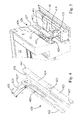
- Figs 6 to 8 a slightly different embodiment of the window is shown.
- an aperture 711 intended for receiving the bolt of the barrel bolt 420 is shown at the bottom of the frame side member 7. This aperture 711 is intended for receiving the barrel bolt in the cleaning position, i.e. when the sash has been turned past its normal opening angle.
- Another aperture 712 is positioned near the top of the frame side member 7. If desirable, this aperture 712 makes it possible to provide a further ventilating position at a relatively small angle, but still allows for more air entrance than by the ventilation flap 400 in itself.
Landscapes
- Engineering & Computer Science (AREA)
- Mechanical Engineering (AREA)
- Architecture (AREA)
- Civil Engineering (AREA)
- Structural Engineering (AREA)
- Wing Frames And Configurations (AREA)
- Hinges (AREA)
Abstract
Description
- The present invention relates to a roof window comprising a frame with a top member, a bottom member and two side members defining a frame plane, and a sash having a top member, a bottom member and two side members defining a sash plane, the roof window further comprising, in connection with the sash top member, a top sash module, the roof window furthermore comprising at least one barrel bolt adapted for releasably locking the sash to the frame in a position of the roof window in which the sash is rotated to a position outside its normal opening range, preferably close to 180 degrees, about a pivot hinge axis with respect to the frame, the barrel bolt comprising a housing and a bolt arranged in the housing in such a way as to be longitudinally displaceable in relation to the housing, the barrel bolt furthermore comprising an operating means. The present invention furthermore relates to such a barrel bolt.
- In known roof windows of this kind the operating means has been made as small as possible both for aesthetic reasons and in order to minimize the amount of material used when producing the barrel bolts.
- In types of windows having elements such as for instance a top sash module provided at the top sash member for ventilation purposes and arranged essentially outside the sash plane of the window, however, the known types of such barrel bolts have turned out to be very difficult to operate, as access to the barrel bolt is impeded.
- It is therefore an object of the present invention to provide in a first aspect of the invention a roof window, and in a second aspect of the invention a barrel bolt, which is more easily operated in all types of windows.
- In a first aspect of the invention, this and other objects are achieved with a roof window of the above kind, where the operating means has an angle with respect to the bolt such that it extends substantially in the direction of a depth axis of the window, and a length such that it terminates approximately level with the surface of the top sash module facing away from the housing of the barrel bolt.
- Thereby a roof window is provided with which the barrel bolt is easy and straightforward to reach and thereby to operate when the user desires to fix the window in a position allowing cleaning of the outside surface of the pane from the inside of a building.
- In a second aspect of the invention, this and other objects are achieved with a barrel bolt for releasably locking a sash of a roof window to a frame of the roof window in a position of the roof window in which the sash is rotated approximately to 180 degrees around a pivot hinge axis with respect to the frame, the barrel bolt comprising a housing and a bolt arranged in the housing in such a way as to be longitudinally displaceable in a telescopic manner within the housing, and an operating means, wherein the operating means of the barrel bolt extends at an angle, preferably at a right angle, with respect to the longitudinal direction of the bolt, and has a length of between 1 and 3 cm. The chosen angle and range of the length makes it possible to attain the easy operation aimed at while still providing for an aesthetically acceptable appearance.
- Preferred embodiments and further advantages will be apparent from the following detailed description and the appended dependent claims.
- The invention will be described in more detail below by means of a non-limiting example of an embodiment and with reference to the schematic drawing, in which
-
Fig. 1 shows a perspective view of a window according to the invention in the assembled state seen from below or inside, -
Fig. 2 shows a perspective view of a window according to the invention in the assembled state seen from above or outside, -
Fig. 3 shows an exploded view of the top of a window according to the invention featuring a top sash module according to the invention, -
Fig. 4 shows an exploded view of the barrel bolt according toFig. 3 , -
Fig. 5 shows a close up view of the barrel bolt according toFig. 3 with the top sash module according toFig. 3 in the mounted position; -
Figs 6 and7 show views corresponding toFigs 1 and 2 showing a slightly different embodiment of the window according to the invention; and -
Fig. 8 shows a partial perspective view of the window shown inFigs 6 and7 . -
Fig. 1 and Fig. 2 show one embodiment of awindow 1 according to the invention comprising apane 4 defining plane 16, aframe 2 having atop member 5, abottom member 6 and twoside members sash 3 having atop member 9, abottom member 10 and twoside members sash 3 is connected to theframe 2 by a pivot hinge (not shown) provided betweenside members frame 2 andsash 3, respectively, to be openable by tilting thesash 3 of thewindow 1 about thepivot hinge axis 21 defined by the pivot hinge. The pivot hinge comprises two parts, namely a sash part and a frame part. - The hinges used are preferably of the type described in the applicant's earlier patent applications
WO9928581 GB1028251 - As used in this description, a closed position of the
window 1 means a position in which the frame plane and the sash plane coincide, that is form an angle of 0 degrees with each other. Similarly an open position of thewindow 1 as used herein generally means a position in which thesash 3 is tilted about thepivot hinge axis 21 such that the frame plane and the sash plane no longer coincide. - As seen in
Fig. 1 alongitudinal axis 13 of thewindow 1 is defined as extending perpendicular to and between the frametop member 5 and theframe bottom member 6, atransversal axis 14 of the window is defined as extending perpendicular to and between the respectiveframe side members longitudinal axis 13 and adepth axis 15 of thewindow 1 is defined as extending perpendicular to both thelongitudinal axis 13 and thetransversal axis 14. Thepivot hinge axis 21 and thetransversal axis 14 are parallel, and are shown as coinciding in the figures. - The
window 1 furthermore comprises alock 17 of a type known per se for locking theframe 2 and sash 3 together as well as a generally circumferentially extending sealing 18 provided on thesash 3 for sealing the gap between thesash 3 and theframe 2 in the closed position of thewindow 1. The sealing 18 comprises at least one, preferably at least two sealing strips. - Notwithstanding the centre-
hung window 1 shown inFig. 1 the window according to the invention may in other embodiments be top-hung, with or without an intermediate frame structure, have the hinge axis somewhere between the top and the centre, be side-hung or for that matter even be bottom-hung. - The
sash 3 andframe 2 of the window according to the invention may be made of wooden members or members made of cast or extruded polyurethane (PUR). - Referring now to
Fig. 3 thewindow 1 comprises in connection with thetop member 9 of the sash 3 atop sash module 411 and aventilation flap 400. Thetop sash module 411 has a substantially rectangular cross section with afirst side 412, asecond side 415 opposite to and extending parallel with saidfirst side 411, athird side 413 and afourth side 414 opposite to and extending parallel with saidthird side 413. The third andfourth sides second sides - The
first side 412 of thetop sash module 411 is adapted to be attached to or abutting a surface of the topsash member 9 opposite thepane 4 of thewindow 1. - The
side sash members window 1 each comprise anextension 417, respectively 416, extending in thelongitudinal direction 13 of thewindow 1 beyond the topsash member 9. The third andfourth sides extensions 416, respectively 417, of theside sash members 12, respectively 11. In this way thetop sash module 411 is placed essentially outside the area delimited by thesash structure 3, i.e. essentially outside the sash plane. - The connection between the
third side 413 and theextension 416, respectively thefourth side 414 and theextension 417, may be achieved in any suitable way, such as by a friction-locking or snap-locking mechanism or even by means of an adhesive or an attachment means such as a screw or a nail. - In a preferred embodiment shown in
Fig. 3 , the third andfourth side attachment member 435, respectively 438, while theextensions corresponding receiving member 437, respectively 439. In the embodiment shown, theattachment members slot 436, respectively 440, while the receivingmembers extensions slots attachment members attachment members members top sash module 411. - The
top sash module 411 is furthermore provided with one ormore ventilation openings 418. For ventilation purposes air is allowed to pass through theventilation openings 418 when theventilation flap 400 is in its open position, while theventilation openings 418 are closed when theventilation flap 400 is in its closed position abutting thetop sash module 411. The amount of air passing theventilation openings 418 may be regulated by means of the intermediate positions of theventilation flap 400. In the closed position of theventilation flap 400, thesash module 411 forms a sealing stop for theventilation flap 400. - The
top sash module 411 may furthermore be provided with at least one, preferably two,protrusions 434, which are arranged in connection with a ventilation opening 418. The protrusion(s) 434 is intended for acting as a guide means for an element 406' connecting thepivot connection 406 and thelock 17. - This arrangement has the advantage compared with the known solutions, that the ventilation arrangement provided by the
top sash module 411 and theventilation flap 400 in combination is positioned essentially outside the plane defined by thesash members top sash module 411 and theventilation flap 400 are positioned in such a way as to enable the area available for thepane 4 to be increased, which in turn allows for more light to be transmitted through the window into a building in which it is installed. Particularly, measurements have shown that this arrangement may increase the pane area by 8 to 9 %, particularly about 8 %. Another advantage provided with this arrangement lies in that thetop casing 500 may be made smaller, which in turn saves material and thus provides for awindow 1 which is cheaper to manufacture. - Furthermore, the
top sash module 411 may be adapted to function as a holder for receiving a gasket or sealing strip for sealing the gap between thetop sash module 411 and thetop frame member 5 in the closed position of thewindow 1. To this end thesecond side 415 of the top sash module may be provided with a recess orgroove 419 extending substantially in the total longitudinal extension of thetop sash module 411. - Preferably, the
recess 419 is arranged such as to be flush with a corresponding recess or groove in the respectiveadjacent extensions side sash members top sash module 411, such as to enable providing thewindow 1 with a preferably circumferentially extending sealing 18 for sealing the gap between thesash 3 and theframe 2 in the closed position of thewindow 1. - Referring now to
Figs 4 and 5 , the window furthermore comprises at least onebarrel bolt 420 comprising ahousing 421 with a first, preferably open,end 427 and a second, preferably closed,end 428, and abolt 422 arranged in thehousing 421 in such a way as to be longitudinally displaceable in relation to thehousing 421 from a first position in which thebolt 422 is placed completely within the housing 421 (cf.Fig. 5 ) to a second position in which thebolt 422 is placed at least partially outside thehousing 422. Thebarrel bolt 420 is mounted in arecess 426 in the topsash member 9 having substantially the same length as thebarrel bolt 420 in such a way that theopen end 427 of thehousing 421 is arranged flush with a transversal end surface of the topsash member 9, while the closedend 428 of thehousing 421 is placed adjacent to or in contact with an end of therecess 426 opposite the transversal end surface of the topsash member 9. Thebarrel bolt 420 is preferably secured to the topsash member 9 by means of a fastening means such as a screw or the like, which is passed through ahole 425 in thehousing 421 as well as anoblong hole 442 in thebolt 422, theoblong hole 442 ensuring that thebolt 422 may be displaced longitudinally within the housing. - Preferably, the
window 1 comprises twobarrel bolts 420, one at each end of the topsash member 9. - The
barrel bolt 420 comprises an operating means 423, such as a grip, extending through anoblong hole 424 provided in thehousing 421 of thebarrel bolt 420, the extension of the oblong hole 424 (and/or the oblong hole 442) defining the extension of the longitudinal displacement of thebolt 422 in thehousing 421. - The operating means 423 extends at an angle, preferably at a right angle, with respect to the longitudinal direction of the
bolt 422, and has a length I of preferably between 1 and 3 cm. - The operating means 423 extends at an angle, preferably at a substantially right angle, with respect to the
bolt 422. Preferably, in the mounted position of thebarrel bolt 420, the operating means 423 has an angle with respect to thewindow 1 such that it extends substantially in the direction of thedepth axis 15 of thewindow 1, and a length such that it terminates approximately level with the surface of thetop sash module 411 facing away from thehousing 421 of thebarrel bolt 420. In other words the length of the operating means 423 is such that it in the mounted position of thebarrel bolt 420 extends in the direction of thedepth axis 15 of thewindow 1 in a distance corresponding to but not exceeding the sum of the distance between thebarrel bolt 420 and thetop sash module 411 and the thickness of thetop sash module 411. - This provides for a
barrel bolt 420 which is easy to grip and consequently to operate, particularly when applied in combination with the top sash module described above. - The operating means 423 is preferably shaped in such a way as to provide
surfaces 423', 423" adapted for being securely gripped between two human fingers. - The
barrel bolt 420 is intended for releasably locking thesash 3 to theframe 2 in a position of thewindow 1 in which thesash 3 is rotated past its normal opening range. Such an angle may be close to 180 degrees, but may also be smaller, depending i.a. on the dimensions of the frame and the sash. Thesash 3 is rotated around thepivot hinge axis 21 with respect to theframe 2 and the engagement between parts of the hinge is released in a manner known to the person skilled in the art in such pivot hinges, such as to enable a user to clean the outside surface of thewindow 1, particularly of thepane 4, from within a building in which thewindow 1 is mounted. To this end at least one of theside frame members Figs 1 to 5 ) adapted for receiving thebolt 422 of thebarrel bolt 420 at least partially, which recess may optionally comprise an insert preferably made of plastic. The insert may comprise retaining means such as barbs for retaining it in the recess. Hence, thebarrel bolt 420 is particularly useful for centre hung and semi-centre hung windows, but may nevertheless be used for any type of window. - Referring now to
Figs 6 to 8 , a slightly different embodiment of the window is shown. - Here, an
aperture 711 intended for receiving the bolt of thebarrel bolt 420 is shown at the bottom of theframe side member 7. Thisaperture 711 is intended for receiving the barrel bolt in the cleaning position, i.e. when the sash has been turned past its normal opening angle. - Another
aperture 712 is positioned near the top of theframe side member 7. If desirable, thisaperture 712 makes it possible to provide a further ventilating position at a relatively small angle, but still allows for more air entrance than by theventilation flap 400 in itself. - It should be noted that the above description of preferred embodiments serves only as an example, and that a person skilled in the art will know that numerous variations are possible without deviating from the scope of the claims.
Claims (10)
- A roof window (1) comprising a frame (2) with a top member (5), a bottom member (6) and two side members (7, 8) defining a frame plane, and a sash (3) having a top member (9), a bottom member (10) and two side members (11, 12) defining a sash plane,
the roof window (1) further comprising, in connection with said sash top member (9), a top sash module (411),
the roof window (1) furthermore comprising at least one barrel bolt (420) adapted for releasably locking the sash (3) to the frame (2) in a position of the roof window (1) in which the sash (3) is rotated to a position outside its normal opening range, preferably close to 180 degrees, about a pivot hinge axis (21) with respect to the frame (2), the barrel bolt (420) comprising a housing (421) and a bolt (422) arranged in the housing (421) in such a way as to be longitudinally displaceable in relation to the housing (421), the barrel bolt (420) furthermore comprising an operating means (423),
characterized in that
the operating means (423) has an angle with respect to the bolt (422) such that it extends substantially in the direction of a depth axis (15) of the window (1), and a length (I) such that it terminates approximately level with the surface of the top sash module (411) facing away from the housing (421) of the barrel bolt (420). - A roof window according to claim 1, wherein the length (I) of the operating means (423) is such that it in the mounted position of the barrel bolt (420) extends in the direction of the depth axis (15) of the window (1) in a distance corresponding to but not exceeding the sum of the distance between the barrel bolt (420) and the top sash module (411) and the thickness of the top sash module (411).
- A roof window according to claim 1 or 2, wherein said top sash module (411) comprises at least one opening, preferably a ventilation opening (418), said operating means (423) of said barrel bolt (420) extending through said at least one opening.
- A roof window according to any one of the preceding claims, wherein said bolt (422) is arranged in the housing (421) in such a way as to be longitudinally displaceable in a telescopic manner within the housing (421) from a first position in which the bolt (422) is placed completely within the housing (421) to a second position in which the bolt (422) is placed at least partially outside the housing (421).
- A roof window according to claim 4, wherein said housing (421) of the barrel bolt (420) comprises a first open end (427) and a second closed end (428) and that said barrel bolt (420) is mounted in a recess (426) in the top sash member (9) in such a way that the open end (427) of the housing (421) is arranged flush with a transversal end surface of the top sash member (9), while the closed end (428) of the housing (421) is placed adjacent to or in contact with an end of the recess (426) opposite the transversal end surface of the top sash member (9).
- A roof window according to any one of the preceding claims, wherein said barrel bolt (420) is secured to the top sash member (9) by means of a fastening means, such as a screw or the like, said fastening means preferably being passed through a hole (425) in the housing (421) as well as an oblong hole (442) in the bolt (422).
- A roof window according to any one of the preceding claims, wherein the operating means (423) extends through an oblong hole (424) provided in the housing (421) of the barrel bolt (420), the extension of the oblong hole (424) in the housing (421) and/or the oblong hole (442) in the bolt (422) defining the extension of the longitudinal displacement of the bolt (422) in the housing (421).
- A roof window according to any one of the preceding claims, wherein the length (I) of the operating means (423) is between 1 and 3 cm, preferably between 2 and 3 cm and/or in that the operating means (423) is shaped with surfaces (423', 423") adapted for being securely gripped between two human fingers.
- A barrel bolt (420) for releasably locking a sash (3) of a roof window (1) to a frame (2) of the roof window (1) in a position of the roof window (1) in which the sash (3) is rotated approximately to 180 degrees around a pivot hinge axis (21) with respect to the frame (2), the barrel bolt (420) comprising
a housing (421) and a bolt (422) arranged in the housing (421) in such a way as to be longitudinally displaceable in a telescopic manner within the housing (421), and
an operating means (423),
characterized in that
the operating means (423) extends at an angle, preferably at a right angle, with respect to the longitudinal direction of the bolt (422), and has a length (I) of between 1 and 3 cm. - A barrel bolt according to claim 9, wherein the length (I) of the operating means (423) is between 2 and 3 cm.
Priority Applications (1)
| Application Number | Priority Date | Filing Date | Title |
|---|---|---|---|
| PL12187167T PL2578764T3 (en) | 2011-10-04 | 2012-10-04 | A roof window with a barrel bolt |
Applications Claiming Priority (1)
| Application Number | Priority Date | Filing Date | Title |
|---|---|---|---|
| DKPA201170551 | 2011-10-04 |
Publications (2)
| Publication Number | Publication Date |
|---|---|
| EP2578764A1 true EP2578764A1 (en) | 2013-04-10 |
| EP2578764B1 EP2578764B1 (en) | 2014-06-18 |
Family
ID=47080232
Family Applications (1)
| Application Number | Title | Priority Date | Filing Date |
|---|---|---|---|
| EP12187167.7A Active EP2578764B1 (en) | 2011-10-04 | 2012-10-04 | A roof window with a barrel bolt |
Country Status (4)
| Country | Link |
|---|---|
| EP (1) | EP2578764B1 (en) |
| DK (1) | DK2578764T3 (en) |
| ES (1) | ES2498949T3 (en) |
| PL (1) | PL2578764T3 (en) |
Cited By (4)
| Publication number | Priority date | Publication date | Assignee | Title |
|---|---|---|---|---|
| CN104895470A (en) * | 2014-03-03 | 2015-09-09 | Vkr控股公司 | Ventilation and operating assembly having a locking device |
| EP2751355B1 (en) | 2011-10-04 | 2015-11-25 | VKR Holding A/S | A roof window with a top sash module |
| EP3348771A1 (en) * | 2017-01-13 | 2018-07-18 | Keylite Roof Windows Limited | Window ventilation system and window |
| CN114045995A (en) * | 2021-11-19 | 2022-02-15 | 河北华腾亿州电气设备有限公司 | Multi-stage linkage type turnover skylight device |
Families Citing this family (1)
| Publication number | Priority date | Publication date | Assignee | Title |
|---|---|---|---|---|
| CN106592881A (en) * | 2017-01-17 | 2017-04-26 | 泉州施米德智能科技有限公司 | House skylight capable of purifying air |
Citations (3)
| Publication number | Priority date | Publication date | Assignee | Title |
|---|---|---|---|---|
| GB1028251A (en) | 1963-01-31 | 1966-05-04 | Villum Benedikt Kann Rasmussen | Improvements in and relating to a hinge mounting for pivotal and tiltable windows |
| WO1999028581A1 (en) | 1997-11-11 | 1999-06-10 | Velux Industri A/S | A hinge fitting for a pivotal window |
| EP2157262A1 (en) * | 2008-08-19 | 2010-02-24 | T.J.de Rooij Wood Desing | Burglar security for roof skylight window |
-
2012
- 2012-10-04 PL PL12187167T patent/PL2578764T3/en unknown
- 2012-10-04 EP EP12187167.7A patent/EP2578764B1/en active Active
- 2012-10-04 DK DK12187167.7T patent/DK2578764T3/en active
- 2012-10-04 ES ES12187167.7T patent/ES2498949T3/en active Active
Patent Citations (3)
| Publication number | Priority date | Publication date | Assignee | Title |
|---|---|---|---|---|
| GB1028251A (en) | 1963-01-31 | 1966-05-04 | Villum Benedikt Kann Rasmussen | Improvements in and relating to a hinge mounting for pivotal and tiltable windows |
| WO1999028581A1 (en) | 1997-11-11 | 1999-06-10 | Velux Industri A/S | A hinge fitting for a pivotal window |
| EP2157262A1 (en) * | 2008-08-19 | 2010-02-24 | T.J.de Rooij Wood Desing | Burglar security for roof skylight window |
Cited By (5)
| Publication number | Priority date | Publication date | Assignee | Title |
|---|---|---|---|---|
| EP2751355B1 (en) | 2011-10-04 | 2015-11-25 | VKR Holding A/S | A roof window with a top sash module |
| EP2751355B2 (en) † | 2011-10-04 | 2018-11-21 | VKR Holding A/S | A roof window with a top sash module |
| CN104895470A (en) * | 2014-03-03 | 2015-09-09 | Vkr控股公司 | Ventilation and operating assembly having a locking device |
| EP3348771A1 (en) * | 2017-01-13 | 2018-07-18 | Keylite Roof Windows Limited | Window ventilation system and window |
| CN114045995A (en) * | 2021-11-19 | 2022-02-15 | 河北华腾亿州电气设备有限公司 | Multi-stage linkage type turnover skylight device |
Also Published As
| Publication number | Publication date |
|---|---|
| DK2578764T3 (en) | 2014-08-18 |
| EP2578764B1 (en) | 2014-06-18 |
| ES2498949T3 (en) | 2014-09-26 |
| PL2578764T3 (en) | 2014-11-28 |
Similar Documents
| Publication | Publication Date | Title |
|---|---|---|
| EP2751355B2 (en) | A roof window with a top sash module | |
| EP2578764B1 (en) | A roof window with a barrel bolt | |
| EP2748390B1 (en) | A roof window with an insulating element | |
| CN204252419U (en) | Roof skylights with improved impact bead coverings | |
| US7963071B2 (en) | Louvre window system | |
| US9469995B2 (en) | Roof window with a cover and a covering fastening device | |
| US6202373B1 (en) | Top-hung window | |
| US20240418030A1 (en) | Configurable astragal and snap feature for fenestration systems | |
| US7392628B2 (en) | Functional shutter | |
| KR20190001418U (en) | Windshield for sliding windows and doors | |
| US5682715A (en) | Two piece center mull for multiple door assembly | |
| JP2008202269A (en) | Synthetic resin sash | |
| JP3896545B2 (en) | Architectural profile | |
| AU784774B2 (en) | Sliding screen assembly | |
| JPS5938632Y2 (en) | Shoji stile | |
| AU731477B2 (en) | Door handle with glazing strip | |
| AU768469B2 (en) | A louvre blade | |
| WO2001006083A1 (en) | A louvre blade | |
| AU2002342406B2 (en) | A louvre system | |
| AU2013204696A1 (en) | A Louvre System | |
| GB2332468A (en) | Weatherbar with drainage holes | |
| AU1882902A (en) | Sliding screen closure assembly |
Legal Events
| Date | Code | Title | Description |
|---|---|---|---|
| PUAI | Public reference made under article 153(3) epc to a published international application that has entered the european phase |
Free format text: ORIGINAL CODE: 0009012 |
|
| AK | Designated contracting states |
Kind code of ref document: A1 Designated state(s): AL AT BE BG CH CY CZ DE DK EE ES FI FR GB GR HR HU IE IS IT LI LT LU LV MC MK MT NL NO PL PT RO RS SE SI SK SM TR |
|
| AX | Request for extension of the european patent |
Extension state: BA ME |
|
| 17P | Request for examination filed |
Effective date: 20131010 |
|
| RBV | Designated contracting states (corrected) |
Designated state(s): AL AT BE BG CH CY CZ DE DK EE ES FI FR GB GR HR HU IE IS IT LI LT LU LV MC MK MT NL NO PL PT RO RS SE SI SK SM TR |
|
| GRAP | Despatch of communication of intention to grant a patent |
Free format text: ORIGINAL CODE: EPIDOSNIGR1 |
|
| RIC1 | Information provided on ipc code assigned before grant |
Ipc: E04D 13/03 20060101AFI20140114BHEP Ipc: E04D 13/035 20060101ALI20140114BHEP Ipc: E05C 1/10 20060101ALI20140114BHEP |
|
| INTG | Intention to grant announced |
Effective date: 20140131 |
|
| GRAS | Grant fee paid |
Free format text: ORIGINAL CODE: EPIDOSNIGR3 |
|
| GRAA | (expected) grant |
Free format text: ORIGINAL CODE: 0009210 |
|
| AK | Designated contracting states |
Kind code of ref document: B1 Designated state(s): AL AT BE BG CH CY CZ DE DK EE ES FI FR GB GR HR HU IE IS IT LI LT LU LV MC MK MT NL NO PL PT RO RS SE SI SK SM TR |
|
| REG | Reference to a national code |
Ref country code: GB Ref legal event code: FG4D |
|
| REG | Reference to a national code |
Ref country code: CH Ref legal event code: EP |
|
| REG | Reference to a national code |
Ref country code: AT Ref legal event code: REF Ref document number: 673461 Country of ref document: AT Kind code of ref document: T Effective date: 20140715 |
|
| REG | Reference to a national code |
Ref country code: IE Ref legal event code: FG4D |
|
| REG | Reference to a national code |
Ref country code: DE Ref legal event code: R096 Ref document number: 602012002137 Country of ref document: DE Effective date: 20140731 |
|
| REG | Reference to a national code |
Ref country code: DK Ref legal event code: T3 Effective date: 20140814 |
|
| REG | Reference to a national code |
Ref country code: NL Ref legal event code: T3 |
|
| REG | Reference to a national code |
Ref country code: ES Ref legal event code: FG2A Ref document number: 2498949 Country of ref document: ES Kind code of ref document: T3 Effective date: 20140926 |
|
| PG25 | Lapsed in a contracting state [announced via postgrant information from national office to epo] |
Ref country code: GR Free format text: LAPSE BECAUSE OF FAILURE TO SUBMIT A TRANSLATION OF THE DESCRIPTION OR TO PAY THE FEE WITHIN THE PRESCRIBED TIME-LIMIT Effective date: 20140919 Ref country code: LT Free format text: LAPSE BECAUSE OF FAILURE TO SUBMIT A TRANSLATION OF THE DESCRIPTION OR TO PAY THE FEE WITHIN THE PRESCRIBED TIME-LIMIT Effective date: 20140618 Ref country code: FI Free format text: LAPSE BECAUSE OF FAILURE TO SUBMIT A TRANSLATION OF THE DESCRIPTION OR TO PAY THE FEE WITHIN THE PRESCRIBED TIME-LIMIT Effective date: 20140618 Ref country code: NO Free format text: LAPSE BECAUSE OF FAILURE TO SUBMIT A TRANSLATION OF THE DESCRIPTION OR TO PAY THE FEE WITHIN THE PRESCRIBED TIME-LIMIT Effective date: 20140918 Ref country code: CY Free format text: LAPSE BECAUSE OF FAILURE TO SUBMIT A TRANSLATION OF THE DESCRIPTION OR TO PAY THE FEE WITHIN THE PRESCRIBED TIME-LIMIT Effective date: 20140618 |
|
| REG | Reference to a national code |
Ref country code: LT Ref legal event code: MG4D |
|
| PG25 | Lapsed in a contracting state [announced via postgrant information from national office to epo] |
Ref country code: SE Free format text: LAPSE BECAUSE OF FAILURE TO SUBMIT A TRANSLATION OF THE DESCRIPTION OR TO PAY THE FEE WITHIN THE PRESCRIBED TIME-LIMIT Effective date: 20140618 Ref country code: LV Free format text: LAPSE BECAUSE OF FAILURE TO SUBMIT A TRANSLATION OF THE DESCRIPTION OR TO PAY THE FEE WITHIN THE PRESCRIBED TIME-LIMIT Effective date: 20140618 Ref country code: RS Free format text: LAPSE BECAUSE OF FAILURE TO SUBMIT A TRANSLATION OF THE DESCRIPTION OR TO PAY THE FEE WITHIN THE PRESCRIBED TIME-LIMIT Effective date: 20140618 Ref country code: HR Free format text: LAPSE BECAUSE OF FAILURE TO SUBMIT A TRANSLATION OF THE DESCRIPTION OR TO PAY THE FEE WITHIN THE PRESCRIBED TIME-LIMIT Effective date: 20140618 |
|
| REG | Reference to a national code |
Ref country code: PL Ref legal event code: T3 |
|
| REG | Reference to a national code |
Ref country code: SK Ref legal event code: T3 Ref document number: E 17274 Country of ref document: SK |
|
| PG25 | Lapsed in a contracting state [announced via postgrant information from national office to epo] |
Ref country code: PT Free format text: LAPSE BECAUSE OF FAILURE TO SUBMIT A TRANSLATION OF THE DESCRIPTION OR TO PAY THE FEE WITHIN THE PRESCRIBED TIME-LIMIT Effective date: 20141020 Ref country code: RO Free format text: LAPSE BECAUSE OF FAILURE TO SUBMIT A TRANSLATION OF THE DESCRIPTION OR TO PAY THE FEE WITHIN THE PRESCRIBED TIME-LIMIT Effective date: 20140618 Ref country code: EE Free format text: LAPSE BECAUSE OF FAILURE TO SUBMIT A TRANSLATION OF THE DESCRIPTION OR TO PAY THE FEE WITHIN THE PRESCRIBED TIME-LIMIT Effective date: 20140618 |
|
| PG25 | Lapsed in a contracting state [announced via postgrant information from national office to epo] |
Ref country code: IS Free format text: LAPSE BECAUSE OF FAILURE TO SUBMIT A TRANSLATION OF THE DESCRIPTION OR TO PAY THE FEE WITHIN THE PRESCRIBED TIME-LIMIT Effective date: 20141018 |
|
| REG | Reference to a national code |
Ref country code: HU Ref legal event code: AG4A Ref document number: E021819 Country of ref document: HU |
|
| REG | Reference to a national code |
Ref country code: DE Ref legal event code: R097 Ref document number: 602012002137 Country of ref document: DE |
|
| PLBE | No opposition filed within time limit |
Free format text: ORIGINAL CODE: 0009261 |
|
| STAA | Information on the status of an ep patent application or granted ep patent |
Free format text: STATUS: NO OPPOSITION FILED WITHIN TIME LIMIT |
|
| 26N | No opposition filed |
Effective date: 20150319 |
|
| PG25 | Lapsed in a contracting state [announced via postgrant information from national office to epo] |
Ref country code: LU Free format text: LAPSE BECAUSE OF FAILURE TO SUBMIT A TRANSLATION OF THE DESCRIPTION OR TO PAY THE FEE WITHIN THE PRESCRIBED TIME-LIMIT Effective date: 20141004 Ref country code: MC Free format text: LAPSE BECAUSE OF FAILURE TO SUBMIT A TRANSLATION OF THE DESCRIPTION OR TO PAY THE FEE WITHIN THE PRESCRIBED TIME-LIMIT Effective date: 20140618 |
|
| REG | Reference to a national code |
Ref country code: IE Ref legal event code: MM4A |
|
| PG25 | Lapsed in a contracting state [announced via postgrant information from national office to epo] |
Ref country code: SI Free format text: LAPSE BECAUSE OF FAILURE TO SUBMIT A TRANSLATION OF THE DESCRIPTION OR TO PAY THE FEE WITHIN THE PRESCRIBED TIME-LIMIT Effective date: 20140618 |
|
| PG25 | Lapsed in a contracting state [announced via postgrant information from national office to epo] |
Ref country code: IE Free format text: LAPSE BECAUSE OF NON-PAYMENT OF DUE FEES Effective date: 20141004 |
|
| REG | Reference to a national code |
Ref country code: HU Ref legal event code: HC9C |
|
| PG25 | Lapsed in a contracting state [announced via postgrant information from national office to epo] |
Ref country code: BG Free format text: LAPSE BECAUSE OF FAILURE TO SUBMIT A TRANSLATION OF THE DESCRIPTION OR TO PAY THE FEE WITHIN THE PRESCRIBED TIME-LIMIT Effective date: 20140618 |
|
| PG25 | Lapsed in a contracting state [announced via postgrant information from national office to epo] |
Ref country code: MT Free format text: LAPSE BECAUSE OF FAILURE TO SUBMIT A TRANSLATION OF THE DESCRIPTION OR TO PAY THE FEE WITHIN THE PRESCRIBED TIME-LIMIT Effective date: 20140618 Ref country code: TR Free format text: LAPSE BECAUSE OF FAILURE TO SUBMIT A TRANSLATION OF THE DESCRIPTION OR TO PAY THE FEE WITHIN THE PRESCRIBED TIME-LIMIT Effective date: 20140618 |
|
| REG | Reference to a national code |
Ref country code: FR Ref legal event code: PLFP Year of fee payment: 5 |
|
| PG25 | Lapsed in a contracting state [announced via postgrant information from national office to epo] |
Ref country code: SM Free format text: LAPSE BECAUSE OF FAILURE TO SUBMIT A TRANSLATION OF THE DESCRIPTION OR TO PAY THE FEE WITHIN THE PRESCRIBED TIME-LIMIT Effective date: 20140618 |
|
| REG | Reference to a national code |
Ref country code: FR Ref legal event code: PLFP Year of fee payment: 6 |
|
| PG25 | Lapsed in a contracting state [announced via postgrant information from national office to epo] |
Ref country code: MK Free format text: LAPSE BECAUSE OF FAILURE TO SUBMIT A TRANSLATION OF THE DESCRIPTION OR TO PAY THE FEE WITHIN THE PRESCRIBED TIME-LIMIT Effective date: 20140618 |
|
| REG | Reference to a national code |
Ref country code: FR Ref legal event code: PLFP Year of fee payment: 7 |
|
| PG25 | Lapsed in a contracting state [announced via postgrant information from national office to epo] |
Ref country code: AL Free format text: LAPSE BECAUSE OF FAILURE TO SUBMIT A TRANSLATION OF THE DESCRIPTION OR TO PAY THE FEE WITHIN THE PRESCRIBED TIME-LIMIT Effective date: 20140618 |
|
| PGFP | Annual fee paid to national office [announced via postgrant information from national office to epo] |
Ref country code: DK Payment date: 20241011 Year of fee payment: 13 |
|
| PGFP | Annual fee paid to national office [announced via postgrant information from national office to epo] |
Ref country code: PL Payment date: 20250912 Year of fee payment: 14 Ref country code: NL Payment date: 20250912 Year of fee payment: 14 Ref country code: IT Payment date: 20250922 Year of fee payment: 14 |
|
| PGFP | Annual fee paid to national office [announced via postgrant information from national office to epo] |
Ref country code: BE Payment date: 20250917 Year of fee payment: 14 Ref country code: GB Payment date: 20250904 Year of fee payment: 14 |
|
| PGFP | Annual fee paid to national office [announced via postgrant information from national office to epo] |
Ref country code: FR Payment date: 20250922 Year of fee payment: 14 |
|
| PGFP | Annual fee paid to national office [announced via postgrant information from national office to epo] |
Ref country code: CZ Payment date: 20250929 Year of fee payment: 14 |
|
| PGFP | Annual fee paid to national office [announced via postgrant information from national office to epo] |
Ref country code: SK Payment date: 20250912 Year of fee payment: 14 |
|
| REG | Reference to a national code |
Ref country code: CH Ref legal event code: U11 Free format text: ST27 STATUS EVENT CODE: U-0-0-U10-U11 (AS PROVIDED BY THE NATIONAL OFFICE) Effective date: 20251101 |
|
| PGFP | Annual fee paid to national office [announced via postgrant information from national office to epo] |
Ref country code: HU Payment date: 20250929 Year of fee payment: 14 |
|
| PGFP | Annual fee paid to national office [announced via postgrant information from national office to epo] |
Ref country code: DE Payment date: 20250902 Year of fee payment: 14 |
|
| PGFP | Annual fee paid to national office [announced via postgrant information from national office to epo] |
Ref country code: AT Payment date: 20250925 Year of fee payment: 14 |
|
| PGFP | Annual fee paid to national office [announced via postgrant information from national office to epo] |
Ref country code: CH Payment date: 20251101 Year of fee payment: 14 |
|
| PGFP | Annual fee paid to national office [announced via postgrant information from national office to epo] |
Ref country code: ES Payment date: 20251104 Year of fee payment: 14 |