EP2578384B1 - Fibre guiding device and use thereof - Google Patents
Fibre guiding device and use thereof Download PDFInfo
- Publication number
- EP2578384B1 EP2578384B1 EP12193003.6A EP12193003A EP2578384B1 EP 2578384 B1 EP2578384 B1 EP 2578384B1 EP 12193003 A EP12193003 A EP 12193003A EP 2578384 B1 EP2578384 B1 EP 2578384B1
- Authority
- EP
- European Patent Office
- Prior art keywords
- fibre
- fiber
- fibers
- workpiece carrier
- preform
- Prior art date
- Legal status (The legal status is an assumption and is not a legal conclusion. Google has not performed a legal analysis and makes no representation as to the accuracy of the status listed.)
- Not-in-force
Links
- 239000000835 fiber Substances 0.000 title claims description 256
- 238000005520 cutting process Methods 0.000 claims description 38
- 238000012546 transfer Methods 0.000 claims description 23
- 239000002131 composite material Substances 0.000 claims description 17
- 238000004519 manufacturing process Methods 0.000 claims description 15
- 238000005452 bending Methods 0.000 claims description 4
- 239000011347 resin Substances 0.000 description 45
- 229920005989 resin Polymers 0.000 description 45
- 239000010408 film Substances 0.000 description 42
- 238000000034 method Methods 0.000 description 31
- 239000000853 adhesive Substances 0.000 description 28
- 230000001070 adhesive effect Effects 0.000 description 28
- 230000007246 mechanism Effects 0.000 description 18
- 239000011265 semifinished product Substances 0.000 description 15
- 238000000151 deposition Methods 0.000 description 12
- 230000008569 process Effects 0.000 description 10
- 230000008901 benefit Effects 0.000 description 8
- 238000004806 packaging method and process Methods 0.000 description 7
- 238000005470 impregnation Methods 0.000 description 6
- 239000011159 matrix material Substances 0.000 description 6
- 229920000049 Carbon (fiber) Polymers 0.000 description 5
- 239000011230 binding agent Substances 0.000 description 5
- 239000004917 carbon fiber Substances 0.000 description 5
- 238000002347 injection Methods 0.000 description 5
- 239000007924 injection Substances 0.000 description 5
- 238000003860 storage Methods 0.000 description 5
- 229920001169 thermoplastic Polymers 0.000 description 5
- 239000004416 thermosoftening plastic Substances 0.000 description 5
- 239000004744 fabric Substances 0.000 description 4
- 239000003365 glass fiber Substances 0.000 description 4
- 238000012545 processing Methods 0.000 description 4
- 239000012783 reinforcing fiber Substances 0.000 description 4
- 238000009958 sewing Methods 0.000 description 4
- 229920001187 thermosetting polymer Polymers 0.000 description 4
- 239000011324 bead Substances 0.000 description 3
- 230000005540 biological transmission Effects 0.000 description 3
- 230000000694 effects Effects 0.000 description 3
- 239000011888 foil Substances 0.000 description 3
- 238000007710 freezing Methods 0.000 description 3
- 230000008014 freezing Effects 0.000 description 3
- 238000012432 intermediate storage Methods 0.000 description 3
- 239000000463 material Substances 0.000 description 3
- 238000000465 moulding Methods 0.000 description 3
- 238000002360 preparation method Methods 0.000 description 3
- 230000002787 reinforcement Effects 0.000 description 3
- 238000004026 adhesive bonding Methods 0.000 description 2
- 230000015572 biosynthetic process Effects 0.000 description 2
- 239000000969 carrier Substances 0.000 description 2
- 238000000576 coating method Methods 0.000 description 2
- 230000003750 conditioning effect Effects 0.000 description 2
- 238000010276 construction Methods 0.000 description 2
- 239000002826 coolant Substances 0.000 description 2
- 238000001816 cooling Methods 0.000 description 2
- 230000008021 deposition Effects 0.000 description 2
- 239000000047 product Substances 0.000 description 2
- 238000000926 separation method Methods 0.000 description 2
- 239000007921 spray Substances 0.000 description 2
- 238000005507 spraying Methods 0.000 description 2
- 238000003892 spreading Methods 0.000 description 2
- 230000007480 spreading Effects 0.000 description 2
- 239000007858 starting material Substances 0.000 description 2
- 239000004753 textile Substances 0.000 description 2
- XLYOFNOQVPJJNP-UHFFFAOYSA-N water Substances O XLYOFNOQVPJJNP-UHFFFAOYSA-N 0.000 description 2
- 241001136792 Alle Species 0.000 description 1
- 230000003213 activating effect Effects 0.000 description 1
- 239000004760 aramid Substances 0.000 description 1
- 229920006231 aramid fiber Polymers 0.000 description 1
- 238000009954 braiding Methods 0.000 description 1
- 239000011248 coating agent Substances 0.000 description 1
- 230000000295 complement effect Effects 0.000 description 1
- 238000011161 development Methods 0.000 description 1
- 230000018109 developmental process Effects 0.000 description 1
- 238000000469 dry deposition Methods 0.000 description 1
- 238000000605 extraction Methods 0.000 description 1
- 239000002657 fibrous material Substances 0.000 description 1
- 238000011049 filling Methods 0.000 description 1
- 239000003292 glue Substances 0.000 description 1
- 238000000265 homogenisation Methods 0.000 description 1
- 238000007731 hot pressing Methods 0.000 description 1
- 238000001802 infusion Methods 0.000 description 1
- 238000009940 knitting Methods 0.000 description 1
- 239000004922 lacquer Substances 0.000 description 1
- 239000007788 liquid Substances 0.000 description 1
- VNWKTOKETHGBQD-UHFFFAOYSA-N methane Chemical compound C VNWKTOKETHGBQD-UHFFFAOYSA-N 0.000 description 1
- 238000002156 mixing Methods 0.000 description 1
- 239000000203 mixture Substances 0.000 description 1
- 230000004048 modification Effects 0.000 description 1
- 238000012986 modification Methods 0.000 description 1
- 229920000642 polymer Polymers 0.000 description 1
- 239000002994 raw material Substances 0.000 description 1
- 230000009467 reduction Effects 0.000 description 1
- 239000003507 refrigerant Substances 0.000 description 1
- 230000001105 regulatory effect Effects 0.000 description 1
- 230000003014 reinforcing effect Effects 0.000 description 1
- 238000007665 sagging Methods 0.000 description 1
- 238000007493 shaping process Methods 0.000 description 1
- 238000010008 shearing Methods 0.000 description 1
- 239000000243 solution Substances 0.000 description 1
- 230000006641 stabilisation Effects 0.000 description 1
- 238000011105 stabilization Methods 0.000 description 1
- 230000000087 stabilizing effect Effects 0.000 description 1
- 238000003756 stirring Methods 0.000 description 1
- 239000000126 substance Substances 0.000 description 1
- 239000013589 supplement Substances 0.000 description 1
- 239000012815 thermoplastic material Substances 0.000 description 1
- 239000004634 thermosetting polymer Substances 0.000 description 1
- 239000010409 thin film Substances 0.000 description 1
- 238000009827 uniform distribution Methods 0.000 description 1
- 239000002759 woven fabric Substances 0.000 description 1
Images


Classifications
-
- B—PERFORMING OPERATIONS; TRANSPORTING
- B29—WORKING OF PLASTICS; WORKING OF SUBSTANCES IN A PLASTIC STATE IN GENERAL
- B29C—SHAPING OR JOINING OF PLASTICS; SHAPING OF MATERIAL IN A PLASTIC STATE, NOT OTHERWISE PROVIDED FOR; AFTER-TREATMENT OF THE SHAPED PRODUCTS, e.g. REPAIRING
- B29C67/00—Shaping techniques not covered by groups B29C39/00 - B29C65/00, B29C70/00 or B29C73/00
- B29C67/24—Shaping techniques not covered by groups B29C39/00 - B29C65/00, B29C70/00 or B29C73/00 characterised by the choice of material
-
- B—PERFORMING OPERATIONS; TRANSPORTING
- B29—WORKING OF PLASTICS; WORKING OF SUBSTANCES IN A PLASTIC STATE IN GENERAL
- B29B—PREPARATION OR PRETREATMENT OF THE MATERIAL TO BE SHAPED; MAKING GRANULES OR PREFORMS; RECOVERY OF PLASTICS OR OTHER CONSTITUENTS OF WASTE MATERIAL CONTAINING PLASTICS
- B29B11/00—Making preforms
- B29B11/14—Making preforms characterised by structure or composition
- B29B11/16—Making preforms characterised by structure or composition comprising fillers or reinforcement
-
- B—PERFORMING OPERATIONS; TRANSPORTING
- B29—WORKING OF PLASTICS; WORKING OF SUBSTANCES IN A PLASTIC STATE IN GENERAL
- B29C—SHAPING OR JOINING OF PLASTICS; SHAPING OF MATERIAL IN A PLASTIC STATE, NOT OTHERWISE PROVIDED FOR; AFTER-TREATMENT OF THE SHAPED PRODUCTS, e.g. REPAIRING
- B29C70/00—Shaping composites, i.e. plastics material comprising reinforcements, fillers or preformed parts, e.g. inserts
- B29C70/04—Shaping composites, i.e. plastics material comprising reinforcements, fillers or preformed parts, e.g. inserts comprising reinforcements only, e.g. self-reinforcing plastics
- B29C70/28—Shaping operations therefor
- B29C70/30—Shaping by lay-up, i.e. applying fibres, tape or broadsheet on a mould, former or core; Shaping by spray-up, i.e. spraying of fibres on a mould, former or core
- B29C70/38—Automated lay-up, e.g. using robots, laying filaments according to predetermined patterns
- B29C70/382—Automated fiber placement [AFP]
-
- B—PERFORMING OPERATIONS; TRANSPORTING
- B29—WORKING OF PLASTICS; WORKING OF SUBSTANCES IN A PLASTIC STATE IN GENERAL
- B29C—SHAPING OR JOINING OF PLASTICS; SHAPING OF MATERIAL IN A PLASTIC STATE, NOT OTHERWISE PROVIDED FOR; AFTER-TREATMENT OF THE SHAPED PRODUCTS, e.g. REPAIRING
- B29C70/00—Shaping composites, i.e. plastics material comprising reinforcements, fillers or preformed parts, e.g. inserts
- B29C70/04—Shaping composites, i.e. plastics material comprising reinforcements, fillers or preformed parts, e.g. inserts comprising reinforcements only, e.g. self-reinforcing plastics
- B29C70/28—Shaping operations therefor
- B29C70/54—Component parts, details or accessories; Auxiliary operations, e.g. feeding or storage of prepregs or SMC after impregnation or during ageing
- B29C70/541—Positioning reinforcements in a mould, e.g. using clamping means for the reinforcement
-
- B—PERFORMING OPERATIONS; TRANSPORTING
- B29—WORKING OF PLASTICS; WORKING OF SUBSTANCES IN A PLASTIC STATE IN GENERAL
- B29C—SHAPING OR JOINING OF PLASTICS; SHAPING OF MATERIAL IN A PLASTIC STATE, NOT OTHERWISE PROVIDED FOR; AFTER-TREATMENT OF THE SHAPED PRODUCTS, e.g. REPAIRING
- B29C70/00—Shaping composites, i.e. plastics material comprising reinforcements, fillers or preformed parts, e.g. inserts
- B29C70/04—Shaping composites, i.e. plastics material comprising reinforcements, fillers or preformed parts, e.g. inserts comprising reinforcements only, e.g. self-reinforcing plastics
- B29C70/28—Shaping operations therefor
- B29C70/54—Component parts, details or accessories; Auxiliary operations, e.g. feeding or storage of prepregs or SMC after impregnation or during ageing
- B29C70/542—Placing or positioning the reinforcement in a covering or packaging element before or during moulding, e.g. drawing in a sleeve
-
- Y—GENERAL TAGGING OF NEW TECHNOLOGICAL DEVELOPMENTS; GENERAL TAGGING OF CROSS-SECTIONAL TECHNOLOGIES SPANNING OVER SEVERAL SECTIONS OF THE IPC; TECHNICAL SUBJECTS COVERED BY FORMER USPC CROSS-REFERENCE ART COLLECTIONS [XRACs] AND DIGESTS
- Y10—TECHNICAL SUBJECTS COVERED BY FORMER USPC
- Y10T—TECHNICAL SUBJECTS COVERED BY FORMER US CLASSIFICATION
- Y10T156/00—Adhesive bonding and miscellaneous chemical manufacture
- Y10T156/10—Methods of surface bonding and/or assembly therefor
- Y10T156/1002—Methods of surface bonding and/or assembly therefor with permanent bending or reshaping or surface deformation of self sustaining lamina
Definitions
- the present invention relates to a fiber stirring device and a use of a fiber guiding device and a device for constructing a three-dimensional preform for a component made of a fiber composite material.
- Fiber composites are often used in lightweight constructions due to their material properties.
- For the production of components made of fiber composite materials there are a large number of different production methods, which differ, in particular, from the semifinished products (prefabricated raw material forms) processed thereby.
- the starting material for both types of semi-finished products for fiber composites are so-called rovings.
- a roving is a thread that consists of a plurality of filaments of fiber material that could be called the actual fibers.
- carbon fibers also called carbon fibers, glass fibers, aramid fibers, etc. are preferably used.
- a roving may consist of some such as e.g. 8 or 10 filaments up to e.g. Consist of 50,000 filaments or more.
- fiber refers to roving, unless express reference is made to individual filaments.
- prepregs can be produced in different ways.
- dry semifinished fiber products may be impregnated with a thermosetting resin having a high viscosity, sticky consistency at room temperature.
- thermosetting resin having a high viscosity, sticky consistency at room temperature.
- semi-finished fiber products which are impregnated with a resin matrix of thermoplastic material. Both forms are referred to in this application as prepregs.
- These semi-finished products can be present as mostly parallel, unidirectional fibers, also called UD prepreg, or tissue, also called tissue prepreg.
- Multiaxial Layers consist of several successive layers of fibers with different orientations, which are held together, for example, by sewing or by means of a binder called adhesive.
- Multiaxial layers can be produced unidirectionally (UD), biaxially, eg in two layers, triaxially, eg in three layers, quadriaxially, eg in four layers, etc., ie with a corresponding number of differently oriented layers.
- Other dry semi-finished products are knits, braids, knitted fabrics, narrow-band textiles and rovings.
- the rovings represent the starting material for all semi-finished products.
- the fiber composite material for a fiber composite component always has the two components reinforcing fiber and matrix (resin).
- the two components reinforcing fiber and matrix (resin) must be merged in the manufacturing processes.
- prepregs i. Semi-finished products with duromeric and thermoplastic coatings, impregnations, etc. are the reinforcing fiber and the matrix in already mixed form.
- the matrix is cured under temperature and / or pressure in an autoclave after the shaping production steps which lead to the desired component geometry.
- preforming a preform (preform) in the desired component geometry is produced using dry semi-finished products. Impregnation with e.g. the thermosetting resin is then carried out by means of an injection method or an infusion method. In this case, the resin is pressed with overpressure in the dry semi-finished product in component geometry or infiltrated using vacuum in the semifinished product located in the component geometry.
- preforming in which a component preform (Preform) of tissue blanks and / or Multiaxialgelegezuintroductoryen constructed in layers and then impregnated in a mold with resin and cured.
- Preform component preform
- the fiber-laying process in which one or more fibers are automatically deposited on a mold, for example.
- prepreg fibers can be used, as for example in the US 5,645,677 (equivalent to EP 0 626 252 A ) is shown.
- WO 2009/124724 A1 is a method for producing a FVW / FVK component of rovings with a mold and a mold for performing the method is known in which a roving on the mold surface of a mold by tensioning the roving by means of an application device under train between deflection devices in predetermined orientations is applied.
- a scrim for producing a reinforcement of substantially planar components and a device for producing the same is known, in which a roving deposited on a substantially plate-like surface and is deflected over a formed as a pin, bolt or the like Fadenumlenkelement.
- a method for producing a preform for a composite structure of an aircraft in which a roving is deposited on a two-dimensional plane and fixed between start and end point by sewing and the three-dimensional shape of a component is obtained by a subsequent forming step.
- DE 10 2008 019 147 A1 discloses a method for producing fiber preforms for composite components, in which dry fiber rovings are deposited on a geometric contour, wherein the dry fiber rovings are provided in a process step before depositing with a binder such as a thermoplastic binder and by activating the binder be connected to the contour surface or already deposited fiber rovings. Subsequently, the fiber rovings are severed by means of a separation unit.
- the DE 100 05 202 A1 discloses the production of fiber composite reinforcing structure semifinished products in which the preforms are punched or cut out.
- dry fibers (rovings) in a fiber bundle on a workpiece carrier.
- the dry fibers are fixed in an edge region of the tool carrier provided for this purpose (edge fixation) and, depending on the three-dimensional geometry of the preform to be produced, optionally fixed in certain intermediate fixing areas.
- substantially less expensive dry fibers can be used for the construction of the three-dimensional preform, and on the other hand high feed rates can be achieved due to the laying down of the dry fibers.
- edge fixation and intermediate fixation which can be selected depending on the three-dimensional shape of the preform to be constructed.
- Fig. 1 shows a robot 10 to which a reading head 20 is attached.
- a workpiece carrier 40 is held on a holder 15 for the workpiece carrier.
- the laying head 20 is designed for depositing a fiber bundle 30 on the workpiece carrier 40.
- Only four fibers are shown in the fiber bundle 30, which are stored simultaneously.
- the arrangement is used to construct a three-dimensional preform for a component made of a fiber composite material with a multi-layer, multi-axial fiber architecture (MAFA) similar to a multi-axial (MAG).
- MAFA multi-layer, multi-axial fiber architecture
- MAG multi-axial
- the workpiece carrier 40 has a workpiece molding region 41 and an edge fixing region 42 for this purpose.
- the workpiece molding area 41 corresponds to the desired three-dimensional shape of the preform.
- the edge fixing area 42 is used to fix the dry deposited fibers 33 in the edge region of the workpiece carrier 40, as will be explained in more detail below.
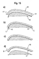
- the fiber layer 31a consists of fibers (rovings) 33 which have been deposited in this axial direction.
- the same workpiece carrier 40 is shown, on which a second fiber layer 32b has been deposited over the first fiber layer 31a.
- the fibers of the second fiber layer 31b have an orientation of -45 ° relative to the orientation of the first fiber layer 31a.
- a third fiber layer 31c is deposited over the second fiber layer 31b, wherein it was deposited only on a part of the workpiece carrier 40.
- the third Layer 31c has an orientation of + 45 ° relative to the first layer 31a and thus of 90 ° relative to the second layer 31b.
- the three layers 31a to 31c form a multilayer, multi-axial fiber architecture (MAFA) 31.
- MAFA multilayer, multi-axial fiber architecture
- the fibers 33 are deposited dry on the workpiece carrier 40.
- workpiece carrier results in that this could lead to difficulties in the upstanding rounding.
- Something similar could arise in a situation like that in Fig. 3a is shown.
- a workpiece carrier 40 is shown, whose shape essentially corresponds to a circular cylinder cut through in the middle in the axial direction.
- FIG. 3b An example of such intermediate fixation is shown schematically in FIG Fig. 3b ).
- Fig. 3c is shown in a plan view of a workpiece carrier, as the in Fig. 3a ) is formed, but on its upper side has a protruding projection, around which the fibers 33 are to be placed. As it turned out Fig. 3c ), it should be done in this area, an intermediate fixation of dry laid fibers.
- FIG. 4 First embodiments for the provision of such intermediate fixing areas are shown.
- Fig. 4 is shown schematically a cross-sectional view of a workpiece carrier 40 having a hollow interior 40h.
- the hollow interior 40h can be connected to a pump via a pump connection 40p.
- through-holes 401 are formed in the wall 40w on which the fibers 33 are to be deposited.
- the inner space 40h is maintained at a pressure pi smaller than the atmospheric pressure pu by connecting a corresponding pump.
- a negative pressure or a suction effect is produced on the outer side of the wall 40w, so that the deposited fibers 33 are temporarily fixed in this edge fixing region, which is designed as a negative pressure / suction region 43c.
- FIG. 4b another embodiment of an intermediate fixing portion 43 is shown, which is formed as a needle portion 43d. In this area of the needles, there are needles 43n on the outside of the wall 40w, by means of which the fibers 33 are temporarily fixed.
- intermediate fixing areas e.g. as areas for applying an adhesive or for providing hooks or for freezing the fibers are also possible.
- Fig. 5 a partial cross-sectional view of a wall 40w of a workpiece carrier 40 is shown. Subsequent to the workpiece standard region 41, the edge fixing region 42 is formed. This is maintained at a temperature substantially lower than the freezing point of a fixing medium (eg water). Much lower here means temperature differences of 10K and more, in the case of water about 30K.
- the cooling of the fixing region can, for example, pass through the passage of a cold liquid cooling medium through cooling channels in the fixing region.
- a cold liquid cooling medium through cooling channels in the fixing region.
- the liquefied, low-viscosity fixing medium to the point at which the fibers 33 are to be fixed in Randfixier Scheme 42, sprayed. Due to the large temperature difference, the fixing medium freezes instantaneously and thereby the fiber to be fixed 33 is frozen at the Vereisunss Scheme 43b.
- This fixation method is of course also, as previously described, applicable to the intermediate fixation. Fixiermiedien, which are not low viscosity at room temperature, must be promoted hot to the spray nozzle.
- FIG. 6a an edge fixation of fibers 33 is shown by means of mechanical clamping.
- Holding elements 42h are provided in the edge fixing region 42, which apply a clamping force perpendicular to the edge fixing region and thus clamp the fibers 33.
- the clamping force can be applied by a pneumatically, electrically or hydraulically driven kinematics or eg by using magnetic clamping elements, which are attracted to the Randfixier Scheme 42.
- controllable electromagnets could be provided in the edge region.
- FIG. 6b an alternative embodiment of a mechanical clamping system for the edge fixing area is shown.
- Two rows of clamping hooks 42k are used.
- the clamping hooks which is not shown, are displaced upwards out of the plane of the edge fixing area and thereby rotated, so that the fibers 33 are laid dry and then clamped by twisting and pulling down the hooks 42k.
- the clamped state is shown in Fig. 6d.
- FIG. 7a For example, an embodiment of the edge fixing portion 42 in which needles 42n project from the edge fixing portion 42 is shown.
- Fig. 7b again shows an embodiment in which hooks 42k are used for edge fixing.
- Fig. 6 For example, the use of the edge fixing area such that the fibers 33 are cut off after the edge fixing is shown.
- Fig. 7 the use of the embodiments of the edge fixing areas is shown such that the fibers are not cut off after the edge fixing but the fiber pattern is continued at this point without cutting off the fibers.
- Fig. 8 is shown schematically how using the workpiece carrier 40 and the laying head 20, an edge fixation by means of adhesive KS is obtained in the Randfixier Scheme 42.
- Fig. 8a is shown from top to bottom of the sequence with a laying head 20 with integrated adhesive nozzle 22.
- the fiber bundle 30 supplied from the top right into the laying head 20 is deposited on the workpiece carrier 40 via a contact / deflection roller 22.
- the dry fibers 33 of the fiber bundle 33 are first deposited on the workpiece molding area 41.
- the read head 20 has an integrated cutting mechanism 21 with which the fibers 33 of the fiber bundle 30 can be cut off. Details of such cutting mechanisms will be explained later.
- a position is shown schematically in which the length of the fiber from the current depositing point on the workpiece carrier 40 to the cutting mechanism corresponds to the remaining laying length to the end of the edge fixing area 42.
- the fibers 33 of the fiber bundle 30 are first cut by operating the cutting mechanism 21, as indicated schematically by the arrow.
- adhesive KS is applied in a corresponding length by the integrated adhesive nozzle, so that after moving the laying head 20 in the position, the in Fig. 8a ), shown below, the cut fibers 33 of the bundle of fibers 30 are fixed in the edge fixing region 42 by the adhesive KS applied only in sections.
- Fig. 8b substantially the same procedure is shown for an embodiment in which the adhesive nozzle 6 is provided as an external adhesive nozzle 49 instead of the internal adhesive nozzle 22.
- the adhesive is not applied to the fibers 33 of the fiber bundle 30 but onto the corresponding section of the edge fixing region 42.
- a first embodiment of a cutting mechanism 21 for the laying head 20 is shown.
- the cutting mechanism 21 has a pusher 210 and an abutment 220.
- the pusher 210 and the abutment 220 are spaced from each other.
- a fiber passage or fiber passage 250 is formed between the pusher 210 and the rear bearing 220.
- the pusher 210 is movable perpendicular to the fiber advancing direction relative to the abutment 220, as can be seen from the comparison of the views a1) and a2).
- a cutting blade 230 is provided so as to be movable perpendicular to the fiber feeding direction V.
- the cutting blade 230 is biased by a spring 233 in the direction away from the fibers 33.
- the pusher 210 is moved in the direction of the abutment 22 by an actuator, not shown, and pressed with a clamping force F K against the abutment and with this clamping force to be cut fiber 33 is clamped between the jaws 211, 221. This condition is shown in view a2).
- the cutting knife becomes 230 against the biasing force of the spring 233 by an actuator with a cutting force Fs pressed against the fiber to be cut 33 and the jammed between the jaws 211, 221 fiber is cut or broken.
- the cutting blade 230 flanks 231, 233 of the cutting edge, which are at an angle of approximately 90 ° to each other. That is, the blade angle is 90 ° (the preferred value from a range of 45 to 120 °).
- the cutting operation of a fiber 30 and such a "blunt" blade is called stretch breaking.
- the fiber is bent under high tension over an edge, ie the blade.
- the combination of tensile stress and bending stress and the brittleness of the material of the fiber causes the fiber to break.
- This cutting method is only suitable for brittle fibers such as carbon fibers or glass fibers.
- the advantage of the large blade angle is that the cutting edge / breaking edge is therefore very robust and the wear is extremely low. No relative movement between blade and fibers is needed. And no counter surface is needed for cutting, which could damage the breaking edge.
- pinching the fiber between the jaws 211, 221 both allows for stretch breaking and prevents the transmission of tensile stress to the fibers 33 of a fiber bundle.
- FIG. 9a schematically drawn principle of a cutting mechanism 21 for stretch breaking is feasible in various embodiments.
- pusher 210 and cutting blade 230 which may be mechanical or hydraulic or pneumatic drives or combinations of pneumatic, hydraulic and mechanical drives of the two elements.
- the pusher 210 could be stationary and the abutment 220 could be moved toward the pusher 210.
- the pusher 210 may be pneumatically accelerated, and the cutting blade 230 is resiliently mounted in the pusher 210.
- FIG. 9b another embodiment of the cutting mechanism 21 is shown, with which the principle of the bending breaking is realized.
- a sharper blade of the cutting blade ie a significantly smaller cutting angle than during bending
- the fiber against an elastic pad 222 which is applied to the abutment 220, pressed.
- the underlay is formed by the impression of the blade around the blade.
- the fibers between blade and pad are bent by the small cutting radius of the blade. Due to the brittleness of the fibers, they break from blade to backing even at low pressure forces.
- Blade and base wear not or only slightly, if the shearing force is limited to the degree just necessary, since here, too, no relative movement between the blade, pad and fibers to be cut occurs through which abrasive wear can occur
- the cutting knife 240 can turn pneumatically, hydraulically , mechanical etc. are moved.
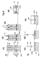
- Fig. 10 shows various possibilities of generating the relative movement of laying head 20 and workpiece carrier 40.
- FIG. 10a shown Aus Strukturbrungsform the workpiece carrier 40 is held on a fixed support 15 for the workpiece carrier.
- the robot 10 moves the laying head 20 during the storage of the fiber bundle.
- a manipulator 16 could be provided for the workpiece carrier 40 ( Fig. 10b )), which moves the workpiece carrier relative to the laying head 20 which is held on a laying head holder 11.
- a combination with robot 10 and manipulator 16, as it is in Fig. 10c ) is possible.
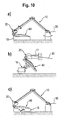
- Fig. 11 It is schematically shown how the fibers 33 are supplied to the fiber bundle 30 during the depositing operation.
- the fibers (rovings) 33 are wound on spools 51 of a fiber feeding mechanism 50 and are fed from there to the laying head 20 via parts of the fiber feeding mechanism 50 to be described later.
- the arrangement of the deflection of the fiber feed mechanism at the joints of the manipulator system it is possible to keep the distance of the fiber bundle from the coil to the laying head constant. As a result, a loosening and associated sagging of the fiber bundle is avoided during movements of the manipulator system.
- Fig. 12 shows a first embodiment of a fiber guiding mechanism 52 of a fiber feeding mechanism 50.
- the fiber guiding mechanism 52 is implemented in the form of a modified energy chain, which is a form of a fiber guiding chain.
- Energy chains are known in engineering to guide flexible cables or pneumatic or hydraulic lines connected to a machine part that is constantly moving.
- a fiber guide chain consisting of several mutually pivotable segments, which can be produced for example by modification of an energy chain.
- the energy chain is modified in such a way that rotating waves guide the fibers, as in Fig. 12 is shown.
- Such a fiber guide chain 52 has chain segments 52s. Adjacent chain segments 52s may rotate relative to one another about an axis 52a. This means that the distance between two adjacent axes 52a remains constant.
- 52a rotatably mounted shafts 52w are set on each axle. That is, the revolving shafts 52w extend along the axial direction of the shafts 52a.
- the fibers 33 in the fiber advancing direction V are always passed alternately left and right on the shafts 52w.
- plan view of the fiber bundle 33 this means that the fiber bundle 33 is guided in the fiber advance direction V alternately under and over the shafts 52w.
- the distance of the adjacent shafts 52w remains constant at a bend of the fiber guide chain 52 that substantially no pulling force is applied to the guided fibers 33 or the fiber bundle 30 by a movement of the fiber guide chain. Due to the guidance of rotatably mounted shafts, for example, by the leadership omitted Hoses occurring frictional forces. As a result, less force is needed to pull off the roving blade and the fibers are guided without damage.
- fibers can also be guided three-dimensionally in space.
- this embodiment of a fiber guide chain also enables the guidance of tape-like, textile reinforcements such as narrow-band fabrics and fabric tapes.
- Fig. 13 shows a second embodiment of a fiber guide chain.
- the second embodiment differs from the first embodiment in that separate rollers rotatably mounted on the shafts 52w are provided for the fibers (rovings) 33. With this arrangement, it is possible to feed each fiber at an individual speed through the fiber guide chain.
- the reading head 20 has a fiber conveying device, not shown.
- the fiber conveying can eg with a conveyor unit, as in the US 2009/0229760 A1 is described, be realized.
- a fiber extraction according to the Eytelwein principle is known.
- This Eytelwein principle has long been used in sewing and knitting systems for fiber composites.
- the fiber conveying mechanism is used to compensate for the fiber forces caused by friction in the fiber guide or the fiber feed.
- the fibers run over two rows of rollers, which are arranged parallel to one another and offset.
- the rollers rotate under the rovings without conveying them, i. with slippage. If tensile forces are applied to the rovings, e.g. arise at the pulleys and the like, the fibers are conveyed by the rotating rollers.
- a device for processing the fibers can be provided in the laying head.
- the fibers can be brought to a defined width by means of spreading (preparation).
- all fibers can be combined into a uniform, homogeneous band of defined width (Homogenization).
- the goal here is that there are no gaps between the fibers of the fiber bundle and also no overlaps between the fibers of the fiber bundle.
- targeted gaps or overlaps could be made.
- the width of the fiber bundle can be varied at the output of the read head and it is possible to vary the basis weight of the fiber bundle.
- the fiber preparation can be done by rollers, rollers, mandrels and the like.
- a fiber conditioning device is provided which can bring the fibers of the fiber bundle to a defined width and / or the distances of the fiber of the fiber bundle can vary.
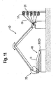
- Fig. 14 is shown schematically the process of transferring a built preform of the workpiece carriers in the subsequent processing step.
- the workpiece carrier 40 is formed in the embodiment shown with a hollow interior 40h, and the interior 40h can be connected via a port 40p to a pump or pressure source.
- the preform 31 in the form of a MAFA has been constructed by depositing a plurality of fiber bundles in accordance with a fiber laying pattern.
- the transfer device 60 whose shape at the bottom corresponds to the outer shape of the preform 31, is lowered in the direction of the arrow A on the workpiece carrier 14.
- a pressure p1 equal to or greater than the ambient pressure pu is applied to the port 40p of the workpiece carrier 40, while at a pressure port 60p of the transfer unit 60, a negative pressure p2 smaller than the atmospheric pressure pu is applied.
- the preform 31 is sucked on the transfer unit 60, while the suction effect on the workpiece carrier 40, which was used for intermediate fixing and / or edge fixing is canceled.
- the preform 31 can then be lifted from the workpiece carrier while maintaining the negative pressure p2, as in FIG Fig. 14c ) (movement of the transfer device 60 in the direction of the arrow B).
- the transfer device 60 that is, the finished preform 21, unloads from the workpiece carrier 40 and transfers (transfers) it, for example, into a mold for injecting resin and for curing.
- the preform can be brought to an intermediate storage or to another processing station.
- the "gripping" of the finished preform 31 can not only by vacuum but also mechanically. e.g. by clamps, needles, electrostatic or magnetic holders, etc. or by freezing or gluing, as previously described.
- the transfer device also gives the opportunity to drape the preform, as described below.
- the transfer device also gives the opportunity to package the finished preform between two layers of resin films or films and / or to perform a shape fixation.
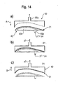
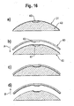
- Fig. 15 and 16 Possibilities of forming (draping) the finished preform 31 by means of the transfer device 60 are shown.
- Fig. 15 First, an embodiment is shown, with which the edge region of the preform 31 can be draped.
- the workpiece carrier 40 has for this Drapierrand Schemee 45 which are movable in the direction of arrows C (see Fig. 15b )).
- the transfer device 60 is lowered onto the workpiece carrier 40 with the finished preform 31.
- the draping edge portions 45 are moved to drape the edge of the finished preform 31, and then the preform 31 draped in the edge portion is removed from the workpiece carrier 40 by means of the transfer device 60.
- Fig. 16 an embodiment for draping another area is shown.
- an insert 46 is inserted into a recess 47.
- the preform 31 is finished on the workpiece carrier 40 ( Fig. 16a )) before the transfer unit 60 is lowered onto the workpiece carrier 40.
- the insert 46 is removed, so that the recess 47 is present under the finished preform 31.
- the transfer device 60 has a draping projection 62 that is complementary to the recess 47.
- draping means 45, 46, 47, 62 interacting with the transfer device 60 and the workpiece carrier 40 are provided for draping the finished preform 31.
- Fig. 17 shows how a packaging or shape fixing of the preform 31 by means of films 70 or resin films 71 is possible.
- a film 70 or a resin film 71 is deposited on the workpiece carrier before the fiber layers 30/33 are deposited.
- resin films 71 can also be deposited between some fiber layers. After depositing the last fiber layer, a film 70 or a resin film 71 is applied. The outer films 70 or the outer resin films 71 are now connected to each other airtight and then the air is sucked between the films through an exit 72.
- the films and the resin films can be prefabricated, flat, two- or three-dimensionally shaped thermoplastic and / or thermosetting resin films or thermoplastic and / or duromeric films. However, they can also be formed by coating a flat resin film or film over the fiber layers similar to a deep-drawing process or, for example, by spraying resin or a suitable polymer onto the fiber layers.
- hybrid fibers may be used which include thermoplastic and / or thermosetting polymer fibers in addition to the reinforcing fiber.
- the outermost or the outermost films may also be functional films which serve, for example, for the realization of high surface qualities equivalent to a lacquer.
- a preform with or without resin films can also be placed in a prefabricated foil pouch and / or tubular foil section, the open edges of which are subsequently closed.
- this "packaging" is advantageous since the application of negative pressure can stabilize the shape of the preform for intermediate storage or transport.
- Fibers, resin films and films form a transpont-stable and easy-to-store unit, which allow curing in a simple hot pressing device. Due to the shorter flow paths of the resin, the impregnation of the preform is shortened and thus also the tool occupancy time. Furthermore, the fiber distortion occurring during resin injection processes is avoided by flow processes during filling of the mold cavity.
- a further advantage consists in the simple handling of such packaged dry preforms of fiber layers and / or semi-finished layers, since these are e.g. can be handled automatically with simple vacuum grippers.
- the "packaging" of the preform can facilitate subsequent forming since e.g. the drape capability of the preform can be selectively influenced by the strength of the enclosed vacuum and / or the fixing of edges or edge portions of the packaging.
- Flat is to be understood in a planar or sheet-like manner in the sense that essentially a surface-forming component is meant whose extent perpendicular to its surface is small compared to the extent along its surface, e.g. at least 1: 4 or 1: 5 or 1: 6 or 1: 7 or 1: 8 or 1: 9 or 1:10 or ....... or 1: 100 or 1: 101 or bib or 1: 200 or .... etc.
- the outer layers films or resin films
- the outer layers are advantageously designed to be airtight, so that the application of the negative pressure, ie the evacuation of the gap is possible.
- the preform to be packaged must, as already described in the description of the packaging or mold fixing of the preform 31 by means of films 70 or resin films 71 for Fig. 17 shows, not necessarily be made by means of the device described.
- the usage of multi-axial, woven fabrics, etc. for the formation of the preform, as above for Fig. 17 is packaged or form-fixed, is just as possible.
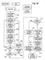
- step S1a a resin film or a film may be placed on the workpiece carrier as described, for example, with reference to FIG Fig. 17 has been described. This step S1a is optional.
- step S2 the fibers of the fiber bundle are fixed at the beginning of a laying web.
- the edge region may also designate a fixing region on an inner edge of a component or workpiece carrier if the component has a larger, non-fibrous cut-out, such as e.g. a window or manhole.
- the laying web then to be lowered in step S3 is predefined in a fiber laying pattern.
- the fibers are temporarily fixed.
- the fibers of the fiber bundle are fixed in the edge fixing area (S4).
- the fibers of the fiber bundle are optionally cut off behind the edge fixing (step S4a). Such a process is exemplary in Fig. 8 been shown.
- step S5 it is checked whether the position corresponding to the laying pattern is complete or not. If the situation has not yet been completely filed, it is jumped to step S2, in which the fiber bundle is fixed at the beginning of the now to be driven laying web for the situation. If the laying track continues at the same place (see eg Fig. 7 , this fixation has already been carried out by executing the previous step S4)
- step S6 it is checked in step S6 whether the preform has been completely laid. If not, in step S6a optionally a resin film placed on the laid layer (see, eg Fig. 17 ) and optional local gains are applied in step S6b, and then the flow advances to step S2. The steps S2 to S6b are repeated in the described form until the preform has been completely deposited. In this case, the determination in step S6 indicates YES, so that the flow advances to step S7. In step S7, it is checked if previously resin films or foils have been underlaid. Laying / applying one or more local inlays (eg blanks of fabric or scrim, prefabricated knits, ribbons) onto the preform or between the layers of the preform in step 6b results in the formation of localized reinforcements.
- one or more local inlays eg blanks of fabric or scrim, prefabricated knits, ribbons
- step S7 If the check in step S7 is NO, then the portions of the fibers in the edge fixing area are separated from the preform, e.g. by cutting (step S8). This gives the preform the desired shape. Clipping the fixation area is optional. It may also be advantageous to leave the fixing area on the preform (better preform stability.) The fixing area may for example serve as a pinch edge in the resin injection tool.
- step S9 the preform is removed from the workpiece carrier. This can be done, for example, as it is in the Fig. 14 to 16 was shown. After being removed in step S9, the detached preform is transferred in a curing mold or in an intermediate storage or to another processing step (S 14). Between steps S6 and S8, optional draping steps may be provided.
- step S10 a resin film or a film is placed on the preform located on the workpiece carrier. Then, in step S11, the upper and lower resin films are sealed against each other, and in step S12, a negative pressure for stabilizing the preform is applied. Then, in step S13, the stabilized preform is detached from the workpiece carrier and the process proceeds to step S14 already described.
Description
Die vorliegende Erfindung bezieht sich auf eine Faserrührungsvorrichtung und eine Verwendung einer Faserführungsvorrichtung und eine Vorrichtung zum Aufbau eines dreidimensionalen Vorformlings für ein Bauteil aus einem Faserverbundwerkstoff.The present invention relates to a fiber stirring device and a use of a fiber guiding device and a device for constructing a three-dimensional preform for a component made of a fiber composite material.
Faserverbundwerkstoffe werden aufgrund ihrer Materialeigenschaften häufig in Leichtbaukonstruktionen eingesetzt. Zur Herstellung von Bauteilen aus Faserverbundwerkstoffen existieren eine Vielzahl unterschiedlicher Fertigungsverfahren, die sich vor allem durch die dabei verarbeiteten Halbzeuge (vorgefertigte Rohmaterialformen), unterscheiden. Im Bereich der Faserverbundwerkstoffe wird allgemein zwischen mit Harz vorimprägnierten Halbzeugen, auch Prepreg, abgeleitet von "preimpregnated" bezeichnet, und trockenen Halbzeugen unterschieden. Das Ausgangsmaterial für beide Arten von Halbzeugen für Faserverbundwerkstoffe sind dabei sogenannte Rovings. Ein Roving ist ein Faden, der aus einer Mehrzahl von Filamenten aus dem Faserwerkstoff besteht, die man als die eigentlichen Fasern bezeichnen könnte. Für Faserverbundwerkstoffe werden bevorzugt Kohlenstofffasern, auch Karbonfasem genannt, Glasfasern, Aramidfasern, etc. verwendet. Ein solches Roving kann aus einigen wie z.B. 8 oder 10 Filamenten bis zu z.B. 50000 Filamenten oder mehr bestehen. In dieser Anmeldung bezeichnet der Begriff Faser ein Roving, außer wenn ausdrücklich auf einzelne Filamente Bezug genommen wird.Fiber composites are often used in lightweight constructions due to their material properties. For the production of components made of fiber composite materials, there are a large number of different production methods, which differ, in particular, from the semifinished products (prefabricated raw material forms) processed thereby. In the field of fiber composites, a distinction is generally made between semi-finished products pre-impregnated with resin, also known as prepreg, derived from "pre-impregnated", and dry semi-finished products. The starting material for both types of semi-finished products for fiber composites are so-called rovings. A roving is a thread that consists of a plurality of filaments of fiber material that could be called the actual fibers. For fiber composites, carbon fibers, also called carbon fibers, glass fibers, aramid fibers, etc. are preferably used. Such a roving may consist of some such as e.g. 8 or 10 filaments up to e.g. Consist of 50,000 filaments or more. In this application, the term fiber refers to roving, unless express reference is made to individual filaments.
Die sogenannten Prepregs können auf unterschiedliche Art und Weise hergestellt werden. Zum Beispiel können trockene Faserhalbzeuge mit einem duromeren Harz, das bei Raumtemperatur eine hochviskose, klebrige Konsistenz aufweist, getränkt werden. Es existieren auch Faserhalbzeuge, die mit einer Harzmatrix aus thermoplastischem Kunststoff imprägniert sind. Beide Formen werden im Rahmen dieser Anmeldung als Prepregs bezeichnet.The so-called prepregs can be produced in different ways. For example, dry semifinished fiber products may be impregnated with a thermosetting resin having a high viscosity, sticky consistency at room temperature. There are also semi-finished fiber products which are impregnated with a resin matrix of thermoplastic material. Both forms are referred to in this application as prepregs.
Diese Halbzeuge können als meist parallele, unidirektionale Fasern, auch UD-Prepreg genannt, oder Gewebe, auch Gewebe-Prepreg genannt, vorliegen.These semi-finished products can be present as mostly parallel, unidirectional fibers, also called UD prepreg, or tissue, also called tissue prepreg.
Auch bei den trockenen Halbzeugen gibt es im Stand der Technik verschiedene Formen. Eine wichtige Art von trockenen Halbzeugen sind neben Geweben die Gelege, die in der Regel als Multiaxialgelege (MAG) aus mehreren aufeinandergelegten Lagen von Fasern mit verschiedenen Orientierungen bestehen, die z.B. durch Vernähen oder mittels eines Binder genannten Klebstoffs zusammengehalten werden. Multiaxialgelege können unidirektional (UD), biaxial, z.B. in zwei Lagen, triaxial, z.B. in drei Lagen, quadriaxial, z.B. in vier Lagen, usw., d.h. mit entsprechender Anzahl verschieden orientierter Lagen, hergestellt werden. Weitere trockene Halbzeuge sind Gestricke, Geflechte, Gewirke, Schmalbandtextilien und Rovings. Die Rovings stellen das Ausgangsmaterial für alle Halbzeuge dar. Der Faserverbundwerkstoff für ein Faserverbundbauteil weist immer die beiden Komponenten Verstärkungsfaser und Matrix (Harz) auf. Die beiden Komponenten Verstärkungsfaser und Matrix (Harz) müssen in den Fertigungsvorgängen zusammengeführt werden.Even with the dry semi-finished products, there are various forms in the prior art. An important type of dry semi-finished products are, in addition to tissues, the clutches, which as a rule Multiaxial Layers (MAG) consist of several successive layers of fibers with different orientations, which are held together, for example, by sewing or by means of a binder called adhesive. Multiaxial layers can be produced unidirectionally (UD), biaxially, eg in two layers, triaxially, eg in three layers, quadriaxially, eg in four layers, etc., ie with a corresponding number of differently oriented layers. Other dry semi-finished products are knits, braids, knitted fabrics, narrow-band textiles and rovings. The rovings represent the starting material for all semi-finished products. The fiber composite material for a fiber composite component always has the two components reinforcing fiber and matrix (resin). The two components reinforcing fiber and matrix (resin) must be merged in the manufacturing processes.
Im Falle der Prepregs, d.h. der Halbzeuge mit duromeren und thermoplastischen Beschichtungen, Imprägnierungen, etc. liegen die Verstärkungsfaser und die Matrix in bereits gemischter Form vor. Bei den Prepregs wird die Matrix nach den formgebenden Herstellungsschritten, die zur gewünschten Bauteilgeometrie führen, unter Temperatur und/oder Druck in einem Autoklaven ausgehärtet.In the case of prepregs, i. Semi-finished products with duromeric and thermoplastic coatings, impregnations, etc. are the reinforcing fiber and the matrix in already mixed form. In the case of the prepregs, the matrix is cured under temperature and / or pressure in an autoclave after the shaping production steps which lead to the desired component geometry.
Beim sogenannten Vorformen (Preforming) wird unter Verwendung von trockenen Halbzeugen ein Vorformling (Preform) in der gewünschten Bauteilgeometrie hergestellt. Die Imprägnierung mit z.B. dem duromeren Harz erfolgt danach mittels eines Injektionsverfahrens oder eines Infusionsverfahrens. Dabei wird das Harz mit Überdruck in das trockene Halbzeug in Bauteilgeometrie gepresst oder unter Verwendung von Unterdruck in das in Bauteilgeometrie befindliche Halbzeug infiltriert.In so-called preforming (preforming), a preform (preform) in the desired component geometry is produced using dry semi-finished products. Impregnation with e.g. the thermosetting resin is then carried out by means of an injection method or an infusion method. In this case, the resin is pressed with overpressure in the dry semi-finished product in component geometry or infiltrated using vacuum in the semifinished product located in the component geometry.
Es können also im Stand der Technik drei gängige Herstellungsverfahren für dreidimensionale Bauteile aus Faserverbundwerkstoffen unterschieden werden. Als erstes das Vorformen (Preforming), bei dem ein Bauteilvorformling (Preform) aus Gewebezuschnitten und/oder Multiaxialgelegezuschnitten lagenweise aufgebaut und anschließend in einer Form mit Harz imprägniert und ausgehärtet wird. Zweitens das Herstellen des Bauteils aus Prepreg-Zuschnitten, die lagenweise in einer Form abgelegt und anschließend ausgehärtet werden. Drittens, das Faserlegeverfahren, bei dem eine oder mehrere Fasern z.B. automatisiert auf einer Form abgelegt werden. Dabei können Prepreg-Fasern verwendet werden, wie es z.B. in der
Aus der
Alle diese Verfahren sind im Hinblick auf die Herstellung von dreidimensionalen Bauteilen aus Faserverbundwerkstoffen nicht befriedigend. Es gibt verschiedene Nachteile wie z.B. große Verschnittanteile der ursprünglichen Halbzeuge und/oder hohe Anteile an Handarbeit und/oder niedrige Produktionsgeschwindigkeiten bei Automatisierung und/oder Probleme mit der Materiallagerung und/oder Probleme bei der Imprägnierung mit der Matrix.All of these methods are unsatisfactory with regard to the production of three-dimensional components from fiber composites. There are several disadvantages, such as large blending proportions of the original semi-finished products and / or high levels of manual labor and / or low production speeds in automation and / or problems with material storage and / or problems with impregnation with the matrix.
Es ist daher eine Aufgabe der Erfindung, eine verbesserte Technik zur Herstellung von dreidimensionalen Vorformlingen für Bauteile aus Faserverbundwerkstoffen anzugeben.It is therefore an object of the invention to provide an improved technique for the production of three-dimensional preforms for components made of fiber composites.
Diese Aufgabe wird gelöst durch eine Faserführungsvorrichtung nach Anspruch 1 bzw. eine Verwendung nach Anspruch 4 bzw. eine Vorrichtung nach Anspruch 5.This object is achieved by a fiber guiding device according to claim 1 or a use according to claim 4 or a device according to
Weiterbildungen der Erfindung sind in den Unteransprüchen angegeben.Further developments of the invention are specified in the subclaims.
Weitere Merkmale und Zweckmäßigkeiten ergeben sind aus der Beschreibung von Ausführungsbeispielen anhand der Figuren. Von den Figuren zeigen:
- Fig. 1
- eine perspektivische Ansicht eines Werkstückträgers und eines Roboters mit Legkopf;
- Fig. 2
- in (a) eine Ansicht eines Werkstückträgers, und in (b), (c) und (d) mit abgelegten Faserlagen;
- Fig. 3
- in (a) einen Werkstückträger mit darauf abgelegten Fasern ohne Zwischenfixierung, und in (b) und (c) einen Werkstückträger mit darauf abgelegten Fasern mit Zwischenfixierungsbereichen nach Ausführungsformen der Erfindung;
- Fig. 4
- in Querschnittsansichten Ausführungsformen von Werkstückträgern mit Zwischenfixierungsbereichen, in (a) mit Ansaugzwischenfixierungsbereichen und in (b) mit Nadelzwischenfixierungsbereich;
- Fig. 5
- eine ausschnittsweise Querschnittsansicht einer Ausführungsform eines Werkstückträgers mit einem Vereisungsrandfixierungsbereich;
- Fig. 6
- Ausführungsformen von Randfixierungsbereichen eines Werkstückträgers, in a) als Randfixierungsbereich mit mechanischen Klemmen (Kinematik der Klemmvorrichtung nicht gezeigt) und in b) als Hakenrandfixierungsbereich;
- Fig. 7
- Ausführungsformen von Randfixierungsbereichen eines Werkstückträgers, in a) als Nadelrandfixierunesbereich und in b) als Hakenrandfixierungsbereich;
- Fig. 8
- Querschnittsansichten des Ablegens, Randfixierens und Abschneidens von Fasern, in a) mit in dem Legekopf integrierten Klebestoffauftrag, und in b) mit externem Klebstoffaufrag für die Randfixierung;
- Fig. 9
- Ausführungsformen von Faserschneidmechanismen;
- Fig. 10
- schematische Ansichten verschiedener Ausführungsformen zur Realisierung der Relativbewegung von Legekopf und Werkstückträger;
- Fig. 11
- eine schematische Ansicht zur Erläuterung der Faserzufuhr;
- Fig. 12
- eine erste Ausführungsform einer modifizierten Energiekette für die Faserführung, in a) in einer Schnittansicht und in b) in einer teilweise aufgeschnittenen perspektivischen Ansicht;
- Fig. 13
- eine zweite Ausführungsform einer modifizierten Energiekette für die Faserzuführung, in a) in einer Schnittansicht und in b) in einer teilweise aufgeschnittenen perspektivischen Ansicht;
- Fig. 14
- schematische Darstellungen in Querschnittsansicht einer Ausführungsform einer Transfervorrichtung, die in und a) bis c) das Abnehmen des Vorformlings von dem Werkstückträger mittels der Transfervorrichtung zeigt;
- Fig. 15
- schematische Darstellungen in Querschnittsansicht einer zweiten Ausführungsform einer Transfervorrichtung, die in a) bis d) das Abnehmen des Vorformlings von dem Werkstückträger mittels der Transfervorrichtung zeigt;
- Fig. 16
- schematische Darstellungen in Querschnittsansicht einer dritten Ausführungsform einer Transfereinheit und a) bis d) den Ablauf des Abnehmens des Vorformlings von dem Werkstückträger mittels der Transfervorrichtung;
- Fig. 17
- eine schematische Darstellung einer Vakuumstabilisierung eines Vorformlings und Einbringen von Harzfilmen nach einer Ausführungsform der Erfindung;
- Fig. 18
- eine Ablaufdarstellung eines Herstellungsverfahrens nach einer Ausführungsform der Erfindung; und
- Fig. 19
- eine schematische Darstellung einer Ausführungsform einer Technik zum Einbringen von Lücken in Rovings/Fasern einer Faserschar.
- Fig. 1
- a perspective view of a workpiece carrier and a robot with Legkopf;
- Fig. 2
- in (a) a view of a workpiece carrier, and in (b), (c) and (d) with deposited fiber layers;
- Fig. 3
- in (a) a workpiece carrier with fibers deposited thereon without intermediate fixing, and in (b) and (c) a workpiece carrier with fibers deposited thereon with intermediate fixing regions according to embodiments of the invention;
- Fig. 4
- In cross-sectional views embodiments of workpiece carriers with Zwischenfixierungsbereichen, in (a) with Ansaugzwischenfixierungsbereichen and in (b) with Nadelzwischenfixierungsbereich;
- Fig. 5
- a partial cross-sectional view of an embodiment of a workpiece carrier with a glazing edge fixing area;
- Fig. 6
- Embodiments of edge fixing areas of a workpiece carrier, in a) as an edge fixing area with mechanical clamps (kinematics of the clamping device not shown) and in b) as a hook edge fixing area;
- Fig. 7
- Embodiments of edge fixing areas of a workpiece carrier, in a) as Nadelrandfixierunesbereich and in b) as Hakenrandfixierungsbereich;
- Fig. 8
- Cross-sectional views of depositing, edge fixing and cutting of fibers, in a) with integrated in the laying head adhesive application, and in b) with external adhesive application for edge fixation;
- Fig. 9
- Embodiments of Fiber Cutting Mechanisms;
- Fig. 10
- schematic views of various embodiments for the realization of the relative movement of laying head and workpiece carrier;
- Fig. 11
- a schematic view for explaining the fiber supply;
- Fig. 12
- a first embodiment of a modified energy chain for the fiber guide, in a) in a sectional view and in b) in a partially cutaway perspective view;
- Fig. 13
- a second embodiment of a modified fiber supply energy chain, in a) in a sectional view and in b) in a partially cutaway perspective view;
- Fig. 14
- schematic representations in cross-sectional view of an embodiment of a transfer device, which shows in and a) to c) the removal of the preform from the workpiece carrier by means of the transfer device;
- Fig. 15
- schematic representations in cross-sectional view of a second embodiment of a transfer device, showing in a) to d) the removal of the preform from the workpiece carrier by means of the transfer device;
- Fig. 16
- schematic representations in cross-sectional view of a third embodiment of a transfer unit and a) to d) the sequence of removing the preform from the workpiece carrier by means of the transfer device;
- Fig. 17
- a schematic representation of a vacuum stabilization of a preform and introducing resin films according to an embodiment of the invention;
- Fig. 18
- a flow chart of a manufacturing method according to an embodiment of the invention; and
- Fig. 19
- a schematic representation of an embodiment of a technique for introducing gaps in rovings / fibers of a fiber bundle.
Zunächst werden einige allgemeine Erläuterungen zu den gelehrten Vorrichtungen und Verfahren gegeben, bevor spezifische Ausführungsformen beschrieben werden.First, some general explanations will be given to the taught devices and methods before describing specific embodiments.
Mit den gelehrten Vorrichtungen und Verfahren ist es möglich, trockene Fasern (Rovings) in einer Faserschar auf einem Werkstückträger abzulegen. Die trockenen Fasern werden in einem dafür vorgesehenen Randbereich des Werkzeugträgers fixiert (Randfixierung) und, abhängig von der dreidimensionalen Geometrie des zu erstellenden Vorformlings, gegebenenfalls in bestimmten Zwischenfixierbereichen zwischenfixiert.With the learned devices and methods, it is possible to deposit dry fibers (rovings) in a fiber bundle on a workpiece carrier. The dry fibers are fixed in an edge region of the tool carrier provided for this purpose (edge fixation) and, depending on the three-dimensional geometry of the preform to be produced, optionally fixed in certain intermediate fixing areas.
Dies führt dazu, dass zum Einen wesentlich kostengünstigere trockene Fasern für den Aufbau des dreidimensionalen Vorformlings verwendet werden können, und andererseits aufgrund des Ablegens der trockenen Fasern hohe Vorschubgeschwindigkeiten erzielt werden können.As a result, on the one hand, substantially less expensive dry fibers can be used for the construction of the three-dimensional preform, and on the other hand high feed rates can be achieved due to the laying down of the dry fibers.
Es werden verschiedene Vorrichtungen im Verfahren zur Randfixierung und zur Zwischenfixierung gelehrt, die abhängig von der dreidimensionalen Gestalt des aufzubauenden Vorformlings gewählt werden können.Various devices are taught in the method of edge fixation and intermediate fixation, which can be selected depending on the three-dimensional shape of the preform to be constructed.
Damit die Vorteile des Ablegens trockener Fasern in vorteilhafter Weise genutzt werden können, werden verschiedene weitere Lehren zum Zuführen, Fördern, Abschneiden der Fasern gegeben, die in Verbindung mit dem Ablegen von trockenen Fasern und/oder der Randfixierung und/oder der abschinittsweisen Zwischenfixierung ihre kombinatorische Wirkung entfalten. Dabei kann z.B. mit vergleichsweise geringem mechanischen oder regelungstechnischem Aufwand der Zug auf die trocken abgelegten Fasern während des Ablegevorcangs reduziert werden. Es wird ausdrücklich betont, dass die einzelnen offenbarten Komponenten, Einheiten, Verfahrensschritte sowohl in der Kombination als auch getrennt voneinander gelehrt werden, und zwar wohl zum Zwecke der Offenbarung als auch zum Zwecke der Offenbarung getrennt beanspruchbarer Erfindungen. Das bedeutet z.B.. dass die Offenbarung, die sich auf das verschleißfreie Schneiden der Fasern bezieht, sowohl in Kombination als auch einzeln und/oder getrennt von den übrigen Lehren wie die Faserführung über modifizierte Energieketten oder das trockene Ablegen der Fasern beansprucht werden kann.In order that the advantages of laying dry fibers can be utilized to advantage, various other teachings are given for feeding, conveying, cutting the fibers, combined with the deposition of dry fibers and / or the edge fixation and / or the interleaving intermediate fixation Unfold their effect. In this case, for example, the train can be reduced to the dry deposited fibers during Ablegevorcangs with relatively little mechanical or regulatory effort become. It is expressly understood that the individual disclosed components, devices, process steps are taught both in combination and separately from each other for purposes of disclosure and disclosure of separately-claimable inventions. This means eg. that the disclosure relating to the wear-free cutting of the fibers can be claimed both in combination as well as individually and / or separately from the other teachings such as the fiber guidance via modified energy chains or the dry deposition of the fibers.
Die Anordnung dient zum Aufbau eines dreidimensionalen Vorformlings für ein Bauteil aus einem Faserverbundwerkstoff mit einer mehrlagigen, multiaxialen Faserarchitektur (MAFA) ähnlich einem Multiaxialgelege (MAG).The arrangement is used to construct a three-dimensional preform for a component made of a fiber composite material with a multi-layer, multi-axial fiber architecture (MAFA) similar to a multi-axial (MAG).
Wie in
In
Wie bereits erläutert wurde, werden die Fasern 33 trocken auf dem Werkstückträger 40 abgelegt. Bei dem in
Darum wird an solchen kritischen Stellen eine Zwischenfixierung der trocken abgelegten Fasern vorgenommen. Ein Beispiel für eine solche Zwischenfixierung ist schematisch in
In
Andere Ausbildungen von Zwischenfixierbereichen, z.B. als Bereiche zum Auftrag eines Klebers oder zum Vorsehen von Haken oder zum Anfrieren der Fasern sind ebenfalls möglich.Other configurations of intermediate fixing areas, e.g. as areas for applying an adhesive or for providing hooks or for freezing the fibers are also possible.
Entsprechende Fixiemöglichkeiten sind auch für den Randfixierbereich 42 vorgesehen. In
Mittels einer Sprühdüse 48 wird das verflüssigte, niedrigviskose Fixiermedium an die Stelle, an der die Fasern 33 im Randfixierbereich 42 zu fixieren sind, gesprüht. Durch die große Temperaturdifferenz friert das Fixiermedium augenblicklich und dadurch wird die zu fixierende Faser 33 an dem Vereisunssbereich 43b angefroren. Diese Fixiermethode ist selbstverständlich auch, wie zuvor bereits beschrieben wurde, zur Zwischenfixierung anwendbar. Fixiermiedien, welche nicht bei Raumtemperatur niedrigviskos sind, müssen heiß zur Sprühdüse gefördert werden.By means of a
In
Bei der Verwendung von magnetischen Klemmelementen werden diese durch eine entweder am Legekopf, am Werkstückträger oder an einem weiteren Manipulator (z.B. Roboter) vor dem Aufbringen der Fadenschar entfernt und nach dem die Fadenschar im Klemmbereich platziert ist wieder aufgesetzt. Alternativ könnten z.B. ansteuerbare Elektromagneten in dem Randbereich vorgesehen sein.When using magnetic clamping elements they are removed by either the laying head, on the workpiece carrier or on another manipulator (eg robot) before applying the yarn sheet and after the yarn sheet in the clamping area placed is placed again. Alternatively, for example, controllable electromagnets could be provided in the edge region.
Bei dem in
In
In
In
In
In
In
In
Der eigentliche Vorgang des Streckbrechens ist in Ansicht a4) vergrößert gezeichnet, wie durch den gestrichelten Rahmen in Ansicht a3) angedeutet ist.The actual process of stretch breaking is shown enlarged in view a4), as indicated by the dashed frame in view a3).
Es ist offensichtlich, dass durch das Einklemmen der Faser zwischen den Klemmbacken 211, 221 sowohl das Streckbrechen ermöglicht als auch die Übertragung einer Zugspannung auf die Fasern 33 einer Faserschar verhindert wird.It is obvious that pinching the fiber between the
Das in
In
Umgekehrt könnte ein Manipulator 16 für den Werkstückträger 40 vorgesehen sein (
In
Für die Faserführung der Faserschar wird eine aus mehreren gegeneinander schwenkbaren Segmenten bestehende Faserführungskette verwendet, die z.B. durch Modifikation einer Energiekette hergestellt werden kann. Die Energiekette wird in der Art modifiziert, dass drehend gelagerte Wellen die Fasern führen, wie in
Eine solche Faserführungskette 52 weist Kettensegmente 52s auf. Benachbarte Kettensegmente 52s können sich relativ zueinander drehend um eine Achse 52a bewegen. Das bedeutet, dass der Abstand zweier benachbarter Achsen 52a konstant bleibt. Bei der modifizierten Energiekette sind auf jede Achse 52a drehend gelagerte Wellen 52w gesetzt. Das bedeutet, die drehend gelagerten Wellen 52w erstrecken sich längs der axialen Richtung der Achsen 52a. In einer seitlichen Ansicht, wie sie in
Daraus folgt, dass der Abstand der benachbarten Wellen 52w bei einer Biegung der Faserführungskette 52 konstant bleibt, dass durch eine Bewegung der Faserführungskette im Wesentlichen keine Zugkraft auf die geführten Fasern 33 bzw. die Faserschar 30 aufgebracht wird. Durch die Führung über drehbar gelagerte Wellen entfallen die z.B. bei der Führung durch Schläuche auftretenden Reibkräfte. Dadurch wird eine geringere Kraft zum Abziehen der Rovingschar benötigt und die Fasern werden ohne Beschädigung geführt.It follows that the distance of the
Durch die Verwendung von Faserführungsketten, die auch eine Torsion um die Längsachse der Kette zulassen, können Fasern auch dreidimensional im Raum geführt werden. Neben der Führung von einzelnen oder einer Mehrzahl von Fasern ermöglicht diese Ausführungsform einer Faserführungskette auch die Führung von bandartigen, textilen Verstärkungen wie beispklsweise Schmalbandtextilien und Gewebebändem.By using fiber guide chains, which also allow torsion about the longitudinal axis of the chain, fibers can also be guided three-dimensionally in space. In addition to the guidance of single or a plurality of fibers, this embodiment of a fiber guide chain also enables the guidance of tape-like, textile reinforcements such as narrow-band fabrics and fabric tapes.
Der Lesekopf 20 weist eine nicht gezeigte Faserfördervorrichtung auf. Die Faserförderung kann z.B. mit einer Fördereinheit, wie sie in der
Grundsätzlich ist eine Faserförderung nach dem Eytelwein-Prinzip bekannt. In Näh- und Strickanlagen für Faserverbundwerkstoffe wird dieses Eytelwein-Prinzip auch seit längerem eingesetzt. Der Faserfördermechanismus dient zur Kompensation der Faserkräfte, die durch Reibung in der Faserführung bzw. der Faserzuführung entstehen. Bei einem solchen Fördermechanismus nach dem Eytelwein-Prinzip laufen die Fasern über zwei Reihen von Rollen, die parallel zueinander und versetzt angeordnet sind. Solange die Rovings im Wesentlichen spannungsfrei sind, drehen sich die Rollen unter den Rovings, ohne diese zu fördern, d.h. mit Schlupf. Wenn an den Rovings Zugkräfte anliegen, die z.B. an den Umlenkrollen entstehen und Ähnliches, werden die Fasern durch die rotierenden Rollen gefördert.Basically, a fiber extraction according to the Eytelwein principle is known. This Eytelwein principle has long been used in sewing and knitting systems for fiber composites. The fiber conveying mechanism is used to compensate for the fiber forces caused by friction in the fiber guide or the fiber feed. In such a conveying mechanism according to the Eytelwein principle, the fibers run over two rows of rollers, which are arranged parallel to one another and offset. As long as the rovings are substantially stress-free, the rollers rotate under the rovings without conveying them, i. with slippage. If tensile forces are applied to the rovings, e.g. arise at the pulleys and the like, the fibers are conveyed by the rotating rollers.
In dem Legekopf kann optional eine Vorrichtung zur Aufbereitung der Fasern (Rovings) vorgesehen sein. In dieser Faseraufbereitungsvorrichtung (nicht gezeigt) können die Fasern durch Spreizen auf eine definierte Breite gebracht werden (Aufbereitung). Weiterhin können alle Fasern zu einem einheitlichen, homogenen Band definierter Breite zusammengeführt werden (Homogenisierung). Das Ziel ist dabei, dass keine Lücken zwischen den Fasern der Faserschar und auch keine Überlappungen zwischen den Fasern der Faserschar auftreten. Selbstverständlich könnten umgekehrt auch gezielt Lücken oder Überlappungen hergestellt werden. Durch die Faseraufbereitungsvorrichtung kann die Breite der Faserschar am Ausgang des Lesekopfs variiert werden und es wird eine Variierung des Flächengewichts der Faserschar möglich.Optionally, a device for processing the fibers (rovings) can be provided in the laying head. In this fiber preparation device (not shown), the fibers can be brought to a defined width by means of spreading (preparation). Furthermore, all fibers can be combined into a uniform, homogeneous band of defined width (Homogenization). The goal here is that there are no gaps between the fibers of the fiber bundle and also no overlaps between the fibers of the fiber bundle. Of course, conversely, targeted gaps or overlaps could be made. By the fiber conditioning device, the width of the fiber bundle can be varied at the output of the read head and it is possible to vary the basis weight of the fiber bundle.
Die Faseraufbereitung kann dabei durch Rollen, Walzen, Dorne und Ähnliches geschehen. Es ist also eine Faseraufbereitungsvorrichtung vorgesehen, die die Fasern der Faserschar auf eine definierte Weite bringen und/oder die Abstände der Faser der Faserschar variieren kann.The fiber preparation can be done by rollers, rollers, mandrels and the like. Thus, a fiber conditioning device is provided which can bring the fibers of the fiber bundle to a defined width and / or the distances of the fiber of the fiber bundle can vary.
In
Bei der in
Die Transfervorrichtung 60, deren Gestalt an der Unterseite der äußeren Form des Vorformlings 31 entspricht, wird in Richtung des Pfeiles A auf den Werkstückträger 14 abgesenkt. Im abgesenkten Zustand, der in
Wie in
Das "Greifen" des fertig gelegten Vorformlings 31 kann nicht nur durch Unterdruck sondern auch mechanisch. z.B. durch Klemmen, Nadeln, elektrostatische oder magnetische Halter, etc. oder durch Frieren oder Kleben, wie es zuvor bereits beschrieben wurde, erfolgen.The "gripping" of the
Die Transfervorrichtung gibt auch die Möglichkeit zum Drapieren des Vorformlings, wie nachfolgend beschrieben wird. Die Transfervorrichtung gibt auch die Möglichkeit, den fertiggelegten Vorformling zwischen zwei Lagen von Harzfilmen oder Folien zu verpacken und/oder einer Formfixierung vorzunehmen.The transfer device also gives the opportunity to drape the preform, as described below. The transfer device also gives the opportunity to package the finished preform between two layers of resin films or films and / or to perform a shape fixation.
In den
In
Wie in
Es sind also an der Transfervorrichtung 60 und dem Werkstückträger 40 zusammenwirkende Drapiermittel 45, 46, 47, 62 zum Drapieren des fertig gelegten Vorformlings 31 vorgesehen.Thus draping means 45, 46, 47, 62 interacting with the
Bei dem Verpacken zwischen zwei Harzfilmen 71 und gegebenenfalls dem Vorsehen von Harzfilmen 71 zwischen einigen Faserlagen liegt ein Vorteil darin, dass sich das Harz bereits in Form der Harzfilme im Bauteil Vorfonnling befindet und der Injektionsschritt entfallen kann, obwohl trockene Fasern abgelegt werden und die Fasern nicht während des Ablegens mit Harz oder Kleber versehen werden.
In the case of packaging between two
Die Folien und die Harzfilme können dabei vorgefertigte, flächige, zwei- oder dreidimensional geformte thermoplastische und/oder duromere Harzfilme oder thermoplastische und/oder duromere Folien sein. Sie können aber auch mittels Überziehen eines ebenen Harzfilms bzw. Folie über die Faserlagen ähnlich einem Tiefziehprozess oder z.B. durch Aufsprühen von Harz oder eines geeigneten Polymers auf die Faserlagen entstehen. Alternativ zum Einbringen von Harzfilmen können auch Hybridfasern verwendet werden, die neben der Verstärkungsfaser thermoplastische und/oder duromere Polymerfasern beinhalten. Die äußerste oder die äußersten Folien können auch funktionale Folien sein, die z.B. zur Realisierung hoher Oberflächengüten äquivalent zu einem Lack dienen. In einer weiteren Ausführungsform des Aspekts kann ein Vorformling mit oder ohne Harzfilmen auch in einen vorgefertigten Folienbeutel und/oder Schlauchfolienabschnitt platziert werden, dessen offene Kanten anschließend verschlossen werden.The films and the resin films can be prefabricated, flat, two- or three-dimensionally shaped thermoplastic and / or thermosetting resin films or thermoplastic and / or duromeric films. However, they can also be formed by coating a flat resin film or film over the fiber layers similar to a deep-drawing process or, for example, by spraying resin or a suitable polymer onto the fiber layers. As an alternative to introducing resin films, hybrid fibers may be used which include thermoplastic and / or thermosetting polymer fibers in addition to the reinforcing fiber. The outermost or the outermost films may also be functional films which serve, for example, for the realization of high surface qualities equivalent to a lacquer. In a further embodiment of the aspect, a preform with or without resin films can also be placed in a prefabricated foil pouch and / or tubular foil section, the open edges of which are subsequently closed.
Außerdem ist dieses "Verpacken" vorteilhaft, da durch das Anlegen von Unterdruck die Form des Vorformlings für eine Zwischenlagerung oder den Transport stabilisiert werden kann. Fasern, Harzfilme und Folien bilden eine transpontstabile und gut zu lagernde Einheit, die eine Aushärtung in einer einfachen Heißpressvorrichtung erlauben. Durch die kürzeren Fließwege des Harzes wird die Imprägnierung des Vorformlings verkürzt und damit auch die Werkzeugbelegungszeit. Weiterhin wird der bei Harzinjektionsprozessen auftretende Faserverzug durch Fließvorgänge beim Füllen der Formkavität vermieden. Ein weiterer Vorteil besteht in der einfachen Handhabung derart verpackter trockener Vorformlinge aus Faserlagen und/oder Halbzeuglagen, da diese z.B. mit einfachen Unterdruckgreifern automatisiert gehandhabt werden können.In addition, this "packaging" is advantageous since the application of negative pressure can stabilize the shape of the preform for intermediate storage or transport. Fibers, resin films and films form a transpont-stable and easy-to-store unit, which allow curing in a simple hot pressing device. Due to the shorter flow paths of the resin, the impregnation of the preform is shortened and thus also the tool occupancy time. Furthermore, the fiber distortion occurring during resin injection processes is avoided by flow processes during filling of the mold cavity. A further advantage consists in the simple handling of such packaged dry preforms of fiber layers and / or semi-finished layers, since these are e.g. can be handled automatically with simple vacuum grippers.
Weiterhin kann das "Verpacken" des Vorformlings ein nachfolgendes Umformen erleichtern, da z.B. durch die Stärke des eingeschlossenen Vakuums und/oder das Fixieren von Rändern oder Randabschnitten der Verpackung die Drapierfähigkeit des Vorformlings gezielte beeinflusst werden kann.Furthermore, the "packaging" of the preform can facilitate subsequent forming since e.g. the drape capability of the preform can be selectively influenced by the strength of the enclosed vacuum and / or the fixing of edges or edge portions of the packaging.
Das "Verpacken" bzw. die Formfixierung ist bei flächigen Vorformlingen, ob zweidimensional flächig oder dreidimensional flächig, gleichermaßen vorteilhaft, da eine formstabile (=formfixierte) Übertragung oder Lagerung ermöglicht wird. Flächig bedeutet dabei flächenhaft oder flächenartig in dem Sinn, dass im Wesentlichen eine Fläche bildende Bauteile gemeint sind, deren Ausdehnung senkrecht zu ihrer Oberfläche gering ist im Vergleich zu der Ausdehnung entlang ihrer Oberfläche, also z.B. wenigstens 1:4 oder 1:5 oder 1:6 oder 1:7 oder 1:8 oder 1:9 oder 1:10 oder.......oder 1:100 oder 1:101 oder ..... oder 1:200 oder ....etc. Bei Kombination mit Harzfilmen ergeben sich besondere Vorteile durch zusätzliche Reduzierung der Imprägnierzeit. Die äußeren Schichten (Folien bzw. Harzfilme) sind dazu vorteilhafterweise luftdicht ausgebildet, so dass das Anlegen des Unterdrucks, also die Evakuierung des Zwischenraums möglich wird.The "packaging" or the shape fixing is equally advantageous in flat preforms, whether two-dimensionally flat or three-dimensional, since a dimensionally stable (= shape-fixed) transmission or storage is made possible. Flat is to be understood in a planar or sheet-like manner in the sense that essentially a surface-forming component is meant whose extent perpendicular to its surface is small compared to the extent along its surface, e.g. at least 1: 4 or 1: 5 or 1: 6 or 1: 7 or 1: 8 or 1: 9 or 1:10 or ....... or 1: 100 or 1: 101 or ..... or 1: 200 or .... etc. When combined with resin films, special advantages result from additional reduction of the impregnation time. The outer layers (films or resin films) are advantageously designed to be airtight, so that the application of the negative pressure, ie the evacuation of the gap is possible.
Der zu verpackende Vorformling muß dazu, wie bereits die Beschreibung der Verpackung oder Formfixierung des Vorformlings 31 mittels Folien 70 oder Harzfilmen 71 zur
Nachdem die Vorrichtung und die Bestandteile der Vorrichtung und die Bestandteile der Vorrichtung zum Herstellen von Fasergelegen und Bauteilvorformlingen aus Fasern beschrieben wurden, wird nunmehr ein Verfahren zum Herstellen von solchen Fasergelegen und Bauteilvorformlingen beschrieben.Having described the apparatus and components of the apparatus and the components of the apparatus for making fibrous webs and component preforms from fibers, a method for making such fibrous webs and component preforms will now be described.
Wie in
Dann werden in Schritt S2 die Fasern der Faserschar am Anfang einer Legebahn fixiert. Dies wird in aller Regel im Randfixierbereich des Werksstückträgers geschehen. Der Randbereich kann dabei auch einen Fixierbereich an einem inneren Rand eines Bauteiles bzw. Werkstückträgers bezeichnen, wenn das Bauteil einen größeren, nicht mit Fasern zu belegenden Ausschnitt aufweist, wie z.B. ein Fenster oder Mannloch. Die in Schritt S3 dann abzufahrende Legebahn ist in einem Faserlegemuster vordefiniert. Im optionalen Schritt S3a werden die Fasern zwischenfixiert. Am Ende der Legebahn werden die Fasern der Faserschar im Randfixierungsbereich fixiert (S4).Then, in step S2, the fibers of the fiber bundle are fixed at the beginning of a laying web. This will usually be done in Randfixierbereich the workpiece carrier. The edge region may also designate a fixing region on an inner edge of a component or workpiece carrier if the component has a larger, non-fibrous cut-out, such as e.g. a window or manhole. The laying web then to be lowered in step S3 is predefined in a fiber laying pattern. In the optional step S3a, the fibers are temporarily fixed. At the end of the laying train, the fibers of the fiber bundle are fixed in the edge fixing area (S4).
Die Fasern der Faserschar werden optional hinter der Randfixierung abgeschnitten (Schritt S4a). Ein solcher Vorgang ist beispielhaft in
In Schritt S5 wird geprüft, ob die Lage entsprechend des Legemusters vollständig ist oder nicht. Ist die Lage noch nicht vollständig abgelegt worden, wird zu Schritt S2 gesprungen, in dem die Faserschar am Anfang der nun abzufahrenden Legebahn für die Lage fixiert wird. Falls die Legebahn an derselben Stelle fortzusetzen ist (siehe z.B.
Falls die Bestimmung in Schritt S5 ergibt, dass die Lage vollständig abgelegt wurde, wird in Schritt S6 geprüft, ob der Vorformling vollständig gelegt wurde. Falls nein, wird in Schritt S6a optional ein Harzfilm auf die gelegte Lage aufgelegt (siehe z.B.
Ergibt die Überprüfung in Schritt S7 NEIN, dann werden die Abschnitte der Fasern in dem Randfixierungsbereich von dem Vorformling abgetrennt, z.B. durch Schneiden (Schritt S8). Dadurch erhält der Vorformling die gewünschte Form. Das Abschneiden des Fixierbereichs ist optional. Es auch vorteilhaft sein, den Fixierbereich am Vorformling zu belassen (bessere Preformstabilität. Der Fixierbereich kann z.B. als Quetschkante im Harzinjektionswerkzeug dienen.If the check in step S7 is NO, then the portions of the fibers in the edge fixing area are separated from the preform, e.g. by cutting (step S8). This gives the preform the desired shape. Clipping the fixation area is optional. It may also be advantageous to leave the fixing area on the preform (better preform stability.) The fixing area may for example serve as a pinch edge in the resin injection tool.
Danach wird in Schritt S9 der Vorformling vom Werkstückträger abgenommen. Das kann z.B. erfolgen, wie es in den
Falls in Schritt S7 bestimmt wird, dass ein Harzfilm oder eine Folie unterlegt wurde, schreitet das Verfahren zu Schritt S10. In Schritt S10 werden ein Harzfilm oder eine Folie auf den Vorformling, der sich auf dem Werkstückträger befindet, aufgelegt. Dann werden in Schritt S11 die oberen und unteren Harzfilme/Folien gegeneinander gedichtet und in Schritt S12 wird ein Unterdruck zur Stabilisierung des Vorformlings angelegt. Dann wird in Schritt S13 der stabilisierte Vorformling vom Werkstückträger abgenommen und das Verfahren schreitet zudem bereits beschriebenen Schritt S14 fort.If it is determined in step S7 that a resin film or a film has been underlaid, the process proceeds to step S10. In step S10, a resin film or a film is placed on the preform located on the workpiece carrier. Then, in step S11, the upper and lower resin films are sealed against each other, and in step S12, a negative pressure for stabilizing the preform is applied. Then, in step S13, the stabilized preform is detached from the workpiece carrier and the process proceeds to step S14 already described.
Die beschriebenen Vorrichtungen und Verfahren können unter anderem die folgenden signifikanten Vorteile bieten:
- A) Klebstoffauftrag
Der Klebstoffauftrag ist grundsätzlich optional, d.h. es sind auch andere Fixierungen der Fadenschar am Rand oder zur Zwischenfixierung möglich.
Zuvor bekannte Harz- und/oder Klebstoffapplikationssysteme dienen eher dazu, die Fasern mit Harz zu tränken, um die ansonsten notwendige, nachgeschaltete Harzinjektion zu vermeiden. Bei der Erfindung können insbesondere auch Klebstoffe mit hoher Viskosität, die eine Fixierung der Fadenschar im Sekundenbereich erlauben, verwendet werden.
Wenn zur Fixierung der Fadenschar Klebstoff verwendet wird, wird dieser bevorzugt nur im Fixierbereich am Anfang und am Ende der Legebahn aufgebracht. Dies führt zu den Vorteilen dass keine weiteren, eventuell zulassungsrelevanten Stoffe in die Preform eingebracht werden und dass die Imprägnierung mit Harz nicht durch Klebstoff behindert wird.
Die Vorrichtung und das Verfahren ermöglichen einen Klebstoffauftrag sowohl auf den Werkstückträger bzw. auf bereits auf dem Werkstückträger liegende Fasern als auch einen Auftrag auf die noch am Lesekopf befindlichen und momentan abzulegenden Fasern.
Beim Fixieren der Faserschar mittels Klebens wird am Anfang und am Ende einer Legebahn eine Klebstoffraupe KS auf die abzulegende Faserschar 30 aufgebracht. Dünnflüssige Klebstoffe durchdringen die Faser (Roving), die aus einer Mehrzahl einzelner Filamente besteht, komplett, so dass alle Filamente sicher fixiert werden. Höher viskose Klebstoffe (Viskosität ≥ 1.500mPas) durchdringen allerdings die Faser nicht komplett, sondern haften hauptsächlich auf der Seite der Faser, auf die die Klebstoffraupe KS aufgebracht wurde. Durch die nicht mit dem Klebstoff fixierten Filamente bildet sich eine Trennschicht aus. Dadurch kann es passieren, dass beim Fixieren einer Faserschar auf die schon abgelegte Schar und die sich beim Ablegen der Schar ergebende Zugkraft längs der Faserschar die Fixierung an der Trennschicht aufreißt. Die untere Faserschar wird sozusagen geteilt. Zur Lösung dieses Problems werden im Bereichder Fixierung Lücken 301 indie Faserschar 30 eingebracht. Dadurch kann der höher viskose Klebstoff die Fasern besser durchdringen und eine Trennschicht wird vermieden.
Dieses Vorgehen ist inFig. 19 dargestellt.Fig. 19a ) zeigt dieungestörte Faserschar 30. Durch die Schar wird eine Mehrzahl von Körpern gesteckt wie inFig. 19b ) dargestellt ist. Diese Körper können z.B.Nadeln 42z einer Nadelleiste sein. Wenn die Faserschar in der Ablagerichtung ein Stück gezogen wird (siehe die Pfeile inFig. 19c )), entstehen die Lücken (301 inFig. 19c )), durch die auch der höher viskose Klebstoff an der Klebstoffraupe KS (Fig. 19d )) auf die Rückseite der Faserschar gelangt und so etwaige Trennstellen verhindert. Die Anordnung der Körper 42z, diedie Lücken 301 in der Schar bewirken, kann dabei beliebig sein. Vorteilhaft ist eine gleichmäßige Verteilung über die Breite der Rovingschar. - B) Verwendung verschiedener Faserarten
Insbesondere aufgrund der Tatsache, dass die Fasern trocken abgelegt werden, ist das Verwenden verschiedener Faserarten in einem Arbeitsgang, d.h. z.B. gemischt in einer Lage oder Ähnliches, möglich. Es könnten z.B. Glasfasern und Kohlenstofffasern mit seinem Kopf gemischt oder nacheinander abgelegt werden. Sollen sie nacheinander abgelegt werden, dann können zwei Faserscharen, z.B. eine Glasfaserschar und eine Kohlenstofffaserschar getrennt in zwei Zuführungsvorrichtungen 52 in den Legekopf transportiert werden, der dann gegebenenfalls über zwei Fördermechanismen verfügt. - C) Variierung der Ablegebreite der Fasernschar
Es wird ermöglicht, die Breite der abgelegten Faserschar zu variieren, wobei die Breite der einzelnen Fasern (Rovings) der Schar, z.B. durch Aufspreizen oder Einschnüren, Einengen, Verschrnälern eingestellt wird. Dies geschieht im Legekopf, und zwar z.B. durch Variieren der Umlenkradien oder des Grads der Umlenkung.
Durch das Variieren der Ablegebreite kann das Flächengewicht der Faserschar eingestellt werden. - D) Möglichkeit zur Kombination mit weiteren Vorformlingen
Durch die Verwendung trockener Fasern zum Aufbau der Vorform besteht die Möglichkeit, die mit dem beschriebenen Verfahren erstellte Vorform mit weiteren Vorformen zu einem komplexeren Gebilde zu ergänzen, wobei die weiteren Vorformlinge mit anderen Preforming-Verfahren wie z.B. Flechten, Sticken oder Faserspritzen gefertigt werden können. Weiterhin besteht die Möglichkeit die mit dem hier beschriebenen Verfahren gefertigte Vorform durch z.B. Nähen zu verstärken.
- A) Adhesive application
The application of adhesive is basically optional, that is, other fixations of the yarn sheet on the edge or for intermediate fixation are possible.
Previously known resin and / or adhesive application systems are more likely to impregnate the fibers with resin to avoid the otherwise necessary downstream resin injection. In the invention, in particular adhesives with high viscosity, which allow fixation of the group of threads in the range of seconds, can be used.
If adhesive is used to fix the thread group, this is preferably applied only in the fixing area at the beginning and at the end of the laying line. This leads to the advantages that no further, possibly approval-relevant substances are introduced into the preform and that the impregnation with resin is not hindered by adhesive.
The device and the method make it possible to apply the adhesive both to the workpiece carrier or to fibers already lying on the workpiece carrier and also to an application to the fibers still located on the reading head and currently to be deposited.
When fixing the fiber bundle by gluing an adhesive bead KS is applied to thefiber bundle 30 to be deposited at the beginning and at the end of a laying train. Thin-film adhesives completely penetrate the fiber (roving), which consists of a large number of individual filaments, so that all filaments are securely fixed. However, viscous adhesives (viscosity ≥ 1,500 mPas) do not completely penetrate the fiber, but adhere mainly to the side of the fiber to which the adhesive bead KS has been applied. By not fixed with the adhesive filaments forms a release layer. As a result, it can happen that, when fixing a bundle of fibers to the already deposited share and the tensile force resulting from the laying of the share along the bundle of fibers, the fixation at the separating layer tears open. The lower fiber bundle is split, so to speak. To solve this problem will be in the field offixation Gaps 301 introduced into thefiber bundle 30. This allows the higher viscosity adhesive to penetrate the fibers better and a release layer is avoided.
This procedure is inFig. 19 shown.Fig. 19a ) shows the undisturbed group offibers 30 through the crowd a plurality of bodies is inserted as inFig. 19b ) is shown. These bodies may be, for example, needles 42z of a needle bar. If the fiber bundle is pulled in the storage direction a piece (see the arrows inFig. 19c )), the gaps (301 inFig. 19c )), by which also the higher viscosity adhesive on the adhesive bead KS (Fig. 19d )) reaches the back of the fiber bundle and thus prevents any separation points. The arrangement of thebody 42z, which cause thegaps 301 in the crowd, can be arbitrary. It is advantageous to have a uniform distribution over the width of the roving share. - B) Use of different fiber types
In particular, due to the fact that the fibers are laid dry, the use of different types of fibers in one operation, ie, for example, mixed in a layer or the like, is possible. For example, glass fibers and carbon fibers could be mixed with his head or placed one after the other. If they are to be stored successively, then two fiber bundles, for example a glass fiber bundle and a carbon fiber coulter, can be transported separately into twofeed devices 52 in the laying head, which optionally then has two conveying mechanisms. - C) Variation of the depositing width of the fiber bundle
It is possible to vary the width of the deposited fiber bundle, wherein the width of the individual fibers (rovings) of the coulter, for example by spreading or constricting, narrowing, Verschrnälern is set. This happens in the laying head, for example by varying the deflection radii or the degree of deflection.
By varying the depositing width, the basis weight of the fiber bundle can be adjusted. - D) Possibility to combine with other preforms
By using dry fibers to build the preform, it is possible to supplement the preform created with the described method with other preforms to form a more complex structure, wherein the other preforms can be made with other preforming methods such as braiding, embroidery or fiber spraying. Furthermore, it is possible to reinforce the preform made by the method described here by, for example, sewing.
Es wird ausdrücklich erklärt, dass alle Merkmale die in der Beschreibung und/oder den Ansprüchen offenbart sind, dazu gedacht sind, getrennt und unabhängig voneinander zum Zwecke der ursprünglichen Offenbarung und ebenso zum Zwecke des Beschränkens der beanspruchten Erfindung, unabhängig von der Zusammenstellung der Merkmale in den Ausführungsformen und/oder den Ansprüchen, offenbart zu werden. Es wird ausdrücklich erklärt, dass alle Wertebereiche oder Angaben von Gruppen von Gesamtheiten jeden möglichen Zwischenwert und jede Zwischengesamtheit zum Zwecke der ursprünglichen Offenbarung und ebenso zum Zwecke des Beschränkens der beanspruchten Erfindung offenbaren.It is expressly stated that all features disclosed in the specification and / or claims are intended to be separate and independent of each other for the purpose of original disclosure and also for the purpose of limiting the claimed invention, regardless of the composition of the features in FIG the embodiments and / or claims to be disclosed. It is expressly stated that all ranges of values or indications of groups of entities disclose every possible intermediate value and every intermediate entity for the purpose of original disclosure and also for the purpose of limiting the claimed invention.
Claims (5)
- A fibre-guiding device for guiding fibres (33) of a fibre set (30) to be conveyed by a fibre conveying device, comprising
an inlet, into which the fibres (33) to be conveyed are introduced in a fibre-supply direction (V), an outlet, out of which the fibres (33) to be conveyed are guided out in the fibre-supply direction (V), and
a fibre-guiding chain (52) moveably connecting the inlet with the outlet, in which the fibres (33) to be conveyed are guided in the fibre-supply direction (V) via rotatably supported shafts (52w) or rollers (52r), which are independently rotatably supported, such that the distance of adjacent shafts (52w)/rollers (52r) is kept constant in case of bending the fibre-guiding chain. - The fibre-guiding device according to claim 1, wherein
the fibre-guiding chain (52) comprises a plurality of chain segments (52s), which are connected to each other into the fibre-guiding chain such that adjacent segments are rotatable relative to each other around an axis (A) and the rotatable supported shafts (52w) or the rotatably supported rollers are each arranged in the axial direction of the axes (A) and rotatably around the same. - The fibre-guiding device according to claim 1 or 2, wherein the fibre-guiding chain is adapted to allow a torsion around its longitudinal axis.
- A use of a fibre-guiding device according to one of claims 1 to 3 in such a manner that the fibres (33) of the fibre set (30) are guided in the fibre-supply direction of (V) alternatingly below and above the shafts (52w) and rollers (52r), respectively, in a top view of the fibre set.
- Apparatus for building-up a three-dimensional preform (31) for a structure member of a fibre composite material, comprising
a workpiece carrier (40) with a form corresponding to the three-dimensional shape of the preform (31),
a laying head (20) for simultaneous laying of a fibre set (30) with a plurality of dry fibres (33) on the workpiece carrier (40),
a fibre-guiding device according to one of claims 1 to 3,
an edge-fixing device for fixing the fibres at the edge (42) of the workpiece carrier (40),
a fibre cutting device (21) for cutting the fibres, and
a transfer device for transferring the three-dimensional preform (31) from the workpiece carrier (40) to a next manufacturing step,
wherein the laying head (20) is connected with the outlet of the fibre-guiding device (52), and the fibre set (30) is supplied via this fibre-guiding device.
Priority Applications (2)
| Application Number | Priority Date | Filing Date | Title |
|---|---|---|---|
| EP14161839.7A EP2754548B1 (en) | 2010-04-16 | 2011-04-15 | Method for producing preforms for fibre reinforced composites |
| DK14161839.7T DK2754548T3 (en) | 2010-04-16 | 2011-04-15 | A process for the production of preforms for fiber-reinforced composites |
Applications Claiming Priority (2)
| Application Number | Priority Date | Filing Date | Title |
|---|---|---|---|
| DE102010015199A DE102010015199B9 (en) | 2010-04-16 | 2010-04-16 | Fiber guiding device and apparatus for constructing a three-dimensional preform |
| EP11715444A EP2442966B1 (en) | 2010-04-16 | 2011-04-15 | Device and method for producing laid fibre fabrics |
Related Parent Applications (2)
| Application Number | Title | Priority Date | Filing Date |
|---|---|---|---|
| EP11715444.3 Division | 2011-04-15 | ||
| EP11715444A Division EP2442966B1 (en) | 2010-04-16 | 2011-04-15 | Device and method for producing laid fibre fabrics |
Related Child Applications (2)
| Application Number | Title | Priority Date | Filing Date |
|---|---|---|---|
| EP14161839.7A Division EP2754548B1 (en) | 2010-04-16 | 2011-04-15 | Method for producing preforms for fibre reinforced composites |
| EP14161839.7A Division-Into EP2754548B1 (en) | 2010-04-16 | 2011-04-15 | Method for producing preforms for fibre reinforced composites |
Publications (3)
| Publication Number | Publication Date |
|---|---|
| EP2578384A2 EP2578384A2 (en) | 2013-04-10 |
| EP2578384A3 EP2578384A3 (en) | 2013-05-22 |
| EP2578384B1 true EP2578384B1 (en) | 2015-03-25 |
Family
ID=44246334
Family Applications (3)
| Application Number | Title | Priority Date | Filing Date |
|---|---|---|---|
| EP14161839.7A Not-in-force EP2754548B1 (en) | 2010-04-16 | 2011-04-15 | Method for producing preforms for fibre reinforced composites |
| EP11715444A Not-in-force EP2442966B1 (en) | 2010-04-16 | 2011-04-15 | Device and method for producing laid fibre fabrics |
| EP12193003.6A Not-in-force EP2578384B1 (en) | 2010-04-16 | 2011-04-15 | Fibre guiding device and use thereof |
Family Applications Before (2)
| Application Number | Title | Priority Date | Filing Date |
|---|---|---|---|
| EP14161839.7A Not-in-force EP2754548B1 (en) | 2010-04-16 | 2011-04-15 | Method for producing preforms for fibre reinforced composites |
| EP11715444A Not-in-force EP2442966B1 (en) | 2010-04-16 | 2011-04-15 | Device and method for producing laid fibre fabrics |
Country Status (10)
| Country | Link |
|---|---|
| US (1) | US9409356B2 (en) |
| EP (3) | EP2754548B1 (en) |
| JP (1) | JP5621036B2 (en) |
| KR (1) | KR101845453B1 (en) |
| CN (1) | CN102834248B (en) |
| CA (1) | CA2795457C (en) |
| DE (1) | DE102010015199B9 (en) |
| DK (3) | DK2442966T3 (en) |
| ES (3) | ES2556504T3 (en) |
| WO (1) | WO2011128110A1 (en) |
Families Citing this family (104)
| Publication number | Priority date | Publication date | Assignee | Title |
|---|---|---|---|---|
| JP5624115B2 (en) | 2010-02-23 | 2014-11-12 | アルテミス インテリジェント パワー リミティドArtemis Intelligent Power Limited | Method for measuring characteristics of mixed gas in hydraulic fluid and fluid working machine |
| DE102010015199B9 (en) | 2010-04-16 | 2013-08-01 | Compositence Gmbh | Fiber guiding device and apparatus for constructing a three-dimensional preform |
| EP2511078B1 (en) * | 2011-04-14 | 2018-05-30 | Siemens Aktiengesellschaft | Method of producing a fibre reinforced structure |
| DE102011100640A1 (en) | 2011-05-05 | 2012-11-08 | Compositence Gmbh | Method and apparatus for making fiber webs and component preforms from fibers |
| DE102012004942B4 (en) * | 2012-03-12 | 2014-02-20 | Munich Composites Gmbh | Process for producing a preform and a fiber composite prefabricated component produced therefrom |
| CN102615838B (en) * | 2012-03-23 | 2014-11-05 | 西安交通大学 | Multi-sectional type conveying passage with low-resistance carbon fiber prepreg strip |
| DE102012007439A1 (en) * | 2012-04-13 | 2013-10-17 | Compositence Gmbh | Laying head and apparatus and method for building a three-dimensional preform for a component made of a fiber composite material |
| DE102012008938A1 (en) * | 2012-05-08 | 2013-11-14 | Premium Aerotec Gmbh | Method and device for applying and fixing a film to a tool or component surface |
| DE102012211570A1 (en) * | 2012-07-04 | 2013-08-29 | Voith Patent Gmbh | Forming opening in fiber layer of two- or three-dimensional fiber structure, which is formed as fiber semi-finished product, comprises forming a first pattern according to nautical knot tying around opening by ocular positioning device |
| CN104487232B (en) * | 2012-07-18 | 2016-10-12 | 福伊特专利公司 | For manufacturing equipment and the method for fibre-reinforced plastic member |
| DE102012016720A1 (en) | 2012-08-23 | 2014-02-27 | Daimler Ag | Yarn section for producing fiber reinforced plastic used for manufacturing woven mat, has function portion which is made of fiber material, and substitution section is made of another material that is different from fiber material |
| US9511543B2 (en) * | 2012-08-29 | 2016-12-06 | Cc3D Llc | Method and apparatus for continuous composite three-dimensional printing |
| DE102012108168B4 (en) | 2012-09-03 | 2018-04-05 | Benteler Sgl Gmbh & Co. Kg | Forming tool and method for the production of fiber composite components |
| DE102012215688A1 (en) | 2012-09-04 | 2014-03-06 | Robert Bürkle GmbH | Method and device for placing rovings in a press |
| DE102012019705B4 (en) * | 2012-09-28 | 2017-02-23 | Tajima GmbH | Feeder for feeding a fiber reinforcement and method |
| EP2938478B1 (en) | 2012-12-28 | 2020-08-19 | Compositence GmbH | Method and device for producing three-dimensional laid fibre scrims and component preforms made of fibres in two steps |
| US20140232035A1 (en) | 2013-02-19 | 2014-08-21 | Hemant Bheda | Reinforced fused-deposition modeling |
| JP6218007B2 (en) * | 2013-03-26 | 2017-10-25 | 東レ株式会社 | Preform manufacturing method and manufacturing apparatus |
| DK2783840T3 (en) * | 2013-03-27 | 2020-12-07 | Ge Renewable Tech Wind Bv | Methods for making composite structures and molds for making composite structures |
| CN105121519A (en) * | 2013-04-19 | 2015-12-02 | 东丽株式会社 | Method for producing reinforcing fiber sheet |
| EP2796263B1 (en) * | 2013-04-24 | 2017-10-11 | Airbus Defence and Space GmbH | Laying die |
| EP2803475A1 (en) * | 2013-05-17 | 2014-11-19 | Joachim Keim GmbH | Method and device for producing a fibre preform for a fibre composite component |
| DE102013108569B4 (en) * | 2013-08-08 | 2016-03-03 | Deutsches Zentrum für Luft- und Raumfahrt e.V. | fiber feeding |
| DE102013108570B4 (en) * | 2013-08-08 | 2016-10-13 | Deutsches Zentrum für Luft- und Raumfahrt e.V. | Fiber Routing System |
| EP2835249B1 (en) * | 2013-08-08 | 2019-03-06 | ABB Schweiz AG | Printing system for three-dimensional objects |
| DE102013110186B4 (en) | 2013-09-16 | 2016-11-03 | Benteler Automobiltechnik Gmbh | Apparatus and method for producing a semi-finished fiber product |
| EP2851183B1 (en) | 2013-09-19 | 2018-01-17 | Siemens Aktiengesellschaft | A method for applying fibre material on a vertical surface |
| DE102013111100B4 (en) * | 2013-10-08 | 2016-08-11 | Deutsches Zentrum für Luft- und Raumfahrt e.V. | Laying head for depositing fiber material |
| DE102013112620A1 (en) * | 2013-11-15 | 2015-06-03 | Rwth Aachen | Process for producing a fiber composite material |
| DE102013223851A1 (en) * | 2013-11-21 | 2015-05-21 | Airbus Operations Gmbh | Laying device and method for depositing slivers |
| ITTO20131020A1 (en) * | 2013-12-13 | 2015-06-14 | Alenia Aermacchi Spa | TOOL AND PROCEDURE FOR FORMING AND ASSEMBLY OF COMPOSITE MATERIAL LATCHES |
| DE102014100882A1 (en) * | 2014-01-27 | 2015-07-30 | Kuka Systems Gmbh | Production technology for components made of fiber-reinforced plastics |
| US10189214B2 (en) | 2014-03-28 | 2019-01-29 | Composite Cluster Singapore Pte. Ltd. | Freespace composite manufacturing process and device |
| EP3126102B1 (en) * | 2014-04-02 | 2019-03-27 | Magna International Inc. | End of arm tooling |
| US20170028601A1 (en) * | 2014-04-08 | 2017-02-02 | Sabic Global Technologies B.V. | Method of making a composite preform |
| JP6372195B2 (en) * | 2014-06-30 | 2018-08-15 | 東レ株式会社 | Preform manufacturing method and fiber reinforced plastic manufacturing method |
| WO2016016887A1 (en) * | 2014-07-28 | 2016-02-04 | Beyon 3D Ltd | Method and system for fabrication of custom-made molds and concrete-architectural components |
| KR102170680B1 (en) * | 2014-11-14 | 2020-10-27 | 코오롱글로텍주식회사 | Method for manufacturing prepreg of finished product |
| ES2637712T3 (en) | 2014-11-21 | 2017-10-16 | Tape Weaving Sweden Ab | Tape-type dry fiber reinforcement |
| US10676311B2 (en) | 2014-12-26 | 2020-06-09 | Toray Industries, Inc. | Method of manufacturing and manufacturing device for partial split-fiber fiber bundle and partial split-fiber fiber bundle |
| DE102015100438B3 (en) * | 2015-01-13 | 2016-03-24 | Technische Universität Dresden | Production of prefabricated parts from textile concrete |
| US10479029B2 (en) * | 2015-01-16 | 2019-11-19 | The Boeing Company | Composite forming apparatus |
| US9545759B2 (en) * | 2015-01-30 | 2017-01-17 | CGTech | Automated fiber placement with course trajectory compensation |
| DE102015002777A1 (en) * | 2015-03-06 | 2016-09-08 | Broetje-Automation Gmbh | Fiber planter |
| DE102015002775A1 (en) | 2015-03-06 | 2016-09-08 | Brötje-Automation GmbH | System for the production of fiber composite components |
| EP3072657B1 (en) | 2015-03-25 | 2017-08-30 | Compositence GmbH | Method and device for manufacturing a semi-finished fibre product |
| CN104723574B (en) * | 2015-03-30 | 2017-03-15 | 台州市黄岩双盛塑模有限公司 | Glass fiber compound material bend pipe automatic numerical control wrapping machine |
| KR101714772B1 (en) | 2015-04-28 | 2017-03-09 | 주식회사 키스타 | Three-dimensional product manufacturing robot for plastic formable materials |
| US9944526B2 (en) | 2015-05-13 | 2018-04-17 | Honeywell International Inc. | Carbon fiber preforms |
| US10302163B2 (en) | 2015-05-13 | 2019-05-28 | Honeywell International Inc. | Carbon-carbon composite component with antioxidant coating |
| US10131113B2 (en) | 2015-05-13 | 2018-11-20 | Honeywell International Inc. | Multilayered carbon-carbon composite |
| GB201509292D0 (en) * | 2015-05-29 | 2015-07-15 | Cytec Ind Inc | Process for preparing moulded articles from fibre-reinforced composite materials - II |
| US10035305B2 (en) | 2015-06-30 | 2018-07-31 | Honeywell International Inc. | Method of making carbon fiber preforms |
| US10434726B1 (en) * | 2015-07-13 | 2019-10-08 | The Boeing Company | Forming thermoplastic composite parts having steered fiber orientations |
| US10022890B2 (en) | 2015-09-15 | 2018-07-17 | Honeywell International Inc. | In situ carbonization of a resin to form a carbon-carbon composite |
| US10300631B2 (en) | 2015-11-30 | 2019-05-28 | Honeywell International Inc. | Carbon fiber preforms |
| KR101785703B1 (en) | 2016-01-14 | 2017-10-17 | 주식회사 키스타 | Head unit and head supply unit for controlling discharge of raw material made of plastic formable materials |
| JP6946666B2 (en) * | 2016-03-02 | 2021-10-06 | 東レ株式会社 | Reinforced fiber laminated sheet and fiber reinforced resin molded product |
| FR3048373B1 (en) * | 2016-03-07 | 2018-05-18 | Coriolis Group | PROCESS FOR MAKING PREFORMS WITH APPLICATION OF A BINDER ON DRY FIBER AND CORRESPONDING MACHINE |
| US10336050B2 (en) | 2016-03-07 | 2019-07-02 | Thermwood Corporation | Apparatus and methods for fabricating components |
| DE102016208232A1 (en) * | 2016-05-12 | 2017-11-16 | Airbus Operations Gmbh | Method and device for producing a semifinished product |
| US10144183B2 (en) * | 2016-05-27 | 2018-12-04 | The Boeing Company | Verification of tow placement by a robot |
| CN105970470B (en) * | 2016-06-20 | 2019-05-03 | 常州市新创智能科技有限公司 | The quick-locking mechanism of carbon fiber plate |
| WO2018021226A1 (en) * | 2016-07-27 | 2018-02-01 | 三菱ケミカル株式会社 | Preform production apparatus and preform production method |
| US20180065317A1 (en) * | 2016-09-06 | 2018-03-08 | Cc3D Llc | Additive manufacturing system having in-situ fiber splicing |
| JP2018066000A (en) * | 2016-10-19 | 2018-04-26 | 東レ株式会社 | Fiber-reinforced base material, and fiber-reinforced resin |
| CN106426980B (en) * | 2016-10-19 | 2018-11-23 | 山东理工大学 | The auto-spreading equipment of fiber cloth in wind electricity blade vacuum perfusion manufacture |
| KR20180057364A (en) * | 2016-11-22 | 2018-05-30 | 주식회사 하이인텍 | Apparatus for manufacturing carbon fiber preform |
| KR101874404B1 (en) * | 2016-11-22 | 2018-07-04 | 주식회사 하이인텍 | Method for manufacturing carbon fiber preform |
| US10626884B2 (en) * | 2016-12-09 | 2020-04-21 | Hamilton Sundstrand Corporation | Systems and methods for making airfoils |
| DE102016124031A1 (en) | 2016-12-12 | 2018-06-14 | Deutsches Zentrum für Luft- und Raumfahrt e.V. | Effector and method of making dry, fixed fiber preforms |
| WO2018156521A1 (en) * | 2017-02-21 | 2018-08-30 | Seriforge, Inc. | Systems and methods of converting fiber into shaped fabric plies for composite preforms and products |
| US10632650B2 (en) | 2017-04-07 | 2020-04-28 | General Electric Company | Methods and assemblies for forming features in composite components |
| US10737444B2 (en) | 2017-04-07 | 2020-08-11 | General Electric Company | Methods and assemblies for forming features in composite components |
| US10502074B2 (en) * | 2017-04-07 | 2019-12-10 | General Electric Company | Methods and assemblies for forming features in composite components |
| US10814564B2 (en) * | 2017-10-11 | 2020-10-27 | Divergent Technologies, Inc. | Composite material inlay in additively manufactured structures |
| US11370181B2 (en) * | 2017-10-18 | 2022-06-28 | General Electric Company | Methods for manufacturing composite components |
| DE102017124417A1 (en) | 2017-10-19 | 2019-04-25 | Deutsches Zentrum für Luft- und Raumfahrt e.V. | Device and method for depositing a fiber material |
| DE202017106345U1 (en) * | 2017-10-19 | 2019-01-25 | Broetje-Automation Gmbh | end effector |
| KR102050389B1 (en) * | 2017-11-28 | 2019-12-02 | 주식회사 하이인텍 | Fiber stacking apparatus and mehtod for manufacturing direct preform |
| US10845549B2 (en) | 2018-02-08 | 2020-11-24 | Canon U.S.A., Inc. | Multiplex optical fiber connector |
| WO2019168454A1 (en) * | 2018-02-27 | 2019-09-06 | Composite Design Sweden Ab | Process for manufacturing composite fiber products |
| JP6991898B2 (en) * | 2018-03-13 | 2022-02-03 | 三菱重工業株式会社 | Composite material laminating equipment and composite material laminating method |
| FR3083737B1 (en) * | 2018-07-10 | 2020-10-02 | Fives Machining | FIBER DELIVERY DEVICE FOR A FIBER APPLICATION MACHINE |
| PL238313B1 (en) * | 2018-09-14 | 2021-08-09 | Rebuild Spolka Z Ograniczona Odpowiedzialnoscia | Device for automatic structural reinforcement and method of automatic structural reinforcement |
| CN109333995B (en) * | 2018-10-12 | 2021-07-06 | 内蒙古工业大学 | Wind turbine blade coating maintenance robot and maintenance method thereof |
| EP3880448B1 (en) * | 2018-11-12 | 2024-04-03 | Coexpair S.A. | Handling of pre-formed fabrics |
| US20220009197A1 (en) | 2018-11-30 | 2022-01-13 | Toray Industries, Inc. | Sheet-shaped reinforcing fiber substrate and manufacturing method therefor |
| KR101990150B1 (en) * | 2019-02-08 | 2019-06-17 | 주식회사 하이인텍 | Method for laminating fiber preform using fiber preform manufacturing apparatus |
| JP2020131623A (en) | 2019-02-22 | 2020-08-31 | 三菱重工業株式会社 | Composite material automatic lamination device |
| DE102019109637A1 (en) * | 2019-04-11 | 2020-10-15 | Deutsches Zentrum für Luft- und Raumfahrt e.V. | Fiber laying device and fiber guiding method for fiber laying devices |
| CN112883533A (en) * | 2019-11-29 | 2021-06-01 | 上海飞机制造有限公司 | Composite material C-shaped beam filament laying method and system, filament laying machine and storage medium |
| CN111070720B (en) * | 2019-12-31 | 2021-12-17 | 中国人民解放军国防科技大学 | Fiber position control device and method for fiber reinforced composite material |
| EP3848189B1 (en) * | 2020-01-13 | 2023-10-11 | Magna Exteriors Inc. | Co-molding of non-crimped fabric and smc |
| US20230339182A1 (en) | 2020-01-14 | 2023-10-26 | Bernd Burchard | Method and devices for integrating functional fibers into a workpiece during a selective laser sintering process and an fdm 3d printing process |
| US11676562B1 (en) | 2020-01-14 | 2023-06-13 | D'addario & Company, Inc. | Synthetic reed with cane particles |
| DE102020125628A1 (en) | 2020-01-14 | 2021-07-15 | Benedikt Burchard | Processes and devices for integrating functional fibers into a workpiece during selective laser sintering (SLS) |
| US11492733B2 (en) * | 2020-02-21 | 2022-11-08 | Raytheon Technologies Corporation | Weave control grid |
| US11535962B2 (en) * | 2020-05-21 | 2022-12-27 | Raytheon Technologies Corporation | Weaving assembly and method of using |
| CN111873407B (en) * | 2020-07-27 | 2021-11-19 | 南通理工学院 | 3D printing method, 3D printing assembly and 3D printing platform used for same |
| CN112026200A (en) * | 2020-08-12 | 2020-12-04 | 东华大学 | Robot-based composite material fiber winding forming device |
| JP2022101474A (en) * | 2020-11-18 | 2022-07-06 | ザ・ボーイング・カンパニー | Indexing apparatus and indexing method |
| CN113443509B (en) * | 2021-03-23 | 2022-11-18 | 深圳市明谋科技有限公司 | Effectual storage device for wire and cable of resistance to compression |
| CN114986931B (en) * | 2022-06-07 | 2023-08-25 | 陕西科技大学 | Device and method for preparing long fiber reinforced composite material by high-precision macro-micro operation |
Family Cites Families (46)
| Publication number | Priority date | Publication date | Assignee | Title |
|---|---|---|---|---|
| DE3003666A1 (en) * | 1980-02-01 | 1981-08-06 | Richard 4937 Lage Pott | Mechanically laying reinforcements for laminated components - using machine which winds unidirectional layers of filaments for subsequent bonding and cure |
| CH644879A5 (en) * | 1980-03-17 | 1984-08-31 | Herbert Schreiber | Process for the production of fibre-reinforced plastic articles |
| US4432716A (en) | 1981-03-20 | 1984-02-21 | Lignotock Verfahrenstechnik Gmbh | Apparatus for moulding three-dimensionally shaped moulded articles from binder-containing web-like non-woven fabrics |
| US4404156A (en) * | 1981-08-03 | 1983-09-13 | Ogletree Ronald K | Method for making continuous fiber reinforced cast thermoplastic structures |
| US4679291A (en) * | 1986-02-26 | 1987-07-14 | Shell Oil Company | Robotic stapling system for fiber placement for composite parts |
| US5134002A (en) | 1989-08-28 | 1992-07-28 | United Technologies Corporation | Mold liners for resin transfer molding |
| JPH0778293B2 (en) * | 1990-03-30 | 1995-08-23 | 東レ株式会社 | Crimping apparatus and method for manufacturing crimped linear body |
| DE4115831A1 (en) * | 1991-05-15 | 1992-11-19 | Bayer Ag | Prodn. of composite laminates - by laying together stack of reinforcing fibrous, materials and thermoplastics, enclosing in film tubing, exhausting tubing and hot pressing |
| JPH0559634A (en) * | 1991-08-29 | 1993-03-09 | Toyota Autom Loom Works Ltd | Three-dimensional woven fabric |
| US5344687A (en) * | 1991-09-27 | 1994-09-06 | Brunswick Technologies, Inc. | Structurally reinforced thermoplastic-fabric composite construction materials that are moldable |
| FR2705655B1 (en) * | 1993-05-26 | 1995-08-25 | Aerospatiale | Machine for winding-deposited in simultaneous contact with a plurality of individual wires. |
| JP3475609B2 (en) * | 1995-11-13 | 2003-12-08 | 株式会社豊田自動織機 | Three-dimensional fiber structure and method of manufacturing the same |
| JP3486033B2 (en) * | 1995-12-25 | 2004-01-13 | 株式会社豊田自動織機 | Three-dimensional fiber structure |
| JP3141765B2 (en) * | 1995-12-27 | 2001-03-05 | 王子製紙株式会社 | High gloss printing sheet |
| FR2755897A1 (en) | 1996-11-15 | 1998-05-22 | Michelin & Cie | METHOD AND DEVICE FOR MANUFACTURING RIM PREFORM |
| FR2761380B1 (en) | 1997-03-28 | 1999-07-02 | Europ Propulsion | METHOD AND MACHINE FOR PRODUCING MULTIAXIAL FIBROUS MATS |
| JP3456113B2 (en) * | 1997-06-06 | 2003-10-14 | 株式会社豊田自動織機 | Manufacturing method and jig for three-dimensional fiber structure |
| JP3656395B2 (en) * | 1998-03-17 | 2005-06-08 | 株式会社豊田自動織機 | 3D fiber structure |
| DE19922799B4 (en) | 1999-05-18 | 2014-06-12 | Bayerische Motoren Werke Aktiengesellschaft | Process for producing a plastic molding |
| DE10005202B4 (en) * | 2000-02-03 | 2007-03-01 | Institut Für Verbundwerkstoffe Gmbh | Process and apparatus for the continuous component and process-oriented production of reinforcing structure semi-finished products for fiber-plastic composite materials |
| WO2003099545A1 (en) | 2002-05-29 | 2003-12-04 | Societe De Technologie Michelin | Device and method for applying a strip to a rotary surface |
| JP3829783B2 (en) * | 2002-09-10 | 2006-10-04 | 株式会社豊田自動織機 | Fiber bundle array support member |
| DE10250826B4 (en) | 2002-10-31 | 2008-05-29 | Airbus Deutschland Gmbh | Method for producing a three-dimensional preform |
| JP4063183B2 (en) * | 2003-09-22 | 2008-03-19 | 株式会社豊田自動織機 | Method for producing three-dimensional fiber structure |
| ITTO20040198A1 (en) | 2004-03-23 | 2004-06-23 | Alenia Aeronautica Spa | PROCEDURE FOR THE MANUFACTURE OF A DRY REINFORCEMENT PREFORM FOR AN COMPOSITE STRUCTURAL ELEMENT OF AN AIRCRAFT |
| FR2882681B1 (en) * | 2005-03-03 | 2009-11-20 | Coriolis Composites | FIBER APPLICATION HEAD AND CORRESPONDING MACHINE |
| EP1724098A1 (en) | 2005-05-20 | 2006-11-22 | Carbo Tech Composites GmbH | Process for the production of a laminated composite product and a composite product made by the lamination process |
| DE102005034393B4 (en) | 2005-07-22 | 2009-04-02 | Airbus Deutschland Gmbh | Process for the production of single or multilayer fiber preforms in the TFP process |
| FR2894991B1 (en) | 2005-12-15 | 2008-01-18 | Chomarat Composites Soc Par Ac | TEXTILE COMPLEX FOR USE AS A REINFORCING LAYER FOR THE MANUFACTURE OF COMPOSITE PARTS, AND METHOD FOR MANUFACTURING SUCH COMPLEX |
| NL1032830C2 (en) * | 2006-11-07 | 2008-05-08 | Cats Beheer & Findings B V | Device for bringing elongated flexible elements to mutually equal voltages. |
| JP5098435B2 (en) | 2007-05-21 | 2012-12-12 | 株式会社豊田自動織機 | Fiber bundle array device |
| GB2452298B (en) * | 2007-08-30 | 2010-01-13 | Gkn Aerospace Services Ltd | Composite structure |
| CN101462358B (en) | 2007-12-19 | 2013-09-11 | 维斯塔斯风力系统有限公司 | An apparatus for preparing a pre-form |
| DE102008017573A1 (en) | 2008-04-07 | 2010-04-15 | Airbus Deutschland Gmbh | Method for producing a FVW / FRP component from rovings with a molding tool and mold for carrying out the method |
| DE102008019147A1 (en) * | 2008-04-16 | 2009-10-22 | Airbus Deutschland Gmbh | Process for the production of fiber preforms |
| BRPI0910163A2 (en) | 2008-06-27 | 2016-01-19 | Union Carbide Chem Plastic | composite core fabrication process for accc cables and process for manufacturing resin impregnated cables or fibers |
| EP2159039A1 (en) * | 2008-08-14 | 2010-03-03 | Lm Glasfiber A/S | A method of manufacturing a composite structure comprising a magnetisable material |
| US8037843B2 (en) | 2009-10-08 | 2011-10-18 | General Electric Company | Resin application and infusion system |
| DE102010015199B9 (en) | 2010-04-16 | 2013-08-01 | Compositence Gmbh | Fiber guiding device and apparatus for constructing a three-dimensional preform |
| DE102010040970A1 (en) | 2010-09-17 | 2012-03-22 | Airbus Operations Gmbh | Method and apparatus for providing a dry textile preform |
| US8282758B2 (en) | 2010-09-24 | 2012-10-09 | General Electric Company | System and method for the automated delivery and layup of resin infused fibers |
| DE102011007018A1 (en) | 2011-04-08 | 2012-10-11 | Voith Patent Gmbh | Apparatus and process for the production of fiber preforms, which are in particular a precursor in the production of fiber-reinforced plastic components |
| DE102011007020A1 (en) | 2011-04-08 | 2012-10-11 | Voith Patent Gmbh | Apparatus and process for the production of fiber moldings, which are in particular a precursor in the production of fiber-reinforced plastic components |
| DE102011007021A1 (en) | 2011-04-08 | 2012-10-11 | Voith Patent Gmbh | Apparatus and process for the production of fiber preforms, which are in particular a precursor in the production of fiber-reinforced plastic components |
| DE102011007022A1 (en) | 2011-04-08 | 2012-10-11 | Voith Patent Gmbh | Apparatus and process for the production of fiber preforms, which are in particular a precursor in the production of fiber-reinforced plastic components |
| DE102011100640A1 (en) | 2011-05-05 | 2012-11-08 | Compositence Gmbh | Method and apparatus for making fiber webs and component preforms from fibers |
-
2010
- 2010-04-16 DE DE102010015199A patent/DE102010015199B9/en not_active Expired - Fee Related
-
2011
- 2011-04-15 CA CA2795457A patent/CA2795457C/en active Active
- 2011-04-15 EP EP14161839.7A patent/EP2754548B1/en not_active Not-in-force
- 2011-04-15 WO PCT/EP2011/001931 patent/WO2011128110A1/en active Application Filing
- 2011-04-15 DK DK11715444.3T patent/DK2442966T3/en active
- 2011-04-15 JP JP2013504167A patent/JP5621036B2/en not_active Expired - Fee Related
- 2011-04-15 ES ES14161839.7T patent/ES2556504T3/en active Active
- 2011-04-15 EP EP11715444A patent/EP2442966B1/en not_active Not-in-force
- 2011-04-15 CN CN201180019447.8A patent/CN102834248B/en not_active Expired - Fee Related
- 2011-04-15 EP EP12193003.6A patent/EP2578384B1/en not_active Not-in-force
- 2011-04-15 ES ES11715444T patent/ES2400505T3/en active Active
- 2011-04-15 DK DK14161839.7T patent/DK2754548T3/en active
- 2011-04-15 DK DK12193003.6T patent/DK2578384T3/en active
- 2011-04-15 ES ES12193003.6T patent/ES2539781T3/en active Active
- 2011-04-15 US US13/641,247 patent/US9409356B2/en active Active
- 2011-04-15 KR KR1020127030050A patent/KR101845453B1/en active IP Right Grant
Also Published As
| Publication number | Publication date |
|---|---|
| US20130174969A1 (en) | 2013-07-11 |
| EP2578384A3 (en) | 2013-05-22 |
| ES2400505T3 (en) | 2013-04-10 |
| DK2754548T3 (en) | 2015-11-09 |
| DK2578384T3 (en) | 2015-06-01 |
| DE102010015199B4 (en) | 2013-02-21 |
| CA2795457C (en) | 2018-12-18 |
| CN102834248A (en) | 2012-12-19 |
| CA2795457A1 (en) | 2011-10-20 |
| EP2578384A2 (en) | 2013-04-10 |
| DE102010015199A1 (en) | 2011-10-20 |
| EP2754548B1 (en) | 2015-10-07 |
| CN102834248B (en) | 2015-12-16 |
| ES2556504T3 (en) | 2016-01-18 |
| KR101845453B1 (en) | 2018-05-18 |
| DE102010015199A9 (en) | 2012-04-12 |
| EP2442966A1 (en) | 2012-04-25 |
| KR20130091648A (en) | 2013-08-19 |
| JP2013525140A (en) | 2013-06-20 |
| EP2442966B1 (en) | 2012-12-12 |
| US9409356B2 (en) | 2016-08-09 |
| WO2011128110A1 (en) | 2011-10-20 |
| DE102010015199B9 (en) | 2013-08-01 |
| JP5621036B2 (en) | 2014-11-05 |
| DK2442966T3 (en) | 2013-03-11 |
| EP2754548A1 (en) | 2014-07-16 |
| ES2539781T3 (en) | 2015-07-06 |
Similar Documents
| Publication | Publication Date | Title |
|---|---|---|
| EP2578384B1 (en) | Fibre guiding device and use thereof | |
| EP2134522B1 (en) | Method and device for producing a preform for a fibre composite structure suitable for power flows | |
| EP2140052B1 (en) | Spreading device for spreading out fibre filament bundles, and corresponding device to manufacture preforms | |
| EP3386735B1 (en) | Depositing device for fiber rovings | |
| EP2957405B1 (en) | Device and method for making fibrous preforms, especially a precursor for the production of fibre reinforced plastic components | |
| EP2694262B1 (en) | Device and method for producing fiber preforms, which are a precursor in the production of fiber-reinforced plastic components in particular | |
| DE69812405T2 (en) | FEED CONTROL SYSTEM FOR FIBER LAYING DEVICES | |
| EP2874800B1 (en) | Device and method for producing fibre-reinforced plastics components | |
| EP2727693A1 (en) | Method for manufacturing fibre preforms | |
| EP2262630A1 (en) | Process for producing fibre preforms | |
| EP2181217B1 (en) | Method and apparatus for the continuous production of a multiaxial laid scrim web | |
| WO2016142457A1 (en) | Cutting unit comprising a blade for cutting at least one fibre, particularly for producing fibre preforms | |
| DE102012218178A1 (en) | Device useful for producing fiber preforms, preferably a precursor in the preparation of fiber-reinforced plastic components, comprises many unwinding stations for providing many yarns, rovings or ribbons, and many grippers | |
| EP2727694B1 (en) | Deposition device for controlled lowering of reinforcement fibre bundles | |
| DE102012101016A1 (en) | Method for manufacturing profiled fiber reinforced semifinished products for producing fiber reinforced material, involves processing fabric acted upon with pressure and temperature for forming a fiber reinforced semifinished product | |
| EP2783839B1 (en) | Method for manufacturing an endless semifinished product with at least one obliquely reinforced layer | |
| DE102014219035A1 (en) | Process for the production of semi-finished textile products by means of direct fiber deposition | |
| EP3294533B1 (en) | Gripper having at least one clamping element | |
| DE102011106865A1 (en) | Continuous production method for producing fiber-reinforced plastic profiles of any cross-sectional shape using web technology, involves forming a hollow textile structure and preparing the end section of hollow textile structure |
Legal Events
| Date | Code | Title | Description |
|---|---|---|---|
| PUAI | Public reference made under article 153(3) epc to a published international application that has entered the european phase |
Free format text: ORIGINAL CODE: 0009012 |
|
| AC | Divisional application: reference to earlier application |
Ref document number: 2442966 Country of ref document: EP Kind code of ref document: P |
|
| AK | Designated contracting states |
Kind code of ref document: A2 Designated state(s): AL AT BE BG CH CY CZ DE DK EE ES FI FR GB GR HR HU IE IS IT LI LT LU LV MC MK MT NL NO PL PT RO RS SE SI SK SM TR |
|
| PUAL | Search report despatched |
Free format text: ORIGINAL CODE: 0009013 |
|
| AK | Designated contracting states |
Kind code of ref document: A3 Designated state(s): AL AT BE BG CH CY CZ DE DK EE ES FI FR GB GR HR HU IE IS IT LI LT LU LV MC MK MT NL NO PL PT RO RS SE SI SK SM TR |
|
| RIC1 | Information provided on ipc code assigned before grant |
Ipc: B29C 70/38 20060101ALI20130417BHEP Ipc: B29C 70/54 20060101AFI20130417BHEP Ipc: B29B 11/16 20060101ALI20130417BHEP |
|
| 17P | Request for examination filed |
Effective date: 20131122 |
|
| RBV | Designated contracting states (corrected) |
Designated state(s): AL AT BE BG CH CY CZ DE DK EE ES FI FR GB GR HR HU IE IS IT LI LT LU LV MC MK MT NL NO PL PT RO RS SE SI SK SM TR |
|
| GRAP | Despatch of communication of intention to grant a patent |
Free format text: ORIGINAL CODE: EPIDOSNIGR1 |
|
| INTG | Intention to grant announced |
Effective date: 20140212 |
|
| TPAC | Observations filed by third parties |
Free format text: ORIGINAL CODE: EPIDOSNTIPA |
|
| GRAP | Despatch of communication of intention to grant a patent |
Free format text: ORIGINAL CODE: EPIDOSNIGR1 |
|
| INTG | Intention to grant announced |
Effective date: 20141015 |
|
| GRAS | Grant fee paid |
Free format text: ORIGINAL CODE: EPIDOSNIGR3 |
|
| GRAA | (expected) grant |
Free format text: ORIGINAL CODE: 0009210 |
|
| AC | Divisional application: reference to earlier application |
Ref document number: 2442966 Country of ref document: EP Kind code of ref document: P |
|
| AK | Designated contracting states |
Kind code of ref document: B1 Designated state(s): AL AT BE BG CH CY CZ DE DK EE ES FI FR GB GR HR HU IE IS IT LI LT LU LV MC MK MT NL NO PL PT RO RS SE SI SK SM TR |
|
| REG | Reference to a national code |
Ref country code: GB Ref legal event code: FG4D Free format text: NOT ENGLISH |
|
| REG | Reference to a national code |
Ref country code: CH Ref legal event code: EP |
|
| REG | Reference to a national code |
Ref country code: IE Ref legal event code: FG4D Free format text: LANGUAGE OF EP DOCUMENT: GERMAN |
|
| REG | Reference to a national code |
Ref country code: DE Ref legal event code: R096 Ref document number: 502011006410 Country of ref document: DE Effective date: 20150507 |
|
| REG | Reference to a national code |
Ref country code: AT Ref legal event code: REF Ref document number: 717600 Country of ref document: AT Kind code of ref document: T Effective date: 20150515 |
|
| REG | Reference to a national code |
Ref country code: DK Ref legal event code: T3 Effective date: 20150529 |
|
| REG | Reference to a national code |
Ref country code: ES Ref legal event code: FG2A Ref document number: 2539781 Country of ref document: ES Kind code of ref document: T3 Effective date: 20150706 |
|
| REG | Reference to a national code |
Ref country code: NL Ref legal event code: T3 |
|
| PG25 | Lapsed in a contracting state [announced via postgrant information from national office to epo] |
Ref country code: LT Free format text: LAPSE BECAUSE OF FAILURE TO SUBMIT A TRANSLATION OF THE DESCRIPTION OR TO PAY THE FEE WITHIN THE PRESCRIBED TIME-LIMIT Effective date: 20150325 Ref country code: HR Free format text: LAPSE BECAUSE OF FAILURE TO SUBMIT A TRANSLATION OF THE DESCRIPTION OR TO PAY THE FEE WITHIN THE PRESCRIBED TIME-LIMIT Effective date: 20150325 Ref country code: FI Free format text: LAPSE BECAUSE OF FAILURE TO SUBMIT A TRANSLATION OF THE DESCRIPTION OR TO PAY THE FEE WITHIN THE PRESCRIBED TIME-LIMIT Effective date: 20150325 Ref country code: SE Free format text: LAPSE BECAUSE OF FAILURE TO SUBMIT A TRANSLATION OF THE DESCRIPTION OR TO PAY THE FEE WITHIN THE PRESCRIBED TIME-LIMIT Effective date: 20150325 |
|
| REG | Reference to a national code |
Ref country code: LT Ref legal event code: MG4D |
|
| PG25 | Lapsed in a contracting state [announced via postgrant information from national office to epo] |
Ref country code: LV Free format text: LAPSE BECAUSE OF FAILURE TO SUBMIT A TRANSLATION OF THE DESCRIPTION OR TO PAY THE FEE WITHIN THE PRESCRIBED TIME-LIMIT Effective date: 20150325 Ref country code: GR Free format text: LAPSE BECAUSE OF FAILURE TO SUBMIT A TRANSLATION OF THE DESCRIPTION OR TO PAY THE FEE WITHIN THE PRESCRIBED TIME-LIMIT Effective date: 20150626 Ref country code: RS Free format text: LAPSE BECAUSE OF FAILURE TO SUBMIT A TRANSLATION OF THE DESCRIPTION OR TO PAY THE FEE WITHIN THE PRESCRIBED TIME-LIMIT Effective date: 20150325 |
|
| PG25 | Lapsed in a contracting state [announced via postgrant information from national office to epo] |
Ref country code: PT Free format text: LAPSE BECAUSE OF FAILURE TO SUBMIT A TRANSLATION OF THE DESCRIPTION OR TO PAY THE FEE WITHIN THE PRESCRIBED TIME-LIMIT Effective date: 20150727 Ref country code: RO Free format text: LAPSE BECAUSE OF FAILURE TO SUBMIT A TRANSLATION OF THE DESCRIPTION OR TO PAY THE FEE WITHIN THE PRESCRIBED TIME-LIMIT Effective date: 20150325 Ref country code: CZ Free format text: LAPSE BECAUSE OF FAILURE TO SUBMIT A TRANSLATION OF THE DESCRIPTION OR TO PAY THE FEE WITHIN THE PRESCRIBED TIME-LIMIT Effective date: 20150325 Ref country code: EE Free format text: LAPSE BECAUSE OF FAILURE TO SUBMIT A TRANSLATION OF THE DESCRIPTION OR TO PAY THE FEE WITHIN THE PRESCRIBED TIME-LIMIT Effective date: 20150325 Ref country code: SK Free format text: LAPSE BECAUSE OF FAILURE TO SUBMIT A TRANSLATION OF THE DESCRIPTION OR TO PAY THE FEE WITHIN THE PRESCRIBED TIME-LIMIT Effective date: 20150325 |
|
| PG25 | Lapsed in a contracting state [announced via postgrant information from national office to epo] |
Ref country code: MC Free format text: LAPSE BECAUSE OF FAILURE TO SUBMIT A TRANSLATION OF THE DESCRIPTION OR TO PAY THE FEE WITHIN THE PRESCRIBED TIME-LIMIT Effective date: 20150325 Ref country code: IS Free format text: LAPSE BECAUSE OF FAILURE TO SUBMIT A TRANSLATION OF THE DESCRIPTION OR TO PAY THE FEE WITHIN THE PRESCRIBED TIME-LIMIT Effective date: 20150725 Ref country code: PL Free format text: LAPSE BECAUSE OF FAILURE TO SUBMIT A TRANSLATION OF THE DESCRIPTION OR TO PAY THE FEE WITHIN THE PRESCRIBED TIME-LIMIT Effective date: 20150325 |
|
| REG | Reference to a national code |
Ref country code: CH Ref legal event code: PL |
|
| REG | Reference to a national code |
Ref country code: DE Ref legal event code: R097 Ref document number: 502011006410 Country of ref document: DE |
|
| REG | Reference to a national code |
Ref country code: IE Ref legal event code: MM4A |
|
| PG25 | Lapsed in a contracting state [announced via postgrant information from national office to epo] |
Ref country code: LI Free format text: LAPSE BECAUSE OF NON-PAYMENT OF DUE FEES Effective date: 20150430 Ref country code: CH Free format text: LAPSE BECAUSE OF NON-PAYMENT OF DUE FEES Effective date: 20150430 Ref country code: IT Free format text: LAPSE BECAUSE OF FAILURE TO SUBMIT A TRANSLATION OF THE DESCRIPTION OR TO PAY THE FEE WITHIN THE PRESCRIBED TIME-LIMIT Effective date: 20150325 |
|
| PLBE | No opposition filed within time limit |
Free format text: ORIGINAL CODE: 0009261 |
|
| STAA | Information on the status of an ep patent application or granted ep patent |
Free format text: STATUS: NO OPPOSITION FILED WITHIN TIME LIMIT |
|
| 26N | No opposition filed |
Effective date: 20160105 |
|
| REG | Reference to a national code |
Ref country code: FR Ref legal event code: PLFP Year of fee payment: 6 |
|
| PG25 | Lapsed in a contracting state [announced via postgrant information from national office to epo] |
Ref country code: IE Free format text: LAPSE BECAUSE OF NON-PAYMENT OF DUE FEES Effective date: 20150415 |
|
| PG25 | Lapsed in a contracting state [announced via postgrant information from national office to epo] |
Ref country code: SI Free format text: LAPSE BECAUSE OF FAILURE TO SUBMIT A TRANSLATION OF THE DESCRIPTION OR TO PAY THE FEE WITHIN THE PRESCRIBED TIME-LIMIT Effective date: 20150325 |
|
| PG25 | Lapsed in a contracting state [announced via postgrant information from national office to epo] |
Ref country code: MT Free format text: LAPSE BECAUSE OF FAILURE TO SUBMIT A TRANSLATION OF THE DESCRIPTION OR TO PAY THE FEE WITHIN THE PRESCRIBED TIME-LIMIT Effective date: 20150325 |
|
| REG | Reference to a national code |
Ref country code: FR Ref legal event code: PLFP Year of fee payment: 7 |
|
| PG25 | Lapsed in a contracting state [announced via postgrant information from national office to epo] |
Ref country code: HU Free format text: LAPSE BECAUSE OF FAILURE TO SUBMIT A TRANSLATION OF THE DESCRIPTION OR TO PAY THE FEE WITHIN THE PRESCRIBED TIME-LIMIT; INVALID AB INITIO Effective date: 20110415 Ref country code: NO Free format text: LAPSE BECAUSE OF FAILURE TO SUBMIT A TRANSLATION OF THE DESCRIPTION OR TO PAY THE FEE WITHIN THE PRESCRIBED TIME-LIMIT Effective date: 20150625 Ref country code: BG Free format text: LAPSE BECAUSE OF FAILURE TO SUBMIT A TRANSLATION OF THE DESCRIPTION OR TO PAY THE FEE WITHIN THE PRESCRIBED TIME-LIMIT Effective date: 20150325 Ref country code: SM Free format text: LAPSE BECAUSE OF FAILURE TO SUBMIT A TRANSLATION OF THE DESCRIPTION OR TO PAY THE FEE WITHIN THE PRESCRIBED TIME-LIMIT Effective date: 20150325 |
|
| PG25 | Lapsed in a contracting state [announced via postgrant information from national office to epo] |
Ref country code: CY Free format text: LAPSE BECAUSE OF FAILURE TO SUBMIT A TRANSLATION OF THE DESCRIPTION OR TO PAY THE FEE WITHIN THE PRESCRIBED TIME-LIMIT Effective date: 20150325 |
|
| PG25 | Lapsed in a contracting state [announced via postgrant information from national office to epo] |
Ref country code: BE Free format text: LAPSE BECAUSE OF NON-PAYMENT OF DUE FEES Effective date: 20150430 |
|
| PG25 | Lapsed in a contracting state [announced via postgrant information from national office to epo] |
Ref country code: TR Free format text: LAPSE BECAUSE OF FAILURE TO SUBMIT A TRANSLATION OF THE DESCRIPTION OR TO PAY THE FEE WITHIN THE PRESCRIBED TIME-LIMIT Effective date: 20150325 |
|
| PG25 | Lapsed in a contracting state [announced via postgrant information from national office to epo] |
Ref country code: LU Free format text: LAPSE BECAUSE OF NON-PAYMENT OF DUE FEES Effective date: 20150415 |
|
| REG | Reference to a national code |
Ref country code: FR Ref legal event code: PLFP Year of fee payment: 8 |
|
| PG25 | Lapsed in a contracting state [announced via postgrant information from national office to epo] |
Ref country code: MK Free format text: LAPSE BECAUSE OF FAILURE TO SUBMIT A TRANSLATION OF THE DESCRIPTION OR TO PAY THE FEE WITHIN THE PRESCRIBED TIME-LIMIT Effective date: 20150325 |
|
| PGFP | Annual fee paid to national office [announced via postgrant information from national office to epo] |
Ref country code: NL Payment date: 20180423 Year of fee payment: 8 |
|
| PGFP | Annual fee paid to national office [announced via postgrant information from national office to epo] |
Ref country code: ES Payment date: 20180523 Year of fee payment: 8 Ref country code: DK Payment date: 20180424 Year of fee payment: 8 |
|
| PGFP | Annual fee paid to national office [announced via postgrant information from national office to epo] |
Ref country code: PL Payment date: 20180522 Year of fee payment: 4 |
|
| PG25 | Lapsed in a contracting state [announced via postgrant information from national office to epo] |
Ref country code: AL Free format text: LAPSE BECAUSE OF FAILURE TO SUBMIT A TRANSLATION OF THE DESCRIPTION OR TO PAY THE FEE WITHIN THE PRESCRIBED TIME-LIMIT Effective date: 20150325 |
|
| REG | Reference to a national code |
Ref country code: DK Ref legal event code: EBP Effective date: 20190430 |
|
| REG | Reference to a national code |
Ref country code: NL Ref legal event code: MM Effective date: 20190501 |
|
| REG | Reference to a national code |
Ref country code: AT Ref legal event code: MM01 Ref document number: 717600 Country of ref document: AT Kind code of ref document: T Effective date: 20190415 |
|
| PG25 | Lapsed in a contracting state [announced via postgrant information from national office to epo] |
Ref country code: NL Free format text: LAPSE BECAUSE OF NON-PAYMENT OF DUE FEES Effective date: 20190501 Ref country code: AT Free format text: LAPSE BECAUSE OF NON-PAYMENT OF DUE FEES Effective date: 20190415 |
|
| PG25 | Lapsed in a contracting state [announced via postgrant information from national office to epo] |
Ref country code: DK Free format text: LAPSE BECAUSE OF NON-PAYMENT OF DUE FEES Effective date: 20190430 |
|
| PGFP | Annual fee paid to national office [announced via postgrant information from national office to epo] |
Ref country code: FR Payment date: 20200421 Year of fee payment: 10 |
|
| PGFP | Annual fee paid to national office [announced via postgrant information from national office to epo] |
Ref country code: GB Payment date: 20200423 Year of fee payment: 10 |
|
| REG | Reference to a national code |
Ref country code: ES Ref legal event code: FD2A Effective date: 20200831 |
|
| PG25 | Lapsed in a contracting state [announced via postgrant information from national office to epo] |
Ref country code: ES Free format text: LAPSE BECAUSE OF NON-PAYMENT OF DUE FEES Effective date: 20190416 |
|
| GBPC | Gb: european patent ceased through non-payment of renewal fee |
Effective date: 20210415 |
|
| PG25 | Lapsed in a contracting state [announced via postgrant information from national office to epo] |
Ref country code: FR Free format text: LAPSE BECAUSE OF NON-PAYMENT OF DUE FEES Effective date: 20210430 Ref country code: GB Free format text: LAPSE BECAUSE OF NON-PAYMENT OF DUE FEES Effective date: 20210415 |
|
| PGFP | Annual fee paid to national office [announced via postgrant information from national office to epo] |
Ref country code: DE Payment date: 20220509 Year of fee payment: 12 |
|
| REG | Reference to a national code |
Ref country code: DE Ref legal event code: R119 Ref document number: 502011006410 Country of ref document: DE |
|
| PG25 | Lapsed in a contracting state [announced via postgrant information from national office to epo] |
Ref country code: DE Free format text: LAPSE BECAUSE OF NON-PAYMENT OF DUE FEES Effective date: 20231103 |