EP2575116A2 - Setting method of field device and setting system of field device - Google Patents
Setting method of field device and setting system of field device Download PDFInfo
- Publication number
- EP2575116A2 EP2575116A2 EP12184828A EP12184828A EP2575116A2 EP 2575116 A2 EP2575116 A2 EP 2575116A2 EP 12184828 A EP12184828 A EP 12184828A EP 12184828 A EP12184828 A EP 12184828A EP 2575116 A2 EP2575116 A2 EP 2575116A2
- Authority
- EP
- European Patent Office
- Prior art keywords
- setting
- field devices
- terminal device
- field
- communication path
- Prior art date
- Legal status (The legal status is an assumption and is not a legal conclusion. Google has not performed a legal analysis and makes no representation as to the accuracy of the status listed.)
- Granted
Links
Images


Classifications
-
- G—PHYSICS
- G05—CONTROLLING; REGULATING
- G05B—CONTROL OR REGULATING SYSTEMS IN GENERAL; FUNCTIONAL ELEMENTS OF SUCH SYSTEMS; MONITORING OR TESTING ARRANGEMENTS FOR SUCH SYSTEMS OR ELEMENTS
- G05B19/00—Program-control systems
- G05B19/02—Program-control systems electric
- G05B19/04—Program control other than numerical control, i.e. in sequence controllers or logic controllers
- G05B19/042—Program control other than numerical control, i.e. in sequence controllers or logic controllers using digital processors
- G05B19/0421—Multiprocessor system
-
- G—PHYSICS
- G05—CONTROLLING; REGULATING
- G05B—CONTROL OR REGULATING SYSTEMS IN GENERAL; FUNCTIONAL ELEMENTS OF SUCH SYSTEMS; MONITORING OR TESTING ARRANGEMENTS FOR SUCH SYSTEMS OR ELEMENTS
- G05B2219/00—Program-control systems
- G05B2219/20—Pc systems
- G05B2219/23—Pc programming
- G05B2219/23406—Programmer device, portable, handheld detachable programmer
-
- G—PHYSICS
- G05—CONTROLLING; REGULATING
- G05B—CONTROL OR REGULATING SYSTEMS IN GENERAL; FUNCTIONAL ELEMENTS OF SUCH SYSTEMS; MONITORING OR TESTING ARRANGEMENTS FOR SUCH SYSTEMS OR ELEMENTS
- G05B2219/00—Program-control systems
- G05B2219/20—Pc systems
- G05B2219/25—Pc structure of the system
- G05B2219/25061—Configuration stored in central database
-
- G—PHYSICS
- G05—CONTROLLING; REGULATING
- G05B—CONTROL OR REGULATING SYSTEMS IN GENERAL; FUNCTIONAL ELEMENTS OF SUCH SYSTEMS; MONITORING OR TESTING ARRANGEMENTS FOR SUCH SYSTEMS OR ELEMENTS
- G05B2219/00—Program-control systems
- G05B2219/20—Pc systems
- G05B2219/25—Pc structure of the system
- G05B2219/25428—Field device
Definitions
- the present invention relates to a setting method of a field device that is capable of performing setting for each field device, to which a communication line used in control data communication is connected, through a terminal device.
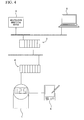
- FIG. 4 is a view illustrating a configuration example of a field control system in accordance with the related art.
- the field control system includes a group of field devices having a field device 1, a multiplexer 2 connected to an upper level of the field device 1, a field controller 3 connected to an upper level of the multiplexer 2, and a manipulation monitoring device 4 and a connection terminal device 5 which are connected to an upper level of the field controller 3.
- the manipulation monitoring device 4 performs an operation and monitoring related to field control of the field device 1 by using communication through a communication path that is via the multiplexer 2 and the field controller 3.
- connection terminal device 5 performs an operation for setting device information or information necessary for communication on the field device 1 through a communication path that is via the multiplexer 2 and the field controller 3.
- the connection terminal device 5 stores a device management database for which data input and data update are necessary corresponding to setting for the field device 1.
- connection terminal device 5 which is a host, performs setting for the field device 1 by performing communication with the field device 1 through the communication path via the field controller 3 and the multiplexer 2.
- Method 1 the setting operation is performed by using the connection terminal device 5.
- the connection terminal device 5 performs setting for the field device 1 and data input or data update to the device management database stored in the connection terminal device 5 simultaneously in parallel.
- the field control uses the communication path between the field device 1 and the manipulation monitoring device. Thereby, the communication speed when performing setting for the field device 1 may be lowered, depending on the number of field devices, performance of the field controller 3 or the like, and thus the setting process may require a long time.
- setting is necessary to specify a communication path for access from the connection terminal device 5 to the field device 1. For example, it is necessary to specify connection ports of the field controller 3 and the multiplexer 2 so that the connection terminal device 5 specifies the communication path to connect to the field device 1. As such, when the scale of the field control system is large, a complicated procedure is necessary.
- a portable terminal device 6 is used to perform setting for the field device 1.
- Method 2 while the portable terminal device 6 is directly connected to the field device 1, input operations to an operation screen and an operation unit in the portable terminal device 6 are performed. Thereby, it is possible to write information to the field device 1.
- Method 2 since the portable terminal device 6 is directly connected to the field device 1, an operation in the field of a plant is necessary. In addition, it is difficult to access the connection terminal device 5 from the portable terminal device 6. As such, data input or data update to the device management database stored in the connection terminal device 5 needs to be performed through an operation on the connection terminal device 5, differently from the setting operation using the portable terminal device 6. For this reason, both an operation by an operator in the field of a plant and an operation by another operator in a control room or an instrument panel room, in which the connection terminal device 5 is installed, are necessary. As such, it is difficult for the operators to cooperate.
- the present invention provides a setting method of a field device and a setting system of a field device that reduce the burden of performing a setting process on the field device.
- a setting system of field devices may include: a first communication path connected to each of the field devices; a terminal device that performs a first setting for each of the field devices through the first communication path; a relay device connected to each of the field devices; and a second communication path formed between each of the field devices and the terminal device via the relay device, the second communication path being different from the first communication path.
- the terminal device may include: a receiving unit that receives an input operation of information; a first setting unit that performs the first setting for each of the field devices by transmitting information necessary for the first setting from the terminal device to each of the field devices through the second communication path in response to the input operation received by the receiving unit; and a second setting unit that performs a second setting for the terminal device, the second setting being necessary with the first setting for each of the field devices in response to the input operation received by the receiving unit.
- the relay device may be a setting terminal device having a function of performing the first setting for each of the field devices connected to the relay device by receiving the input operation in a state in which the relay device is directly connected to each of the field devices.
- the first setting for each of the field devices may set various parameters such as device information and information necessary for communication.
- the terminal device may store a device management database for which data input and data update are needed based on the first setting for each of the field devices. If write and change of parameters are performed on each of the field devices, then update of the device management database may be needed as the second setting for connection terminal device.
- the terminal device may function as a terminal device on which a DTM frame, a DeviceDTM, and a virtual CommDTM operates.
- the relay device may include the DTM frame, a CommDTM, and a virtual DeviceDTM.
- the virtual CommDTM and the virtual DeviceDTM may perform transfer of data by using a communication interface included in each of the terminal device and the relay device.
- the communication interface may be one of Ethernet communication, Bluetooth, a telephone line, a satellite communication device, and a PLC.
- a setting method of field devices that performs setting for each of the field devices through a terminal device, each of the field devices being connected to a first communication path that is used in control data communication may include: forming a second communication path via a relay device between each of the field devices and the terminal device by connecting the relay device to each of the field devices, the second communication path being different from the first communication path; receiving an input operation of information by the terminal device; performing, by the terminal device, a first setting that sets for each of the field devices by transmitting information necessary for the first setting from the terminal device to each of the field devices through the second communication path in response to the input operation received by the terminal device; and performing, by the terminal device, a second setting that sets for the terminal device that is necessary with the first setting for each of the field devices in response to the input operation received by the terminal device.
- the relay device may be a setting terminal device having a function of performing the first setting for each of the field devices connected to the relay device by receiving the input operation in a state in which the relay device is directly connected to each of the field devices.
- the setting method of field devices may further include: performing the control data communication by using the second communication path.
- the setting method of field devices may further include: collecting information stored in each of the field devices by using the second communication path.
- the first setting for each of the field devices may set various parameters such as device information and information necessary for communication.
- the terminal device may store a device management database for which data input and data update are needed based on the first setting for each of the field devices. If write and change of parameters are performed on each of the field devices, then update of the device management database may be needed as the second setting for connection terminal device.
- the terminal device may function as a terminal device on which a DTM frame, a DeviceDTM, and a virtual CommDTM operates.
- the relay device may include the DTM frame, a CommDTM, and a virtual DeviceDTM.
- the virtual CommDTM and the virtual DeviceDTM may perform transfer of data by using a communication interface included in each of the terminal device and the relay device.
- the communication interface may be one of Ethernet communication, Bluetooth, a telephone line, a satellite communication device, and a PLC.
- the setting method of a field device and the setting system of a field device of the preferred embodiment of the present invention information necessary for setting for the field device is transmitted from a terminal device to the field device through the second communication path.
- the terminal device performs setting for the field device
- the terminal device performs setting for the terminal device itself that is necessary along with the setting for the field device.
- a burden of performing the setting process on the field device can be reduced.
- FIG 1 is a block diagram illustrating a configuration example of a field control system that includes a setting system of a field device to which a setting method of a field device is applied in accordance with the first preferred embodiment of the present invention.
- FIG. 1 illustrates only a connection part associated with the field device to be subjected to the setting process, but a plurality of field devices may be connected to the field control system.
- the field control system includes a group of field devices having a field device 1, a multiplexer 2 connected to an upper level of the field device 1, a field controller 3 connected to an upper level of the multiplexer 2, and a manipulation monitoring device 4 and an connection terminal device 5 which are connected to an upper level of the field controller 3.
- the field control system further includes a portable terminal device 6 that is connected to the field device 1, and a communication line 7 formed between the portable terminal device 6 and the connection terminal device 5.
- the connection terminal device 5 includes a receiving unit 51 that receives an input operation of information; a first setting unit 52 that performs setting for the field device 1 by transmitting information necessary for the setting from the connection terminal device 5 to the field device 1 through the communication line 7 in response to the input operation received by the receiving unit 51; and a second setting unit 53 that performs setting for the connection terminal device 5 that is necessary with the setting for each of the field device 1 in response to the input operation received by the receiving unit 51.
- the manipulation monitoring device 4 performs the operation and monitoring related to field control of the field device 1 by using communication through a first communication path that is via the multiplexer 2 and the field controller 3.
- the connection terminal device 5 performs an operation for setting various parameters such as device information and information necessary for communication for the field device 1 through the first communication path that is via the multiplexer 2 and the field controller 3.
- the connection terminal device 5 stores a device management database for which data input and data update are needed based on setting for the field device 1. If write and change of parameters are performed on the field device 1, then update of the device management database is needed as a setting for the connection terminal device 5.
- connection terminal device 5 which is a host, performs setting for the field device 1 by performing communication with the field device 1 through the first communication path via the field controller 3 and the multiplexer 2.
- Method 1 the setting operation is performed by using the connection terminal device 5.
- the connection terminal device 5 performs setting for the field device 1, and data input or data update to the device management database stored in the connection terminal device 5 simultaneously in parallel.
- the field control uses the first communication path between the field device 1 and the manipulation monitoring device. Thereby, the communication speed when performing setting for the field device 1 may be lowered, depending on the number of field devices, performance of the field controller 3 or the like, and thus the setting process may require a long time.
- setting is necessary to specify the first communication path for access from the connection terminal device 5 to the field device 1. For example, it is necessary to specify connection ports of the field controller 3 and the multiplexer 2 so that the connection terminal device 5 specifies the first communication path to connect to the field device 1. As such, when the scale of the field control system is large, a complicated procedure is necessary.
- a portable terminal device 6 is used to perform setting for the field device 1.
- Method 2 while the portable terminal device 6 is directly connected to the field device 1, input operations to an operation screen 61 and an operation unit 62 in the portable terminal device 6 are performed. Thereby, it is possible to write information to the field device 1.
- Method 2 since the portable terminal device 6 is directly connected to the field device 1, an operation in the field of a plant is necessary. In addition, it is difficult to access the connection terminal device 5 from the portable terminal device 6. As such, data input or data update to the device management database stored in the connection terminal device 5 needs to be performed through an operation on the connection terminal device 5, differently from the setting operation using the portable terminal device 6. For this reason, both an operation by an operator in the field of a plant and an operation by another operator in a control room or an instrument panel room, in which the connection terminal device 5 is installed, are necessary. As such, it is difficult for the operators to cooperate.
- the portable terminal device 6 is used as a relay device to perform setting for the field device 1 from the connection terminal device 5.
- FDT/DTM standard advocated by FDTGroup is described as software for performing setting of the field device.
- FIG. 2 is a view illustrating a connection state between the field device 1 and the connection terminal device 5 in accordance with the first preferred embodiment of the present invention.
- the portable terminal device 6 is connected to the field device 1.
- the field device 1 and the connection terminal device 5 are connected by using a second communication path through the portable terminal device 6 and a communication line 7.
- a communication interface is mounted on the portable terminal device 6. The communication interface is used to perform communication between the field device 1 and the connection terminal device 5.
- a first area 81 indicates a software configuration in the connection terminal device 5.
- the first area 81 includes a User Interface (UI), a DeviceDTM, and a unit with a reference numeral "A.”
- a Device Type Manager (DeviceDTM) is drive software of a field device provided based on Field Device Tool (FDT) technology.
- the unit with a reference numeral "A” is a virtual CommDTM.
- the unit with a reference numeral "A” is recognized as a CommDTM, and an operator can perform the setting operation on the field device 1 through a display screen in the connection terminal device 5.
- the CommDTM is drive software for supporting communication with the field device 1.
- a second area 82 indicates a software configuration in the portable terminal device 6.
- the second area 82 includes a unit with a reference numeral "B," a CommDTM, and the field device 1 as a Device.
- the unit with a reference numeral "B” is a virtual DeviceDTM.
- the unit with a reference numeral "B” is recognized as a DeviceDTM, and performs the transfer of data on the CommDTM, calls a parameter from the field device 1 as a Device, and writes the parameter to the field device 1.
- the portable terminal device 6 includes a DTM frame, the CommDTM, and the virtual DeviceDTM.
- the connection terminal device 5 functions as a terminal device on which the DTM frame, the DeviceDTM, and the virtual CommDTM operates.
- a third area 83 indicates a software configuration in the communication line 7.
- the third area 83 includes the virtual CommDTM ("A") and the virtual DeviceDTM ("B").
- the virtual CommDTM ("A") and the virtual DeviceDTM ("B") perform the transfer of data by using the communication interface included in each of the connection terminal device 5 and the portable terminal device 6.
- the communication interface may be one of Ethernet communication, Bluetooth, a telephone line, a satellite communication device, and a PLC.
- connection terminal device 5 when the connection terminal device 5 receives the input operation, the connection terminal device 5 transmits a necessary parameter to the field device 1 through the second communication path via the terminal device 6 and the communication line 7. Thereby, the necessary parameter is written to the field device 1.
- connection terminal device 5 when the connection terminal device 5 receives the input operation, the connection terminal device 5 performs a necessary data input or data update on the device management database stored in the connection terminal device 5.
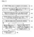
- FIG. 3 is a flow chart illustrating the setting method (Method 3) of the field device in accordance with the first preferred embodiment of the present invention.
- step S1 the portable terminal device 6 is connected to the field device 1.
- step S2 the field device 1 and the connection terminal device 5 are connected by using the second communication path.
- step S3 communication between the field device 1 and the connection terminal device 5 is performed by using the communication interface.
- step S4 an operator performs setting operation on the field device 1 through a display screen in the connection terminal device 5.
- step S5 the connection terminal device 5 receives input operation.
- connection terminal device 5 receives the input operation, then, in step S6, the connection terminal device 5 transmits information to the field device 1 through the second communication path. Thereby, in step S7, the information is written to the field device 1.
- connection terminal device 5 receives the input operation, then, in step S8, the connection terminal device 5 performs data input or data update on device management database stored in the connection terminal device 5.
- the field device 1 is connected to the connection terminal device 5, without using the first communication path (field control communication line) through the field controller 3 and the multiplexer 2.
- the setting process is performed irrespective of situations of the first communication path (field control communication line).
- the first communication path (field control communication line) is not used while the setting process is performed on the field device.
- a negative effect of the setting process for the field device on field control communication can be avoided.
- the setting process can be performed on the field device 1 by only the input operation for the connection terminal device 5, and in parallel the data input and the data update are performed on the device management database stored in the connection terminal device 5. Thereby, it is not necessary to coordinate the operation in the field of a plant with the operation in the control room or the instrument panel room.
- connection terminal device 5 can easily support various communication interfaces. As for change of the communication interface, all you have to do is to replace software for the unit with a reference numeral "A" and the unit with a reference numeral "B" in the third area 83 in FIG. 2 with software corresponding to the communication interface to be used.
- a familiar OS and software can be used by using a general-purpose terminal device as the connection terminal device 5. Thereby, the setting process can be performed without requiring any knowledge of dedicated hardware or dedicated software.
- a kind of supportable communication interface is increased and, for example, the satellite line or the like is available, then access from a remote place to the field device becomes enabled.
- a low-speed line can be used as the second communication path for setting the field device through the portable terminal device 6 and the communication line 7.
- the second communication path for performing the setting process on the field device can temporarily be used as a line for field control communication. That is, the second communication path through the portable terminal device 6 and the communication line 7, together with the first communication path (field control communication line) through the field controller 3 and the multiplexer 2 can be used as the field control communication line. Thereby, a redundancy of field control communication can be achieved.
- the second communication path through the portable terminal device 6 and the communication line 7 can be used to collect data while the field test is performed or the like.
- process data, error information, a self diagnosing result or the like stored in the field device 1 can be collected to the side of the connection terminal device 5 through the second communication path that is via the portable terminal device 6 and the communication line 7.
- the terminal device performs setting for the field device by transmitting information necessary for setting the field device from the terminal device to the field device through the second communication path, and the terminal device performs setting for the terminal device itself necessary with the setting for the field device. Thereby the burden for the setting process can be reduced.
- the present invention can be widely applied to the setting method of a field device, the setting system of a field device or the like that performs setting for each field device, to which a communication line used in control data communication is connected, through the terminal device.
- the term "configured” is used to describe a component, unit or part of a device includes hardware and/or software that is constructed and/or programmed to carry out the desired function.
- unit is used to describe a component, unit or part of a hardware and/or software that is constructed and/or programmed to carry out the desired function.
- Typical examples of the hardware may include, but are not limited to, a device and a circuit.
Landscapes
- Physics & Mathematics (AREA)
- General Physics & Mathematics (AREA)
- Engineering & Computer Science (AREA)
- Automation & Control Theory (AREA)
- Programmable Controllers (AREA)
- Mobile Radio Communication Systems (AREA)
- Radio Relay Systems (AREA)
Abstract
Description
- The present invention relates to a setting method of a field device that is capable of performing setting for each field device, to which a communication line used in control data communication is connected, through a terminal device.
- Priority is claimed on Japanese Patent Application No.
2011-217251, filed September 30, 2011 - All patents, patent applications, patent publications, scientific articles, and the like, which will hereinafter be cited or identified in the present application, will hereby be incorporated by reference in their entirety in order to describe more fully the state of the art to which the present invention pertains.
- When a field device is installed in a plant or when setting for the field device is changed, a setting process for various parameters such as device information and information necessary for communication is performed on the field device via communication.
-
FIG. 4 is a view illustrating a configuration example of a field control system in accordance with the related art. As shown inFIG. 4 , the field control system includes a group of field devices having afield device 1, amultiplexer 2 connected to an upper level of thefield device 1, afield controller 3 connected to an upper level of themultiplexer 2, and amanipulation monitoring device 4 and aconnection terminal device 5 which are connected to an upper level of thefield controller 3. - The
manipulation monitoring device 4 performs an operation and monitoring related to field control of thefield device 1 by using communication through a communication path that is via themultiplexer 2 and thefield controller 3. - The
connection terminal device 5 performs an operation for setting device information or information necessary for communication on thefield device 1 through a communication path that is via themultiplexer 2 and thefield controller 3. Theconnection terminal device 5 stores a device management database for which data input and data update are necessary corresponding to setting for thefield device 1. - Next, an operation procedure when the setting process for the
field device 1 is performed will be described. Two methods will be described below as examples of an operation method. - The
connection terminal device 5, which is a host, performs setting for thefield device 1 by performing communication with thefield device 1 through the communication path via thefield controller 3 and themultiplexer 2. - In
Method 1, the setting operation is performed by using theconnection terminal device 5. Thereby, theconnection terminal device 5 performs setting for thefield device 1 and data input or data update to the device management database stored in theconnection terminal device 5 simultaneously in parallel. - In
Method 1, the field control uses the communication path between thefield device 1 and the manipulation monitoring device. Thereby, the communication speed when performing setting for thefield device 1 may be lowered, depending on the number of field devices, performance of thefield controller 3 or the like, and thus the setting process may require a long time. - When setting for the
field device 1 is performed, setting is necessary to specify a communication path for access from theconnection terminal device 5 to thefield device 1. For example, it is necessary to specify connection ports of thefield controller 3 and themultiplexer 2 so that theconnection terminal device 5 specifies the communication path to connect to thefield device 1. As such, when the scale of the field control system is large, a complicated procedure is necessary. - A
portable terminal device 6 is used to perform setting for thefield device 1. InMethod 2, while theportable terminal device 6 is directly connected to thefield device 1, input operations to an operation screen and an operation unit in theportable terminal device 6 are performed. Thereby, it is possible to write information to thefield device 1. - In
Method 2, since theportable terminal device 6 is directly connected to thefield device 1, an operation in the field of a plant is necessary. In addition, it is difficult to access theconnection terminal device 5 from theportable terminal device 6. As such, data input or data update to the device management database stored in theconnection terminal device 5 needs to be performed through an operation on theconnection terminal device 5, differently from the setting operation using theportable terminal device 6. For this reason, both an operation by an operator in the field of a plant and an operation by another operator in a control room or an instrument panel room, in which theconnection terminal device 5 is installed, are necessary. As such, it is difficult for the operators to cooperate. - The present invention provides a setting method of a field device and a setting system of a field device that reduce the burden of performing a setting process on the field device.
- A setting system of field devices may include: a first communication path connected to each of the field devices; a terminal device that performs a first setting for each of the field devices through the first communication path; a relay device connected to each of the field devices; and a second communication path formed between each of the field devices and the terminal device via the relay device, the second communication path being different from the first communication path. The terminal device may include: a receiving unit that receives an input operation of information; a first setting unit that performs the first setting for each of the field devices by transmitting information necessary for the first setting from the terminal device to each of the field devices through the second communication path in response to the input operation received by the receiving unit; and a second setting unit that performs a second setting for the terminal device, the second setting being necessary with the first setting for each of the field devices in response to the input operation received by the receiving unit.
- The relay device may be a setting terminal device having a function of performing the first setting for each of the field devices connected to the relay device by receiving the input operation in a state in which the relay device is directly connected to each of the field devices.
- The first setting for each of the field devices may set various parameters such as device information and information necessary for communication.
- The terminal device may store a device management database for which data input and data update are needed based on the first setting for each of the field devices. If write and change of parameters are performed on each of the field devices, then update of the device management database may be needed as the second setting for connection terminal device.
- The terminal device may function as a terminal device on which a DTM frame, a DeviceDTM, and a virtual CommDTM operates. The relay device may include the DTM frame, a CommDTM, and a virtual DeviceDTM.
- The virtual CommDTM and the virtual DeviceDTM may perform transfer of data by using a communication interface included in each of the terminal device and the relay device.
- The communication interface may be one of Ethernet communication, Bluetooth, a telephone line, a satellite communication device, and a PLC.
- A setting method of field devices that performs setting for each of the field devices through a terminal device, each of the field devices being connected to a first communication path that is used in control data communication, may include: forming a second communication path via a relay device between each of the field devices and the terminal device by connecting the relay device to each of the field devices, the second communication path being different from the first communication path; receiving an input operation of information by the terminal device; performing, by the terminal device, a first setting that sets for each of the field devices by transmitting information necessary for the first setting from the terminal device to each of the field devices through the second communication path in response to the input operation received by the terminal device; and performing, by the terminal device, a second setting that sets for the terminal device that is necessary with the first setting for each of the field devices in response to the input operation received by the terminal device.
- The relay device may be a setting terminal device having a function of performing the first setting for each of the field devices connected to the relay device by receiving the input operation in a state in which the relay device is directly connected to each of the field devices.
- The setting method of field devices may further include: performing the control data communication by using the second communication path.
- The setting method of field devices may further include: collecting information stored in each of the field devices by using the second communication path.
- The first setting for each of the field devices may set various parameters such as device information and information necessary for communication.
- The terminal device may store a device management database for which data input and data update are needed based on the first setting for each of the field devices. If write and change of parameters are performed on each of the field devices, then update of the device management database may be needed as the second setting for connection terminal device.
- The terminal device may function as a terminal device on which a DTM frame, a DeviceDTM, and a virtual CommDTM operates. The relay device may include the DTM frame, a CommDTM, and a virtual DeviceDTM.
- The virtual CommDTM and the virtual DeviceDTM may perform transfer of data by using a communication interface included in each of the terminal device and the relay device.
- The communication interface may be one of Ethernet communication, Bluetooth, a telephone line, a satellite communication device, and a PLC.
- According to the setting method of a field device and the setting system of a field device of the preferred embodiment of the present invention, information necessary for setting for the field device is transmitted from a terminal device to the field device through the second communication path. Thereby, while the terminal device performs setting for the field device, the terminal device performs setting for the terminal device itself that is necessary along with the setting for the field device. As such, a burden of performing the setting process on the field device can be reduced.
- The above features and advantages of the present invention will be more apparent from the following description of certain preferred embodiments taken in conjunction with the accompanying drawings, in which:
-
FIG. 1 is a block diagram illustrating a configuration example of a field control system that includes a setting system of a field device to which a setting method of a field device is applied in accordance with a first preferred embodiment of the present invention; -
FIG. 2 is a view illustrating a connection state between the field device and a connection terminal device in accordance with the first preferred embodiment of the present invention; -
FIG. 3 is a flow chart illustrating the setting method (Method 3) of the field device in accordance with the first preferred embodiment of the present invention; and -
FIG. 4 is a view illustrating a configuration example of a field control system in accordance with the related art. - The present invention will be now described herein with reference to illustrative preferred embodiments. Those skilled in the art will recognize that many alternative preferred embodiments can be accomplished using the teaching of the present invention and that the present invention is not limited to the preferred embodiments illustrated herein for explanatory purposes.
- A first preferred embodiment of the present invention will be described.
FIG 1 is a block diagram illustrating a configuration example of a field control system that includes a setting system of a field device to which a setting method of a field device is applied in accordance with the first preferred embodiment of the present invention.FIG. 1 illustrates only a connection part associated with the field device to be subjected to the setting process, but a plurality of field devices may be connected to the field control system. - As illustrated in
FIG. 1 , the field control system includes a group of field devices having afield device 1, amultiplexer 2 connected to an upper level of thefield device 1, afield controller 3 connected to an upper level of themultiplexer 2, and amanipulation monitoring device 4 and anconnection terminal device 5 which are connected to an upper level of thefield controller 3. - In the preferred embodiment of the present invention, the field control system further includes a portable
terminal device 6 that is connected to thefield device 1, and acommunication line 7 formed between the portableterminal device 6 and theconnection terminal device 5. Theconnection terminal device 5 includes a receivingunit 51 that receives an input operation of information; afirst setting unit 52 that performs setting for thefield device 1 by transmitting information necessary for the setting from theconnection terminal device 5 to thefield device 1 through thecommunication line 7 in response to the input operation received by the receivingunit 51; and asecond setting unit 53 that performs setting for theconnection terminal device 5 that is necessary with the setting for each of thefield device 1 in response to the input operation received by the receivingunit 51. - The
manipulation monitoring device 4 performs the operation and monitoring related to field control of thefield device 1 by using communication through a first communication path that is via themultiplexer 2 and thefield controller 3. - The
connection terminal device 5 performs an operation for setting various parameters such as device information and information necessary for communication for thefield device 1 through the first communication path that is via themultiplexer 2 and thefield controller 3. Theconnection terminal device 5 stores a device management database for which data input and data update are needed based on setting for thefield device 1. If write and change of parameters are performed on thefield device 1, then update of the device management database is needed as a setting for theconnection terminal device 5. - Next, an operation procedure when the setting process for the
field device 1 is performed will be described. Three methods will be described below as examples of an operation method. The present invention is characterized inMethod 3. - The
connection terminal device 5, which is a host, performs setting for thefield device 1 by performing communication with thefield device 1 through the first communication path via thefield controller 3 and themultiplexer 2. - In
Method 1, the setting operation is performed by using theconnection terminal device 5. Thereby, theconnection terminal device 5 performs setting for thefield device 1, and data input or data update to the device management database stored in theconnection terminal device 5 simultaneously in parallel. - In
Method 1, the field control uses the first communication path between thefield device 1 and the manipulation monitoring device. Thereby, the communication speed when performing setting for thefield device 1 may be lowered, depending on the number of field devices, performance of thefield controller 3 or the like, and thus the setting process may require a long time. - When setting for the
field device 1 is performed, setting is necessary to specify the first communication path for access from theconnection terminal device 5 to thefield device 1. For example, it is necessary to specify connection ports of thefield controller 3 and themultiplexer 2 so that theconnection terminal device 5 specifies the first communication path to connect to thefield device 1. As such, when the scale of the field control system is large, a complicated procedure is necessary. - A portable
terminal device 6 is used to perform setting for thefield device 1. InMethod 2, while the portableterminal device 6 is directly connected to thefield device 1, input operations to anoperation screen 61 and anoperation unit 62 in the portableterminal device 6 are performed. Thereby, it is possible to write information to thefield device 1. - In
Method 2, since the portableterminal device 6 is directly connected to thefield device 1, an operation in the field of a plant is necessary. In addition, it is difficult to access theconnection terminal device 5 from the portableterminal device 6. As such, data input or data update to the device management database stored in theconnection terminal device 5 needs to be performed through an operation on theconnection terminal device 5, differently from the setting operation using the portableterminal device 6. For this reason, both an operation by an operator in the field of a plant and an operation by another operator in a control room or an instrument panel room, in which theconnection terminal device 5 is installed, are necessary. As such, it is difficult for the operators to cooperate. - In
Method 3, the portableterminal device 6 is used as a relay device to perform setting for thefield device 1 from theconnection terminal device 5. In the first preferred embodiment of the present invention, an example using FDT/DTM standard advocated by FDTGroup is described as software for performing setting of the field device. -
FIG. 2 is a view illustrating a connection state between thefield device 1 and theconnection terminal device 5 in accordance with the first preferred embodiment of the present invention. - As shown in
FIGS. 1 and2 , the portableterminal device 6 is connected to thefield device 1. Thereby, thefield device 1 and theconnection terminal device 5 are connected by using a second communication path through the portableterminal device 6 and acommunication line 7. A communication interface is mounted on the portableterminal device 6. The communication interface is used to perform communication between thefield device 1 and theconnection terminal device 5. - In
FIG 2 , afirst area 81 indicates a software configuration in theconnection terminal device 5. Thefirst area 81 includes a User Interface (UI), a DeviceDTM, and a unit with a reference numeral "A." A Device Type Manager (DeviceDTM) is drive software of a field device provided based on Field Device Tool (FDT) technology. The unit with a reference numeral "A" is a virtual CommDTM. The unit with a reference numeral "A" is recognized as a CommDTM, and an operator can perform the setting operation on thefield device 1 through a display screen in theconnection terminal device 5. The CommDTM is drive software for supporting communication with thefield device 1. - In
FIG 2 , asecond area 82 indicates a software configuration in the portableterminal device 6. Thesecond area 82 includes a unit with a reference numeral "B," a CommDTM, and thefield device 1 as a Device. The unit with a reference numeral "B" is a virtual DeviceDTM. The unit with a reference numeral "B" is recognized as a DeviceDTM, and performs the transfer of data on the CommDTM, calls a parameter from thefield device 1 as a Device, and writes the parameter to thefield device 1. - The portable
terminal device 6 includes a DTM frame, the CommDTM, and the virtual DeviceDTM. Theconnection terminal device 5 functions as a terminal device on which the DTM frame, the DeviceDTM, and the virtual CommDTM operates. - A
third area 83 indicates a software configuration in thecommunication line 7. Thethird area 83 includes the virtual CommDTM ("A") and the virtual DeviceDTM ("B"). In the third area, the virtual CommDTM ("A") and the virtual DeviceDTM ("B") perform the transfer of data by using the communication interface included in each of theconnection terminal device 5 and the portableterminal device 6. The communication interface may be one of Ethernet communication, Bluetooth, a telephone line, a satellite communication device, and a PLC. - Using the above configuration, when the
connection terminal device 5 receives the input operation, theconnection terminal device 5 transmits a necessary parameter to thefield device 1 through the second communication path via theterminal device 6 and thecommunication line 7. Thereby, the necessary parameter is written to thefield device 1. - Also, when the
connection terminal device 5 receives the input operation, theconnection terminal device 5 performs a necessary data input or data update on the device management database stored in theconnection terminal device 5. -
FIG. 3 is a flow chart illustrating the setting method (Method 3) of the field device in accordance with the first preferred embodiment of the present invention. - In step S1, the portable
terminal device 6 is connected to thefield device 1. Thereby, in step S2, thefield device 1 and theconnection terminal device 5 are connected by using the second communication path. Then, in step S3, communication between thefield device 1 and theconnection terminal device 5 is performed by using the communication interface. - Then, in step S4, an operator performs setting operation on the
field device 1 through a display screen in theconnection terminal device 5. In step S5, theconnection terminal device 5 receives input operation. - If the
connection terminal device 5 receives the input operation, then, in step S6, theconnection terminal device 5 transmits information to thefield device 1 through the second communication path. Thereby, in step S7, the information is written to thefield device 1. - In parallel, if the
connection terminal device 5 receives the input operation, then, in step S8, theconnection terminal device 5 performs data input or data update on device management database stored in theconnection terminal device 5. - In this manner, according to
Method 3, thefield device 1 is connected to theconnection terminal device 5, without using the first communication path (field control communication line) through thefield controller 3 and themultiplexer 2. As such, the setting process is performed irrespective of situations of the first communication path (field control communication line). The first communication path (field control communication line) is not used while the setting process is performed on the field device. Thus, a negative effect of the setting process for the field device on field control communication can be avoided. - The setting process can be performed on the
field device 1 by only the input operation for theconnection terminal device 5, and in parallel the data input and the data update are performed on the device management database stored in theconnection terminal device 5. Thereby, it is not necessary to coordinate the operation in the field of a plant with the operation in the control room or the instrument panel room. - In addition, a general-purpose terminal device can be used as the
connection terminal device 5. Thereby, theconnection terminal device 5 can easily support various communication interfaces. As for change of the communication interface, all you have to do is to replace software for the unit with a reference numeral "A" and the unit with a reference numeral "B" in thethird area 83 inFIG. 2 with software corresponding to the communication interface to be used. A familiar OS and software can be used by using a general-purpose terminal device as theconnection terminal device 5. Thereby, the setting process can be performed without requiring any knowledge of dedicated hardware or dedicated software. In addition, if a kind of supportable communication interface is increased and, for example, the satellite line or the like is available, then access from a remote place to the field device becomes enabled. - Since the amount of data and parameters in the field device to be subjected to the setting process are relatively small, the amount of communication while setting the field device can be suppressed. Accordingly, a low-speed line can be used as the second communication path for setting the field device through the portable
terminal device 6 and thecommunication line 7. - By connecting the portable
terminal device 6 to thefield device 1, the second communication path for performing the setting process on the field device can temporarily be used as a line for field control communication. That is, the second communication path through the portableterminal device 6 and thecommunication line 7, together with the first communication path (field control communication line) through thefield controller 3 and themultiplexer 2 can be used as the field control communication line. Thereby, a redundancy of field control communication can be achieved. - The second communication path through the portable
terminal device 6 and thecommunication line 7 can be used to collect data while the field test is performed or the like. For example, process data, error information, a self diagnosing result or the like stored in thefield device 1 can be collected to the side of theconnection terminal device 5 through the second communication path that is via the portableterminal device 6 and thecommunication line 7. - As described above, according to the setting method of a field device and the setting system of a field device of the present invention, the terminal device performs setting for the field device by transmitting information necessary for setting the field device from the terminal device to the field device through the second communication path, and the terminal device performs setting for the terminal device itself necessary with the setting for the field device. Thereby the burden for the setting process can be reduced.
- The present invention can be widely applied to the setting method of a field device, the setting system of a field device or the like that performs setting for each field device, to which a communication line used in control data communication is connected, through the terminal device.
- As used herein, the following directional terms "forward, rearward, above, downward, right, left, vertical, horizontal, below, transverse, row and column" as well as any other similar directional terms refer to those directions of an apparatus equipped with the present invention. Accordingly, these terms, as utilized to describe the present invention should be interpreted relative to an apparatus equipped with the present invention.
- The term "configured" is used to describe a component, unit or part of a device includes hardware and/or software that is constructed and/or programmed to carry out the desired function.
- Moreover, terms that are expressed as "means-plus function" in the claims should include any structure that can be utilized to carry out the function of that part of the present invention.
- The term "unit" is used to describe a component, unit or part of a hardware and/or software that is constructed and/or programmed to carry out the desired function. Typical examples of the hardware may include, but are not limited to, a device and a circuit.
- While preferred embodiments of the present invention have been described and illustrated above, it should be understood that these are examples of the present invention and are not to be considered as limiting. Additions, omissions, substitutions, and other modifications can be made without departing from the scope of the present invention. Accordingly, the present invention is not to be considered as being limited by the foregoing description, and is only limited by the scope of the claims.
Claims (15)
- A setting system of field devices comprising:a first communication path connected to each of the field devices;a terminal device that performs a first setting for each of the field devices through the first communication path;a relay device connected to each of the field devices; anda second communication path formed between each of the field devices and the terminal device via the relay device, the second communication path being different from the first communication path,wherein the terminal device comprising:a receiving unit that receives an input operation of information;a first setting unit that performs the first setting for each of the field devices by transmitting information necessary for the first setting from the terminal device to each of the field devices through the second communication path in response to the input operation received by the receiving unit; anda second setting unit that performs a second setting for the terminal device, the second setting being necessary with the first setting for each of the field devices in response to the input operation received by the receiving unit.
- The setting system of field devices according to claim 1, wherein
the relay device is a setting terminal device having a function of performing the first setting for each of the field devices connected to the relay device by receiving the input operation in a state in which the relay device is directly connected to each of the field devices. - The setting system of field devices according to claim 1, wherein
the first setting for each of the field devices sets various parameters such as device information and information necessary for communication. - The setting system of field devices according to claim 1, wherein
the terminal device stores a device management database for which data input and data update are needed based on the first setting for each of the field devices,
if write and change of parameters are performed on each of the field devices, then update of the device management database is needed as the second setting for connection terminal device. - The setting system of field devices according to claim 1, wherein
the terminal device functions as a terminal device on which a DTM frame, a DeviceDTM, and a virtual CommDTM operates, and
the relay device includes the DTM frame, a CommDTM, and a virtual DeviceDTM. - The setting system of field devices according to claim 5, wherein
the virtual CommDTM and the virtual DeviceDTM perform transfer of data by using a communication interface included in each of the terminal device and the relay device. - The setting system of field devices according to claim 6, wherein
the communication interface is one of Ethernet communication, Bluetooth, a telephone line, a satellite communication device, and a PLC. - A setting method of field devices that performs setting for each of the field devices through a terminal device, each of the field devices being connected to a first communication path that is used in control data communication, the setting method comprising:forming a second communication path via a relay device between each of the field devices and the terminal device by connecting the relay device to each of the field devices, the second communication path being different from the first communication path;receiving an input operation of information by the terminal device;performing, by the terminal device, a first setting that sets for each of the field devices by transmitting information necessary for the first setting from the terminal device to each of the field devices through the second communication path in response to the input operation received by the terminal device; andperforming, by the terminal device, a second setting that sets for the terminal device that is necessary with the first setting for each of the field devices in response to the input operation received by the terminal device.
- The setting method of field devices according to claim 8, wherein
the relay device is a setting terminal device having a function of performing the first setting for each of the field devices connected to the relay device by receiving the input operation in a state in which the relay device is directly connected to each of the field devices. - The setting method of field devices according to claim 8, further comprising:performing the control data communication by using the second communication path.
- The setting method of field devices according to claim 8, further comprising:collecting information stored in each of the field devices by using the second communication path.
- The setting method of field devices according to claim 8, wherein
the first setting for each of the field devices sets various parameters such as device information and information necessary for communication. - The setting method of field devices according to claim 8, wherein
the terminal device stores a device management database for which data input and data update are needed based on the first setting for each of the field devices,
if write and change of parameters are performed on each of the field devices, then update of the device management database is needed as the second setting for connection terminal device. - The setting method of field devices according to claim 8, wherein
the terminal device functions as a terminal device on which a DTM frame, a DeviceDTM, and a virtual CommDTM operates, and
the relay device includes the DTM frame, a CommDTM, and a virtual DeviceDTM. - The setting method of field devices according to claim 14, wherein
the virtual CommDTM and the virtual DeviceDTM perform transfer of data by using a communication interface included in each of the terminal device and the relay device.
Applications Claiming Priority (1)
| Application Number | Priority Date | Filing Date | Title |
|---|---|---|---|
| JP2011217251A JP5483211B2 (en) | 2011-09-30 | 2011-09-30 | Field device setting method and field device setting system |
Publications (3)
| Publication Number | Publication Date |
|---|---|
| EP2575116A2 true EP2575116A2 (en) | 2013-04-03 |
| EP2575116A3 EP2575116A3 (en) | 2016-11-16 |
| EP2575116B1 EP2575116B1 (en) | 2021-11-03 |
Family
ID=47221927
Family Applications (1)
| Application Number | Title | Priority Date | Filing Date |
|---|---|---|---|
| EP12184828.7A Active EP2575116B1 (en) | 2011-09-30 | 2012-09-18 | Setting method of field device and setting system of field device |
Country Status (4)
| Country | Link |
|---|---|
| US (1) | US8953493B2 (en) |
| EP (1) | EP2575116B1 (en) |
| JP (1) | JP5483211B2 (en) |
| CN (1) | CN103034183B (en) |
Cited By (2)
| Publication number | Priority date | Publication date | Assignee | Title |
|---|---|---|---|---|
| EP2952986A1 (en) * | 2014-06-04 | 2015-12-09 | Yokogawa Electric Corporation | Field device management system |
| EP4293439A1 (en) * | 2022-06-13 | 2023-12-20 | Abb Schweiz Ag | Synchronizing field device parameters between an asset management system and field devices |
Families Citing this family (6)
| Publication number | Priority date | Publication date | Assignee | Title |
|---|---|---|---|---|
| US20140358251A1 (en) * | 2013-05-31 | 2014-12-04 | Ge Intelligent Platforms, Inc. | Incorporating fdt/dtm technology into a system-level configuration application for integrated device configuration management |
| US20140359458A1 (en) * | 2013-05-31 | 2014-12-04 | Ge Intelligent Platforms, Inc. | Providing a hybrid fieldbus device management application |
| JP5954342B2 (en) | 2014-02-06 | 2016-07-20 | 横河電機株式会社 | Device setting device, device setting program, storage medium, and information sharing method among a plurality of device setting devices |
| JP6459991B2 (en) | 2016-01-21 | 2019-01-30 | オムロン株式会社 | Sensor, sensor system, and measurement method |
| DE102016124168A1 (en) * | 2016-12-13 | 2018-06-14 | Endress+Hauser Conducta Gmbh+Co. Kg | Method for operating a specific field device via a mobile operating device |
| JP6658494B2 (en) * | 2016-12-20 | 2020-03-04 | 横河電機株式会社 | Work support device, work support system, work support method, program, and recording medium |
Family Cites Families (21)
| Publication number | Priority date | Publication date | Assignee | Title |
|---|---|---|---|---|
| CA2203561C (en) * | 1994-10-24 | 2004-09-21 | Thomas Andrew Boyd | Apparatus for providing access to field devices in a distributed control system |
| US6094600A (en) * | 1996-02-06 | 2000-07-25 | Fisher-Rosemount Systems, Inc. | System and method for managing a transaction database of records of changes to field device configurations |
| JP2000183903A (en) * | 1998-12-16 | 2000-06-30 | Fuji Electric Co Ltd | Fieldbus system setting device |
| US7640007B2 (en) * | 1999-02-12 | 2009-12-29 | Fisher-Rosemount Systems, Inc. | Wireless handheld communicator in a process control environment |
| FI111760B (en) * | 1999-04-16 | 2003-09-15 | Metso Automation Oy | Wireless control of a field device in an industrial process |
| US6959356B2 (en) * | 2001-07-30 | 2005-10-25 | Fisher-Rosemount Systems, Inc. | Multi-protocol field device and communication method |
| JP4139758B2 (en) * | 2003-09-29 | 2008-08-27 | 関西電力株式会社 | Path setting method and network, relay station, and master station that employ the path setting method |
| US8160574B1 (en) * | 2005-06-17 | 2012-04-17 | Fisher-Rosemount Systems, Inc. | Wireless architecture utilizing geo-referencing |
| JP4497058B2 (en) * | 2005-08-24 | 2010-07-07 | 横河電機株式会社 | Plant monitoring system |
| JP4797533B2 (en) * | 2005-09-16 | 2011-10-19 | 横河電機株式会社 | Control system and control system parameter setting method |
| US20070067512A1 (en) * | 2005-09-19 | 2007-03-22 | Smar Research Corporation | Method, system and software arrangement for processing a device support file for a field device |
| JP4710548B2 (en) * | 2005-10-27 | 2011-06-29 | 横河電機株式会社 | Field device management device |
| DE102005063162A1 (en) * | 2005-12-30 | 2007-10-31 | Codewrights Gmbh | Method for testing device descriptions for field devices of automation technology |
| JP2008310725A (en) * | 2007-06-18 | 2008-12-25 | Yokogawa Electric Corp | Field device system and system construction method |
| DE102008010864A1 (en) * | 2008-02-25 | 2009-08-27 | Endress + Hauser Process Solutions Ag | Method for operating a field device |
| JP2009284183A (en) * | 2008-05-22 | 2009-12-03 | Yokogawa Electric Corp | Network system and device setting method in network system |
| US8046519B2 (en) * | 2008-10-20 | 2011-10-25 | Daniel Measurement And Control, Inc. | Coupling a specialty system, such as a metering system, to multiple control systems |
| BRPI0922747A2 (en) * | 2008-12-05 | 2017-07-11 | Fisher Controls Int Llc | HANDHELD COMMUNICATOR, METHOD FOR INTERACTING WITH AN ENTITY IN A PROCESS CONTROL SYSTEM, AND, PROCESS CONTROL SYSTEM |
| JP2010258865A (en) * | 2009-04-27 | 2010-11-11 | Yokogawa Electric Corp | Field equipment |
| DE102010016283B4 (en) * | 2010-03-31 | 2011-12-15 | Schneider Electric Automation Gmbh | Method for transmitting data via a CANopen bus and use of the method for configuring and / or parameterizing field devices via the CANopen bus |
| DE102010062266A1 (en) * | 2010-12-01 | 2012-06-21 | Codewrights Gmbh | Method for implementing at least one additional function of a field device in automation technology |
-
2011
- 2011-09-30 JP JP2011217251A patent/JP5483211B2/en not_active Expired - Fee Related
-
2012
- 2012-09-14 US US13/618,775 patent/US8953493B2/en active Active
- 2012-09-18 EP EP12184828.7A patent/EP2575116B1/en active Active
- 2012-09-27 CN CN201210369493.7A patent/CN103034183B/en active Active
Non-Patent Citations (1)
| Title |
|---|
| None |
Cited By (3)
| Publication number | Priority date | Publication date | Assignee | Title |
|---|---|---|---|---|
| EP2952986A1 (en) * | 2014-06-04 | 2015-12-09 | Yokogawa Electric Corporation | Field device management system |
| US10409268B2 (en) | 2014-06-04 | 2019-09-10 | Yokogawa Electric Corporation | Field device management system |
| EP4293439A1 (en) * | 2022-06-13 | 2023-12-20 | Abb Schweiz Ag | Synchronizing field device parameters between an asset management system and field devices |
Also Published As
| Publication number | Publication date |
|---|---|
| US8953493B2 (en) | 2015-02-10 |
| US20130083694A1 (en) | 2013-04-04 |
| JP2013077197A (en) | 2013-04-25 |
| EP2575116A3 (en) | 2016-11-16 |
| CN103034183B (en) | 2016-03-09 |
| CN103034183A (en) | 2013-04-10 |
| EP2575116B1 (en) | 2021-11-03 |
| JP5483211B2 (en) | 2014-05-07 |
Similar Documents
| Publication | Publication Date | Title |
|---|---|---|
| US8953493B2 (en) | Setting method of field device and setting system of field device | |
| JP5000888B2 (en) | Communication method and communication system | |
| CN103226454B (en) | A kind of method and system realizing multihead display | |
| US20130131833A1 (en) | Method, computer program, computer-readable medium and processing unit for controlling field devices | |
| CN103905984A (en) | Remote monitoring method for agricultural machinery | |
| CN105955690A (en) | Multi-screen switching device and method of computer | |
| EP2551735B1 (en) | Fieldbus adapter and method of using fieldbus adapter | |
| US20140207260A1 (en) | Data creating device and method | |
| US20140344428A1 (en) | System architecture support tool | |
| EP3416004A1 (en) | Device management apparatus, device management method, device management program, and non-transitory computer readable storage medium | |
| CN205219137U (en) | Multi -axis motion control of bus type robot ware | |
| CN104950880A (en) | Industrial control equipment debugging system and method | |
| JP5869992B2 (en) | Transfer program generator | |
| CN114912071B (en) | Performance evaluation method, device and system for man-machine interaction | |
| EP4189500B1 (en) | Method for extending the operating functionality of a field device in the field of automation technology from one operating device to at least one other operating device | |
| US20170255340A1 (en) | Information processing apparatus, and control method and control program thereof | |
| CN103558923A (en) | Electronic system and data input method thereof | |
| JP6895208B2 (en) | Plant controller | |
| CN113676763A (en) | Low-delay video transmission method, device and equipment with adaptive display angle and storage medium | |
| CN109669422B (en) | Real-time data acquisition system | |
| CN110824963A (en) | Control device in multimedia equipment cluster | |
| KR20130130439A (en) | Apparatus and method for monitoring of hmi | |
| JP2014092837A (en) | Supervisory control engineering device | |
| JP7114007B1 (en) | Data providing program, data providing device, programmable display system, programmable display, and data providing method | |
| JP4937286B2 (en) | DIGITAL CONTROL SYSTEM, DIGITAL CONTROL DEVICE, AND DIGITAL CONTROL SYSTEM TRANSMISSION TEST METHOD |
Legal Events
| Date | Code | Title | Description |
|---|---|---|---|
| PUAI | Public reference made under article 153(3) epc to a published international application that has entered the european phase |
Free format text: ORIGINAL CODE: 0009012 |
|
| AK | Designated contracting states |
Kind code of ref document: A2 Designated state(s): AL AT BE BG CH CY CZ DE DK EE ES FI FR GB GR HR HU IE IS IT LI LT LU LV MC MK MT NL NO PL PT RO RS SE SI SK SM TR |
|
| AX | Request for extension of the european patent |
Extension state: BA ME |
|
| PUAL | Search report despatched |
Free format text: ORIGINAL CODE: 0009013 |
|
| AK | Designated contracting states |
Kind code of ref document: A3 Designated state(s): AL AT BE BG CH CY CZ DE DK EE ES FI FR GB GR HR HU IE IS IT LI LT LU LV MC MK MT NL NO PL PT RO RS SE SI SK SM TR |
|
| AX | Request for extension of the european patent |
Extension state: BA ME |
|
| RIC1 | Information provided on ipc code assigned before grant |
Ipc: G05B 19/042 20060101ALI20161010BHEP Ipc: G08C 19/30 20060101AFI20161010BHEP |
|
| STAA | Information on the status of an ep patent application or granted ep patent |
Free format text: STATUS: REQUEST FOR EXAMINATION WAS MADE |
|
| 17P | Request for examination filed |
Effective date: 20170516 |
|
| RBV | Designated contracting states (corrected) |
Designated state(s): AL AT BE BG CH CY CZ DE DK EE ES FI FR GB GR HR HU IE IS IT LI LT LU LV MC MK MT NL NO PL PT RO RS SE SI SK SM TR |
|
| STAA | Information on the status of an ep patent application or granted ep patent |
Free format text: STATUS: EXAMINATION IS IN PROGRESS |
|
| 17Q | First examination report despatched |
Effective date: 20180618 |
|
| GRAP | Despatch of communication of intention to grant a patent |
Free format text: ORIGINAL CODE: EPIDOSNIGR1 |
|
| STAA | Information on the status of an ep patent application or granted ep patent |
Free format text: STATUS: GRANT OF PATENT IS INTENDED |
|
| INTG | Intention to grant announced |
Effective date: 20210514 |
|
| GRAS | Grant fee paid |
Free format text: ORIGINAL CODE: EPIDOSNIGR3 |
|
| GRAA | (expected) grant |
Free format text: ORIGINAL CODE: 0009210 |
|
| STAA | Information on the status of an ep patent application or granted ep patent |
Free format text: STATUS: THE PATENT HAS BEEN GRANTED |
|
| AK | Designated contracting states |
Kind code of ref document: B1 Designated state(s): AL AT BE BG CH CY CZ DE DK EE ES FI FR GB GR HR HU IE IS IT LI LT LU LV MC MK MT NL NO PL PT RO RS SE SI SK SM TR |
|
| REG | Reference to a national code |
Ref country code: GB Ref legal event code: FG4D |
|
| REG | Reference to a national code |
Ref country code: AT Ref legal event code: REF Ref document number: 1444681 Country of ref document: AT Kind code of ref document: T Effective date: 20211115 Ref country code: CH Ref legal event code: EP |
|
| REG | Reference to a national code |
Ref country code: IE Ref legal event code: FG4D |
|
| REG | Reference to a national code |
Ref country code: DE Ref legal event code: R096 Ref document number: 602012077065 Country of ref document: DE |
|
| REG | Reference to a national code |
Ref country code: LT Ref legal event code: MG9D |
|
| REG | Reference to a national code |
Ref country code: NL Ref legal event code: MP Effective date: 20211103 |
|
| REG | Reference to a national code |
Ref country code: AT Ref legal event code: MK05 Ref document number: 1444681 Country of ref document: AT Kind code of ref document: T Effective date: 20211103 |
|
| PG25 | Lapsed in a contracting state [announced via postgrant information from national office to epo] |
Ref country code: RS Free format text: LAPSE BECAUSE OF FAILURE TO SUBMIT A TRANSLATION OF THE DESCRIPTION OR TO PAY THE FEE WITHIN THE PRESCRIBED TIME-LIMIT Effective date: 20211103 Ref country code: LT Free format text: LAPSE BECAUSE OF FAILURE TO SUBMIT A TRANSLATION OF THE DESCRIPTION OR TO PAY THE FEE WITHIN THE PRESCRIBED TIME-LIMIT Effective date: 20211103 Ref country code: FI Free format text: LAPSE BECAUSE OF FAILURE TO SUBMIT A TRANSLATION OF THE DESCRIPTION OR TO PAY THE FEE WITHIN THE PRESCRIBED TIME-LIMIT Effective date: 20211103 Ref country code: BG Free format text: LAPSE BECAUSE OF FAILURE TO SUBMIT A TRANSLATION OF THE DESCRIPTION OR TO PAY THE FEE WITHIN THE PRESCRIBED TIME-LIMIT Effective date: 20220203 Ref country code: AT Free format text: LAPSE BECAUSE OF FAILURE TO SUBMIT A TRANSLATION OF THE DESCRIPTION OR TO PAY THE FEE WITHIN THE PRESCRIBED TIME-LIMIT Effective date: 20211103 |
|
| PG25 | Lapsed in a contracting state [announced via postgrant information from national office to epo] |
Ref country code: IS Free format text: LAPSE BECAUSE OF FAILURE TO SUBMIT A TRANSLATION OF THE DESCRIPTION OR TO PAY THE FEE WITHIN THE PRESCRIBED TIME-LIMIT Effective date: 20220303 Ref country code: SE Free format text: LAPSE BECAUSE OF FAILURE TO SUBMIT A TRANSLATION OF THE DESCRIPTION OR TO PAY THE FEE WITHIN THE PRESCRIBED TIME-LIMIT Effective date: 20211103 Ref country code: PT Free format text: LAPSE BECAUSE OF FAILURE TO SUBMIT A TRANSLATION OF THE DESCRIPTION OR TO PAY THE FEE WITHIN THE PRESCRIBED TIME-LIMIT Effective date: 20220303 Ref country code: PL Free format text: LAPSE BECAUSE OF FAILURE TO SUBMIT A TRANSLATION OF THE DESCRIPTION OR TO PAY THE FEE WITHIN THE PRESCRIBED TIME-LIMIT Effective date: 20211103 Ref country code: NO Free format text: LAPSE BECAUSE OF FAILURE TO SUBMIT A TRANSLATION OF THE DESCRIPTION OR TO PAY THE FEE WITHIN THE PRESCRIBED TIME-LIMIT Effective date: 20220203 Ref country code: NL Free format text: LAPSE BECAUSE OF FAILURE TO SUBMIT A TRANSLATION OF THE DESCRIPTION OR TO PAY THE FEE WITHIN THE PRESCRIBED TIME-LIMIT Effective date: 20211103 Ref country code: LV Free format text: LAPSE BECAUSE OF FAILURE TO SUBMIT A TRANSLATION OF THE DESCRIPTION OR TO PAY THE FEE WITHIN THE PRESCRIBED TIME-LIMIT Effective date: 20211103 Ref country code: HR Free format text: LAPSE BECAUSE OF FAILURE TO SUBMIT A TRANSLATION OF THE DESCRIPTION OR TO PAY THE FEE WITHIN THE PRESCRIBED TIME-LIMIT Effective date: 20211103 Ref country code: GR Free format text: LAPSE BECAUSE OF FAILURE TO SUBMIT A TRANSLATION OF THE DESCRIPTION OR TO PAY THE FEE WITHIN THE PRESCRIBED TIME-LIMIT Effective date: 20220204 Ref country code: ES Free format text: LAPSE BECAUSE OF FAILURE TO SUBMIT A TRANSLATION OF THE DESCRIPTION OR TO PAY THE FEE WITHIN THE PRESCRIBED TIME-LIMIT Effective date: 20211103 |
|
| PG25 | Lapsed in a contracting state [announced via postgrant information from national office to epo] |
Ref country code: SM Free format text: LAPSE BECAUSE OF FAILURE TO SUBMIT A TRANSLATION OF THE DESCRIPTION OR TO PAY THE FEE WITHIN THE PRESCRIBED TIME-LIMIT Effective date: 20211103 Ref country code: SK Free format text: LAPSE BECAUSE OF FAILURE TO SUBMIT A TRANSLATION OF THE DESCRIPTION OR TO PAY THE FEE WITHIN THE PRESCRIBED TIME-LIMIT Effective date: 20211103 Ref country code: RO Free format text: LAPSE BECAUSE OF FAILURE TO SUBMIT A TRANSLATION OF THE DESCRIPTION OR TO PAY THE FEE WITHIN THE PRESCRIBED TIME-LIMIT Effective date: 20211103 Ref country code: EE Free format text: LAPSE BECAUSE OF FAILURE TO SUBMIT A TRANSLATION OF THE DESCRIPTION OR TO PAY THE FEE WITHIN THE PRESCRIBED TIME-LIMIT Effective date: 20211103 Ref country code: DK Free format text: LAPSE BECAUSE OF FAILURE TO SUBMIT A TRANSLATION OF THE DESCRIPTION OR TO PAY THE FEE WITHIN THE PRESCRIBED TIME-LIMIT Effective date: 20211103 Ref country code: CZ Free format text: LAPSE BECAUSE OF FAILURE TO SUBMIT A TRANSLATION OF THE DESCRIPTION OR TO PAY THE FEE WITHIN THE PRESCRIBED TIME-LIMIT Effective date: 20211103 |
|
| REG | Reference to a national code |
Ref country code: DE Ref legal event code: R097 Ref document number: 602012077065 Country of ref document: DE |
|
| PLBE | No opposition filed within time limit |
Free format text: ORIGINAL CODE: 0009261 |
|
| STAA | Information on the status of an ep patent application or granted ep patent |
Free format text: STATUS: NO OPPOSITION FILED WITHIN TIME LIMIT |
|
| 26N | No opposition filed |
Effective date: 20220804 |
|
| PG25 | Lapsed in a contracting state [announced via postgrant information from national office to epo] |
Ref country code: AL Free format text: LAPSE BECAUSE OF FAILURE TO SUBMIT A TRANSLATION OF THE DESCRIPTION OR TO PAY THE FEE WITHIN THE PRESCRIBED TIME-LIMIT Effective date: 20211103 |
|
| PG25 | Lapsed in a contracting state [announced via postgrant information from national office to epo] |
Ref country code: SI Free format text: LAPSE BECAUSE OF FAILURE TO SUBMIT A TRANSLATION OF THE DESCRIPTION OR TO PAY THE FEE WITHIN THE PRESCRIBED TIME-LIMIT Effective date: 20211103 |
|
| PG25 | Lapsed in a contracting state [announced via postgrant information from national office to epo] |
Ref country code: MC Free format text: LAPSE BECAUSE OF FAILURE TO SUBMIT A TRANSLATION OF THE DESCRIPTION OR TO PAY THE FEE WITHIN THE PRESCRIBED TIME-LIMIT Effective date: 20211103 |
|
| REG | Reference to a national code |
Ref country code: CH Ref legal event code: PL |
|
| REG | Reference to a national code |
Ref country code: BE Ref legal event code: MM Effective date: 20220930 |
|
| PG25 | Lapsed in a contracting state [announced via postgrant information from national office to epo] |
Ref country code: IT Free format text: LAPSE BECAUSE OF FAILURE TO SUBMIT A TRANSLATION OF THE DESCRIPTION OR TO PAY THE FEE WITHIN THE PRESCRIBED TIME-LIMIT Effective date: 20211103 |
|
| PG25 | Lapsed in a contracting state [announced via postgrant information from national office to epo] |
Ref country code: LU Free format text: LAPSE BECAUSE OF NON-PAYMENT OF DUE FEES Effective date: 20220918 |
|
| P01 | Opt-out of the competence of the unified patent court (upc) registered |
Effective date: 20230603 |
|
| PG25 | Lapsed in a contracting state [announced via postgrant information from national office to epo] |
Ref country code: LI Free format text: LAPSE BECAUSE OF NON-PAYMENT OF DUE FEES Effective date: 20220930 Ref country code: IE Free format text: LAPSE BECAUSE OF NON-PAYMENT OF DUE FEES Effective date: 20220918 Ref country code: CH Free format text: LAPSE BECAUSE OF NON-PAYMENT OF DUE FEES Effective date: 20220930 |
|
| PG25 | Lapsed in a contracting state [announced via postgrant information from national office to epo] |
Ref country code: BE Free format text: LAPSE BECAUSE OF NON-PAYMENT OF DUE FEES Effective date: 20220930 |
|
| PG25 | Lapsed in a contracting state [announced via postgrant information from national office to epo] |
Ref country code: HU Free format text: LAPSE BECAUSE OF FAILURE TO SUBMIT A TRANSLATION OF THE DESCRIPTION OR TO PAY THE FEE WITHIN THE PRESCRIBED TIME-LIMIT; INVALID AB INITIO Effective date: 20120918 |
|
| PG25 | Lapsed in a contracting state [announced via postgrant information from national office to epo] |
Ref country code: CY Free format text: LAPSE BECAUSE OF FAILURE TO SUBMIT A TRANSLATION OF THE DESCRIPTION OR TO PAY THE FEE WITHIN THE PRESCRIBED TIME-LIMIT Effective date: 20211103 |
|
| PG25 | Lapsed in a contracting state [announced via postgrant information from national office to epo] |
Ref country code: MK Free format text: LAPSE BECAUSE OF FAILURE TO SUBMIT A TRANSLATION OF THE DESCRIPTION OR TO PAY THE FEE WITHIN THE PRESCRIBED TIME-LIMIT Effective date: 20211103 |
|
| PG25 | Lapsed in a contracting state [announced via postgrant information from national office to epo] |
Ref country code: MT Free format text: LAPSE BECAUSE OF FAILURE TO SUBMIT A TRANSLATION OF THE DESCRIPTION OR TO PAY THE FEE WITHIN THE PRESCRIBED TIME-LIMIT Effective date: 20211103 |
|
| PGFP | Annual fee paid to national office [announced via postgrant information from national office to epo] |
Ref country code: DE Payment date: 20240820 Year of fee payment: 13 |
|
| PGFP | Annual fee paid to national office [announced via postgrant information from national office to epo] |
Ref country code: GB Payment date: 20240820 Year of fee payment: 13 |
|
| PGFP | Annual fee paid to national office [announced via postgrant information from national office to epo] |
Ref country code: FR Payment date: 20240820 Year of fee payment: 13 |
|
| PG25 | Lapsed in a contracting state [announced via postgrant information from national office to epo] |
Ref country code: TR Free format text: LAPSE BECAUSE OF FAILURE TO SUBMIT A TRANSLATION OF THE DESCRIPTION OR TO PAY THE FEE WITHIN THE PRESCRIBED TIME-LIMIT Effective date: 20211103 |