EP2575075A1 - A Hybrid Optical Code Scanner and System - Google Patents
A Hybrid Optical Code Scanner and System Download PDFInfo
- Publication number
- EP2575075A1 EP2575075A1 EP12181573A EP12181573A EP2575075A1 EP 2575075 A1 EP2575075 A1 EP 2575075A1 EP 12181573 A EP12181573 A EP 12181573A EP 12181573 A EP12181573 A EP 12181573A EP 2575075 A1 EP2575075 A1 EP 2575075A1
- Authority
- EP
- European Patent Office
- Prior art keywords
- optical code
- scanner
- hybrid optical
- code scanner
- scanning window
- Prior art date
- Legal status (The legal status is an assumption and is not a legal conclusion. Google has not performed a legal analysis and makes no representation as to the accuracy of the status listed.)
- Granted
Links
Images

Classifications
-
- G—PHYSICS
- G06—COMPUTING OR CALCULATING; COUNTING
- G06K—GRAPHICAL DATA READING; PRESENTATION OF DATA; RECORD CARRIERS; HANDLING RECORD CARRIERS
- G06K7/00—Methods or arrangements for sensing record carriers, e.g. for reading patterns
- G06K7/10—Methods or arrangements for sensing record carriers, e.g. for reading patterns by electromagnetic radiation, e.g. optical sensing; by corpuscular radiation
- G06K7/10544—Methods or arrangements for sensing record carriers, e.g. for reading patterns by electromagnetic radiation, e.g. optical sensing; by corpuscular radiation by scanning of the records by radiation in the optical part of the electromagnetic spectrum
- G06K7/10792—Special measures in relation to the object to be scanned
-
- G—PHYSICS
- G06—COMPUTING OR CALCULATING; COUNTING
- G06K—GRAPHICAL DATA READING; PRESENTATION OF DATA; RECORD CARRIERS; HANDLING RECORD CARRIERS
- G06K7/00—Methods or arrangements for sensing record carriers, e.g. for reading patterns
- G06K7/10—Methods or arrangements for sensing record carriers, e.g. for reading patterns by electromagnetic radiation, e.g. optical sensing; by corpuscular radiation
- G06K7/10544—Methods or arrangements for sensing record carriers, e.g. for reading patterns by electromagnetic radiation, e.g. optical sensing; by corpuscular radiation by scanning of the records by radiation in the optical part of the electromagnetic spectrum
- G06K7/10821—Methods or arrangements for sensing record carriers, e.g. for reading patterns by electromagnetic radiation, e.g. optical sensing; by corpuscular radiation by scanning of the records by radiation in the optical part of the electromagnetic spectrum further details of bar or optical code scanning devices
- G06K7/10861—Methods or arrangements for sensing record carriers, e.g. for reading patterns by electromagnetic radiation, e.g. optical sensing; by corpuscular radiation by scanning of the records by radiation in the optical part of the electromagnetic spectrum further details of bar or optical code scanning devices sensing of data fields affixed to objects or articles, e.g. coded labels
Definitions
- the present invention relates generally to a hybrid optical code scanner. More particularly, but not exclusively, the invention relates to a scanner and system for identifying an optimal presentation location for an optical code.
- a hybrid optical code scanner includes a laser scanner and an imaging scanner.
- the two scanners are used to independently read optical codes such as barcodes presented to the scanner.
- the laser scanner reads a barcode by sweeping a laser beam across the barcode, capturing data representing the reflected laser light, and then processing the captured data.
- An imaging scanner reads a barcode by capturing a complete image of the barcode and then processing the image.
- the barcode When a barcode is presented to the imaging scanner, the barcode generally faces away from the operator and toward the imaging scanner. Even if the imaging scanner projects targeting marker beams that identify where to place the barcode (the sweet spot), the barcode or the item the barcode is attached to will block the operator's view of the beams. This makes the image scanning process essentially a blind operation.
- the size of the preferred imaging location can be small and its exact location is not intuitive to the operator.
- the operator is typically a customer but could be an employee.
- one embodiment of the present invention recognizes a condition where an operator or user of a hybrid optical code scanner ("hybrid scanner") has difficultly determining the optimal location for presenting an optical code to the hybrid scanner for imaging by an imaging scanner in the hybrid scanner.
- hybrid scanner a hybrid optical code scanner
- One aspect of the present invention provides a visual indicator to the operator that identifies the optimal location for presenting the optical code for scanning by the imaging scanner.
- the visual indicator is visible when the imaging scanner is in operation and is invisible when the imaging scanner is not operating.
- a hybrid optical code scanner comprising: a vertical scanning window; a laser scanner for reading optical codes where the laser scanner generates at least one laser scan beam that passes through the vertical scanning window; an imaging scanner for reading optical codes where the imaging scanner captures a image of an optical code that is positioned in a predetermined area in front of the vertical scanning window and where the space between the imaging scanner and the predetermined area forms a first image path; an ultra-violet light source; and a fluorescent material applied as a thin band to the inside surface of the vertical scanning window where the material fluoresces when exposed to ultra-violet light from the ultra-violet light source and where the thin band encompasses an area of the vertical scanning window that includes the portion of the first image path that passes through the vertical scanning window.
- the imaging scanner may normally be docked to, but is also removable from, a housing of the hybrid optical code scanner and is operable to read optical codes in either the docked or removed position.
- the ultra-violet light source is optionally turned on when the imaging scanner is operating causing the fluorescent material to fluoresce creating a visual indicator indicating the location of the predetermined area.
- the fluorescent material optionally fluoresces visible light.
- the visible light may be generally red in color.
- the optical code may be a barcode.
- the optical code may be an identification document.
- the vertical scanning window may be made of a transparent material that intrinsically filters out ultra-violet light.
- the fluorescent material may comprise an optically transparent or translucent.
- a point-of-sale system including: a point-of-sale terminal; a computer network; and a hybrid optical code scanner according to the first aspect of the invention, where the hybrid optical code scanner is connected to the point-of-sale terminal over the computer network,
- the imaging scanner may normally be docked to, but be removable from, the hybrid optical code scanner and may be operable to read optical codes in either the docked or removed position.
- the ultra-violet light source may be turned on when the imaging scanner is operating causing the fluorescent material to fluoresce creating a visual indicator indicating the location of the predetermined area.
- the optically translucent material optionally fluoresces a visible light.
- the visible translucent may be generally red in color.
- the optical code may be a barcode.
- the optical code may comprise an identification document.
- the vertical scanning window may be made of a transparent material that intrinsically filters out ultra-violet light.
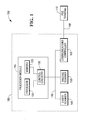
- Fig. 1 is a high-level block diagram illustrating an exemplar embodiment of a point-of-sale system
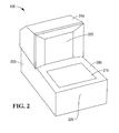
- Fig. 2 is a high-level drawing illustrating an exemplar embodiment of a hybrid optical code scanner
- Fig. 3A is a high-level cross-sectional drawing further illustrating the exemplar embodiment of the hybrid optical code scanner.
- Fig. 3B is a high-level drawing further illustrating the vertical scanning window of the hybrid optical code scanner.
- optical code includes both one and two dimensional barcodes as well as documents such as a driver's license or other forms of identification.
- FIG. 1 there is provided a high-level block diagram illustrating an exemplar embodiment of a point of sale (POS) system 100.
- the system 100 includes a hybrid optical code scanner ("hybrid scanner") 105 and a POS terminal 110 where both are connected by a computer network 160.
- the hybrid optical code scanner 105 includes a processor module 115, a laser scanner 145, an imaging scanner 150 and a communications controller 155.
- the processor 120 Within the processor module 115, there is included a processor 120, a memory 125 and control circuitry 130.
- the memory 125 includes both volatile and non-volatile memory.
- Software stored in the memory 125 is executed by the processor 120 which causes the processor 120 to control the devices and operation of the hybrid optical code scanner 105.
- the control circuitry 130 provides an interface between the processor 120 and the memory 125 and between the processor 120 a bus 140 used to communicate with other devices that comprise the hybrid optical code scanner 105 including but not limited to the laser scanner 145, imaging scanner 150 and communications controller 155.
- the laser scanner 145 includes a laser generation device ( Fig. 3A , 350), a laser beam directing device ( Fig. 3A , 360) for directing a laser beam ( Fig. 3A , 355) generated by the laser generation device ( Fig. 3A , 350) and a photo-detector ( Fig. 3A , 365) for detecting laser light reflected from an optical code back to the laser scanner 145.
- the laser scanner 145 also includes a pattern mirror ( Fig. 3A , 325) used to direct a laser beam ( Fig. 3A , 340) reflected by the laser beam directing device ( Fig. 3A , 360).
- the imaging scanner 150 includes an image capture device such as a CMOS image sensor. When an optical code is presented to the hybrid optical code scanner 105, the imaging scanner 150 captures an image of the optical code and processes the image to recover data encoded in the optical code.
- an image capture device such as a CMOS image sensor.
- the communications controller 155 includes hardware and software required to communicate with external devices over the computer network 160.
- the computer network 160 is implemented using an industry standard USB bus that connects the hybrid optical code scanner 105 to the POS terminal 110.
- the hybrid optical code scanner 105 includes a housing 200 comprising a vertical housing component 210 and horizontal housing component 205.
- the vertical housing component 210 includes vertical scanning window 220 and the horizontal housing component 205 includes a horizontal scanning window 215.
- the vertical scanning window 220 faces the front 225 of the hybrid optical code scanner 105.
- An operator/user of the hybrid optical code scanner 105 stands in front of the hybrid optical code scanner 105 facing the vertical scanning window 220 and moves optical codes ( Fig. 3A , 300) for scanning through a first volume of space ( Fig. 3A , 370) generally above the horizontal scanning window 215 and in front of the vertical scanning window 220.
- the imaging scanner 150 is shown as part of the vertical housing component 210. In some embodiments, the imaging scanner 150 is removable from the vertical housing component 210 and is operated as a hand held device to read optical codes. However, when the imaging scanner 150 is docked in the vertical housing component 210 it reads optical codes as depicted in this figure. In other embodiments, the imaging scanner 150 is positioned in different locations within the hybrid scanner 105 and maybe fixed or removable.
- the laser and imaging scanners each have an optimal area in space where an optical code located in this area has the highest probability of the being read by the scanner.
- the size and location of the optimal area is different for the laser and imaging scanner. Therefore, the area that works best for the imaging scanner, maybe work as well for the laser scanner and vise-versa.
- the imaging scanner's optimal area is the first volume of space 370, also known as the sweet spot.
- the pattern mirror 325 is one of a plurality of pattern mirrors (not shown).
- the pattern mirror 325 receives the laser beam 340 from a laser beam directing device 360 and reflects the laser beam 345 through the vertical scanning window 220 to an area in front of the vertical scanning window 220 and generally over the horizontal scanning window 215.
- the area the laser beam 345 is directed to may extend past the perimeter of the horizontal scanning window 215.
- the laser beam directing device 360 causes the laser beam 345 to move so that it scans a second volume of space.
- Laser scanners in general, are best suited to read one dimensional (1D) barcodes (which are included as an optical code).
- the optical code 300 which in this embodiment is a two dimensional (2D) barcode, is presented to the hybrid optical code scanner 150 to be read by the imaging scanner 150.
- a first image of the optical code 300 travels along a first path 320 through the vertical scanning window 220 to a mirror 315 where it is reflected along a second path 310 to the imaging scanner 150 and is captured for processing.
- the first path 320 is not a thin line like a laser beam but is a wider path that allows the imaging scanner 150 to capture a complete image of the optical code 300.
- the optical code 300 is positioned over the horizontal scanning window 215 and in front of the vertical scanning window 220 in the imaging scanner's 150 sweet spot 370.
- an optical code When an optical code is in the sweet spot 370, it will fall within the field of vision and depth of field for the imaging scanner 150. This means that the optical code will be visible and in focus when it is located in the sweet spot 370 and facing the vertical scanning window 220.
- an optically transparent material 375 such as an ultra-violet (UV) ink, is applied to the inside surface of the vertical scanning window 220.
- the material 375 is applied around a first area 380 that is defined as the area of the vertical scanning window 220 where the first path 320 passes through.
- the generally geometry of the area 380 is a square or rectangle (this is not a requirement) and the material 375 is applied round the perimeter of the area 380.
- the area 380 is simply a dot that identifies the center of the sweet spot 370 and the material 375 is applied over the dot.
- An ultra-violet light source 305 is included in the housing 200 and is in a location that allows it to illuminate the material 375 with UV light.
- the light source 305 is turned on and ultra-violet light from the light source 305 strikes the material 375 causing it to fluoresce, making the material 375 visible to the user of the hybrid optical code scanner 105.
- the ultra-violet light is reflected by one or more mirrors between the light source 305 and the material 375.
- the now visible material 375 provides a visual indication to the user of the location of the sweet spot 370.
- the sweet spot 370 for the imaging scanner 150 will be in front of the material 370 at about the same height above the horizontal scanning window 215.
- the material 375 is applied as a thin layer or band around the perimeter of the area 380.
- the width of the material 375 can vary but is wide enough so that the material 375 is easily visible to the user when it fluoresces.
- the material 370 is optically transparent when applied in a thin layer. In some embodiments, the material 375 is optically translucent when applied in a thin layer.
- the vertical scanning window 220 and the horizontal scanning window 215 are made out of a transparent material, such as polycarbonate, that has the intrinsic property of filtering out most or all UV light. By filtering out the UV light, the operator of the hybrid scanner 105 is protected.
- the window is constructed from multiple sheets of glass with polycarbonate film placed in between the glass sheets.
- Fig. 3B further illustrates the material 375 on the vertical scanning window 220.
- the sweet spot 370 is located slightly to the left of the center of the vertical scanning window 220.
- the material 375 is offset to left of center.
- the material 375 is applied in a continuous band around the area 380. In other embodiments, the material 375 is applied in other patterns such as just in the corners to form corner hash marks. Many patterns are possible as long as they indicate to the user the location of the sweet spot 370 for the imaging scanner 150.
Landscapes
- Physics & Mathematics (AREA)
- Electromagnetism (AREA)
- Engineering & Computer Science (AREA)
- Health & Medical Sciences (AREA)
- General Health & Medical Sciences (AREA)
- Toxicology (AREA)
- Artificial Intelligence (AREA)
- Computer Vision & Pattern Recognition (AREA)
- General Physics & Mathematics (AREA)
- Theoretical Computer Science (AREA)
- Cash Registers Or Receiving Machines (AREA)
- Image Input (AREA)
Abstract
Description
- The present invention relates generally to a hybrid optical code scanner. More particularly, but not exclusively, the invention relates to a scanner and system for identifying an optimal presentation location for an optical code.
- Any discussion of prior art throughout the specification should in no way be considered as an admission that such prior art is widely known or forms part of common general knowledge in the field.
- A hybrid optical code scanner includes a laser scanner and an imaging scanner. The two scanners are used to independently read optical codes such as barcodes presented to the scanner. The laser scanner reads a barcode by sweeping a laser beam across the barcode, capturing data representing the reflected laser light, and then processing the captured data. An imaging scanner reads a barcode by capturing a complete image of the barcode and then processing the image.
- When a barcode is presented to the imaging scanner, the barcode generally faces away from the operator and toward the imaging scanner. Even if the imaging scanner projects targeting marker beams that identify where to place the barcode (the sweet spot), the barcode or the item the barcode is attached to will block the operator's view of the beams. This makes the image scanning process essentially a blind operation.
- To complicate the process, the size of the preferred imaging location (sweet spot) can be small and its exact location is not intuitive to the operator. The combination of not knowing where to present a barcode and not being able to see targeting the marker beams, significantly reduces scan performance and reduces the shopping experience for the operator. The operator is typically a customer but could be an employee.
- Therefore, there is a need for a hybrid optical code scanner that provides an effective way to properly align optical codes with an imaging scanner of the hybrid optical code scanner.
- It is an object of the present invention to overcome or ameliorate at least one of the disadvantages of the prior art, or to provide a useful alternative.
- Among its several aspects, one embodiment of the present invention recognizes a condition where an operator or user of a hybrid optical code scanner ("hybrid scanner") has difficultly determining the optimal location for presenting an optical code to the hybrid scanner for imaging by an imaging scanner in the hybrid scanner. One aspect of the present invention provides a visual indicator to the operator that identifies the optimal location for presenting the optical code for scanning by the imaging scanner.
- The visual indicator is visible when the imaging scanner is in operation and is invisible when the imaging scanner is not operating.
- According to a first aspect of the present invention there is provided a hybrid optical code scanner comprising: a vertical scanning window; a laser scanner for reading optical codes where the laser scanner generates at least one laser scan beam that passes through the vertical scanning window; an imaging scanner for reading optical codes where the imaging scanner captures a image of an optical code that is positioned in a predetermined area in front of the vertical scanning window and where the space between the imaging scanner and the predetermined area forms a first image path; an ultra-violet light source; and a fluorescent material applied as a thin band to the inside surface of the vertical scanning window where the material fluoresces when exposed to ultra-violet light from the ultra-violet light source and where the thin band encompasses an area of the vertical scanning window that includes the portion of the first image path that passes through the vertical scanning window.
- The imaging scanner may normally be docked to, but is also removable from, a housing of the hybrid optical code scanner and is operable to read optical codes in either the docked or removed position.
- The ultra-violet light source is optionally turned on when the imaging scanner is operating causing the fluorescent material to fluoresce creating a visual indicator indicating the location of the predetermined area.
- The fluorescent material optionally fluoresces visible light.
- The visible light may be generally red in color.
- The optical code may be a barcode.
- The optical code may be an identification document.
- The vertical scanning window may be made of a transparent material that intrinsically filters out ultra-violet light.
- The fluorescent material may comprise an optically transparent or translucent.
- According to a second aspect of the present invention there is provided a point-of-sale system including: a point-of-sale terminal; a computer network; and a hybrid optical code scanner according to the first aspect of the invention, where the hybrid optical code scanner is connected to the point-of-sale terminal over the computer network,
- The imaging scanner may normally be docked to, but be removable from, the hybrid optical code scanner and may be operable to read optical codes in either the docked or removed position.
- The ultra-violet light source may be turned on when the imaging scanner is operating causing the fluorescent material to fluoresce creating a visual indicator indicating the location of the predetermined area.
- The optically translucent material optionally fluoresces a visible light.
- The visible translucent may be generally red in color.
- The optical code may be a barcode.
- The optical code may comprise an identification document.
- The vertical scanning window may be made of a transparent material that intrinsically filters out ultra-violet light.
- A more complete understanding of the present invention, as well as further features and advantages of the invention, will be apparent from the following specific description, with reference to the accompanying drawings:
-
Fig. 1 is a high-level block diagram illustrating an exemplar embodiment of a point-of-sale system; -
Fig. 2 is a high-level drawing illustrating an exemplar embodiment of a hybrid optical code scanner; -
Fig. 3A is a high-level cross-sectional drawing further illustrating the exemplar embodiment of the hybrid optical code scanner; and -
Fig. 3B is a high-level drawing further illustrating the vertical scanning window of the hybrid optical code scanner. - In the following description, numerous details are set forth to provide an understanding of the claimed invention. However, it will be understood by those skilled in the art that the claimed invention may be practiced without these details and that numerous variations or modifications from the described embodiments are possible. The drawings are not necessarily drawn to scale. Throughout the drawings, like element numbers are used to describe the same parts throughout the various drawings, figures and charts.
- The term optical code includes both one and two dimensional barcodes as well as documents such as a driver's license or other forms of identification.
- Referring now to
Fig. 1 , there is provided a high-level block diagram illustrating an exemplar embodiment of a point of sale (POS)system 100. Thesystem 100 includes a hybrid optical code scanner ("hybrid scanner") 105 and aPOS terminal 110 where both are connected by acomputer network 160. The hybridoptical code scanner 105 includes aprocessor module 115, alaser scanner 145, animaging scanner 150 and acommunications controller 155. - Within the
processor module 115, there is included aprocessor 120, amemory 125 andcontrol circuitry 130. Thememory 125 includes both volatile and non-volatile memory. Software stored in thememory 125 is executed by theprocessor 120 which causes theprocessor 120 to control the devices and operation of the hybridoptical code scanner 105. Thecontrol circuitry 130 provides an interface between theprocessor 120 and thememory 125 and between the processor 120 abus 140 used to communicate with other devices that comprise the hybridoptical code scanner 105 including but not limited to thelaser scanner 145,imaging scanner 150 andcommunications controller 155. - The
laser scanner 145 includes a laser generation device (Fig. 3A , 350), a laser beam directing device (Fig. 3A , 360) for directing a laser beam (Fig. 3A , 355) generated by the laser generation device (Fig. 3A , 350) and a photo-detector (Fig. 3A , 365) for detecting laser light reflected from an optical code back to thelaser scanner 145. Thelaser scanner 145 also includes a pattern mirror (Fig. 3A , 325) used to direct a laser beam (Fig. 3A , 340) reflected by the laser beam directing device (Fig. 3A , 360). - The
imaging scanner 150 includes an image capture device such as a CMOS image sensor. When an optical code is presented to the hybridoptical code scanner 105, theimaging scanner 150 captures an image of the optical code and processes the image to recover data encoded in the optical code. - The
communications controller 155 includes hardware and software required to communicate with external devices over thecomputer network 160. In some embodiments, thecomputer network 160 is implemented using an industry standard USB bus that connects the hybridoptical code scanner 105 to thePOS terminal 110. - Turning to
Fig. 2 , there is provided a high-level drawing illustrating an exemplar embodiment of the hybridoptical code scanner 105. The hybridoptical code scanner 105 includes ahousing 200 comprising avertical housing component 210 andhorizontal housing component 205. Thevertical housing component 210 includesvertical scanning window 220 and thehorizontal housing component 205 includes ahorizontal scanning window 215. Thevertical scanning window 220 faces thefront 225 of the hybridoptical code scanner 105. An operator/user of the hybridoptical code scanner 105 stands in front of the hybridoptical code scanner 105 facing thevertical scanning window 220 and moves optical codes (Fig. 3A , 300) for scanning through a first volume of space (Fig. 3A , 370) generally above thehorizontal scanning window 215 and in front of thevertical scanning window 220. - The
imaging scanner 150 is shown as part of thevertical housing component 210. In some embodiments, theimaging scanner 150 is removable from thevertical housing component 210 and is operated as a hand held device to read optical codes. However, when theimaging scanner 150 is docked in thevertical housing component 210 it reads optical codes as depicted in this figure. In other embodiments, theimaging scanner 150 is positioned in different locations within thehybrid scanner 105 and maybe fixed or removable. - The laser and imaging scanners each have an optimal area in space where an optical code located in this area has the highest probability of the being read by the scanner. The size and location of the optimal area is different for the laser and imaging scanner. Therefore, the area that works best for the imaging scanner, maybe work as well for the laser scanner and vise-versa. The imaging scanner's optimal area is the first volume of
space 370, also known as the sweet spot. - With reference to
Fig. 3A , there is provided a high-level cross-sectional drawing further illustrating the exemplar embodiment of the hybridoptical code scanner 105. Thepattern mirror 325 is one of a plurality of pattern mirrors (not shown). Thepattern mirror 325 receives thelaser beam 340 from a laserbeam directing device 360 and reflects thelaser beam 345 through thevertical scanning window 220 to an area in front of thevertical scanning window 220 and generally over thehorizontal scanning window 215. In some embodiments, the area thelaser beam 345 is directed to may extend past the perimeter of thehorizontal scanning window 215. The laserbeam directing device 360 causes thelaser beam 345 to move so that it scans a second volume of space. If thelaser beam 345 strikes and moves across an optical code, the reflected laser light is directed (directing devices not shown) back to thelaser scanner 145 where the laser light is detected to the photo-detector 365 and data encoded in the optical code read. Laser scanners, in general, are best suited to read one dimensional (1D) barcodes (which are included as an optical code). - The
optical code 300, which in this embodiment is a two dimensional (2D) barcode, is presented to the hybridoptical code scanner 150 to be read by theimaging scanner 150. A first image of theoptical code 300 travels along afirst path 320 through thevertical scanning window 220 to amirror 315 where it is reflected along asecond path 310 to theimaging scanner 150 and is captured for processing. Thefirst path 320 is not a thin line like a laser beam but is a wider path that allows theimaging scanner 150 to capture a complete image of theoptical code 300. - The
optical code 300 is positioned over thehorizontal scanning window 215 and in front of thevertical scanning window 220 in the imaging scanner's 150sweet spot 370. When an optical code is in thesweet spot 370, it will fall within the field of vision and depth of field for theimaging scanner 150. This means that the optical code will be visible and in focus when it is located in thesweet spot 370 and facing thevertical scanning window 220. - However, finding the
sweet spot 370 maybe difficult. To aid the user in finding thesweet spot 370, an opticallytransparent material 375, such as an ultra-violet (UV) ink, is applied to the inside surface of thevertical scanning window 220. Thematerial 375 is applied around afirst area 380 that is defined as the area of thevertical scanning window 220 where thefirst path 320 passes through. The generally geometry of thearea 380 is a square or rectangle (this is not a requirement) and thematerial 375 is applied round the perimeter of thearea 380. In some embodiments, thearea 380 is simply a dot that identifies the center of thesweet spot 370 and thematerial 375 is applied over the dot. An ultra-violetlight source 305 is included in thehousing 200 and is in a location that allows it to illuminate the material 375 with UV light. When theimaging scanner 150 is operating, thelight source 305 is turned on and ultra-violet light from thelight source 305 strikes thematerial 375 causing it to fluoresce, making the material 375 visible to the user of the hybridoptical code scanner 105. In some embodiments, the ultra-violet light is reflected by one or more mirrors between thelight source 305 and thematerial 375. The nowvisible material 375 provides a visual indication to the user of the location of thesweet spot 370. Thesweet spot 370 for theimaging scanner 150 will be in front of the material 370 at about the same height above thehorizontal scanning window 215. - The
material 375 is applied as a thin layer or band around the perimeter of thearea 380. The width of the material 375 can vary but is wide enough so that thematerial 375 is easily visible to the user when it fluoresces. Thematerial 370 is optically transparent when applied in a thin layer. In some embodiments, thematerial 375 is optically translucent when applied in a thin layer. - Since UV light can be harmful to humans, the
vertical scanning window 220 and thehorizontal scanning window 215 are made out of a transparent material, such as polycarbonate, that has the intrinsic property of filtering out most or all UV light. By filtering out the UV light, the operator of thehybrid scanner 105 is protected. In some embodiments, the window is constructed from multiple sheets of glass with polycarbonate film placed in between the glass sheets. -
Fig. 3B further illustrates thematerial 375 on thevertical scanning window 220. In this example, thesweet spot 370 is located slightly to the left of the center of thevertical scanning window 220. As a result, thematerial 375 is offset to left of center. - In this embodiment, the
material 375 is applied in a continuous band around thearea 380. In other embodiments, thematerial 375 is applied in other patterns such as just in the corners to form corner hash marks. Many patterns are possible as long as they indicate to the user the location of thesweet spot 370 for theimaging scanner 150. - Although particular reference has been made to an embodiment that includes a hybrid optical code scanner and examples have been provided illustrating the invention in combination with a laser and imaging scanner, certain other embodiments, variations and modifications are also envisioned within the spirit and scope of the following claims. For example, there are embodiments where the invention is used in scanners having only an imaging scanner.
Claims (9)
- A hybrid optical code scanner (105) comprising:a vertical scanning window (220);a laser scanner (145) for reading optical codes (300) where the laser scanner (145) generates at least one laser scan beam (345) that passes through the vertical scanning window (220);an imaging scanner (150) for reading optical codes (300) where the imaging scanner (150) captures a image of an optical code (300) that is positioned in a predetermined area (370) in front of the vertical scanning window (220) and where the space between the imaging scanner (150) and the predetermined area (370) forms a first image path (320);an ultra-violet light source(305); anda fluorescent material (375) applied as a thin band to the inside surface of the vertical scanning window (220) where the material fluoresces when exposed to ultra-violet light from the ultra-violet light source (305) and where the thin band encompasses an area of the vertical scanning window (220) that includes the portion of the first image path (320) that passes through the vertical scanning window (220).
- The hybrid optical code scanner of claim 1, where the imaging scanner (150) is normally docked to but is also removable from a housing (200) of the hybrid optical code scanner (105) and is operable to read optical codes (300) in either the docked or removed position.
- The hybrid optical code scanner of claim 1 or 2, where the ultra-violet light source (305) is turned on when the imaging scanner (150) is operating causing the fluorescent material (375) to fluoresce creating a visual indicator indicating the location of the predetermined area (370).
- The hybrid optical code scanner of any preceding claim, where the fluorescent material (375) fluoresces visible light.
- The hybrid optical code scanner of claim 4, where the visible light is generally red in colour.
- The hybrid optical code scanner of any preceding claim, where the optical code (300) is a barcode.
- The hybrid optical code scanner of any preceding claim, where the optical code (300) is an identification document.
- The hybrid optical code scanner of any preceding claim, where the vertical scanning window (220) is made of a transparent material that intrinsically filters out ultra-violet light.
- A point-of-sale system (100) including:a point-of-sale terminal (110);a computer network (160); anda hybrid optical code scanner (105) according to any preceding claim,
wherein the hybrid optical code scanner (105) is connected to the point-of-sale terminal (110) over the computer network (160).
Applications Claiming Priority (1)
| Application Number | Priority Date | Filing Date | Title |
|---|---|---|---|
| US13/248,831 US8479995B2 (en) | 2011-09-29 | 2011-09-29 | Hybrid optical code scanner and system |
Publications (2)
| Publication Number | Publication Date |
|---|---|
| EP2575075A1 true EP2575075A1 (en) | 2013-04-03 |
| EP2575075B1 EP2575075B1 (en) | 2017-03-15 |
Family
ID=46801318
Family Applications (1)
| Application Number | Title | Priority Date | Filing Date |
|---|---|---|---|
| EP12181573.2A Active EP2575075B1 (en) | 2011-09-29 | 2012-08-23 | A Hybrid Optical Code Scanner and System |
Country Status (2)
| Country | Link |
|---|---|
| US (1) | US8479995B2 (en) |
| EP (1) | EP2575075B1 (en) |
Families Citing this family (3)
| Publication number | Priority date | Publication date | Assignee | Title |
|---|---|---|---|---|
| US10650232B2 (en) | 2013-08-26 | 2020-05-12 | Ncr Corporation | Produce and non-produce verification using hybrid scanner |
| USD730901S1 (en) | 2014-06-24 | 2015-06-02 | Hand Held Products, Inc. | In-counter barcode scanner |
| CN105760866A (en) * | 2016-01-29 | 2016-07-13 | 北京爱创科技股份有限公司 | Laser coding identification and reading system and method |
Citations (4)
| Publication number | Priority date | Publication date | Assignee | Title |
|---|---|---|---|---|
| EP0661494A1 (en) * | 1993-12-28 | 1995-07-05 | LINTEC Corporation | A method of manufacturing a luminous sheet radiating florescence upon irradiation of ultraviolet rays |
| US20090084855A1 (en) * | 2007-10-02 | 2009-04-02 | Herwig Nathaniel C | Methods and Apparatus for Directing Bar Code Positioning for Imaging Scanning |
| WO2010045192A1 (en) * | 2008-10-16 | 2010-04-22 | Symbol Technologies, Inc. | Hybrid laser scanning and imaging reader |
| US20100147953A1 (en) * | 2008-12-15 | 2010-06-17 | Symbol Technologies, Inc. | Imaging of non-barcoded documents |
Family Cites Families (5)
| Publication number | Priority date | Publication date | Assignee | Title |
|---|---|---|---|---|
| US5475207A (en) * | 1992-07-14 | 1995-12-12 | Spectra-Physics Scanning Systems, Inc. | Multiple plane scanning system for data reading applications |
| US6003773A (en) * | 1996-03-01 | 1999-12-21 | Intermec Ip Corp. | Tablet style indicia reader with system for handling multiple indicia |
| US7337960B2 (en) * | 2004-02-27 | 2008-03-04 | Evolution Robotics, Inc. | Systems and methods for merchandise automatic checkout |
| US20060196948A1 (en) * | 2005-03-04 | 2006-09-07 | Weber Michael F | Light transmissive cards with suppression of UV-induced fluorescence |
| US7516899B2 (en) * | 2006-03-06 | 2009-04-14 | V.L. Engineering, Inc. | Hand held wireless reading viewer of invisible bar codes |
-
2011
- 2011-09-29 US US13/248,831 patent/US8479995B2/en active Active
-
2012
- 2012-08-23 EP EP12181573.2A patent/EP2575075B1/en active Active
Patent Citations (4)
| Publication number | Priority date | Publication date | Assignee | Title |
|---|---|---|---|---|
| EP0661494A1 (en) * | 1993-12-28 | 1995-07-05 | LINTEC Corporation | A method of manufacturing a luminous sheet radiating florescence upon irradiation of ultraviolet rays |
| US20090084855A1 (en) * | 2007-10-02 | 2009-04-02 | Herwig Nathaniel C | Methods and Apparatus for Directing Bar Code Positioning for Imaging Scanning |
| WO2010045192A1 (en) * | 2008-10-16 | 2010-04-22 | Symbol Technologies, Inc. | Hybrid laser scanning and imaging reader |
| US20100147953A1 (en) * | 2008-12-15 | 2010-06-17 | Symbol Technologies, Inc. | Imaging of non-barcoded documents |
Also Published As
| Publication number | Publication date |
|---|---|
| US20130082110A1 (en) | 2013-04-04 |
| EP2575075B1 (en) | 2017-03-15 |
| US8479995B2 (en) | 2013-07-09 |
Similar Documents
| Publication | Publication Date | Title |
|---|---|---|
| US8118227B2 (en) | Multiple camera imaging-based bar code reader with optimized imaging field | |
| EP2507741B1 (en) | Imaging-based scanner including border searching for image acquisition | |
| EP3496001A1 (en) | Indicia reader having a filtered multifunction image sensor | |
| CN108351955B (en) | Compact imaging module with rangefinder | |
| CN102197403A (en) | Bar code reader with split field of view | |
| US8740086B2 (en) | Apparatus for and method of reading indicia by using non-readily visible illumination light | |
| EP2600277B1 (en) | Determining the source of an optical code presented to an optical code scanner | |
| EP2727046B1 (en) | Individual exposure control over individually illuminated subfields of view split from an imager in a point-of-transaction workstation | |
| WO2011041125A1 (en) | Method and apparatus for intelligently controlling illumination patterns projected from barcode readers | |
| EP2344978B1 (en) | Selective working distance range restriction in imaging system | |
| US9298957B2 (en) | Detecting window deterioration on barcode scanning workstation | |
| EP2575075B1 (en) | A Hybrid Optical Code Scanner and System | |
| US20120273572A1 (en) | Point-of-transaction workstation for and method of imaging indicia over full coverage scan zone occupied by unskewed subfields of view | |
| US8002184B1 (en) | Bi-optical imaging point-of-transaction workstation with recessed upright window | |
| US9038903B2 (en) | Method and apparatus for controlling illumination | |
| US20130141584A1 (en) | Apparatus for and method of triggering electro-optical reading only when a target to be read is in a selected zone in a point-of-transaction workstation | |
| EP2370930B1 (en) | Minimizing misdecodes in electro-optical readers | |
| EP2140398B1 (en) | Image enhancement in imaging system | |
| US9483669B2 (en) | Barcode imaging workstation having sequentially activated object sensors | |
| US8292181B1 (en) | Apparatus and system for a hybrid optical code scanner | |
| US20150347798A1 (en) | Point-of-transaction workstation for, and method of, imaging sheet-like targets | |
| US20070175996A1 (en) | Imaging reader and method with tall field of view | |
| US12493761B2 (en) | Indicia readers with structure light assemblies | |
| JPH10187871A (en) | 2D code reader |
Legal Events
| Date | Code | Title | Description |
|---|---|---|---|
| PUAI | Public reference made under article 153(3) epc to a published international application that has entered the european phase |
Free format text: ORIGINAL CODE: 0009012 |
|
| AK | Designated contracting states |
Kind code of ref document: A1 Designated state(s): AL AT BE BG CH CY CZ DE DK EE ES FI FR GB GR HR HU IE IS IT LI LT LU LV MC MK MT NL NO PL PT RO RS SE SI SK SM TR |
|
| AX | Request for extension of the european patent |
Extension state: BA ME |
|
| 17P | Request for examination filed |
Effective date: 20131004 |
|
| RBV | Designated contracting states (corrected) |
Designated state(s): AL AT BE BG CH CY CZ DE DK EE ES FI FR GB GR HR HU IE IS IT LI LT LU LV MC MK MT NL NO PL PT RO RS SE SI SK SM TR |
|
| GRAP | Despatch of communication of intention to grant a patent |
Free format text: ORIGINAL CODE: EPIDOSNIGR1 |
|
| RIC1 | Information provided on ipc code assigned before grant |
Ipc: G06K 7/10 20060101AFI20161201BHEP Ipc: G06K 7/00 20060101ALI20161201BHEP |
|
| INTG | Intention to grant announced |
Effective date: 20170102 |
|
| GRAS | Grant fee paid |
Free format text: ORIGINAL CODE: EPIDOSNIGR3 |
|
| GRAA | (expected) grant |
Free format text: ORIGINAL CODE: 0009210 |
|
| AK | Designated contracting states |
Kind code of ref document: B1 Designated state(s): AL AT BE BG CH CY CZ DE DK EE ES FI FR GB GR HR HU IE IS IT LI LT LU LV MC MK MT NL NO PL PT RO RS SE SI SK SM TR |
|
| REG | Reference to a national code |
Ref country code: CH Ref legal event code: EP Ref country code: GB Ref legal event code: FG4D |
|
| REG | Reference to a national code |
Ref country code: DE Ref legal event code: R084 Ref document number: 602012029779 Country of ref document: DE |
|
| REG | Reference to a national code |
Ref country code: IE Ref legal event code: FG4D |
|
| REG | Reference to a national code |
Ref country code: GB Ref legal event code: 746 Effective date: 20170320 |
|
| REG | Reference to a national code |
Ref country code: AT Ref legal event code: REF Ref document number: 876253 Country of ref document: AT Kind code of ref document: T Effective date: 20170415 |
|
| REG | Reference to a national code |
Ref country code: DE Ref legal event code: R096 Ref document number: 602012029779 Country of ref document: DE |
|
| REG | Reference to a national code |
Ref country code: NL Ref legal event code: MP Effective date: 20170315 |
|
| REG | Reference to a national code |
Ref country code: LT Ref legal event code: MG4D |
|
| PG25 | Lapsed in a contracting state [announced via postgrant information from national office to epo] |
Ref country code: GR Free format text: LAPSE BECAUSE OF FAILURE TO SUBMIT A TRANSLATION OF THE DESCRIPTION OR TO PAY THE FEE WITHIN THE PRESCRIBED TIME-LIMIT Effective date: 20170616 Ref country code: NO Free format text: LAPSE BECAUSE OF FAILURE TO SUBMIT A TRANSLATION OF THE DESCRIPTION OR TO PAY THE FEE WITHIN THE PRESCRIBED TIME-LIMIT Effective date: 20170615 Ref country code: LT Free format text: LAPSE BECAUSE OF FAILURE TO SUBMIT A TRANSLATION OF THE DESCRIPTION OR TO PAY THE FEE WITHIN THE PRESCRIBED TIME-LIMIT Effective date: 20170315 Ref country code: FI Free format text: LAPSE BECAUSE OF FAILURE TO SUBMIT A TRANSLATION OF THE DESCRIPTION OR TO PAY THE FEE WITHIN THE PRESCRIBED TIME-LIMIT Effective date: 20170315 Ref country code: HR Free format text: LAPSE BECAUSE OF FAILURE TO SUBMIT A TRANSLATION OF THE DESCRIPTION OR TO PAY THE FEE WITHIN THE PRESCRIBED TIME-LIMIT Effective date: 20170315 |
|
| REG | Reference to a national code |
Ref country code: AT Ref legal event code: MK05 Ref document number: 876253 Country of ref document: AT Kind code of ref document: T Effective date: 20170315 |
|
| REG | Reference to a national code |
Ref country code: FR Ref legal event code: PLFP Year of fee payment: 6 |
|
| PG25 | Lapsed in a contracting state [announced via postgrant information from national office to epo] |
Ref country code: LV Free format text: LAPSE BECAUSE OF FAILURE TO SUBMIT A TRANSLATION OF THE DESCRIPTION OR TO PAY THE FEE WITHIN THE PRESCRIBED TIME-LIMIT Effective date: 20170315 Ref country code: BG Free format text: LAPSE BECAUSE OF FAILURE TO SUBMIT A TRANSLATION OF THE DESCRIPTION OR TO PAY THE FEE WITHIN THE PRESCRIBED TIME-LIMIT Effective date: 20170615 Ref country code: RS Free format text: LAPSE BECAUSE OF FAILURE TO SUBMIT A TRANSLATION OF THE DESCRIPTION OR TO PAY THE FEE WITHIN THE PRESCRIBED TIME-LIMIT Effective date: 20170315 Ref country code: SE Free format text: LAPSE BECAUSE OF FAILURE TO SUBMIT A TRANSLATION OF THE DESCRIPTION OR TO PAY THE FEE WITHIN THE PRESCRIBED TIME-LIMIT Effective date: 20170315 |
|
| PG25 | Lapsed in a contracting state [announced via postgrant information from national office to epo] |
Ref country code: NL Free format text: LAPSE BECAUSE OF FAILURE TO SUBMIT A TRANSLATION OF THE DESCRIPTION OR TO PAY THE FEE WITHIN THE PRESCRIBED TIME-LIMIT Effective date: 20170315 |
|
| PG25 | Lapsed in a contracting state [announced via postgrant information from national office to epo] |
Ref country code: RO Free format text: LAPSE BECAUSE OF FAILURE TO SUBMIT A TRANSLATION OF THE DESCRIPTION OR TO PAY THE FEE WITHIN THE PRESCRIBED TIME-LIMIT Effective date: 20170315 Ref country code: AT Free format text: LAPSE BECAUSE OF FAILURE TO SUBMIT A TRANSLATION OF THE DESCRIPTION OR TO PAY THE FEE WITHIN THE PRESCRIBED TIME-LIMIT Effective date: 20170315 Ref country code: SK Free format text: LAPSE BECAUSE OF FAILURE TO SUBMIT A TRANSLATION OF THE DESCRIPTION OR TO PAY THE FEE WITHIN THE PRESCRIBED TIME-LIMIT Effective date: 20170315 Ref country code: IT Free format text: LAPSE BECAUSE OF FAILURE TO SUBMIT A TRANSLATION OF THE DESCRIPTION OR TO PAY THE FEE WITHIN THE PRESCRIBED TIME-LIMIT Effective date: 20170315 Ref country code: CZ Free format text: LAPSE BECAUSE OF FAILURE TO SUBMIT A TRANSLATION OF THE DESCRIPTION OR TO PAY THE FEE WITHIN THE PRESCRIBED TIME-LIMIT Effective date: 20170315 Ref country code: EE Free format text: LAPSE BECAUSE OF FAILURE TO SUBMIT A TRANSLATION OF THE DESCRIPTION OR TO PAY THE FEE WITHIN THE PRESCRIBED TIME-LIMIT Effective date: 20170315 Ref country code: ES Free format text: LAPSE BECAUSE OF FAILURE TO SUBMIT A TRANSLATION OF THE DESCRIPTION OR TO PAY THE FEE WITHIN THE PRESCRIBED TIME-LIMIT Effective date: 20170315 |
|
| PG25 | Lapsed in a contracting state [announced via postgrant information from national office to epo] |
Ref country code: SM Free format text: LAPSE BECAUSE OF FAILURE TO SUBMIT A TRANSLATION OF THE DESCRIPTION OR TO PAY THE FEE WITHIN THE PRESCRIBED TIME-LIMIT Effective date: 20170315 Ref country code: PT Free format text: LAPSE BECAUSE OF FAILURE TO SUBMIT A TRANSLATION OF THE DESCRIPTION OR TO PAY THE FEE WITHIN THE PRESCRIBED TIME-LIMIT Effective date: 20170717 Ref country code: PL Free format text: LAPSE BECAUSE OF FAILURE TO SUBMIT A TRANSLATION OF THE DESCRIPTION OR TO PAY THE FEE WITHIN THE PRESCRIBED TIME-LIMIT Effective date: 20170315 Ref country code: IS Free format text: LAPSE BECAUSE OF FAILURE TO SUBMIT A TRANSLATION OF THE DESCRIPTION OR TO PAY THE FEE WITHIN THE PRESCRIBED TIME-LIMIT Effective date: 20170715 |
|
| REG | Reference to a national code |
Ref country code: DE Ref legal event code: R097 Ref document number: 602012029779 Country of ref document: DE |
|
| PLBE | No opposition filed within time limit |
Free format text: ORIGINAL CODE: 0009261 |
|
| STAA | Information on the status of an ep patent application or granted ep patent |
Free format text: STATUS: NO OPPOSITION FILED WITHIN TIME LIMIT |
|
| PG25 | Lapsed in a contracting state [announced via postgrant information from national office to epo] |
Ref country code: DK Free format text: LAPSE BECAUSE OF FAILURE TO SUBMIT A TRANSLATION OF THE DESCRIPTION OR TO PAY THE FEE WITHIN THE PRESCRIBED TIME-LIMIT Effective date: 20170315 |
|
| 26N | No opposition filed |
Effective date: 20171218 |
|
| PG25 | Lapsed in a contracting state [announced via postgrant information from national office to epo] |
Ref country code: SI Free format text: LAPSE BECAUSE OF FAILURE TO SUBMIT A TRANSLATION OF THE DESCRIPTION OR TO PAY THE FEE WITHIN THE PRESCRIBED TIME-LIMIT Effective date: 20170315 |
|
| REG | Reference to a national code |
Ref country code: CH Ref legal event code: PL |
|
| PG25 | Lapsed in a contracting state [announced via postgrant information from national office to epo] |
Ref country code: MC Free format text: LAPSE BECAUSE OF FAILURE TO SUBMIT A TRANSLATION OF THE DESCRIPTION OR TO PAY THE FEE WITHIN THE PRESCRIBED TIME-LIMIT Effective date: 20170315 |
|
| PG25 | Lapsed in a contracting state [announced via postgrant information from national office to epo] |
Ref country code: CH Free format text: LAPSE BECAUSE OF NON-PAYMENT OF DUE FEES Effective date: 20170831 Ref country code: LI Free format text: LAPSE BECAUSE OF NON-PAYMENT OF DUE FEES Effective date: 20170831 |
|
| REG | Reference to a national code |
Ref country code: IE Ref legal event code: MM4A |
|
| REG | Reference to a national code |
Ref country code: BE Ref legal event code: MM Effective date: 20170831 |
|
| PG25 | Lapsed in a contracting state [announced via postgrant information from national office to epo] |
Ref country code: LU Free format text: LAPSE BECAUSE OF NON-PAYMENT OF DUE FEES Effective date: 20170823 |
|
| PG25 | Lapsed in a contracting state [announced via postgrant information from national office to epo] |
Ref country code: IE Free format text: LAPSE BECAUSE OF NON-PAYMENT OF DUE FEES Effective date: 20170823 |
|
| REG | Reference to a national code |
Ref country code: FR Ref legal event code: PLFP Year of fee payment: 7 |
|
| PG25 | Lapsed in a contracting state [announced via postgrant information from national office to epo] |
Ref country code: BE Free format text: LAPSE BECAUSE OF NON-PAYMENT OF DUE FEES Effective date: 20170831 |
|
| PG25 | Lapsed in a contracting state [announced via postgrant information from national office to epo] |
Ref country code: MT Free format text: LAPSE BECAUSE OF NON-PAYMENT OF DUE FEES Effective date: 20170823 |
|
| PG25 | Lapsed in a contracting state [announced via postgrant information from national office to epo] |
Ref country code: HU Free format text: LAPSE BECAUSE OF FAILURE TO SUBMIT A TRANSLATION OF THE DESCRIPTION OR TO PAY THE FEE WITHIN THE PRESCRIBED TIME-LIMIT; INVALID AB INITIO Effective date: 20120823 |
|
| PG25 | Lapsed in a contracting state [announced via postgrant information from national office to epo] |
Ref country code: CY Free format text: LAPSE BECAUSE OF NON-PAYMENT OF DUE FEES Effective date: 20170315 |
|
| PG25 | Lapsed in a contracting state [announced via postgrant information from national office to epo] |
Ref country code: MK Free format text: LAPSE BECAUSE OF FAILURE TO SUBMIT A TRANSLATION OF THE DESCRIPTION OR TO PAY THE FEE WITHIN THE PRESCRIBED TIME-LIMIT Effective date: 20170315 |
|
| REG | Reference to a national code |
Ref country code: DE Ref legal event code: R081 Ref document number: 602012029779 Country of ref document: DE Owner name: NCR VOYIX CORP., ATLANTA, US Free format text: FORMER OWNER: NCR CORPORATION, DULUTH, GA., US Ref country code: DE Ref legal event code: R082 Ref document number: 602012029779 Country of ref document: DE Representative=s name: V. BEZOLD & PARTNER PATENTANWAELTE - PARTG MBB, DE Ref country code: DE Ref legal event code: R081 Ref document number: 602012029779 Country of ref document: DE Owner name: NCR CORPORATION, ATLANTA, US Free format text: FORMER OWNER: NCR CORPORATION, DULUTH, GA., US |
|
| PG25 | Lapsed in a contracting state [announced via postgrant information from national office to epo] |
Ref country code: TR Free format text: LAPSE BECAUSE OF FAILURE TO SUBMIT A TRANSLATION OF THE DESCRIPTION OR TO PAY THE FEE WITHIN THE PRESCRIBED TIME-LIMIT Effective date: 20170315 |
|
| PG25 | Lapsed in a contracting state [announced via postgrant information from national office to epo] |
Ref country code: AL Free format text: LAPSE BECAUSE OF FAILURE TO SUBMIT A TRANSLATION OF THE DESCRIPTION OR TO PAY THE FEE WITHIN THE PRESCRIBED TIME-LIMIT Effective date: 20170315 |
|
| P01 | Opt-out of the competence of the unified patent court (upc) registered |
Effective date: 20230507 |
|
| REG | Reference to a national code |
Ref country code: DE Ref legal event code: R081 Ref document number: 602012029779 Country of ref document: DE Owner name: NCR VOYIX CORP., ATLANTA, US Free format text: FORMER OWNER: NCR CORPORATION, ATLANTA, GA, US |
|
| PGFP | Annual fee paid to national office [announced via postgrant information from national office to epo] |
Ref country code: DE Payment date: 20250827 Year of fee payment: 14 |
|
| PGFP | Annual fee paid to national office [announced via postgrant information from national office to epo] |
Ref country code: GB Payment date: 20250827 Year of fee payment: 14 |
|
| PGFP | Annual fee paid to national office [announced via postgrant information from national office to epo] |
Ref country code: FR Payment date: 20250825 Year of fee payment: 14 |