EP2574941A2 - Method of estimating location of partial discharge using signal attenuation rate in GIS tank - Google Patents
Method of estimating location of partial discharge using signal attenuation rate in GIS tank Download PDFInfo
- Publication number
- EP2574941A2 EP2574941A2 EP12186651A EP12186651A EP2574941A2 EP 2574941 A2 EP2574941 A2 EP 2574941A2 EP 12186651 A EP12186651 A EP 12186651A EP 12186651 A EP12186651 A EP 12186651A EP 2574941 A2 EP2574941 A2 EP 2574941A2
- Authority
- EP
- European Patent Office
- Prior art keywords
- gis
- partial discharge
- attenuation rate
- tank
- signal
- Prior art date
- Legal status (The legal status is an assumption and is not a legal conclusion. Google has not performed a legal analysis and makes no representation as to the accuracy of the status listed.)
- Withdrawn
Links
- 238000000034 method Methods 0.000 title claims abstract description 71
- 230000002238 attenuated effect Effects 0.000 claims description 4
- 238000003745 diagnosis Methods 0.000 description 6
- 230000003449 preventive effect Effects 0.000 description 6
- 230000007547 defect Effects 0.000 description 4
- 238000005259 measurement Methods 0.000 description 2
- 239000002245 particle Substances 0.000 description 2
- 230000015556 catabolic process Effects 0.000 description 1
- 238000004891 communication Methods 0.000 description 1
- 238000013461 design Methods 0.000 description 1
- 238000013154 diagnostic monitoring Methods 0.000 description 1
- 238000012986 modification Methods 0.000 description 1
- 230000004048 modification Effects 0.000 description 1
- 238000012545 processing Methods 0.000 description 1
- 239000000725 suspension Substances 0.000 description 1
Images



Classifications
-
- G—PHYSICS
- G01—MEASURING; TESTING
- G01R—MEASURING ELECTRIC VARIABLES; MEASURING MAGNETIC VARIABLES
- G01R31/00—Arrangements for testing electric properties; Arrangements for locating electric faults; Arrangements for electrical testing characterised by what is being tested not provided for elsewhere
- G01R31/12—Testing dielectric strength or breakdown voltage ; Testing or monitoring effectiveness or level of insulation, e.g. of a cable or of an apparatus, for example using partial discharge measurements; Electrostatic testing
- G01R31/1227—Testing dielectric strength or breakdown voltage ; Testing or monitoring effectiveness or level of insulation, e.g. of a cable or of an apparatus, for example using partial discharge measurements; Electrostatic testing of components, parts or materials
- G01R31/1254—Testing dielectric strength or breakdown voltage ; Testing or monitoring effectiveness or level of insulation, e.g. of a cable or of an apparatus, for example using partial discharge measurements; Electrostatic testing of components, parts or materials of gas-insulated power appliances or vacuum gaps
-
- G—PHYSICS
- G01—MEASURING; TESTING
- G01R—MEASURING ELECTRIC VARIABLES; MEASURING MAGNETIC VARIABLES
- G01R31/00—Arrangements for testing electric properties; Arrangements for locating electric faults; Arrangements for electrical testing characterised by what is being tested not provided for elsewhere
- G01R31/08—Locating faults in cables, transmission lines, or networks
-
- G—PHYSICS
- G01—MEASURING; TESTING
- G01R—MEASURING ELECTRIC VARIABLES; MEASURING MAGNETIC VARIABLES
- G01R31/00—Arrangements for testing electric properties; Arrangements for locating electric faults; Arrangements for electrical testing characterised by what is being tested not provided for elsewhere
- G01R31/12—Testing dielectric strength or breakdown voltage ; Testing or monitoring effectiveness or level of insulation, e.g. of a cable or of an apparatus, for example using partial discharge measurements; Electrostatic testing
- G01R31/1227—Testing dielectric strength or breakdown voltage ; Testing or monitoring effectiveness or level of insulation, e.g. of a cable or of an apparatus, for example using partial discharge measurements; Electrostatic testing of components, parts or materials
- G01R31/1263—Testing dielectric strength or breakdown voltage ; Testing or monitoring effectiveness or level of insulation, e.g. of a cable or of an apparatus, for example using partial discharge measurements; Electrostatic testing of components, parts or materials of solid or fluid materials, e.g. insulation films, bulk material; of semiconductors or LV electronic components or parts; of cable, line or wire insulation
- G01R31/1272—Testing dielectric strength or breakdown voltage ; Testing or monitoring effectiveness or level of insulation, e.g. of a cable or of an apparatus, for example using partial discharge measurements; Electrostatic testing of components, parts or materials of solid or fluid materials, e.g. insulation films, bulk material; of semiconductors or LV electronic components or parts; of cable, line or wire insulation of cable, line or wire insulation, e.g. using partial discharge measurements
-
- Y—GENERAL TAGGING OF NEW TECHNOLOGICAL DEVELOPMENTS; GENERAL TAGGING OF CROSS-SECTIONAL TECHNOLOGIES SPANNING OVER SEVERAL SECTIONS OF THE IPC; TECHNICAL SUBJECTS COVERED BY FORMER USPC CROSS-REFERENCE ART COLLECTIONS [XRACs] AND DIGESTS
- Y04—INFORMATION OR COMMUNICATION TECHNOLOGIES HAVING AN IMPACT ON OTHER TECHNOLOGY AREAS
- Y04S—SYSTEMS INTEGRATING TECHNOLOGIES RELATED TO POWER NETWORK OPERATION, COMMUNICATION OR INFORMATION TECHNOLOGIES FOR IMPROVING THE ELECTRICAL POWER GENERATION, TRANSMISSION, DISTRIBUTION, MANAGEMENT OR USAGE, i.e. SMART GRIDS
- Y04S10/00—Systems supporting electrical power generation, transmission or distribution
- Y04S10/30—State monitoring, e.g. fault, temperature monitoring, insulator monitoring, corona discharge
Definitions
- the present invention relates to an external communication method of an on-line gas insulated switchgear (GIS), and more particularly, to a method of estimating a location of partial discharge using a signal attenuation rate in a GIS tank, capable of measuring an electromagnetic wave signal attenuation rate of each structure constituting a GIS, and estimating the location of partial discharge when the partial discharge occurs in the GIS.
- GIS on-line gas insulated switchgear
- GIS gas insulated switchgear
- Such a GIS preventive diagnosis system is a system that measures the leakage of insulating gas or the partial discharge that is an indication of electrical breakdown, thereby informing of a cause of failure in a rapid and accurate way.
- an internally mounted partial discharge sensor capable of measuring the partial discharge should be attached when the GIS is delivered.
- an internally mounted partial discharge sensor capable of measuring the partial discharge.
- the GIS preventive diagnosis system was first developed in 1992 by DMS (Diagnostic Monitoring Systems Ltd.), and has been developed by numerous small-and-medium preventive diagnosis enterprises including Hyundai Heavy Industries, Hyosung Power & Industrial Systems Performance Group, LS Industrial Systems, SIEMENS, ABB, etc. which are domestic and foreign GIS manufacturers.
- GIS preventive diagnosis systems merely analyze and diagnose defect causes with regard to a temporary partial discharge phenomenon, and fail to provide the interpretation of a partial discharge signal depending on a GIS internal structure, location information about a partial discharge source, and so on.
- a method of diagnosing the defect causes of the partial discharge has a limitation in that, when the partial discharge occurs, an on-site engineer of the GIS undergoing the partial discharge understands only the partial discharge phenomenon, and does not present a correct countermeasure of how to cope with the partial discharge.
- the present invention is directed to develop a function capable of measuring an electromagnetic wave signal attenuation rate of each structure constituting the GIS, and estimating the location of the partial discharge when the partial discharge occurs in the GIS on the basis of the measured attenuation rate, and to apply the function to a system.
- the present invention provides a method of estimating a location of partial discharge using a signal attenuation rate in a gas insulated switchgear (GIS) tank, by which a function capable of measuring an electromagnetic wave signal attenuation rate of each structure constituting a GIS and estimating the location of the partial discharge when the partial discharge occurs in the GIS on the basis of the measured attenuation rate can be developed and applied to a system.
- GIS gas insulated switchgear
- a method of estimating a location of partial discharge using a signal attenuation rate in a gas insulated switchgear (GIS) tank includes a process (S100) of constructing a coordinate system database of each tank of the GIS, a process (S200) of constructing an electromagnetic wave signal attenuation rate database of each structure of a GIS, a process (S300) of performing a location estimating algorithm by detecting a partial discharge signal of each structure using two sensors installed on the structure of each tank when the partial discharge occurs in the GIS, selecting the two sensors on the structure in which the partial discharge signal has a strongest intensity, and comparing the electromagnetic wave attenuation rate database of each structure of the GIS and the detected values of the two selected sensors to determine location coordinates of the tank at which the partial discharge occurs, and a process (S400) of comparing the location coordinates of the tank at which the partial discharge occurs through a result of performing the algorithm with the electromagnetic wave attenuation rate database, and determining the tank at which
- the process (S100) of constructing the coordinate system database of each tank of the GIS may include a process (S110) of checking a location of each tank using a drawing of the GIS, and a process (S120) of building up relative coordinates of each tank whose location is checked.
- the process (S200) of constructing the electromagnetic wave attenuation rate database of each structure of the GIS may include a process (S210) of measuring a partial discharge attenuation rate of each structure of the GIS, and a process (S220) of constructing a partial discharge attenuation rate database of each structure of the GIS using the measured attenuation rate.
- the process (S210) of measuring the partial discharge attenuation rate of each structure of the GIS may include mounting two externally mounted ultra high frequency (UHF) sensors (A and B) on the GIS, and inputting a UHF signal from a partial discharge generator into the GIS via an internally mounted sensor, and measuring a UHF signal attenuation rate at which, while the input signal is passing through a section (M) between the sensors (A and B), an intensity of the input signal is attenuated from Q A (an intensity of the UHF signal measured just before the GIS section (M) for measuring the attenuation rate) to Q B (an intensity of the UHF signal passing through the GIS section (M) for measuring the attenuation rate).
- UHF ultra high frequency
- a location of a partial discharge source may be estimated to be a point at which Q A (x) and Q B (x) join each other.
- the present invention has an advantage that it is capable of measuring the electromagnetic wave signal attenuation rate of each structure constituting the GIS and easily estimating the location of the partial discharge when the partial discharge occurs in the GIS on the basis of the result of the measurement.
- FIG. 1 shows a flow of processing a method of estimating a location of partial discharge using a signal attenuation rate in a GIS tank in accordance with the present invention
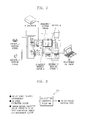
- FIG. 2 shows a state in which two externally mounted UHF sensors A and B are mounted on a GIS in the method of estimating a location of partial discharge using a signal attenuation rate in a GIS tank in accordance with the present invention
- FIG. 3 schematically shows a partial discharge location estimating algorithm in the method of estimating a location of partial discharge using a signal attenuation rate in a GIS tank in accordance with the present invention
- FIG. 4 shows a GIS model that is expressed by simplification as a set of structures having an attenuation rate and a distance in the method of estimating a location of partial discharge using a signal attenuation rate in a GIS tank in accordance with the present invention
- FIG. 5 shows a typical GIS attenuation model between two sensors in the method of estimating a location of partial discharge using a signal attenuation rate in a GIS tank in accordance with the present invention
- FIG. 6 is a graph showing an attenuation signal according to each GIS distance between two sensors in the method of estimating a location of partial discharge using a signal attenuation rate in a GIS tank in accordance with the present invention.
- a method of estimating a location of partial discharge using a signal attenuation rate in a gas insulated switchgear (GIS) tank in accordance with the present invention is configured to measure a signal attenuation rate of each structure of a GIS to generate a database, to develop an algorithm for estimating the location of partial discharge when the partial discharge occurs in the GIS using the generated attenuation rate database, and to estimate the location.
- GIS gas insulated switchgear
- an ultra high frequency (UHF) sensor is attached to an interior or an exterior of the GIS tank, and a partial discharge signal is acquired. Thereby, it is checked whether or not the partial discharge occurs in the GIS.
- UHF ultra high frequency
- a difference in intensity of the partial discharge signal reaching two sensors is used.
- the intensity of the partial discharge signal is attenuated in the process of passing through each structure of the GIS.
- a method of previously analyzing an attenuation rate pattern of each structure of the GIS, making the analyzed attenuation rate pattern into a database, and applying this database is employed.
- the method of estimating a location of partial discharge using a signal attenuation rate in a GIS tank in accordance with the present invention includes a process S100 of constructing a coordinate system database of each tank of the GIS, as shown in FIG 1 .
- the process S100 of constructing a coordinate system database of each tank of the GIS may include a process S110 of checking a location of each tank using a drawing of the GIS, and a process S120 of building up relative coordinates of each tank whose location is checked.
- the process S200 of constructing an electromagnetic wave attenuation rate database of each structure of the GIS may include a process S210 of measuring a partial discharge attenuation rate of each structure of the GIS, and a process S220 of constructing a partial discharge attenuation rate database of each structure of the GIS using the measured attenuation rate.
- the process S210 of measuring the partial discharge attenuation rate of each structure of the GIS is configured to mount two externally mounted UHF sensors A and B on the structure of each tank of the GIS, and to input a UHF signal from a partial discharge generator into the GIS via an internally mounted sensor.
- an intensity of the input signal is attenuated from Q A (an intensity of the UHF signal measured just before the GIS section M for measuring the attenuation rate) to Q B (an intensity of the UHF signal passing through the GIS section M for measuring the attenuation rate).
- Q A an intensity of the UHF signal measured just before the GIS section M for measuring the attenuation rate
- Q B an intensity of the UHF signal passing through the GIS section M for measuring the attenuation rate
- Q A is the intensity of the UHF signal measured just before the GIS section (section M of FIG. 2 ) for measuring the attenuation rate
- Q B is the intensity of the UHF signal passing through the GIS section (section M of FIG. 2 ) for measuring the attenuation rate
- L is the length of the GIS section (section M of FIG. 2 ) for measuring the attenuation rate
- ⁇ is the UHF signal attenuation rate.
- a partial discharge signal of each structure is detected by two sensors installed on the structure of each tank, and the two sensors on the structure in which the partial discharge signal has a strongest intensity are selected (S320). Then, the electromagnetic wave attenuation rate database of each structure of the GIS and the detected values of the two selected sensors are compared to determine location coordinates of the tank at which the partial discharge occurs (S330). In this way, the process S300 of performing the location estimating algorithm is advanced.
- a location of a partial discharge source can be estimated to be a point at which the two functions Q A (x) and Q B (x) intersect each other.
- a process S400 of comparing the location coordinates of the tank at which the partial discharge occurs through a result of performing the algorithm with the electromagnetic wave attenuation rate database of each structure of the GIS, and determining the tank at which the partial discharge occurs is advanced.
- the present invention has an advantage that it is capable of measuring the electromagnetic wave signal attenuation rate of each structure constituting the GIS and easily estimating the location of the partial discharge when the partial discharge occurs in the GIS on the basis of the result of the measurement.
Landscapes
- Physics & Mathematics (AREA)
- General Physics & Mathematics (AREA)
- Testing Relating To Insulation (AREA)
- Supply And Distribution Of Alternating Current (AREA)
Abstract
Description
- The present invention relates to an external communication method of an on-line gas insulated switchgear (GIS), and more particularly, to a method of estimating a location of partial discharge using a signal attenuation rate in a GIS tank, capable of measuring an electromagnetic wave signal attenuation rate of each structure constituting a GIS, and estimating the location of partial discharge when the partial discharge occurs in the GIS.
- A gas insulated switchgear (GIS) is important equipment that controls a high-voltage power system. Defects of GIS serve as one of factors causing serious power-off disturbance. Since this is responsible for an enormous loss to the economy, a system capable of preventing this condition is required.
- Such a GIS preventive diagnosis system is a system that measures the leakage of insulating gas or the partial discharge that is an indication of electrical breakdown, thereby informing of a cause of failure in a rapid and accurate way.
- Currently, with regard to new GISs having a design voltage of 170 kV or more, an internally mounted partial discharge sensor capable of measuring the partial discharge should be attached when the GIS is delivered. In the case of previously installed GISs, there shows a tendency to attach an internally or externally mounted partial discharge sensor according to a plan of suspension of power supply. In this way, the importance of a GIS preventive diagnosis function is enhanced as time goes on.
- Further, as the distribution of the GIS preventive diagnosis system gradually increases, the requests of customers with regard to knowledge of the partial discharge, countermeasures when the partial discharge occurs, etc., are increasing.
- The GIS preventive diagnosis system was first developed in 1992 by DMS (Diagnostic Monitoring Systems Ltd.), and has been developed by numerous small-and-medium preventive diagnosis enterprises including Hyundai Heavy Industries, Hyosung Power & Industrial Systems Performance Group, LS Industrial Systems, SIEMENS, ABB, etc. which are domestic and foreign GIS manufacturers.
- However, all the GIS preventive diagnosis systems merely analyze and diagnose defect causes with regard to a temporary partial discharge phenomenon, and fail to provide the interpretation of a partial discharge signal depending on a GIS internal structure, location information about a partial discharge source, and so on.
- Furthermore, a method of diagnosing the defect causes of the partial discharge has a limitation in that, when the partial discharge occurs, an on-site engineer of the GIS undergoing the partial discharge understands only the partial discharge phenomenon, and does not present a correct countermeasure of how to cope with the partial discharge.
- For example, when the partial discharge whose defect cause is diagnosed as a particle occurs, it is impossible to accurately detect in which tank of the GIS the particle is located, and thus to immediately cope with the partial discharge. To check a location at which the partial discharge occurs, an engineer should measure the location using an externally mounted sensor and an oscilloscope with additional time and cost.
- For this reason, to estimate the location of the partial discharge, it additionally takes a greater annual cost. Requests to include a function capable of estimating the location of the partial discharge when the partial discharge occurs continue to be made on site when GISs are delivered.
- For this reason, it is essential to develop a technique for estimating the location of the partial discharge. Accordingly, the present invention is directed to develop a function capable of measuring an electromagnetic wave signal attenuation rate of each structure constituting the GIS, and estimating the location of the partial discharge when the partial discharge occurs in the GIS on the basis of the measured attenuation rate, and to apply the function to a system.
- The present invention provides a method of estimating a location of partial discharge using a signal attenuation rate in a gas insulated switchgear (GIS) tank, by which a function capable of measuring an electromagnetic wave signal attenuation rate of each structure constituting a GIS and estimating the location of the partial discharge when the partial discharge occurs in the GIS on the basis of the measured attenuation rate can be developed and applied to a system.
According to one aspect of the present invention, a method of estimating a location of partial discharge using a signal attenuation rate in a gas insulated switchgear (GIS) tank includes a process (S100) of constructing a coordinate system database of each tank of the GIS, a process (S200) of constructing an electromagnetic wave signal attenuation rate database of each structure of a GIS, a process (S300) of performing a location estimating algorithm by detecting a partial discharge signal of each structure using two sensors installed on the structure of each tank when the partial discharge occurs in the GIS, selecting the two sensors on the structure in which the partial discharge signal has a strongest intensity, and comparing the electromagnetic wave attenuation rate database of each structure of the GIS and the detected values of the two selected sensors to determine location coordinates of the tank at which the partial discharge occurs, and a process (S400) of comparing the location coordinates of the tank at which the partial discharge occurs through a result of performing the algorithm with the electromagnetic wave attenuation rate database, and determining the tank at which the partial discharge occurs - Here, the process (S100) of constructing the coordinate system database of each tank of the GIS may include a process (S110) of checking a location of each tank using a drawing of the GIS, and a process (S120) of building up relative coordinates of each tank whose location is checked.
- Further, the process (S200) of constructing the electromagnetic wave attenuation rate database of each structure of the GIS may include a process (S210) of measuring a partial discharge attenuation rate of each structure of the GIS, and a process (S220) of constructing a partial discharge attenuation rate database of each structure of the GIS using the measured attenuation rate.
- Also, the process (S210) of measuring the partial discharge attenuation rate of each structure of the GIS may include mounting two externally mounted ultra high frequency (UHF) sensors (A and B) on the GIS, and inputting a UHF signal from a partial discharge generator into the GIS via an internally mounted sensor, and measuring a UHF signal attenuation rate at which, while the input signal is passing through a section (M) between the sensors (A and B), an intensity of the input signal is attenuated from QA (an intensity of the UHF signal measured just before the GIS section (M) for measuring the attenuation rate) to QB (an intensity of the UHF signal passing through the GIS section (M) for measuring the attenuation rate).
- In the process (S300) of performing the location estimating algorithm, when the intensity of the signal measured by the sensor (A) is set to QA, when the intensity of the signal measured by the sensor (B) is set to QB, when a function in which the intensity of the signal that is gradually increased at the sensor (A) depending on a distance in a direction of the sensor (B) is expressed by QA(x), and when a function in which the intensity of the signal that is gradually increased at the sensor (B) depending on a distance in a direction of the sensor (A) is expressed by QB(x), a location of a partial discharge source may be estimated to be a point at which QA(x) and QB(x) join each other.
- In the process (S400) of comparing the location coordinates of the tank at which the partial discharge occurs through the result of performing the algorithm with the coordinate system database of each tank of the GIS and determining the tank at which the partial discharge occurs, when n tanks are installed between the sensors (A and B), when length of the tanks are set to l 1, l 2, ... , l n, and when the attenuation rates previously measured and constructed into the database are set to α1, α2, ... , αn, an attenuation phenomenon of each distance may be represented in a linear form.
- As described above, the present invention has an advantage that it is capable of measuring the electromagnetic wave signal attenuation rate of each structure constituting the GIS and easily estimating the location of the partial discharge when the partial discharge occurs in the GIS on the basis of the result of the measurement.
- The above and other features of the present invention will be described in reference to specific exemplary embodiments thereof with reference to the attached drawings in which:
-
FIG. 1 shows a flow of processing a method of estimating a location of partial discharge using a signal attenuation rate in a GIS tank in accordance with the present invention; -
FIG. 2 shows a state in which two externally mounted UHF sensors A and B are mounted on a GIS in the method of estimating a location of partial discharge using a signal attenuation rate in a GIS tank in accordance with the present invention; -
FIG. 3 schematically shows a partial discharge location estimating algorithm in the method of estimating a location of partial discharge using a signal attenuation rate in a GIS tank in accordance with the present invention; -
FIG. 4 shows a GIS model that is expressed by simplification as a set of structures having an attenuation rate and a distance in the method of estimating a location of partial discharge using a signal attenuation rate in a GIS tank in accordance with the present invention; -
FIG. 5 shows a typical GIS attenuation model between two sensors in the method of estimating a location of partial discharge using a signal attenuation rate in a GIS tank in accordance with the present invention; and -
FIG. 6 is a graph showing an attenuation signal according to each GIS distance between two sensors in the method of estimating a location of partial discharge using a signal attenuation rate in a GIS tank in accordance with the present invention. - Hereinafter, exemplary embodiments of the present invention will be described in detail with reference to accompanying drawings.
- In the description of the present invention, technical terms are terms defined in consideration of their functions in the present invention, and should not be construed as limited to technical components of the present invention.
- As shown in
FIGS. 1 to 6 , a method of estimating a location of partial discharge using a signal attenuation rate in a gas insulated switchgear (GIS) tank in accordance with the present invention is configured to measure a signal attenuation rate of each structure of a GIS to generate a database, to develop an algorithm for estimating the location of partial discharge when the partial discharge occurs in the GIS using the generated attenuation rate database, and to estimate the location. - In the present invention, an ultra high frequency (UHF) sensor is attached to an interior or an exterior of the GIS tank, and a partial discharge signal is acquired. Thereby, it is checked whether or not the partial discharge occurs in the GIS.
- In the present invention, a difference in intensity of the partial discharge signal reaching two sensors is used. The intensity of the partial discharge signal is attenuated in the process of passing through each structure of the GIS. Thus, a method of previously analyzing an attenuation rate pattern of each structure of the GIS, making the analyzed attenuation rate pattern into a database, and applying this database is employed.
- To this end, the method of estimating a location of partial discharge using a signal attenuation rate in a GIS tank in accordance with the present invention includes a process S100 of constructing a coordinate system database of each tank of the GIS, as shown in
FIG 1 . Here, the process S100 of constructing a coordinate system database of each tank of the GIS may include a process S110 of checking a location of each tank using a drawing of the GIS, and a process S120 of building up relative coordinates of each tank whose location is checked. - Next, a process S200 of constructing an electromagnetic wave attenuation rate database of each structure of the GIS is advanced. The process S200 of constructing an electromagnetic wave attenuation rate database of each structure of the GIS may include a process S210 of measuring a partial discharge attenuation rate of each structure of the GIS, and a process S220 of constructing a partial discharge attenuation rate database of each structure of the GIS using the measured attenuation rate.
- Here, the process S210 of measuring the partial discharge attenuation rate of each structure of the GIS is configured to mount two externally mounted UHF sensors A and B on the structure of each tank of the GIS, and to input a UHF signal from a partial discharge generator into the GIS via an internally mounted sensor.
- While the input signal is passing through a section M between the sensors A and B, an intensity of the input signal is attenuated from QA (an intensity of the UHF signal measured just before the GIS section M for measuring the attenuation rate) to QB (an intensity of the UHF signal passing through the GIS section M for measuring the attenuation rate). Thus, a UHF signal attenuation rate can be measured.
- Here, the UHF signal attenuation rate is measured based on the following equation:

FIG. 2 ) for measuring the attenuation rate,
QB is the intensity of the UHF signal passing through the GIS section (section M ofFIG. 2 ) for measuring the attenuation rate,
L is the length of the GIS section (section M ofFIG. 2 ) for measuring the attenuation rate, and
α is the UHF signal attenuation rate. - Next, a process S300 of performing a location estimating algorithm is advanced.
- In detail, when the partial discharge occurs in the GIS (S310), a partial discharge signal of each structure is detected by two sensors installed on the structure of each tank, and the two sensors on the structure in which the partial discharge signal has a strongest intensity are selected (S320). Then, the electromagnetic wave attenuation rate database of each structure of the GIS and the detected values of the two selected sensors are compared to determine location coordinates of the tank at which the partial discharge occurs (S330). In this way, the process S300 of performing the location estimating algorithm is advanced.
- Here, in the process S300 of performing the location estimating algorithm using the two sensors, when the intensity of the signal measured by the sensor A is set to QA, when the intensity of the signal measured by the sensor B is set to QB, when a function in which the intensity of the signal that is gradually increased at the sensor A depending on a distance in a direction of the sensor B is expressed by QA(x), and when a function in which the intensity of the signal that is gradually increased at the sensor B depending on a distance in a direction of the sensor A is expressed by QB(x), a location of a partial discharge source can be estimated to be a point at which the two functions QA(x) and QB(x) intersect each other.
- Finally, a process S400 of comparing the location coordinates of the tank at which the partial discharge occurs through a result of performing the algorithm with the electromagnetic wave attenuation rate database of each structure of the GIS, and determining the tank at which the partial discharge occurs is advanced.
- That is, as shown in
FIG. 5 , in the process S400 of comparing the location coordinates of the tank at which the partial discharge occurs through the result of performing the algorithm with the coordinate system database of each tank of the GIS and determining the tank at which the partial discharge occurs, when n tanks are installed between the sensors A and B, when length of the tanks are set to l 1, l 2, ... , l n, and when the attenuation rates previously measured and constructed into the database are set to α1, α2, ,.. , αn, an attenuation phenomenon of each distance can be represented in a linear form. - Consequently, the present invention has an advantage that it is capable of measuring the electromagnetic wave signal attenuation rate of each structure constituting the GIS and easily estimating the location of the partial discharge when the partial discharge occurs in the GIS on the basis of the result of the measurement.
- As described above, although the technical principle of the method of estimating a location of partial discharge using a signal attenuation rate in a GIS tank in accordance with the present invention has been described along with the accompanying drawings, it is merely provided for illustration of the most exemplary embodiment of the present invention, but not meant to limit the present invention.
- Thus, it will be understood by those skilled in the art that a variety of modifications and variations may be made to the present invention without departing from the spirit or scope of the present invention defined in the appended claims, and their equivalents.
Claims (6)
- A method of estimating a location of partial discharge using a signal attenuation rate in a gas insulated switchgear (GIS) tank, the method comprising:a process (S 100) of constructing a coordinate system database of each tank of the GIS;a process (S200) of constructing an electromagnetic wave signal attenuation rate database of each structure of a GIS;a process (S300) of performing a location estimating algorithm by detecting a
partial discharge signal of each structure using two sensors installed on the structure of
each tank when the partial discharge occurs in the GIS, selecting the two sensors on the structure in which the partial discharge signal has a strongest intensity, and comparing the electromagnetic wave attenuation rate database of each structure of the GIS and the detected values of the two selected sensors to determine location coordinates of the tank at which the partial discharge occurs; anda process (S400) of comparing the location coordinates of the tank at which the
partial discharge occurs through a result of performing the algorithm with the electromagnetic wave attenuation rate database, and determining the tank at which the partial discharge occurs. - The method according to claim 1, wherein the process (S100) of constructing the coordinate system database of each tank of the GIS includes a process (S110) of checking a location of each tank using a drawing of the GIS, and a process (S120) of
building up relative coordinates of each tank whose location is checked. - The method according to claims 1 or 2, wherein the process (S200) of constructing the electromagnetic wave attenuation rate database of each structure of the GIS includes a process (S210) of measuring a partial discharge attenuation rate of each structure of the GIS, and a process (S220) of constructing a partial discharge attenuation rate database of each structure of the GIS using the measured attenuation rate.
- The method according to claim 3, wherein the process (S210) of measuring the partial discharge attenuation rate of each structure of the GIS includes:mounting two externally mounted ultra high frequency (UHF) sensors (A and B) on the GIS, and inputting a UHF signal from a partial discharge generator into the GIS via an internally mounted sensor; andmeasuring a UHF signal attenuation rate at which, while the input signal is passing through a section (M) between the sensors (A and B), an intensity of the input signal is attenuated from QA (an intensity of the UHF signal measured just before the GIS section (M) for measuring the attenuation rate) to QB (an intensity of the UHF signal passing through the GIS section (M) for measuring the attenuation rate).
- The method according to claim 4, wherein, in the process (S300) of performing the location estimating algorithm, when the intensity of the signal measured by the sensor (A) is set to QA, when the intensity of the signal measured by the sensor (B) is set to QB, when a function in which the intensity of the signal that is gradually increased at the sensor (A) depending on a distance in a direction of the sensor (B) is expressed by QA(x), and when a function in which the intensity of the signal that is gradually increased at the sensor (B) depending on a distance in a direction of the sensor (A) is expressed by QB(x), a location of a partial discharge source is estimated to be a point at which QA(x) and QB(x) intersect each other.
- The method according to claims 4 or 5, wherein, in the process (S400) of comparing the location coordinates of the tank at which the partial discharge occurs through the result of performing the algorithm with the coordinate system database of each tank of the GIS and determining the tank at which the partial discharge occurs, when n tanks are installed between the sensors (A and B), when length of the tanks are set to l 1, l 2, ... , l n, and when the attenuation rates previously measured and constructed into the database are set to α1, α2, ... , αn, an attenuation phenomenon of each distance is represented in a linear form.
Applications Claiming Priority (1)
| Application Number | Priority Date | Filing Date | Title |
|---|---|---|---|
| KR1020110099052A KR101768670B1 (en) | 2011-09-29 | 2011-09-29 | Part discharge position conclusion method of GIS tank |
Publications (2)
| Publication Number | Publication Date |
|---|---|
| EP2574941A2 true EP2574941A2 (en) | 2013-04-03 |
| EP2574941A3 EP2574941A3 (en) | 2017-07-05 |
Family
ID=47048992
Family Applications (1)
| Application Number | Title | Priority Date | Filing Date |
|---|---|---|---|
| EP12186651.1A Withdrawn EP2574941A3 (en) | 2011-09-29 | 2012-09-28 | Method of estimating location of partial discharge using signal attenuation rate in GIS tank |
Country Status (2)
| Country | Link |
|---|---|
| EP (1) | EP2574941A3 (en) |
| KR (1) | KR101768670B1 (en) |
Cited By (13)
| Publication number | Priority date | Publication date | Assignee | Title |
|---|---|---|---|---|
| CN103472370A (en) * | 2013-08-20 | 2013-12-25 | 国家电网公司 | Partial discharge monitoring data processing method |
| CN104655994A (en) * | 2015-01-28 | 2015-05-27 | 杭州申昊科技股份有限公司 | GIS partial discharge online monitoring system |
| CN105699865A (en) * | 2016-01-29 | 2016-06-22 | 张波 | An insulation characteristic detection method and a system thereof |
| CN107219501A (en) * | 2017-04-28 | 2017-09-29 | 中国矿业大学 | A kind of accurate positioning method based on GIS partial discharge |
| CN108765189A (en) * | 2018-05-15 | 2018-11-06 | 国网江苏省电力有限公司电力科学研究院 | Open shelf depreciation big data based on intelligent diagnostics algorithm manages system |
| CN108805107A (en) * | 2018-07-12 | 2018-11-13 | 华南理工大学 | A kind of inside GIS shelf depreciation defect identification method based on PRPS signals |
| CN110146838A (en) * | 2019-05-07 | 2019-08-20 | 广东电网有限责任公司 | A Parameter Setting Method of Built-in Metal Foil PD Sensor |
| CN110320453A (en) * | 2019-07-18 | 2019-10-11 | 国网山东省电力公司烟台供电公司 | The method and system influenced on GIS partial discharge are leaked based on software emulation analysis gas |
| CN110632474A (en) * | 2019-10-24 | 2019-12-31 | 孙正武 | A method and system for monitoring and locating discharge faults of indoor power lines |
| CN116973702A (en) * | 2023-07-31 | 2023-10-31 | 上海莫克电子技术有限公司 | Signal identification method and system applied to GIS partial discharge test |
| WO2024086498A1 (en) * | 2022-10-17 | 2024-04-25 | Qualitrol Company Llc | Detection and location of partial discharge and arc faults |
| WO2024245622A1 (en) * | 2023-05-26 | 2024-12-05 | Siemens Aktiengesellschaft | Method and assembly for detecting partial discharges of an electrical operating device |
| CN120370147A (en) * | 2025-04-27 | 2025-07-25 | 西安西电开关电气有限公司 | GIS partial discharge positioning method and device, electronic equipment and storage medium |
Families Citing this family (3)
| Publication number | Priority date | Publication date | Assignee | Title |
|---|---|---|---|---|
| CN112162179B (en) * | 2020-11-13 | 2023-01-24 | 广东电网有限责任公司江门供电局 | Power distribution network line fault positioning method and system |
| CN112986763B (en) * | 2021-02-19 | 2022-06-14 | 国家电网公司华中分部 | Experimental device for research GIS discharge position detects influence to decomposed gas |
| KR102872859B1 (en) * | 2022-07-12 | 2025-10-20 | 에이치디현대일렉트릭 주식회사 | Apparatus for estimating location of partial discharge |
Family Cites Families (6)
| Publication number | Priority date | Publication date | Assignee | Title |
|---|---|---|---|---|
| JPH0750147B2 (en) * | 1989-06-14 | 1995-05-31 | 株式会社日立製作所 | Abnormal position locating method and apparatus for gas insulated electrical equipment |
| JP2641588B2 (en) * | 1990-03-09 | 1997-08-13 | 株式会社日立製作所 | Power equipment and its abnormal location method |
| JPH10170593A (en) * | 1996-12-06 | 1998-06-26 | Chubu Electric Power Co Inc | Abnormality diagnosis method and apparatus for gas-insulated electric device |
| DE19716963C2 (en) * | 1997-04-16 | 2001-10-18 | Siemens Ag | Procedure for determining the location of a partial discharge |
| JP5629971B2 (en) * | 2008-11-14 | 2014-11-26 | 株式会社デンソー | Stator winding inspection device and inspection method |
| KR101030836B1 (en) * | 2010-07-29 | 2011-04-22 | 민혁기 | Partial discharge detection device for gas insulated switchgear and partial discharge detection system using the same |
-
2011
- 2011-09-29 KR KR1020110099052A patent/KR101768670B1/en active Active
-
2012
- 2012-09-28 EP EP12186651.1A patent/EP2574941A3/en not_active Withdrawn
Non-Patent Citations (1)
| Title |
|---|
| None |
Cited By (17)
| Publication number | Priority date | Publication date | Assignee | Title |
|---|---|---|---|---|
| CN103472370A (en) * | 2013-08-20 | 2013-12-25 | 国家电网公司 | Partial discharge monitoring data processing method |
| CN104655994A (en) * | 2015-01-28 | 2015-05-27 | 杭州申昊科技股份有限公司 | GIS partial discharge online monitoring system |
| CN105699865A (en) * | 2016-01-29 | 2016-06-22 | 张波 | An insulation characteristic detection method and a system thereof |
| CN107219501B (en) * | 2017-04-28 | 2019-12-24 | 中国矿业大学 | A Precise Positioning Method of Partial Discharge Based on GIS |
| CN107219501A (en) * | 2017-04-28 | 2017-09-29 | 中国矿业大学 | A kind of accurate positioning method based on GIS partial discharge |
| CN108765189A (en) * | 2018-05-15 | 2018-11-06 | 国网江苏省电力有限公司电力科学研究院 | Open shelf depreciation big data based on intelligent diagnostics algorithm manages system |
| CN108805107A (en) * | 2018-07-12 | 2018-11-13 | 华南理工大学 | A kind of inside GIS shelf depreciation defect identification method based on PRPS signals |
| CN110146838A (en) * | 2019-05-07 | 2019-08-20 | 广东电网有限责任公司 | A Parameter Setting Method of Built-in Metal Foil PD Sensor |
| CN110146838B (en) * | 2019-05-07 | 2020-12-29 | 广东电网有限责任公司 | A method for parameter determination of a built-in metal foil partial discharge sensor |
| CN110320453A (en) * | 2019-07-18 | 2019-10-11 | 国网山东省电力公司烟台供电公司 | The method and system influenced on GIS partial discharge are leaked based on software emulation analysis gas |
| CN110320453B (en) * | 2019-07-18 | 2021-10-15 | 国网山东省电力公司烟台供电公司 | Method and system for analyzing the influence of gas leakage on partial discharge in GIS based on software simulation |
| CN110632474A (en) * | 2019-10-24 | 2019-12-31 | 孙正武 | A method and system for monitoring and locating discharge faults of indoor power lines |
| WO2024086498A1 (en) * | 2022-10-17 | 2024-04-25 | Qualitrol Company Llc | Detection and location of partial discharge and arc faults |
| WO2024245622A1 (en) * | 2023-05-26 | 2024-12-05 | Siemens Aktiengesellschaft | Method and assembly for detecting partial discharges of an electrical operating device |
| CN116973702A (en) * | 2023-07-31 | 2023-10-31 | 上海莫克电子技术有限公司 | Signal identification method and system applied to GIS partial discharge test |
| CN116973702B (en) * | 2023-07-31 | 2024-04-05 | 上海莫克电子技术有限公司 | Signal identification method and system applied to GIS partial discharge test |
| CN120370147A (en) * | 2025-04-27 | 2025-07-25 | 西安西电开关电气有限公司 | GIS partial discharge positioning method and device, electronic equipment and storage medium |
Also Published As
| Publication number | Publication date |
|---|---|
| KR101768670B1 (en) | 2017-08-31 |
| EP2574941A3 (en) | 2017-07-05 |
| KR20130034899A (en) | 2013-04-08 |
Similar Documents
| Publication | Publication Date | Title |
|---|---|---|
| KR101768670B1 (en) | Part discharge position conclusion method of GIS tank | |
| CN103267932B (en) | A kind of GIS partial discharge detection system and method | |
| CN100510765C (en) | Method and system for monitoring partial discharge in gas-insulated apparatus | |
| CN102565186B (en) | The nondestructive inspection of the structure in aircraft | |
| CN110689252B (en) | A Situational Awareness System for Measurement Errors of Capacitive Voltage Transformers | |
| US20130096853A1 (en) | Systems and methods for monitoring electrical contacts | |
| US8760171B2 (en) | Device and method for determining partial discharges at an electrical component | |
| CN114994460A (en) | Cable insulation performance prediction device and method | |
| KR101578701B1 (en) | System for partial discharge defects analysis of gas insulated switchgear | |
| CN103149475A (en) | Method and system for fault diagnosis of electrical equipment | |
| JP2015078882A (en) | Insulation diagnostic device | |
| KR100954665B1 (en) | Risk analysis system and method of power equipment | |
| KR20130047441A (en) | Partial discharge diagnostic system of power apparatus using contactless phase measurement sensor | |
| Schwarz et al. | Review of partial discharge monitoring techniques used in high voltage equipment | |
| US20250012835A1 (en) | Measurement of insulation resistance of an electrical insulator | |
| CN113625133A (en) | An online monitoring and feedback system and method for partial discharge of power distribution equipment | |
| CN118549780B (en) | Transformer partial discharge sensing system | |
| Zhang et al. | Physical defect localizing methodology for coaxial cable based on quadratic propagation coefficient model | |
| CN115236723B (en) | Off-line detection method and system for neutron detector | |
| KR101108306B1 (en) | Vibration measuring device of pressure relay for transformer and control method thereof | |
| CN118731156B (en) | A pipeline defect-stress risk ranking evaluation method and system | |
| CN101881800B (en) | Method for detecting electromagnetic interference based on electromagnetic positioning system | |
| WO2021069152A1 (en) | Transformer anomaly detection with frequency response analysis | |
| CN118795406A (en) | Analysis method and device for performance of electric energy meter calibration line | |
| CN103529416B (en) | The laboratory simulation test device and its test method of electrical equipment on-line measuring device |
Legal Events
| Date | Code | Title | Description |
|---|---|---|---|
| PUAI | Public reference made under article 153(3) epc to a published international application that has entered the european phase |
Free format text: ORIGINAL CODE: 0009012 |
|
| 17P | Request for examination filed |
Effective date: 20120928 |
|
| AK | Designated contracting states |
Kind code of ref document: A2 Designated state(s): AL AT BE BG CH CY CZ DE DK EE ES FI FR GB GR HR HU IE IS IT LI LT LU LV MC MK MT NL NO PL PT RO RS SE SI SK SM TR |
|
| AX | Request for extension of the european patent |
Extension state: BA ME |
|
| PUAL | Search report despatched |
Free format text: ORIGINAL CODE: 0009013 |
|
| AK | Designated contracting states |
Kind code of ref document: A3 Designated state(s): AL AT BE BG CH CY CZ DE DK EE ES FI FR GB GR HR HU IE IS IT LI LT LU LV MC MK MT NL NO PL PT RO RS SE SI SK SM TR |
|
| AX | Request for extension of the european patent |
Extension state: BA ME |
|
| RIC1 | Information provided on ipc code assigned before grant |
Ipc: G01R 31/12 20060101AFI20170531BHEP |
|
| RAP1 | Party data changed (applicant data changed or rights of an application transferred) |
Owner name: HYUNDAI ELECTRIC & ENERGY SYSTEMS CO., LTD. |
|
| 17Q | First examination report despatched |
Effective date: 20200107 |
|
| STAA | Information on the status of an ep patent application or granted ep patent |
Free format text: STATUS: THE APPLICATION IS DEEMED TO BE WITHDRAWN |
|
| 18D | Application deemed to be withdrawn |
Effective date: 20200603 |