EP2574797A2 - Rotary control valve - Google Patents
Rotary control valve Download PDFInfo
- Publication number
- EP2574797A2 EP2574797A2 EP20120184132 EP12184132A EP2574797A2 EP 2574797 A2 EP2574797 A2 EP 2574797A2 EP 20120184132 EP20120184132 EP 20120184132 EP 12184132 A EP12184132 A EP 12184132A EP 2574797 A2 EP2574797 A2 EP 2574797A2
- Authority
- EP
- European Patent Office
- Prior art keywords
- spool
- control
- ports
- sleeve
- line
- Prior art date
- Legal status (The legal status is an assumption and is not a legal conclusion. Google has not performed a legal analysis and makes no representation as to the accuracy of the status listed.)
- Granted
Links
Images


Classifications
-
- F—MECHANICAL ENGINEERING; LIGHTING; HEATING; WEAPONS; BLASTING
- F15—FLUID-PRESSURE ACTUATORS; HYDRAULICS OR PNEUMATICS IN GENERAL
- F15B—SYSTEMS ACTING BY MEANS OF FLUIDS IN GENERAL; FLUID-PRESSURE ACTUATORS, e.g. SERVOMOTORS; DETAILS OF FLUID-PRESSURE SYSTEMS, NOT OTHERWISE PROVIDED FOR
- F15B13/00—Details of servomotor systems ; Valves for servomotor systems
- F15B13/02—Fluid distribution or supply devices characterised by their adaptation to the control of servomotors
- F15B13/04—Fluid distribution or supply devices characterised by their adaptation to the control of servomotors for use with a single servomotor
- F15B13/0401—Valve members; Fluid interconnections therefor
- F15B13/0406—Valve members; Fluid interconnections therefor for rotary valves
-
- F—MECHANICAL ENGINEERING; LIGHTING; HEATING; WEAPONS; BLASTING
- F16—ENGINEERING ELEMENTS AND UNITS; GENERAL MEASURES FOR PRODUCING AND MAINTAINING EFFECTIVE FUNCTIONING OF MACHINES OR INSTALLATIONS; THERMAL INSULATION IN GENERAL
- F16K—VALVES; TAPS; COCKS; ACTUATING-FLOATS; DEVICES FOR VENTING OR AERATING
- F16K5/00—Plug valves; Taps or cocks comprising only cut-off apparatus having at least one of the sealing faces shaped as a more or less complete surface of a solid of revolution, the opening and closing movement being predominantly rotary
- F16K5/04—Plug valves; Taps or cocks comprising only cut-off apparatus having at least one of the sealing faces shaped as a more or less complete surface of a solid of revolution, the opening and closing movement being predominantly rotary with plugs having cylindrical surfaces; Packings therefor
-
- F—MECHANICAL ENGINEERING; LIGHTING; HEATING; WEAPONS; BLASTING
- F15—FLUID-PRESSURE ACTUATORS; HYDRAULICS OR PNEUMATICS IN GENERAL
- F15B—SYSTEMS ACTING BY MEANS OF FLUIDS IN GENERAL; FLUID-PRESSURE ACTUATORS, e.g. SERVOMOTORS; DETAILS OF FLUID-PRESSURE SYSTEMS, NOT OTHERWISE PROVIDED FOR
- F15B20/00—Safety arrangements for fluid actuator systems; Applications of safety devices in fluid actuator systems; Emergency measures for fluid actuator systems
- F15B20/008—Valve failure
-
- Y—GENERAL TAGGING OF NEW TECHNOLOGICAL DEVELOPMENTS; GENERAL TAGGING OF CROSS-SECTIONAL TECHNOLOGIES SPANNING OVER SEVERAL SECTIONS OF THE IPC; TECHNICAL SUBJECTS COVERED BY FORMER USPC CROSS-REFERENCE ART COLLECTIONS [XRACs] AND DIGESTS
- Y10—TECHNICAL SUBJECTS COVERED BY FORMER USPC
- Y10T—TECHNICAL SUBJECTS COVERED BY FORMER US CLASSIFICATION
- Y10T137/00—Fluid handling
- Y10T137/8593—Systems
- Y10T137/86493—Multi-way valve unit
- Y10T137/86574—Supply and exhaust
- Y10T137/86638—Rotary valve
- Y10T137/86646—Plug type
-
- Y—GENERAL TAGGING OF NEW TECHNOLOGICAL DEVELOPMENTS; GENERAL TAGGING OF CROSS-SECTIONAL TECHNOLOGIES SPANNING OVER SEVERAL SECTIONS OF THE IPC; TECHNICAL SUBJECTS COVERED BY FORMER USPC CROSS-REFERENCE ART COLLECTIONS [XRACs] AND DIGESTS
- Y10—TECHNICAL SUBJECTS COVERED BY FORMER USPC
- Y10T—TECHNICAL SUBJECTS COVERED BY FORMER US CLASSIFICATION
- Y10T137/00—Fluid handling
- Y10T137/8593—Systems
- Y10T137/86493—Multi-way valve unit
- Y10T137/86574—Supply and exhaust
- Y10T137/86638—Rotary valve
- Y10T137/86646—Plug type
- Y10T137/86654—For plural lines
Definitions
- This invention relates to a rotary control valve, for example to a rotary control valve suitable for use in controlling the supply of fluid under pressure to an actuator and thereby control the operation of the actuator.
- valve suitable for use in controlling the operation of such an actuator takes the form of a linear control valve.
- a separate by-pass valve arrangement is provided to permit the valve outlets to be connected to one another and so permit the associated actuator to be moved by an external device or under the control of another valve to a desired position.
- An alternative valve suitable for use in this type of application is a rotary valve comprising a pair of spools arranged concentrically within a sleeve. In normal use, angular movement of one of the spools relative to the other spool is used to control the delivery of fluid to the actuator. In the event that the spools become jammed so that such relative movement is no longer possible, adjustment of the angular position of the second spool relative to the sleeve can be used to achieve the desired level of control to permit continued operation.
- Control valves of the types described hereinbefore are typically of relatively large form and so may be difficult to accommodate in applications in which space is limited, such as in many aerospace applications. Furthermore, the control valves are typically relatively complex and undesirably heavy.
- a control valve comprising a first spool, a second spool encircling at least part of the first spool and angularly moveable relative thereto, and a sleeve encircling at least part of the second spool, the second spool being angularly moveable relative to the sleeve, the first and second spools having first and second series of ports registrable with one another, depending upon the relative angular positions of the first and second spools, to control communication between at least a pressure line, a return line and a control line provided in or connected to the sleeve, the second spool and the sleeve having third and fourth series of ports, axially spaced from the first and second series of ports and registrable with one another, depending upon the relative angular positions of the second spool and the sleeve, to control communication between at least the control line and the return line, and latch means operable to resist movement of the second spool,
- the second spool in normal use, is held against angular movement relative to the sleeve by the latch means and angular movement of the first spool relative to the second spool controls communication between at least some of the ports of the first and second series of ports, and thus the pressure line, the return line and the control line.
- an actuator connected to the control line can be controlled.
- angular movement of the first spool can also result in angular movement of the second spool by virtue of these components being jammed to one another, provided the applied torque is sufficient to overcome the action of the latch means.
- the movement of the second spool allows communication to be established between the ports of the third and fourth series of ports so as to establish communication between the control line and the return line.
- the establishment of such communication provides a by-pass arrangement.
- the incorporation of a by-pass arrangement into a rotary control valve in this manner allows the required provision of redundancy without excessively increasing the size and weight of the control valve and in a relatively simple and convenient form.
- the latch means comprises a formation provided on the second spool, the formation including a recess, a latch element cooperating with the formation and being urged into the recess to resist angular movement of the second spool.
- the latch element is spring biased towards the recess.
- the recess is preferably of symmetrical, ramped form.
- first and second control lines are provided, the establishment of communication between the ports of the first and second series of ports providing communication between one of the control lines and the pressure line and providing communication between the other of the control lines and the return line.
- the establishment of communication between the ports of the third and fourth series of ports connects both the first control line and the second control line to the return line.
- a pair of rotary control valves of this type are used in combination in controlling the operation of the actuator.
- that valve can be moved to its by-pass position allowing the actuator to continue to operate under the control of the other of the control valves.
- the control valve in the by-pass position acting as a damper which damps actuator movement but does not prevent it.
- control valves are preferably driven synchronously, the jammed control valve occupying its by-pass position at any time that the still functioning valve establishes communication between the control line(s) and the pressure line and/or return line.
- a rotary control valve 10 is illustrated for use in controlling the operation of a hydraulic or so-called fuel-draulic actuator 12.
- a pair of control valves 10a, 10b are conveniently associated with the actuator 12, each control valve 10a, 10b being operable to control the connection of respective pairs of control chambers 14 to a pressure line 16 and to a return line 18.
- a common drive linkage arrangement 20 is provided to control the operation of the control valves 10a, 10b such that they operate in a synchronised fashion.
- control valves 10a, 10b are substantially identical to one another and so only one of the control valves will be described herein in further detail.
- the control valve 10 comprises a first, inner spool 22 which extends through a bore formed in a second, outer spool 24 such that the second spool 24 encircles the first spool 22.
- the first spool 22 includes a region of diameter substantially equal to the diameter of the adjacent part of the bore of the second spool 24 such as to form a reasonably good seal therewith.
- the first spool 22 is provided, at a part thereof which projects from the second spool 24, with gear teeth or spline formations 26 to allow the associated drive arrangement 20 to drive the first spool 22 for angular movement.
- the first spool 22 is provided, on its periphery, with a first series of ports 28 in the form of recesses.
- the ports 28 are axially aligned with a second series of ports 30 formed in the second spool 24.
- the ports 30 take the form of openings extending through the second spool 24.
- four equiangularly spaced ports 28 are provided on the first spool 22, and eight equiangularly spaced ports 30 are provided on the second spool 24.
- the design and positioning of the ports 28, 30 is such that when the first spool 22 occupies a closed position, each port 28 thereof communicates with just one of the ports 30. Angular movement of the first spool 22 in either direction away from the closed position results in each port 28 registering with a pair of adjacent ones of the ports 30, establishing communication therebetween.
- the second spool 24 extends through a central passage formed in a sleeve 32.
- the sleeve 32 is, for convenience, of two part construction, comprising an inner sleeve 34 and an outer sleeve 36.
- the inner and outer sleeves 34, 36 are rigidly secured to one another and are not permitted to move relative to one another, in use.
- the inner sleeve 34 defines a series of ports 38 which are axially aligned with the ports 28, 30 and, in the position illustrated, are angularly aligned with the ports 30. It will be appreciated, therefore, that when the second spool 24 occupies the angular position illustrated, angular movement of the first spool 22 controls communication between adjacent ones of the ports 38 provided in the inner sleeve 34.
- the ports 38 extend through the inner sleeve 34.
- the outer periphery of the inner sleeve 34 is provided with a series of axially extending channels 40 communicating with respective ones of the ports 38.
- the outer sleeve 36 is formed on its outer surface with a series of annular recesses or chambers 42, and each chamber 42a, 42b, 42c, 42d communicates, via respective passages 44 formed in the outer sleeve 36 (two passages 44 in each chamber 42a, 42b, 42c, 42d), with a pair of the channels 40, and hence with a pair of the ports 38.
- the sleeve 32 is located within a housing (not shown) provided with connections such that a first one of the chambers 42a is connected to the high pressure line 16, a second one of the chambers 42b is connected to the return line 18, a third one of the chambers 42c is connected to a first control line 50 connected to one of the control chambers 14 of the actuator 12, and a fourth one of the chambers 42d is connected to a second control line 52 connected to another of the control chambers 14.
- the latch means 56 comprises a flange 58 formed on the second spool 24 and provided with a recess 60.
- a latch member 62 in the form of a ball element carried by an end of a piston rod 64 is seated in the recess 60.
- the piston rod 64 is biased by a spring 63 to urge the latch member 62 into the recess 60.
- first and second spools 22, 24 become jammed to one another, it will be appreciated that the continued application of torque to the first spool 22 to drive it to a desired angular position will result in a significant torque loading being applied to the second spool 24. If this applied torque is sufficiently large, angular movement of the second spool 24 may commence driving the second spool 24 towards a by-pass position, the latch member 62 riding up the ramped side walls of the recess 60 against the action of the applied spring loading to achieve such movement.
- the second spool 24 is provided with a third series of ports 66 in the form of recesses provided in the periphery thereof. As shown in Figure 4 , four such ports 66 are provided. The ports 66 are axially aligned with a fourth series of ports 68 provided in the sleeve 32. The ports 68 are equiangularly spaced, and eight such ports are provided. Alternate ones of the ports 68 communicate with the channels 40 connected to the chamber 42b, and so are connected to the return line 18. Two opposing ones of the ports 68 communicate with the channels 40 connected to the chamber 42c and so are connected to the first control line 50. The remaining two ports 68 are connected to the channels 40 communicating with the chamber 42d and so are connected to the second control line 52.
- each port 66 of the third series communicates with just one of the ports 68 of the fourth series. None of the ports 68 communicates via the ports 66 with another of the ports 68. During normal operation of the control valve 10, therefore, these ports 66, 68 and this part of the control valve 10 play no part in the operation of the control valve 10 and so have no effect upon the control or operation of the actuator 12.
- each port 66 will move into communication with two adjacent ones of the ports 68. Consequently, communication will be established between both of the control lines 50, 52 and the return line 18.
- one or other of the control lines 50, 52 may also be connected to the high pressure line 16, and so some parasitic losses of fuel from the high pressure line 16 to the return line 18 may take place.
- a test piston 70 is associated with each control valve 10 and is operable to engage a projection 72 formed on the second spool 24 to force the second spool 24 out of its normal operating position and thereby mimic the occurrence of a jam.
- a test piston 70 By appropriate control over the pistons 70, testing of the system and its ability to drive the actuator 12 in the event of a failure can take place.
- one of the control valves 10 can be temporarily taken out of service to ensure that the actuator can be driven via the other control valve. After testing of one control valve in this manner, the other control valve can be taken out of service to permit completion of the testing operation.
- control valve of the invention is advantageous in that it permits the required degree of redundancy to be provided in a relatively simple and convenient manner, without requiring the provision of additional components. It is relatively compact and so easy to accommodate and adds minimal additional weight. A number of other benefits will be appreciated by a man skilled in the art.
Landscapes
- Engineering & Computer Science (AREA)
- General Engineering & Computer Science (AREA)
- Mechanical Engineering (AREA)
- Physics & Mathematics (AREA)
- Fluid Mechanics (AREA)
- Chemical & Material Sciences (AREA)
- Analytical Chemistry (AREA)
- Multiple-Way Valves (AREA)
- Fluid-Pressure Circuits (AREA)
Abstract
Description
- This invention relates to a rotary control valve, for example to a rotary control valve suitable for use in controlling the supply of fluid under pressure to an actuator and thereby control the operation of the actuator.
- Where the function of an actuator is critical to safety, it is well known to incorporate redundancy into the system in which the actuator is used so as to accommodate failures within the actuator or associated control system without preventing operation of the system.
- One form of valve suitable for use in controlling the operation of such an actuator takes the form of a linear control valve. In order to permit the provision of the required degree of redundancy in the event of the linear control valve becoming jammed, a separate by-pass valve arrangement is provided to permit the valve outlets to be connected to one another and so permit the associated actuator to be moved by an external device or under the control of another valve to a desired position. An alternative valve suitable for use in this type of application is a rotary valve comprising a pair of spools arranged concentrically within a sleeve. In normal use, angular movement of one of the spools relative to the other spool is used to control the delivery of fluid to the actuator. In the event that the spools become jammed so that such relative movement is no longer possible, adjustment of the angular position of the second spool relative to the sleeve can be used to achieve the desired level of control to permit continued operation.
- Control valves of the types described hereinbefore are typically of relatively large form and so may be difficult to accommodate in applications in which space is limited, such as in many aerospace applications. Furthermore, the control valves are typically relatively complex and undesirably heavy.
- It is an object of the invention to provide a control valve in which at least some of the disadvantages associated with known control valves are overcome or are of reduced effect.
- According to the present invention there is provided a control valve comprising a first spool, a second spool encircling at least part of the first spool and angularly moveable relative thereto, and a sleeve encircling at least part of the second spool, the second spool being angularly moveable relative to the sleeve, the first and second spools having first and second series of ports registrable with one another, depending upon the relative angular positions of the first and second spools, to control communication between at least a pressure line, a return line and a control line provided in or connected to the sleeve, the second spool and the sleeve having third and fourth series of ports, axially spaced from the first and second series of ports and registrable with one another, depending upon the relative angular positions of the second spool and the sleeve, to control communication between at least the control line and the return line, and latch means operable to resist movement of the second spool relative to the sleeve.
- In such an arrangement, in normal use, the second spool is held against angular movement relative to the sleeve by the latch means and angular movement of the first spool relative to the second spool controls communication between at least some of the ports of the first and second series of ports, and thus the pressure line, the return line and the control line. By appropriate control over the position of the first spool relative to the second spool, an actuator connected to the control line can be controlled. In the event of the first and second spools becoming jammed to one another, angular movement of the first spool can also result in angular movement of the second spool by virtue of these components being jammed to one another, provided the applied torque is sufficient to overcome the action of the latch means. The movement of the second spool allows communication to be established between the ports of the third and fourth series of ports so as to establish communication between the control line and the return line. The establishment of such communication provides a by-pass arrangement. The incorporation of a by-pass arrangement into a rotary control valve in this manner allows the required provision of redundancy without excessively increasing the size and weight of the control valve and in a relatively simple and convenient form.
- Preferably, the latch means comprises a formation provided on the second spool, the formation including a recess, a latch element cooperating with the formation and being urged into the recess to resist angular movement of the second spool. Conveniently the latch element is spring biased towards the recess. The recess is preferably of symmetrical, ramped form.
- Preferably first and second control lines are provided, the establishment of communication between the ports of the first and second series of ports providing communication between one of the control lines and the pressure line and providing communication between the other of the control lines and the return line. Preferably the establishment of communication between the ports of the third and fourth series of ports connects both the first control line and the second control line to the return line.
- Conveniently a pair of rotary control valves of this type are used in combination in controlling the operation of the actuator. In the event of a jam within one of the valves, that valve can be moved to its by-pass position allowing the actuator to continue to operate under the control of the other of the control valves. It will be appreciated that although the operation of the actuator may be degraded, it can continue to function, the control valve in the by-pass position acting as a damper which damps actuator movement but does not prevent it.
- The control valves are preferably driven synchronously, the jammed control valve occupying its by-pass position at any time that the still functioning valve establishes communication between the control line(s) and the pressure line and/or return line.
- The invention will further be described, by way of example, with reference to the accompanying drawings, in which:
-
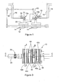
Figure 1 is a diagram illustrating an actuator and rotary control valve arrangement controlling the operation thereof; -
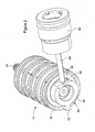
Figure 2 is a perspective view illustrating part of a rotary control valve used in the arrangement ofFigure 1 ; -
Figure 3 is a side view of part of the rotary control valve shown inFigure 2 ; -
Figures 4, 5 and 6 are sectional views along the lines A-A, B-B and C-C, respectively, inFigure 3 ; -
Figures 7 and 8 are perspective views of the first and second spools of the rotary control valve; and -
Figures 9a and 9b are perspective views of parts of the sleeve of the rotary control valve. - Referring to the accompanying drawings, a
rotary control valve 10 is illustrated for use in controlling the operation of a hydraulic or so-called fuel-draulic actuator 12. As shown inFigure 1 , a pair ofcontrol valves actuator 12, eachcontrol valve control chambers 14 to apressure line 16 and to areturn line 18. A commondrive linkage arrangement 20 is provided to control the operation of thecontrol valves control valves actuator 12, albeit in a degraded manner due to the damping effect provided by the jammed control valve. - The
control valves - As shown in
Figures 2 to 9 , thecontrol valve 10 comprises a first,inner spool 22 which extends through a bore formed in a second,outer spool 24 such that thesecond spool 24 encircles thefirst spool 22. Thefirst spool 22 includes a region of diameter substantially equal to the diameter of the adjacent part of the bore of thesecond spool 24 such as to form a reasonably good seal therewith. Thefirst spool 22 is provided, at a part thereof which projects from thesecond spool 24, with gear teeth orspline formations 26 to allow the associateddrive arrangement 20 to drive thefirst spool 22 for angular movement. - The
first spool 22 is provided, on its periphery, with a first series ofports 28 in the form of recesses. Theports 28 are axially aligned with a second series ofports 30 formed in thesecond spool 24. Unlike the first series ofports 28, theports 30 take the form of openings extending through thesecond spool 24. As best shown inFigure 5 , four equiangularlyspaced ports 28 are provided on thefirst spool 22, and eight equiangularlyspaced ports 30 are provided on thesecond spool 24. The design and positioning of theports first spool 22 occupies a closed position, eachport 28 thereof communicates with just one of theports 30. Angular movement of thefirst spool 22 in either direction away from the closed position results in eachport 28 registering with a pair of adjacent ones of theports 30, establishing communication therebetween. - The
second spool 24 extends through a central passage formed in asleeve 32. Thesleeve 32 is, for convenience, of two part construction, comprising aninner sleeve 34 and anouter sleeve 36. The inner andouter sleeves - The
inner sleeve 34 defines a series ofports 38 which are axially aligned with theports ports 30. It will be appreciated, therefore, that when thesecond spool 24 occupies the angular position illustrated, angular movement of thefirst spool 22 controls communication between adjacent ones of theports 38 provided in theinner sleeve 34. - As shown in
Figure 9a , theports 38 extend through theinner sleeve 34. The outer periphery of theinner sleeve 34 is provided with a series of axially extendingchannels 40 communicating with respective ones of theports 38. Theouter sleeve 36, as shown inFigure 9b , is formed on its outer surface with a series of annular recesses orchambers 42, and eachchamber respective passages 44 formed in the outer sleeve 36 (twopassages 44 in eachchamber channels 40, and hence with a pair of theports 38. In use, thesleeve 32 is located within a housing (not shown) provided with connections such that a first one of thechambers 42a is connected to thehigh pressure line 16, a second one of thechambers 42b is connected to thereturn line 18, a third one of thechambers 42c is connected to afirst control line 50 connected to one of thecontrol chambers 14 of theactuator 12, and a fourth one of thechambers 42d is connected to asecond control line 52 connected to another of thecontrol chambers 14. - It will be appreciated that with the
spools control chambers 14 are made. Theactuator 12 is thus held against movement. From this position, angular movement of thefirst spool 22 in one direction establishes communication between thefirst chamber 42a and thethird chamber 42c, applying high pressure to thefirst control line 50 and associatedcontrol chamber 14, and establishes communication between thesecond chamber 42b and thefourth chamber 42d, connecting thesecond control line 52 and theassociated control chamber 14 to thereturn line 18. Movement of theactuator 12 will thus take place, such movement continuing until either theactuator 12 reaches the end of its travel or the control valve is moved to another position. It will be appreciated that movement of thefirst spool 22 in the opposite direction reverses the connections and so drives theactuator 12 in the opposite direction. - During this mode of operation it is important to ensure that the
second spool 24 does not move relative to thesleeve 32 in order to ensure that the communication between theports 30 of thesecond spool 24 and theports 38 of thesleeve 32 is maintained. In order to resist angular movement of the second spool 24 a latch means 56 is provided. The latch means 56 comprises aflange 58 formed on thesecond spool 24 and provided with arecess 60. As shown inFigure 2 , alatch member 62 in the form of a ball element carried by an end of apiston rod 64 is seated in therecess 60. Thepiston rod 64 is biased by aspring 63 to urge thelatch member 62 into therecess 60. Provided the torque applied to thesecond spool 24, in use, is relatively low, the spring loading applied to thelatch member 62, in combination with the shape of the side walls of therecess 60, is sufficient to hold thesecond spool 24 against angular movement. - In use, if the first and
second spools first spool 22 to drive it to a desired angular position will result in a significant torque loading being applied to thesecond spool 24. If this applied torque is sufficiently large, angular movement of thesecond spool 24 may commence driving thesecond spool 24 towards a by-pass position, thelatch member 62 riding up the ramped side walls of therecess 60 against the action of the applied spring loading to achieve such movement. - As shown in
Figures 6 and 8 , at an axial position spaced from the first and second series ofports second spool 24 is provided with a third series ofports 66 in the form of recesses provided in the periphery thereof. As shown inFigure 4 , foursuch ports 66 are provided. Theports 66 are axially aligned with a fourth series ofports 68 provided in thesleeve 32. Theports 68 are equiangularly spaced, and eight such ports are provided. Alternate ones of theports 68 communicate with thechannels 40 connected to thechamber 42b, and so are connected to thereturn line 18. Two opposing ones of theports 68 communicate with thechannels 40 connected to thechamber 42c and so are connected to thefirst control line 50. The remaining twoports 68 are connected to thechannels 40 communicating with thechamber 42d and so are connected to thesecond control line 52. - When the
second spool 24 is in the angular position illustrated, in which it is latched by the latch means 56, it will be appreciated that eachport 66 of the third series communicates with just one of theports 68 of the fourth series. None of theports 68 communicates via theports 66 with another of theports 68. During normal operation of thecontrol valve 10, therefore, theseports control valve 10 play no part in the operation of thecontrol valve 10 and so have no effect upon the control or operation of theactuator 12. However, in the event that the first andsecond spools second spool 24 is driven for movement, as outlined hereinbefore, after movement of thesecond spool 24 beyond a predetermined distance, eachport 66 will move into communication with two adjacent ones of theports 68. Consequently, communication will be established between both of thecontrol lines return line 18. Depending upon the angular position of thefirst spool 22 relative to thesecond spool 24, one or other of thecontrol lines high pressure line 16, and so some parasitic losses of fuel from thehigh pressure line 16 to thereturn line 18 may take place. - It will be appreciated that by connecting both of the
control lines return line 18, movement of theactuator 12 under the control of, for example, thecontrol valve 10b in the event of a jam within thecontrol valve 10a, may take place without the formation of a hydraulic lock that would otherwise prevent such operation. The failed control valve will damp such movement, but will not prevent it from taking place. Clearly, such damped operation may result in the actuator operating in a degraded condition. However, since the actuator can continue to function, safety is maintained. - As shown in
Figure 1 , conveniently atest piston 70 is associated with eachcontrol valve 10 and is operable to engage aprojection 72 formed on thesecond spool 24 to force thesecond spool 24 out of its normal operating position and thereby mimic the occurrence of a jam. By appropriate control over thepistons 70, testing of the system and its ability to drive theactuator 12 in the event of a failure can take place. For example, by operation of one of thepistons 70, one of thecontrol valves 10 can be temporarily taken out of service to ensure that the actuator can be driven via the other control valve. After testing of one control valve in this manner, the other control valve can be taken out of service to permit completion of the testing operation. - As described hereinbefore, it will be appreciated that the control valve of the invention is advantageous in that it permits the required degree of redundancy to be provided in a relatively simple and convenient manner, without requiring the provision of additional components. It is relatively compact and so easy to accommodate and adds minimal additional weight. A number of other benefits will be appreciated by a man skilled in the art.
- Whilst the description hereinbefore is of one specific embodiment of the invention, it will be appreciated that numerous modifications and alterations may be made without departing from the scope of the invention.
Claims (8)
- A rotary control valve comprising a first spool (22), a second spool (24) encircling at least part of the first spool (22) and angularly moveable relative thereto, and a sleeve (32) encircling at least part of the second spool (24), the second spool (24) being angularly moveable relative to the sleeve (32), the first and second spools (22, 24) having first and second series of ports (28, 30) registrable with one another, depending upon the relative angular positions of the first and second spools (22, 24), to control communication between at least a pressure line (16), a return line (18) and a control line (50, 52) provided in or connected to the sleeve (32), the second spool (24) and the sleeve (32) having third and fourth series of ports (66, 68), axially spaced from the first and second series of ports (28, 30) and registrable with one another, depending upon the relative angular positions of the second spool (24) and the sleeve (32), to control communication between at least the control line (50, 52) and the return line (18), and latch means (56) operable to resist movement of the second spool (24) relative to the sleeve (32).
- A valve according to Claim 1, wherein the latch means (56) comprises a formation provided on the second spool (24), the formation including a recess (60), a latch element (62) cooperating with the formation and being urged into the recess (60) to resist angular movement of the second spool (24).
- A valve according to Claim 2, wherein the latch element (62) is spring biased towards the recess (60).
- A valve according to Claim 2 or Claim 3, wherein the recess (60) is of symmetrical, ramped form.
- A valve according to any of the preceding claims, wherein first and second control lines (50, 52) are provided, the establishment of communication between the ports of the first and second series of ports (28, 30) providing communication between one of the control lines (50, 52) and the pressure line (16) and providing communication between the other of the control lines (50, 52) and the return line (18).
- A valve according to Claim 5, wherein the establishment of communication between the ports of the third and fourth series of ports (66, 68) connects both the first control line (50) and the second control line (52) to the return line (18).
- An actuator control arrangement comprising a pair of control valves (10a, 10b) as claimed in any of the preceding claims and used in combination in controlling the operation of an actuator (12).
- An arrangement according to Claim 7, wherein the control valves (10a, 10b) are driven synchronously and, in the event of a jam within one of the valves (10a, 10b), the jammed control valve (10a, 10b) occupies its by-pass position at any time that the still functioning valve (10a, 10b) establishes communication between the control line(s) (50, 52) and the pressure line (16) and/or return line (18).
Priority Applications (1)
| Application Number | Priority Date | Filing Date | Title |
|---|---|---|---|
| EP14199298.2A EP2863069B1 (en) | 2011-09-28 | 2012-09-12 | Rotary control valve |
Applications Claiming Priority (1)
| Application Number | Priority Date | Filing Date | Title |
|---|---|---|---|
| GB201116679A GB201116679D0 (en) | 2011-09-28 | 2011-09-28 | Rotary control valve |
Related Child Applications (2)
| Application Number | Title | Priority Date | Filing Date |
|---|---|---|---|
| EP14199298.2A Division-Into EP2863069B1 (en) | 2011-09-28 | 2012-09-12 | Rotary control valve |
| EP14199298.2A Division EP2863069B1 (en) | 2011-09-28 | 2012-09-12 | Rotary control valve |
Publications (3)
| Publication Number | Publication Date |
|---|---|
| EP2574797A2 true EP2574797A2 (en) | 2013-04-03 |
| EP2574797A3 EP2574797A3 (en) | 2013-10-16 |
| EP2574797B1 EP2574797B1 (en) | 2015-06-10 |
Family
ID=44994083
Family Applications (2)
| Application Number | Title | Priority Date | Filing Date |
|---|---|---|---|
| EP12184132.4A Active EP2574797B1 (en) | 2011-09-28 | 2012-09-12 | Rotary control valve |
| EP14199298.2A Active EP2863069B1 (en) | 2011-09-28 | 2012-09-12 | Rotary control valve |
Family Applications After (1)
| Application Number | Title | Priority Date | Filing Date |
|---|---|---|---|
| EP14199298.2A Active EP2863069B1 (en) | 2011-09-28 | 2012-09-12 | Rotary control valve |
Country Status (4)
| Country | Link |
|---|---|
| US (1) | US8960228B2 (en) |
| EP (2) | EP2574797B1 (en) |
| GB (1) | GB201116679D0 (en) |
| RU (1) | RU2610969C2 (en) |
Cited By (2)
| Publication number | Priority date | Publication date | Assignee | Title |
|---|---|---|---|---|
| EP2913265A1 (en) * | 2014-02-27 | 2015-09-02 | Goodrich Actuation Systems SAS | Stability and control augmentation system |
| EP3309063A1 (en) | 2016-10-14 | 2018-04-18 | Goodrich Actuation Systems SAS | Actuator control arrangement |
Families Citing this family (9)
| Publication number | Priority date | Publication date | Assignee | Title |
|---|---|---|---|---|
| US9435446B1 (en) * | 2014-07-24 | 2016-09-06 | Google Inc. | Rotary valve with brake mode |
| US9493932B2 (en) | 2014-10-06 | 2016-11-15 | International Business Machines Corporation | Configurable modular sleeve valve |
| CA2964150C (en) * | 2014-10-09 | 2022-03-01 | National Machine Company | Nose wheel steering valve |
| GB2522744B (en) * | 2014-11-14 | 2016-03-16 | Blagdon Actuation Res Ltd | Servo actuators |
| US10864786B2 (en) * | 2017-11-03 | 2020-12-15 | Milton Industries, P.C. | Highflow air coupling device and system |
| FR3077753B1 (en) * | 2018-02-14 | 2020-01-31 | Montabert | METHOD FOR ADJUSTING THE STRIKING STROKE OF A STRIKING PISTON OF A PERCUSSION APPARATUS, AND A PERCUSSION APPARATUS FOR CARRYING OUT SAID METHOD |
| US11168578B2 (en) * | 2018-09-11 | 2021-11-09 | Pratt & Whitney Canada Corp. | System for adjusting a variable position vane in an aircraft engine |
| KR102842802B1 (en) * | 2020-09-09 | 2025-08-05 | 현대자동차 주식회사 | Multiway coolant valve |
| WO2022144862A1 (en) * | 2021-01-04 | 2022-07-07 | Mohammad Durali | Hydraulic directional control valve |
Family Cites Families (9)
| Publication number | Priority date | Publication date | Assignee | Title |
|---|---|---|---|---|
| US2675679A (en) * | 1954-04-20 | Hydraulic motor and emergency | ||
| US1084740A (en) * | 1912-12-30 | 1914-01-20 | Hans Holzwarth | Apparatus for actuating and governing parts of gas-turbines and other motive-power devices |
| USRE25126E (en) * | 1958-11-25 | 1962-02-20 | Controller for fluid pressure operated devices | |
| US4040338A (en) * | 1976-06-14 | 1977-08-09 | Logansport Machine Co., Inc. | Fluid supply distributor |
| JPS5522572A (en) * | 1978-08-07 | 1980-02-18 | Nissan Motor Co Ltd | Rotary valve |
| FR2460435A1 (en) * | 1979-07-03 | 1981-01-23 | Applic Mach Motrices | HYDRAULIC DISPENSER, IN PARTICULAR FOR EQUIPPING AIRCRAFT AND HELICOPTER SERVO CONTROLS |
| SU945547A1 (en) * | 1980-12-30 | 1982-07-23 | Всесоюзный Научно-Исследовательский И Проектно-Конструкторский Институт Атомного Энергетического Машиностроения | Regulating valve |
| FR2610072B1 (en) * | 1987-01-22 | 1989-05-19 | Applic Mach Motrices | ELECTROHYDRAULIC SERVOVALVE FOR THE CONTROLLED CONTROL OF A HYDRAULIC ACTUATOR, PARTICULARLY IN AIRCRAFT FLIGHT CONTROL SERVOMECHANISMS |
| US8578967B2 (en) | 2009-01-29 | 2013-11-12 | Pratt & Whitney Canada Corp. | Pressure regulating valve for aircraft engine |
-
2011
- 2011-09-28 GB GB201116679A patent/GB201116679D0/en not_active Ceased
-
2012
- 2012-09-12 EP EP12184132.4A patent/EP2574797B1/en active Active
- 2012-09-12 EP EP14199298.2A patent/EP2863069B1/en active Active
- 2012-09-14 US US13/617,199 patent/US8960228B2/en active Active
- 2012-09-27 RU RU2012141302A patent/RU2610969C2/en active
Non-Patent Citations (1)
| Title |
|---|
| None |
Cited By (4)
| Publication number | Priority date | Publication date | Assignee | Title |
|---|---|---|---|---|
| EP2913265A1 (en) * | 2014-02-27 | 2015-09-02 | Goodrich Actuation Systems SAS | Stability and control augmentation system |
| US10037040B2 (en) | 2014-02-27 | 2018-07-31 | Goodrich Actuation Systems Sas | Stability and control augmentation system |
| EP3309063A1 (en) | 2016-10-14 | 2018-04-18 | Goodrich Actuation Systems SAS | Actuator control arrangement |
| US10502244B2 (en) | 2016-10-14 | 2019-12-10 | Goodrich Actuation Systems Sas | Actuator control arrangement |
Also Published As
| Publication number | Publication date |
|---|---|
| EP2574797B1 (en) | 2015-06-10 |
| EP2863069A1 (en) | 2015-04-22 |
| RU2610969C2 (en) | 2017-02-17 |
| RU2012141302A (en) | 2014-04-10 |
| GB201116679D0 (en) | 2011-11-09 |
| US20130075642A1 (en) | 2013-03-28 |
| US8960228B2 (en) | 2015-02-24 |
| EP2863069B1 (en) | 2017-12-13 |
| EP2574797A3 (en) | 2013-10-16 |
Similar Documents
| Publication | Publication Date | Title |
|---|---|---|
| EP2574797B1 (en) | Rotary control valve | |
| US9027597B2 (en) | Operating device | |
| JP6659476B2 (en) | Electrohydrostatic actuator and method of controlling and damping hydraulic actuator | |
| EP3631235B1 (en) | Electronically controlled valve for a shock absorber | |
| EP4019786B1 (en) | Load-sensing multi-way valve work section | |
| CN103649476B (en) | Valve opening/closing timing control device and valve opening/closing timing control mechanism | |
| EP3553324B1 (en) | Valve and hydraulic system with the same | |
| JP3691197B2 (en) | Hydraulic drive device and direction switching valve device for hydraulic machine | |
| JP7116584B2 (en) | valve device | |
| WO2016098549A1 (en) | Rotary valve and fluidic actuator unit with same | |
| US10502244B2 (en) | Actuator control arrangement | |
| US10982692B2 (en) | Swing-back preventing apparatus | |
| WO2012070392A1 (en) | Hydraulic cylinder system | |
| EP3669096B1 (en) | Control systems for hydraulic axial displacement machines | |
| EP2843200B1 (en) | Control valve | |
| CN114688118A (en) | Load-sensitive multi-way valve reversing linkage | |
| CN214577994U (en) | Load-sensitive multi-way valve reversing linkage | |
| JP4429659B2 (en) | Switching valve | |
| JP6966961B2 (en) | Control valve | |
| US20260126060A1 (en) | Transfer valve with dual authority control porting | |
| JP2010540855A (en) | Device for damping torsional vibration of hollow drive shaft | |
| JP7147679B2 (en) | pilot lock valve | |
| JP2675128B2 (en) | Full hydraulic steering system | |
| JP2008039020A (en) | Hydraulic motor drive device | |
| JP2005170131A (en) | Actuator unit |
Legal Events
| Date | Code | Title | Description |
|---|---|---|---|
| PUAI | Public reference made under article 153(3) epc to a published international application that has entered the european phase |
Free format text: ORIGINAL CODE: 0009012 |
|
| AK | Designated contracting states |
Kind code of ref document: A2 Designated state(s): AL AT BE BG CH CY CZ DE DK EE ES FI FR GB GR HR HU IE IS IT LI LT LU LV MC MK MT NL NO PL PT RO RS SE SI SK SM TR |
|
| AX | Request for extension of the european patent |
Extension state: BA ME |
|
| PUAL | Search report despatched |
Free format text: ORIGINAL CODE: 0009013 |
|
| AK | Designated contracting states |
Kind code of ref document: A3 Designated state(s): AL AT BE BG CH CY CZ DE DK EE ES FI FR GB GR HR HU IE IS IT LI LT LU LV MC MK MT NL NO PL PT RO RS SE SI SK SM TR |
|
| AX | Request for extension of the european patent |
Extension state: BA ME |
|
| RIC1 | Information provided on ipc code assigned before grant |
Ipc: F15B 13/04 20060101AFI20130909BHEP Ipc: F15B 20/00 20060101ALI20130909BHEP |
|
| 17P | Request for examination filed |
Effective date: 20140416 |
|
| RBV | Designated contracting states (corrected) |
Designated state(s): AL AT BE BG CH CY CZ DE DK EE ES FI FR GB GR HR HU IE IS IT LI LT LU LV MC MK MT NL NO PL PT RO RS SE SI SK SM TR |
|
| GRAP | Despatch of communication of intention to grant a patent |
Free format text: ORIGINAL CODE: EPIDOSNIGR1 |
|
| INTG | Intention to grant announced |
Effective date: 20141223 |
|
| GRAS | Grant fee paid |
Free format text: ORIGINAL CODE: EPIDOSNIGR3 |
|
| GRAA | (expected) grant |
Free format text: ORIGINAL CODE: 0009210 |
|
| AK | Designated contracting states |
Kind code of ref document: B1 Designated state(s): AL AT BE BG CH CY CZ DE DK EE ES FI FR GB GR HR HU IE IS IT LI LT LU LV MC MK MT NL NO PL PT RO RS SE SI SK SM TR |
|
| REG | Reference to a national code |
Ref country code: GB Ref legal event code: FG4D |
|
| REG | Reference to a national code |
Ref country code: CH Ref legal event code: EP |
|
| REG | Reference to a national code |
Ref country code: AT Ref legal event code: REF Ref document number: 731033 Country of ref document: AT Kind code of ref document: T Effective date: 20150715 |
|
| REG | Reference to a national code |
Ref country code: DE Ref legal event code: R096 Ref document number: 602012007853 Country of ref document: DE |
|
| REG | Reference to a national code |
Ref country code: IE Ref legal event code: FG4D |
|
| PG25 | Lapsed in a contracting state [announced via postgrant information from national office to epo] |
Ref country code: LT Free format text: LAPSE BECAUSE OF FAILURE TO SUBMIT A TRANSLATION OF THE DESCRIPTION OR TO PAY THE FEE WITHIN THE PRESCRIBED TIME-LIMIT Effective date: 20150610 Ref country code: FI Free format text: LAPSE BECAUSE OF FAILURE TO SUBMIT A TRANSLATION OF THE DESCRIPTION OR TO PAY THE FEE WITHIN THE PRESCRIBED TIME-LIMIT Effective date: 20150610 Ref country code: ES Free format text: LAPSE BECAUSE OF FAILURE TO SUBMIT A TRANSLATION OF THE DESCRIPTION OR TO PAY THE FEE WITHIN THE PRESCRIBED TIME-LIMIT Effective date: 20150610 Ref country code: NO Free format text: LAPSE BECAUSE OF FAILURE TO SUBMIT A TRANSLATION OF THE DESCRIPTION OR TO PAY THE FEE WITHIN THE PRESCRIBED TIME-LIMIT Effective date: 20150910 |
|
| REG | Reference to a national code |
Ref country code: AT Ref legal event code: MK05 Ref document number: 731033 Country of ref document: AT Kind code of ref document: T Effective date: 20150610 |
|
| REG | Reference to a national code |
Ref country code: NL Ref legal event code: MP Effective date: 20150610 |
|
| PG25 | Lapsed in a contracting state [announced via postgrant information from national office to epo] |
Ref country code: BG Free format text: LAPSE BECAUSE OF FAILURE TO SUBMIT A TRANSLATION OF THE DESCRIPTION OR TO PAY THE FEE WITHIN THE PRESCRIBED TIME-LIMIT Effective date: 20150910 Ref country code: RS Free format text: LAPSE BECAUSE OF FAILURE TO SUBMIT A TRANSLATION OF THE DESCRIPTION OR TO PAY THE FEE WITHIN THE PRESCRIBED TIME-LIMIT Effective date: 20150610 Ref country code: GR Free format text: LAPSE BECAUSE OF FAILURE TO SUBMIT A TRANSLATION OF THE DESCRIPTION OR TO PAY THE FEE WITHIN THE PRESCRIBED TIME-LIMIT Effective date: 20150911 Ref country code: LV Free format text: LAPSE BECAUSE OF FAILURE TO SUBMIT A TRANSLATION OF THE DESCRIPTION OR TO PAY THE FEE WITHIN THE PRESCRIBED TIME-LIMIT Effective date: 20150610 |
|
| PG25 | Lapsed in a contracting state [announced via postgrant information from national office to epo] |
Ref country code: EE Free format text: LAPSE BECAUSE OF FAILURE TO SUBMIT A TRANSLATION OF THE DESCRIPTION OR TO PAY THE FEE WITHIN THE PRESCRIBED TIME-LIMIT Effective date: 20150610 |
|
| PG25 | Lapsed in a contracting state [announced via postgrant information from national office to epo] |
Ref country code: CZ Free format text: LAPSE BECAUSE OF FAILURE TO SUBMIT A TRANSLATION OF THE DESCRIPTION OR TO PAY THE FEE WITHIN THE PRESCRIBED TIME-LIMIT Effective date: 20150610 Ref country code: IS Free format text: LAPSE BECAUSE OF FAILURE TO SUBMIT A TRANSLATION OF THE DESCRIPTION OR TO PAY THE FEE WITHIN THE PRESCRIBED TIME-LIMIT Effective date: 20151010 Ref country code: PL Free format text: LAPSE BECAUSE OF FAILURE TO SUBMIT A TRANSLATION OF THE DESCRIPTION OR TO PAY THE FEE WITHIN THE PRESCRIBED TIME-LIMIT Effective date: 20150610 Ref country code: AT Free format text: LAPSE BECAUSE OF FAILURE TO SUBMIT A TRANSLATION OF THE DESCRIPTION OR TO PAY THE FEE WITHIN THE PRESCRIBED TIME-LIMIT Effective date: 20150610 Ref country code: SK Free format text: LAPSE BECAUSE OF FAILURE TO SUBMIT A TRANSLATION OF THE DESCRIPTION OR TO PAY THE FEE WITHIN THE PRESCRIBED TIME-LIMIT Effective date: 20150610 Ref country code: RO Free format text: LAPSE BECAUSE OF NON-PAYMENT OF DUE FEES Effective date: 20150610 Ref country code: PT Free format text: LAPSE BECAUSE OF FAILURE TO SUBMIT A TRANSLATION OF THE DESCRIPTION OR TO PAY THE FEE WITHIN THE PRESCRIBED TIME-LIMIT Effective date: 20151012 |
|
| REG | Reference to a national code |
Ref country code: DE Ref legal event code: R097 Ref document number: 602012007853 Country of ref document: DE |
|
| PLBE | No opposition filed within time limit |
Free format text: ORIGINAL CODE: 0009261 |
|
| STAA | Information on the status of an ep patent application or granted ep patent |
Free format text: STATUS: NO OPPOSITION FILED WITHIN TIME LIMIT |
|
| PG25 | Lapsed in a contracting state [announced via postgrant information from national office to epo] |
Ref country code: LU Free format text: LAPSE BECAUSE OF FAILURE TO SUBMIT A TRANSLATION OF THE DESCRIPTION OR TO PAY THE FEE WITHIN THE PRESCRIBED TIME-LIMIT Effective date: 20150912 Ref country code: DK Free format text: LAPSE BECAUSE OF FAILURE TO SUBMIT A TRANSLATION OF THE DESCRIPTION OR TO PAY THE FEE WITHIN THE PRESCRIBED TIME-LIMIT Effective date: 20150610 Ref country code: MC Free format text: LAPSE BECAUSE OF FAILURE TO SUBMIT A TRANSLATION OF THE DESCRIPTION OR TO PAY THE FEE WITHIN THE PRESCRIBED TIME-LIMIT Effective date: 20150610 |
|
| REG | Reference to a national code |
Ref country code: CH Ref legal event code: PL |
|
| 26N | No opposition filed |
Effective date: 20160311 |
|
| PG25 | Lapsed in a contracting state [announced via postgrant information from national office to epo] |
Ref country code: SI Free format text: LAPSE BECAUSE OF FAILURE TO SUBMIT A TRANSLATION OF THE DESCRIPTION OR TO PAY THE FEE WITHIN THE PRESCRIBED TIME-LIMIT Effective date: 20150610 |
|
| REG | Reference to a national code |
Ref country code: IE Ref legal event code: MM4A |
|
| PG25 | Lapsed in a contracting state [announced via postgrant information from national office to epo] |
Ref country code: CH Free format text: LAPSE BECAUSE OF NON-PAYMENT OF DUE FEES Effective date: 20150930 Ref country code: LI Free format text: LAPSE BECAUSE OF NON-PAYMENT OF DUE FEES Effective date: 20150930 Ref country code: IE Free format text: LAPSE BECAUSE OF NON-PAYMENT OF DUE FEES Effective date: 20150912 |
|
| REG | Reference to a national code |
Ref country code: FR Ref legal event code: PLFP Year of fee payment: 5 |
|
| PG25 | Lapsed in a contracting state [announced via postgrant information from national office to epo] |
Ref country code: BE Free format text: LAPSE BECAUSE OF FAILURE TO SUBMIT A TRANSLATION OF THE DESCRIPTION OR TO PAY THE FEE WITHIN THE PRESCRIBED TIME-LIMIT Effective date: 20150610 |
|
| PG25 | Lapsed in a contracting state [announced via postgrant information from national office to epo] |
Ref country code: MT Free format text: LAPSE BECAUSE OF FAILURE TO SUBMIT A TRANSLATION OF THE DESCRIPTION OR TO PAY THE FEE WITHIN THE PRESCRIBED TIME-LIMIT Effective date: 20150610 |
|
| PG25 | Lapsed in a contracting state [announced via postgrant information from national office to epo] |
Ref country code: HU Free format text: LAPSE BECAUSE OF FAILURE TO SUBMIT A TRANSLATION OF THE DESCRIPTION OR TO PAY THE FEE WITHIN THE PRESCRIBED TIME-LIMIT; INVALID AB INITIO Effective date: 20120912 Ref country code: SM Free format text: LAPSE BECAUSE OF FAILURE TO SUBMIT A TRANSLATION OF THE DESCRIPTION OR TO PAY THE FEE WITHIN THE PRESCRIBED TIME-LIMIT Effective date: 20150610 |
|
| PG25 | Lapsed in a contracting state [announced via postgrant information from national office to epo] |
Ref country code: NL Free format text: LAPSE BECAUSE OF FAILURE TO SUBMIT A TRANSLATION OF THE DESCRIPTION OR TO PAY THE FEE WITHIN THE PRESCRIBED TIME-LIMIT Effective date: 20150610 Ref country code: SE Free format text: LAPSE BECAUSE OF FAILURE TO SUBMIT A TRANSLATION OF THE DESCRIPTION OR TO PAY THE FEE WITHIN THE PRESCRIBED TIME-LIMIT Effective date: 20150610 Ref country code: CY Free format text: LAPSE BECAUSE OF FAILURE TO SUBMIT A TRANSLATION OF THE DESCRIPTION OR TO PAY THE FEE WITHIN THE PRESCRIBED TIME-LIMIT Effective date: 20150610 |
|
| PG25 | Lapsed in a contracting state [announced via postgrant information from national office to epo] |
Ref country code: HR Free format text: LAPSE BECAUSE OF FAILURE TO SUBMIT A TRANSLATION OF THE DESCRIPTION OR TO PAY THE FEE WITHIN THE PRESCRIBED TIME-LIMIT Effective date: 20150610 |
|
| REG | Reference to a national code |
Ref country code: FR Ref legal event code: PLFP Year of fee payment: 6 |
|
| PG25 | Lapsed in a contracting state [announced via postgrant information from national office to epo] |
Ref country code: TR Free format text: LAPSE BECAUSE OF FAILURE TO SUBMIT A TRANSLATION OF THE DESCRIPTION OR TO PAY THE FEE WITHIN THE PRESCRIBED TIME-LIMIT Effective date: 20150610 |
|
| PG25 | Lapsed in a contracting state [announced via postgrant information from national office to epo] |
Ref country code: MK Free format text: LAPSE BECAUSE OF FAILURE TO SUBMIT A TRANSLATION OF THE DESCRIPTION OR TO PAY THE FEE WITHIN THE PRESCRIBED TIME-LIMIT Effective date: 20150610 |
|
| REG | Reference to a national code |
Ref country code: FR Ref legal event code: PLFP Year of fee payment: 7 |
|
| PG25 | Lapsed in a contracting state [announced via postgrant information from national office to epo] |
Ref country code: AL Free format text: LAPSE BECAUSE OF FAILURE TO SUBMIT A TRANSLATION OF THE DESCRIPTION OR TO PAY THE FEE WITHIN THE PRESCRIBED TIME-LIMIT Effective date: 20150610 |
|
| REG | Reference to a national code |
Ref country code: DE Ref legal event code: R082 Ref document number: 602012007853 Country of ref document: DE |
|
| PGFP | Annual fee paid to national office [announced via postgrant information from national office to epo] |
Ref country code: DE Payment date: 20250916 Year of fee payment: 14 |
|
| PGFP | Annual fee paid to national office [announced via postgrant information from national office to epo] |
Ref country code: IT Payment date: 20250910 Year of fee payment: 14 |
|
| PGFP | Annual fee paid to national office [announced via postgrant information from national office to epo] |
Ref country code: GB Payment date: 20250919 Year of fee payment: 14 |
|
| PGFP | Annual fee paid to national office [announced via postgrant information from national office to epo] |
Ref country code: FR Payment date: 20250929 Year of fee payment: 14 |