EP2574737A2 - Gas turbine engine tie rod retainer - Google Patents
Gas turbine engine tie rod retainer Download PDFInfo
- Publication number
- EP2574737A2 EP2574737A2 EP12186048A EP12186048A EP2574737A2 EP 2574737 A2 EP2574737 A2 EP 2574737A2 EP 12186048 A EP12186048 A EP 12186048A EP 12186048 A EP12186048 A EP 12186048A EP 2574737 A2 EP2574737 A2 EP 2574737A2
- Authority
- EP
- European Patent Office
- Prior art keywords
- assembly
- tie rod
- base
- counterbore
- shaft
- Prior art date
- Legal status (The legal status is an assumption and is not a legal conclusion. Google has not performed a legal analysis and makes no representation as to the accuracy of the status listed.)
- Granted
Links
Images



Classifications
-
- F—MECHANICAL ENGINEERING; LIGHTING; HEATING; WEAPONS; BLASTING
- F01—MACHINES OR ENGINES IN GENERAL; ENGINE PLANTS IN GENERAL; STEAM ENGINES
- F01D—NON-POSITIVE DISPLACEMENT MACHINES OR ENGINES, e.g. STEAM TURBINES
- F01D25/00—Component parts, details, or accessories, not provided for in, or of interest apart from, other groups
- F01D25/16—Arrangement of bearings; Supporting or mounting bearings in casings
- F01D25/162—Bearing supports
-
- F—MECHANICAL ENGINEERING; LIGHTING; HEATING; WEAPONS; BLASTING
- F01—MACHINES OR ENGINES IN GENERAL; ENGINE PLANTS IN GENERAL; STEAM ENGINES
- F01D—NON-POSITIVE DISPLACEMENT MACHINES OR ENGINES, e.g. STEAM TURBINES
- F01D5/00—Blades; Blade-carrying members; Heating, heat-insulating, cooling or antivibration means on the blades or the members
- F01D5/02—Blade-carrying members, e.g. rotors
- F01D5/06—Rotors for more than one axial stage, e.g. of drum or multiple disc type; Details thereof, e.g. shafts, shaft connections
- F01D5/066—Connecting means for joining rotor-discs or rotor-elements together, e.g. by a central bolt, by clamps
-
- F—MECHANICAL ENGINEERING; LIGHTING; HEATING; WEAPONS; BLASTING
- F05—INDEXING SCHEMES RELATING TO ENGINES OR PUMPS IN VARIOUS SUBCLASSES OF CLASSES F01-F04
- F05D—INDEXING SCHEME FOR ASPECTS RELATING TO NON-POSITIVE-DISPLACEMENT MACHINES OR ENGINES, GAS-TURBINES OR JET-PROPULSION PLANTS
- F05D2250/00—Geometry
- F05D2250/20—Three-dimensional
- F05D2250/28—Three-dimensional patterned
- F05D2250/281—Three-dimensional patterned threaded
-
- F—MECHANICAL ENGINEERING; LIGHTING; HEATING; WEAPONS; BLASTING
- F05—INDEXING SCHEMES RELATING TO ENGINES OR PUMPS IN VARIOUS SUBCLASSES OF CLASSES F01-F04
- F05D—INDEXING SCHEME FOR ASPECTS RELATING TO NON-POSITIVE-DISPLACEMENT MACHINES OR ENGINES, GAS-TURBINES OR JET-PROPULSION PLANTS
- F05D2250/00—Geometry
- F05D2250/30—Arrangement of components
- F05D2250/31—Arrangement of components according to the direction of their main axis or their axis of rotation
- F05D2250/311—Arrangement of components according to the direction of their main axis or their axis of rotation the axes being in line
-
- F—MECHANICAL ENGINEERING; LIGHTING; HEATING; WEAPONS; BLASTING
- F05—INDEXING SCHEMES RELATING TO ENGINES OR PUMPS IN VARIOUS SUBCLASSES OF CLASSES F01-F04
- F05D—INDEXING SCHEME FOR ASPECTS RELATING TO NON-POSITIVE-DISPLACEMENT MACHINES OR ENGINES, GAS-TURBINES OR JET-PROPULSION PLANTS
- F05D2250/00—Geometry
- F05D2250/30—Arrangement of components
- F05D2250/31—Arrangement of components according to the direction of their main axis or their axis of rotation
- F05D2250/312—Arrangement of components according to the direction of their main axis or their axis of rotation the axes being parallel to each other
-
- F—MECHANICAL ENGINEERING; LIGHTING; HEATING; WEAPONS; BLASTING
- F05—INDEXING SCHEMES RELATING TO ENGINES OR PUMPS IN VARIOUS SUBCLASSES OF CLASSES F01-F04
- F05D—INDEXING SCHEME FOR ASPECTS RELATING TO NON-POSITIVE-DISPLACEMENT MACHINES OR ENGINES, GAS-TURBINES OR JET-PROPULSION PLANTS
- F05D2260/00—Function
- F05D2260/30—Retaining components in desired mutual position
- F05D2260/31—Retaining bolts or nuts
-
- Y—GENERAL TAGGING OF NEW TECHNOLOGICAL DEVELOPMENTS; GENERAL TAGGING OF CROSS-SECTIONAL TECHNOLOGIES SPANNING OVER SEVERAL SECTIONS OF THE IPC; TECHNICAL SUBJECTS COVERED BY FORMER USPC CROSS-REFERENCE ART COLLECTIONS [XRACs] AND DIGESTS
- Y10—TECHNICAL SUBJECTS COVERED BY FORMER USPC
- Y10T—TECHNICAL SUBJECTS COVERED BY FORMER US CLASSIFICATION
- Y10T403/00—Joints and connections
- Y10T403/33—Transverse rod to spaced plate surfaces
- Y10T403/335—Retainer utilizes or abuts plural plates
Definitions
- the present invention relates generally to a gas turbine engine and, more particularly, to a rod assembly attaching a bearing assembly to an outer casing.
- a gas turbine engine of the turbofan type generally includes, from forward to aft a forward fan, a low pressure compressor, a higher pressure compressor, a burner, a high pressure turbine, and an aft low pressure power turbine.
- the higher pressure compressor and high pressure turbine of the core engine are connected by a first shaft.
- the low pressure turbine and the fan are connected by a second shaft that rotates with the first shaft that connects the high pressure turbine and the higher pressure compressor.
- An engine frame may be used to support the bearings of the engine's turbines.
- Bearing support frames may be heavy.
- the frames may also be subject to thermal stresses, thermal gradients and may require heat shields if subjected to hot flow path gases.
- Other prior art supports use an inner ring structure mounting to an inner annular bearing.
- the ring structure attaches to a plurality of tie rods that attach to the inner annular ring, an intermediate support structure and an engine casing.
- an assembly for use with a gas turbine engine includes a tie rod and a connector.
- the tie rod which is for extending radially outwardly from a latitudinal axis of the gas turbine engine, has a hollow length having a longitudinal axis and a base having a width in parallel to the latitudinal axis.
- the base has a counterbore disposed therein and is wider than a width of the length.
- the connector for attaching the base of the tie rod to a bearing assembly of the gas turbine engine, has a hollow body having a shaft removably attaching, at a first end portion thereof, to the counterbore.
- the shaft and the counterbore are disposed in parallel with the longitudinal axis.
- an assembly for use with a gas turbine engine includes a bearing assembly, a tie rod, and a connector.
- the tie rod which is for extending radially outwardly from bearing assembly along a longitudinal axis, has a hollow length extending along the longitudinal axis and a base having a width normal to the longitudinal axis.
- the base has a counterbore disposed therein and the base is wider than a width of the length.
- the connector which attaches the base of the tie rod to the bearing assembly, has a hollow body having a shaft removably attaching, at a first end portion thereof, to the counterbore.
- the shaft and the counterbore are disposed in parallel with the longitudinal axis.
- a gas turbine engine 10 has a casing 15 surrounding a high pressure turbine 20, a low pressure turbine 25 aft of the high pressure turbine 20, and a medium frame 30 disposed there between.
- a duct 35 transmits high temperature and pressure gases from the high pressure turbine 20 to the low pressure turbine 25 through the medium turbine frame 30.
- the high pressure turbine 20 connects to a HPT shaft 40 that rotates about a latitudinal axis 43.
- the HPT shaft 40 is rotatably supported by a HPT bearing assembly 45.
- the low pressure turbine 25 connects to an LPT shaft 50 that rotates coaxially within the HPT shaft 40.
- the LPT shaft 50 is rotatably supported by a LPT bearing assembly 55.
- a plurality of tie rods 60 are disposed radially about the axis 43 and extend through the conduit duct 35 to attach to the casing 15.
- Each tie rod 60 has a hexagonally shaped body 65 extending along a longitudinal axis 70. Cooling passageways 75 extend along the axis 70 within the hexagonally shaped body 65 of each tie rod 60.
- Each tie rod 60 has an upper portion 80 attaching conventionally to the casing 15, and a lower portion 85 having a base 90 that is wider than a length of the tie rod, a narrowed portion 95 disposed radially inward of the base 90, and a threaded portion 100 disposed radially inwardly along axis 70 from the narrowed portion 95 that is connected to the HPT bearing assembly 45 by a nut 105.
- An example tie rod has a length of about 16 centimeters.
- a mounting plate 110 on the HPT bearing assembly 45 has a top surface 115, a hexagonal depression 120 receiving the lower portion 85 of the tie rod 60, an opening for receiving the narrowed portion 95 of the tie rod 60, axially disposed ears 130 that are connected by bolts 135 to the bearing casing 140.
- a bending moment 143 caused by a reaction between the HPT bearing assembly 45 (and other engine parts and assemblies) and the casing 15 to the propulsive action of the highly energized gas passing from a burner (not shown), may cause a tie rod 60 to wear prematurely.
- the bending moment 143 on the tie rod 60 may force a forward side 150 of the base 90 downwardly into contact with the mounting plate top surface 115 and cause the aft portion 145 to move upwardly away from the top surface 115.
- This bending or tilting motion may cause higher stresses on a fillet 155, causing premature wear.
- a prior art base has a width along the axis 43 of about 3 cm.
- a tie rod 60 has a widened base 200 that is 30 percent wider than base 290 (see Fig. 3 ), and a counterbore 205 that is concentric with cooling passageway 75 and axis 70.
- the counterbore 205 has threads 210 disposed therein for receiving bolt 215.
- the bolt 215 has a retaining wrenching head 220, a narrowed neck 225 fitting within the opening 125 in the mounting plate 110, a cooling passageway 230 extending through the bolt along axis 70, and threads 235 that cooperate with threads 210 within the counterbore.
- the widened base 200 resists the bending moment thereby minimizing the tendency of the aft side 145 of the base 220 from lifting off the top surface 115 and minimizing stresses. Moreover, the fillet 155 in the bolt 60 of the prior art is eliminated.
- the bolt 215 has a fillet 240 between the torque wrenching head 220 and the neck 225 and pretensioning the bolt 215 minimizes stresses thereupon.
- the widened base 200 has a width along the axis 43 of about 3.9 cm wherein a ratio of the width to a length of the tie rod 60 is .20:1 or greater.
- the widened base 200, disposed in parallel to axis 43, is bisected by the longitudinal axis 70.
- a nipple 241 is provided with nut bolt threads 245, instead of a torque wrenching head 250, to secure the nipple behind the mounting plate 110.
- the threads 210 in the counterbore do not extend to a bottom 251 of the tie rods thereby creating an offset 247 in the counterbore to allow for stretch of the bolt nipple 241. Such stretch helps minimize the bending moment on the tie rod 60.
- the nipple 241 is screwed into the counter bore 205 place through the mounting plate 110 and secured by nut 250.
- the base 300 of the tie rod 60 is widened about 40% percent bigger than the widened base 290 (see Fig. 3 ), and has a thickened, eccentric portion 305 extending forward along axis 43 in opposition to the bending moment 143 causing the base 300 to form an eccentrically shape.
- the counterbore 310 is offset from the cooling passageway 75 and axis 70 towards the aft side 145.
- the counterbore has threads 311 therewithin.
- a bolt 315 has a retained wrench head 320, a narrowed neck 325 inserted in opening 125, and bolt threads 330 cooperating with threads 311 to anchor the bolt 315 within the counterbore 310.
- the widened base 200 has a width along the axis 43 of about 4.2 cm wherein a ratio of the width to length of the tie rod 60 is .25:1 or greater.
- the widened base 300, disposed in parallel to axis 43, is not bisected by the longitudinal axis 70 because the thickened portion 305 is wider than the other side 307 of the base 300.
Landscapes
- Engineering & Computer Science (AREA)
- Mechanical Engineering (AREA)
- General Engineering & Computer Science (AREA)
- Turbine Rotor Nozzle Sealing (AREA)
- Mounting Of Bearings Or Others (AREA)
Abstract
Description
- The present invention relates generally to a gas turbine engine and, more particularly, to a rod assembly attaching a bearing assembly to an outer casing.
- A gas turbine engine of the turbofan type generally includes, from forward to aft a forward fan, a low pressure compressor, a higher pressure compressor, a burner, a high pressure turbine, and an aft low pressure power turbine. The higher pressure compressor and high pressure turbine of the core engine are connected by a first shaft. The low pressure turbine and the fan are connected by a second shaft that rotates with the first shaft that connects the high pressure turbine and the higher pressure compressor. Air passes through the fan, is compressed by the low pressure turbine, is compressed further by the higher pressure turbine, and is mixed with fuel and ignited in the burner. After ignition, the highly energized gas stream expands thereby, in sequence rotating the high pressure turbine to rotate the higher pressure compressor, rotating the low pressure turbine to rotate the fan, and exhausting from the engine.
- In a turbofan engine, some thrust is produced by the highly energized gas stream exiting the engine, most of the thrust produced is generated by the forward fan. In a turbojet engine, in contrast, much of an engine thrust is produced by the exiting of the highly energized gas stream.
- An engine frame may be used to support the bearings of the engine's turbines. Bearing support frames, however, may be heavy. The frames may also be subject to thermal stresses, thermal gradients and may require heat shields if subjected to hot flow path gases. Other prior art supports use an inner ring structure mounting to an inner annular bearing. The ring structure attaches to a plurality of tie rods that attach to the inner annular ring, an intermediate support structure and an engine casing.
- According to an embodiment disclosed herein, an assembly for use with a gas turbine engine includes a tie rod and a connector. The tie rod, which is for extending radially outwardly from a latitudinal axis of the gas turbine engine, has a hollow length having a longitudinal axis and a base having a width in parallel to the latitudinal axis. The base has a counterbore disposed therein and is wider than a width of the length. The connector, for attaching the base of the tie rod to a bearing assembly of the gas turbine engine, has a hollow body having a shaft removably attaching, at a first end portion thereof, to the counterbore. The shaft and the counterbore are disposed in parallel with the longitudinal axis.
- According to a further embodiment disclosed herein, an assembly for use with a gas turbine engine includes a bearing assembly, a tie rod, and a connector. The tie rod, which is for extending radially outwardly from bearing assembly along a longitudinal axis, has a hollow length extending along the longitudinal axis and a base having a width normal to the longitudinal axis. The base has a counterbore disposed therein and the base is wider than a width of the length. The connector, which attaches the base of the tie rod to the bearing assembly, has a hollow body having a shaft removably attaching, at a first end portion thereof, to the counterbore. The shaft and the counterbore are disposed in parallel with the longitudinal axis.
-
-
Figure 1 shows a schematic view of a portion of a gas turbine engine having a prior art tie rod attaching a bearing to an engine casing. -
Figure 2 shows a schematic view of a prior art tie rod attaching a bearing to an engine casing, taken along the lines 2-2 ofFigure 1 . -
Figure 3 shows a schematic view of a prior art tie rod attaching a bearing to an engine casing, taken along the lines 3-3 ofFigure 2 . -
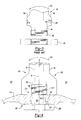
Figure 4 shows a schematic view of a first embodiment of a bottom area of a tie rod attaching to a bearing assembly. -
Figure 5 shows a schematic view of a second embodiment of a bottom area of a tie rod attaching to a bearing assembly. -
Figure 6 shows a schematic view of a third embodiment of a bottom area of a tie rod attaching to a bearing assembly. - Referring now to
Figures 1 and2 , agas turbine engine 10 has acasing 15 surrounding ahigh pressure turbine 20, alow pressure turbine 25 aft of thehigh pressure turbine 20, and amedium frame 30 disposed there between. Aduct 35 transmits high temperature and pressure gases from thehigh pressure turbine 20 to thelow pressure turbine 25 through themedium turbine frame 30. Thehigh pressure turbine 20 connects to aHPT shaft 40 that rotates about alatitudinal axis 43. TheHPT shaft 40 is rotatably supported by aHPT bearing assembly 45. Thelow pressure turbine 25 connects to anLPT shaft 50 that rotates coaxially within theHPT shaft 40. TheLPT shaft 50 is rotatably supported by aLPT bearing assembly 55. - A plurality of
tie rods 60 are disposed radially about theaxis 43 and extend through theconduit duct 35 to attach to thecasing 15. Eachtie rod 60 has a hexagonallyshaped body 65 extending along alongitudinal axis 70.Cooling passageways 75 extend along theaxis 70 within the hexagonallyshaped body 65 of eachtie rod 60. Eachtie rod 60 has anupper portion 80 attaching conventionally to thecasing 15, and alower portion 85 having a base 90 that is wider than a length of the tie rod, a narrowedportion 95 disposed radially inward of the base 90, and a threadedportion 100 disposed radially inwardly alongaxis 70 from the narrowedportion 95 that is connected to theHPT bearing assembly 45 by anut 105. An example tie rod has a length of about 16 centimeters. - A
mounting plate 110 on theHPT bearing assembly 45 has atop surface 115, ahexagonal depression 120 receiving thelower portion 85 of thetie rod 60, an opening for receiving the narrowedportion 95 of thetie rod 60, axially disposedears 130 that are connected bybolts 135 to thebearing casing 140. - Referring now to
Figure 3 , abending moment 143, caused by a reaction between the HPT bearing assembly 45 (and other engine parts and assemblies) and thecasing 15 to the propulsive action of the highly energized gas passing from a burner (not shown), may cause atie rod 60 to wear prematurely. Thebending moment 143 on thetie rod 60 may force aforward side 150 of the base 90 downwardly into contact with the mountingplate top surface 115 and cause theaft portion 145 to move upwardly away from thetop surface 115. This bending or tilting motion may cause higher stresses on afillet 155, causing premature wear. Typically, a prior art base has a width along theaxis 43 of about 3 cm. - Referring now to
Figure 4 , atie rod 60 has a widenedbase 200 that is 30 percent wider than base 290 (seeFig. 3 ), and acounterbore 205 that is concentric withcooling passageway 75 andaxis 70. Thecounterbore 205 hasthreads 210 disposed therein for receivingbolt 215. Thebolt 215 has a retaining wrenchinghead 220, a narrowedneck 225 fitting within the opening 125 in themounting plate 110, acooling passageway 230 extending through the bolt alongaxis 70, andthreads 235 that cooperate withthreads 210 within the counterbore. The widenedbase 200 resists the bending moment thereby minimizing the tendency of theaft side 145 of thebase 220 from lifting off thetop surface 115 and minimizing stresses. Moreover, thefillet 155 in thebolt 60 of the prior art is eliminated. Thebolt 215 has afillet 240 between the torque wrenchinghead 220 and theneck 225 and pretensioning thebolt 215 minimizes stresses thereupon. Thewidened base 200 has a width along theaxis 43 of about 3.9 cm wherein a ratio of the width to a length of thetie rod 60 is .20:1 or greater. Thewidened base 200, disposed in parallel toaxis 43, is bisected by thelongitudinal axis 70. - Referring now to
Figure 5 , an alternative to thebolt 215 is shown. A nipple 241 is provided withnut bolt threads 245, instead of a torque wrenchinghead 250, to secure the nipple behind themounting plate 110. Thethreads 210 in the counterbore do not extend to abottom 251 of the tie rods thereby creating anoffset 247 in the counterbore to allow for stretch of thebolt nipple 241. Such stretch helps minimize the bending moment on thetie rod 60. The nipple 241 is screwed into the counter bore 205 place through themounting plate 110 and secured bynut 250. - Referring now to
Figure 6 , thebase 300 of thetie rod 60 is widened about 40% percent bigger than the widened base 290 (seeFig. 3 ), and has a thickened,eccentric portion 305 extending forward alongaxis 43 in opposition to thebending moment 143 causing thebase 300 to form an eccentrically shape. Thecounterbore 310 is offset from thecooling passageway 75 andaxis 70 towards theaft side 145. The counterbore hasthreads 311 therewithin. Abolt 315 has a retainedwrench head 320, a narrowedneck 325 inserted inopening 125, and boltthreads 330 cooperating withthreads 311 to anchor thebolt 315 within thecounterbore 310. As withFigure 5 , there is an offset 335 relative to the counterbore and thebolt 300 to allow for stretch. Acavity 340 is placed in thecounterbore 310 between the bolt and the coolingpassageway 75 to connect thecooling passage 230 that is offset from the coolingpassageway 75 to allow for cooling of thetie rod 60. One of ordinary skill in the art will recognize that thenipple 241 and thenut 250 may be used to substitute for thebolt 315. The widenedbase 200 has a width along theaxis 43 of about 4.2 cm wherein a ratio of the width to length of thetie rod 60 is .25:1 or greater. The widenedbase 300, disposed in parallel toaxis 43, is not bisected by thelongitudinal axis 70 because the thickenedportion 305 is wider than theother side 307 of thebase 300. - While the present invention has been described with reference to a particular preferred embodiment and by accompanying drawings, it would be understood by those in the art that the invention is not limited to the preferred embodiment and that various modification and the like could be made thereto without departing from the scope of the invention as defined in the following claims:
Claims (15)
- An assembly for use with a gas turbine engine (10), said assembly comprising:a tie rod (60) for extending radially outwardly from a latitudinal axis (43) of said gas turbine engine (10) said tie rod having;
a length having a longitudinal axis (70),
a base (90;200;300) having a width parallel to said latitudinal axis (43), said base (90;200;300) having a counterbore (205;310) disposed therein, wherein said base(90;200;300) is wider than a width of said length, anda first connector (215;241;315) for attaching said base (90;200;300) of said tie rod (60) to a bearing assembly (55) of said gas turbine engine (10), said connector (215;241;315) having;
a body having a shaft removably attaching, at a first end portionthereof, to said counterbore (205;310),
wherein said shaft and said counterbore (205;310) are disposed in parallel with said longitudinal axis (70). - The assembly of claim 1 wherein said counterbore (310) is not coaxial with said longitudinal axis (70).
- The assembly of claim 1 or 2 wherein said shaft has a second end portion (245) attaching to second connector (250).
- The assembly of claim 3 wherein said second end portion (245) is threaded and said second connector is a threaded nut (250).
- The assembly of any preceding claim wherein said shaft has a second portion (220;245;320) for attaching to said bearing assembly (55).
- The assembly of claim 5 wherein said second portion (220;245;320) is a hollow head that is coaxial with said shaft.
- The assembly of any preceding claim further comprising an open area between an outer end of said counterbore (205;310) and said shaft if said shaft is attached within said counterbore (205;310).
- The assembly of any preceding claim wherein the ratio of the width of said base (90;200;300) of said tie rod to the length of said tie rod is greater than about .20:1, for example greater than .25:1.
- The assembly of any preceding claim wherein said width parallel to said latitudinal axis (43) of said engine is bisected by said longitudinal axis (70).
- The assembly of any of claims 1 to 8 wherein said width parallel to said latitudinal axis (43) of said engine is offset from said longitudinal axis (70) to offset a bending moment on said tie rod (90).
- The assembly of claim 10 wherein said width of said base (300) has a thicker portion (305) to offset a bending moment on said tie rod (60).
- The assembly of claim 10 or 11 wherein said counterbore (310) is offset from said longitudinal axis (70).
- The assembly of any preceding claim wherein an area between said shaft and a length of a hollow portion of said tie rod (60) within said base (90;200;300) allows cooling air to flow therethrough.
- The assembly of any preceding claim wherein said tie rod length is a hollow length and said first connector body is a hollow body.
- The assembly of any preceding claim, for use with a gas turbine engine further comprising:said bearing assembly (55),
said tie rod for extending radially outwardly from said bearing assembly along said longitudinal axis (70).
Applications Claiming Priority (1)
| Application Number | Priority Date | Filing Date | Title |
|---|---|---|---|
| US13/247,280 US9458721B2 (en) | 2011-09-28 | 2011-09-28 | Gas turbine engine tie rod retainer |
Publications (3)
| Publication Number | Publication Date |
|---|---|
| EP2574737A2 true EP2574737A2 (en) | 2013-04-03 |
| EP2574737A3 EP2574737A3 (en) | 2016-10-19 |
| EP2574737B1 EP2574737B1 (en) | 2020-03-04 |
Family
ID=46980809
Family Applications (1)
| Application Number | Title | Priority Date | Filing Date |
|---|---|---|---|
| EP12186048.0A Active EP2574737B1 (en) | 2011-09-28 | 2012-09-26 | Gas turbine engine tie rod retainer |
Country Status (2)
| Country | Link |
|---|---|
| US (1) | US9458721B2 (en) |
| EP (1) | EP2574737B1 (en) |
Cited By (3)
| Publication number | Priority date | Publication date | Assignee | Title |
|---|---|---|---|---|
| EP3054102A1 (en) * | 2015-02-09 | 2016-08-10 | United Technologies Corporation | A mid-turbine frame assembly with cooling passages for a gas turbine engine |
| FR3062677A1 (en) * | 2017-02-07 | 2018-08-10 | Safran Aircraft Engines | DOUBLE FLOW TURBOREACTOR COMPRISING A PREVIOUS DISTRIBUTOR TWO FLOORS OF LOW PRESSURE TURBINES WHICH ARE VENTILATED BY COOLING AIR OF THE DISTRIBUTOR |
| US10371010B2 (en) | 2015-01-16 | 2019-08-06 | United Technologies Corporation | Tie rod for a mid-turbine frame |
Families Citing this family (7)
| Publication number | Priority date | Publication date | Assignee | Title |
|---|---|---|---|---|
| US20140003920A1 (en) * | 2012-07-02 | 2014-01-02 | United Technologies Corporation | Flow metering anti-rotation outer diameter (od) hex nut |
| ES2701071T3 (en) * | 2014-12-02 | 2019-02-20 | Abb Schweiz Ag | Electrical connection for medium and high voltage cells |
| US10247035B2 (en) | 2015-07-24 | 2019-04-02 | Pratt & Whitney Canada Corp. | Spoke locking architecture |
| CA2936180C (en) | 2015-07-24 | 2025-05-06 | Pratt & Whitney Canada Corp. | Multiple spoke cooling system and method |
| US10443449B2 (en) | 2015-07-24 | 2019-10-15 | Pratt & Whitney Canada Corp. | Spoke mounting arrangement |
| KR102367002B1 (en) | 2020-08-28 | 2022-02-23 | 두산중공업 주식회사 | Tensioning assembling structure of tie rod and gas turbine comprising the same and Tensioning assembling method of tie rod |
| GB202018430D0 (en) * | 2020-11-24 | 2021-01-06 | Rolls Royce Plc | Support assembly for gas turbine engine |
Family Cites Families (19)
| Publication number | Priority date | Publication date | Assignee | Title |
|---|---|---|---|---|
| US1785709A (en) * | 1930-04-14 | 1930-12-16 | Harry Bonifacio | Bolt and bushing therefor |
| US2173667A (en) * | 1935-03-30 | 1939-09-19 | Chrysler Corp | Motor vehicle |
| US2436313A (en) * | 1945-11-10 | 1948-02-17 | Lesavoy Isadore Lawrence | Shoe tree |
| US3088279A (en) * | 1960-08-26 | 1963-05-07 | Gen Electric | Radial flow gas turbine power plant |
| US3163441A (en) * | 1962-05-02 | 1964-12-29 | Bertha D Traugott | Adjustable pivotal wheel mounting |
| US3749450A (en) * | 1969-10-22 | 1973-07-31 | Whittaker Corp | Wheel adaptation means |
| US3747168A (en) * | 1971-11-08 | 1973-07-24 | Gen Motors Corp | Clamp assembly |
| US4036530A (en) * | 1974-11-05 | 1977-07-19 | W. R. Grace & Co. | Wheel adaptor device |
| US4979872A (en) | 1989-06-22 | 1990-12-25 | United Technologies Corporation | Bearing compartment support |
| US5160251A (en) | 1991-05-13 | 1992-11-03 | General Electric Company | Lightweight engine turbine bearing support assembly for withstanding radial and axial loads |
| US5452575A (en) * | 1993-09-07 | 1995-09-26 | General Electric Company | Aircraft gas turbine engine thrust mount |
| US6000906A (en) * | 1997-09-12 | 1999-12-14 | Alliedsignal Inc. | Ceramic airfoil |
| FR2781663B1 (en) * | 1998-07-30 | 2000-10-13 | Materiel Orthopedique En Abreg | SPINAL OSTEOSYNTHESIS DEVICE |
| US6267553B1 (en) | 1999-06-01 | 2001-07-31 | Joseph C. Burge | Gas turbine compressor spool with structural and thermal upgrades |
| US6439841B1 (en) * | 2000-04-29 | 2002-08-27 | General Electric Company | Turbine frame assembly |
| US6708482B2 (en) * | 2001-11-29 | 2004-03-23 | General Electric Company | Aircraft engine with inter-turbine engine frame |
| US20100303608A1 (en) * | 2006-09-28 | 2010-12-02 | Mitsubishi Heavy Industries, Ltd. | Two-shaft gas turbine |
| US8091371B2 (en) * | 2008-11-28 | 2012-01-10 | Pratt & Whitney Canada Corp. | Mid turbine frame for gas turbine engine |
| US9217371B2 (en) * | 2012-07-13 | 2015-12-22 | United Technologies Corporation | Mid-turbine frame with tensioned spokes |
-
2011
- 2011-09-28 US US13/247,280 patent/US9458721B2/en active Active
-
2012
- 2012-09-26 EP EP12186048.0A patent/EP2574737B1/en active Active
Non-Patent Citations (1)
| Title |
|---|
| None |
Cited By (6)
| Publication number | Priority date | Publication date | Assignee | Title |
|---|---|---|---|---|
| US10371010B2 (en) | 2015-01-16 | 2019-08-06 | United Technologies Corporation | Tie rod for a mid-turbine frame |
| EP3045682B1 (en) * | 2015-01-16 | 2019-11-27 | United Technologies Corporation | Tie rod for a mid-turbine frame |
| US10947865B2 (en) | 2015-01-16 | 2021-03-16 | Raytheon Technologies Corporation | Tie rod for a mid-turbine frame |
| EP3054102A1 (en) * | 2015-02-09 | 2016-08-10 | United Technologies Corporation | A mid-turbine frame assembly with cooling passages for a gas turbine engine |
| US10087785B2 (en) | 2015-02-09 | 2018-10-02 | United Technologies Corporation | Mid-turbine frame assembly for a gas turbine engine |
| FR3062677A1 (en) * | 2017-02-07 | 2018-08-10 | Safran Aircraft Engines | DOUBLE FLOW TURBOREACTOR COMPRISING A PREVIOUS DISTRIBUTOR TWO FLOORS OF LOW PRESSURE TURBINES WHICH ARE VENTILATED BY COOLING AIR OF THE DISTRIBUTOR |
Also Published As
| Publication number | Publication date |
|---|---|
| EP2574737A3 (en) | 2016-10-19 |
| US20130074518A1 (en) | 2013-03-28 |
| US9458721B2 (en) | 2016-10-04 |
| EP2574737B1 (en) | 2020-03-04 |
Similar Documents
| Publication | Publication Date | Title |
|---|---|---|
| EP2574737B1 (en) | Gas turbine engine tie rod retainer | |
| EP1653045B1 (en) | Gas turbine engine | |
| CA2928193C (en) | Turbine component connection with thermally stress-free fastener | |
| JP4396886B2 (en) | Gas turbine engine frame with struts coupled to the ring by Morse spin | |
| US8770924B2 (en) | Gas turbine engine with angled and radial supports | |
| US10400619B2 (en) | Shroud hanger assembly | |
| CN105927295A (en) | Method And System For Ceramic Matrix Composite Shroud Hanger Assembly | |
| US10718450B2 (en) | Flange joint assembly for use in a gas turbine engine | |
| CA2952222C (en) | Power gearbox pin arrangement | |
| US8038377B2 (en) | Fastening device | |
| US20070286733A1 (en) | Pre-stretched tie-bolt for use in a gas turbine engine and method | |
| EP1431665A3 (en) | Mounting assembly for the forward end of a ceramic matrix composite liner in a gas turbine engine combustor | |
| CA2342809A1 (en) | Gas turbine and repair method therefor | |
| US20090034896A1 (en) | Bearing retainer | |
| US7344354B2 (en) | Methods and apparatus for operating gas turbine engines | |
| US20160003069A1 (en) | Adjustable transition support and method of using the same | |
| WO2014133649A2 (en) | Component retention with probe | |
| US10337353B2 (en) | Casing ring assembly with flowpath conduction cut | |
| CA2936198A1 (en) | Bearing locking assemblies and methods of assembling the same | |
| EP3260739A1 (en) | Low-cost epicyclic gear carrier and method of making the same | |
| US20110103949A1 (en) | Extraction Cavity Wing Seal |
Legal Events
| Date | Code | Title | Description |
|---|---|---|---|
| PUAI | Public reference made under article 153(3) epc to a published international application that has entered the european phase |
Free format text: ORIGINAL CODE: 0009012 |
|
| AK | Designated contracting states |
Kind code of ref document: A2 Designated state(s): AL AT BE BG CH CY CZ DE DK EE ES FI FR GB GR HR HU IE IS IT LI LT LU LV MC MK MT NL NO PL PT RO RS SE SI SK SM TR |
|
| AX | Request for extension of the european patent |
Extension state: BA ME |
|
| PUAL | Search report despatched |
Free format text: ORIGINAL CODE: 0009013 |
|
| AK | Designated contracting states |
Kind code of ref document: A3 Designated state(s): AL AT BE BG CH CY CZ DE DK EE ES FI FR GB GR HR HU IE IS IT LI LT LU LV MC MK MT NL NO PL PT RO RS SE SI SK SM TR |
|
| AX | Request for extension of the european patent |
Extension state: BA ME |
|
| RIC1 | Information provided on ipc code assigned before grant |
Ipc: F01D 25/28 20060101AFI20160915BHEP Ipc: F01D 25/16 20060101ALI20160915BHEP |
|
| RAP1 | Party data changed (applicant data changed or rights of an application transferred) |
Owner name: UNITED TECHNOLOGIES CORPORATION |
|
| STAA | Information on the status of an ep patent application or granted ep patent |
Free format text: STATUS: REQUEST FOR EXAMINATION WAS MADE |
|
| 17P | Request for examination filed |
Effective date: 20170419 |
|
| RBV | Designated contracting states (corrected) |
Designated state(s): AL AT BE BG CH CY CZ DE DK EE ES FI FR GB GR HR HU IE IS IT LI LT LU LV MC MK MT NL NO PL PT RO RS SE SI SK SM TR |
|
| GRAP | Despatch of communication of intention to grant a patent |
Free format text: ORIGINAL CODE: EPIDOSNIGR1 |
|
| STAA | Information on the status of an ep patent application or granted ep patent |
Free format text: STATUS: GRANT OF PATENT IS INTENDED |
|
| INTG | Intention to grant announced |
Effective date: 20190318 |
|
| GRAJ | Information related to disapproval of communication of intention to grant by the applicant or resumption of examination proceedings by the epo deleted |
Free format text: ORIGINAL CODE: EPIDOSDIGR1 |
|
| STAA | Information on the status of an ep patent application or granted ep patent |
Free format text: STATUS: REQUEST FOR EXAMINATION WAS MADE |
|
| INTC | Intention to grant announced (deleted) | ||
| GRAP | Despatch of communication of intention to grant a patent |
Free format text: ORIGINAL CODE: EPIDOSNIGR1 |
|
| STAA | Information on the status of an ep patent application or granted ep patent |
Free format text: STATUS: GRANT OF PATENT IS INTENDED |
|
| INTG | Intention to grant announced |
Effective date: 20190919 |
|
| GRAS | Grant fee paid |
Free format text: ORIGINAL CODE: EPIDOSNIGR3 |
|
| GRAA | (expected) grant |
Free format text: ORIGINAL CODE: 0009210 |
|
| STAA | Information on the status of an ep patent application or granted ep patent |
Free format text: STATUS: THE PATENT HAS BEEN GRANTED |
|
| AK | Designated contracting states |
Kind code of ref document: B1 Designated state(s): AL AT BE BG CH CY CZ DE DK EE ES FI FR GB GR HR HU IE IS IT LI LT LU LV MC MK MT NL NO PL PT RO RS SE SI SK SM TR |
|
| REG | Reference to a national code |
Ref country code: GB Ref legal event code: FG4D |
|
| REG | Reference to a national code |
Ref country code: CH Ref legal event code: EP |
|
| REG | Reference to a national code |
Ref country code: AT Ref legal event code: REF Ref document number: 1240597 Country of ref document: AT Kind code of ref document: T Effective date: 20200315 |
|
| REG | Reference to a national code |
Ref country code: DE Ref legal event code: R096 Ref document number: 602012068199 Country of ref document: DE |
|
| REG | Reference to a national code |
Ref country code: IE Ref legal event code: FG4D |
|
| PG25 | Lapsed in a contracting state [announced via postgrant information from national office to epo] |
Ref country code: RS Free format text: LAPSE BECAUSE OF FAILURE TO SUBMIT A TRANSLATION OF THE DESCRIPTION OR TO PAY THE FEE WITHIN THE PRESCRIBED TIME-LIMIT Effective date: 20200304 Ref country code: FI Free format text: LAPSE BECAUSE OF FAILURE TO SUBMIT A TRANSLATION OF THE DESCRIPTION OR TO PAY THE FEE WITHIN THE PRESCRIBED TIME-LIMIT Effective date: 20200304 Ref country code: NO Free format text: LAPSE BECAUSE OF FAILURE TO SUBMIT A TRANSLATION OF THE DESCRIPTION OR TO PAY THE FEE WITHIN THE PRESCRIBED TIME-LIMIT Effective date: 20200604 |
|
| REG | Reference to a national code |
Ref country code: NL Ref legal event code: MP Effective date: 20200304 |
|
| PG25 | Lapsed in a contracting state [announced via postgrant information from national office to epo] |
Ref country code: HR Free format text: LAPSE BECAUSE OF FAILURE TO SUBMIT A TRANSLATION OF THE DESCRIPTION OR TO PAY THE FEE WITHIN THE PRESCRIBED TIME-LIMIT Effective date: 20200304 Ref country code: GR Free format text: LAPSE BECAUSE OF FAILURE TO SUBMIT A TRANSLATION OF THE DESCRIPTION OR TO PAY THE FEE WITHIN THE PRESCRIBED TIME-LIMIT Effective date: 20200605 Ref country code: BG Free format text: LAPSE BECAUSE OF FAILURE TO SUBMIT A TRANSLATION OF THE DESCRIPTION OR TO PAY THE FEE WITHIN THE PRESCRIBED TIME-LIMIT Effective date: 20200604 Ref country code: SE Free format text: LAPSE BECAUSE OF FAILURE TO SUBMIT A TRANSLATION OF THE DESCRIPTION OR TO PAY THE FEE WITHIN THE PRESCRIBED TIME-LIMIT Effective date: 20200304 Ref country code: LV Free format text: LAPSE BECAUSE OF FAILURE TO SUBMIT A TRANSLATION OF THE DESCRIPTION OR TO PAY THE FEE WITHIN THE PRESCRIBED TIME-LIMIT Effective date: 20200304 |
|
| REG | Reference to a national code |
Ref country code: LT Ref legal event code: MG4D |
|
| PG25 | Lapsed in a contracting state [announced via postgrant information from national office to epo] |
Ref country code: NL Free format text: LAPSE BECAUSE OF FAILURE TO SUBMIT A TRANSLATION OF THE DESCRIPTION OR TO PAY THE FEE WITHIN THE PRESCRIBED TIME-LIMIT Effective date: 20200304 |
|
| PG25 | Lapsed in a contracting state [announced via postgrant information from national office to epo] |
Ref country code: IS Free format text: LAPSE BECAUSE OF FAILURE TO SUBMIT A TRANSLATION OF THE DESCRIPTION OR TO PAY THE FEE WITHIN THE PRESCRIBED TIME-LIMIT Effective date: 20200704 Ref country code: SK Free format text: LAPSE BECAUSE OF FAILURE TO SUBMIT A TRANSLATION OF THE DESCRIPTION OR TO PAY THE FEE WITHIN THE PRESCRIBED TIME-LIMIT Effective date: 20200304 Ref country code: RO Free format text: LAPSE BECAUSE OF FAILURE TO SUBMIT A TRANSLATION OF THE DESCRIPTION OR TO PAY THE FEE WITHIN THE PRESCRIBED TIME-LIMIT Effective date: 20200304 Ref country code: CZ Free format text: LAPSE BECAUSE OF FAILURE TO SUBMIT A TRANSLATION OF THE DESCRIPTION OR TO PAY THE FEE WITHIN THE PRESCRIBED TIME-LIMIT Effective date: 20200304 Ref country code: SM Free format text: LAPSE BECAUSE OF FAILURE TO SUBMIT A TRANSLATION OF THE DESCRIPTION OR TO PAY THE FEE WITHIN THE PRESCRIBED TIME-LIMIT Effective date: 20200304 Ref country code: PT Free format text: LAPSE BECAUSE OF FAILURE TO SUBMIT A TRANSLATION OF THE DESCRIPTION OR TO PAY THE FEE WITHIN THE PRESCRIBED TIME-LIMIT Effective date: 20200729 Ref country code: EE Free format text: LAPSE BECAUSE OF FAILURE TO SUBMIT A TRANSLATION OF THE DESCRIPTION OR TO PAY THE FEE WITHIN THE PRESCRIBED TIME-LIMIT Effective date: 20200304 Ref country code: LT Free format text: LAPSE BECAUSE OF FAILURE TO SUBMIT A TRANSLATION OF THE DESCRIPTION OR TO PAY THE FEE WITHIN THE PRESCRIBED TIME-LIMIT Effective date: 20200304 Ref country code: ES Free format text: LAPSE BECAUSE OF FAILURE TO SUBMIT A TRANSLATION OF THE DESCRIPTION OR TO PAY THE FEE WITHIN THE PRESCRIBED TIME-LIMIT Effective date: 20200304 |
|
| REG | Reference to a national code |
Ref country code: AT Ref legal event code: MK05 Ref document number: 1240597 Country of ref document: AT Kind code of ref document: T Effective date: 20200304 |
|
| REG | Reference to a national code |
Ref country code: DE Ref legal event code: R097 Ref document number: 602012068199 Country of ref document: DE |
|
| PLBE | No opposition filed within time limit |
Free format text: ORIGINAL CODE: 0009261 |
|
| STAA | Information on the status of an ep patent application or granted ep patent |
Free format text: STATUS: NO OPPOSITION FILED WITHIN TIME LIMIT |
|
| PG25 | Lapsed in a contracting state [announced via postgrant information from national office to epo] |
Ref country code: AT Free format text: LAPSE BECAUSE OF FAILURE TO SUBMIT A TRANSLATION OF THE DESCRIPTION OR TO PAY THE FEE WITHIN THE PRESCRIBED TIME-LIMIT Effective date: 20200304 Ref country code: DK Free format text: LAPSE BECAUSE OF FAILURE TO SUBMIT A TRANSLATION OF THE DESCRIPTION OR TO PAY THE FEE WITHIN THE PRESCRIBED TIME-LIMIT Effective date: 20200304 Ref country code: IT Free format text: LAPSE BECAUSE OF FAILURE TO SUBMIT A TRANSLATION OF THE DESCRIPTION OR TO PAY THE FEE WITHIN THE PRESCRIBED TIME-LIMIT Effective date: 20200304 |
|
| 26N | No opposition filed |
Effective date: 20201207 |
|
| PG25 | Lapsed in a contracting state [announced via postgrant information from national office to epo] |
Ref country code: PL Free format text: LAPSE BECAUSE OF FAILURE TO SUBMIT A TRANSLATION OF THE DESCRIPTION OR TO PAY THE FEE WITHIN THE PRESCRIBED TIME-LIMIT Effective date: 20200304 Ref country code: SI Free format text: LAPSE BECAUSE OF FAILURE TO SUBMIT A TRANSLATION OF THE DESCRIPTION OR TO PAY THE FEE WITHIN THE PRESCRIBED TIME-LIMIT Effective date: 20200304 |
|
| PG25 | Lapsed in a contracting state [announced via postgrant information from national office to epo] |
Ref country code: MC Free format text: LAPSE BECAUSE OF FAILURE TO SUBMIT A TRANSLATION OF THE DESCRIPTION OR TO PAY THE FEE WITHIN THE PRESCRIBED TIME-LIMIT Effective date: 20200304 |
|
| REG | Reference to a national code |
Ref country code: CH Ref legal event code: PL |
|
| REG | Reference to a national code |
Ref country code: BE Ref legal event code: MM Effective date: 20200930 |
|
| PG25 | Lapsed in a contracting state [announced via postgrant information from national office to epo] |
Ref country code: LU Free format text: LAPSE BECAUSE OF NON-PAYMENT OF DUE FEES Effective date: 20200926 |
|
| PG25 | Lapsed in a contracting state [announced via postgrant information from national office to epo] |
Ref country code: LI Free format text: LAPSE BECAUSE OF NON-PAYMENT OF DUE FEES Effective date: 20200930 Ref country code: IE Free format text: LAPSE BECAUSE OF NON-PAYMENT OF DUE FEES Effective date: 20200926 Ref country code: BE Free format text: LAPSE BECAUSE OF NON-PAYMENT OF DUE FEES Effective date: 20200930 Ref country code: CH Free format text: LAPSE BECAUSE OF NON-PAYMENT OF DUE FEES Effective date: 20200930 |
|
| PG25 | Lapsed in a contracting state [announced via postgrant information from national office to epo] |
Ref country code: TR Free format text: LAPSE BECAUSE OF FAILURE TO SUBMIT A TRANSLATION OF THE DESCRIPTION OR TO PAY THE FEE WITHIN THE PRESCRIBED TIME-LIMIT Effective date: 20200304 Ref country code: MT Free format text: LAPSE BECAUSE OF FAILURE TO SUBMIT A TRANSLATION OF THE DESCRIPTION OR TO PAY THE FEE WITHIN THE PRESCRIBED TIME-LIMIT Effective date: 20200304 Ref country code: CY Free format text: LAPSE BECAUSE OF FAILURE TO SUBMIT A TRANSLATION OF THE DESCRIPTION OR TO PAY THE FEE WITHIN THE PRESCRIBED TIME-LIMIT Effective date: 20200304 |
|
| PG25 | Lapsed in a contracting state [announced via postgrant information from national office to epo] |
Ref country code: MK Free format text: LAPSE BECAUSE OF FAILURE TO SUBMIT A TRANSLATION OF THE DESCRIPTION OR TO PAY THE FEE WITHIN THE PRESCRIBED TIME-LIMIT Effective date: 20200304 Ref country code: AL Free format text: LAPSE BECAUSE OF FAILURE TO SUBMIT A TRANSLATION OF THE DESCRIPTION OR TO PAY THE FEE WITHIN THE PRESCRIBED TIME-LIMIT Effective date: 20200304 |
|
| REG | Reference to a national code |
Ref country code: DE Ref legal event code: R081 Ref document number: 602012068199 Country of ref document: DE Owner name: RAYTHEON TECHNOLOGIES CORPORATION (N.D.GES.D.S, US Free format text: FORMER OWNER: UNITED TECHNOLOGIES CORPORATION, FARMINGTON, CONN., US Ref country code: DE Ref legal event code: R081 Ref document number: 602012068199 Country of ref document: DE Owner name: RTX CORPORATION (N.D.GES.D. STAATES DELAWARE),, US Free format text: FORMER OWNER: UNITED TECHNOLOGIES CORPORATION, FARMINGTON, CONN., US |
|
| P01 | Opt-out of the competence of the unified patent court (upc) registered |
Effective date: 20230520 |
|
| PGFP | Annual fee paid to national office [announced via postgrant information from national office to epo] |
Ref country code: DE Payment date: 20250820 Year of fee payment: 14 |
|
| PGFP | Annual fee paid to national office [announced via postgrant information from national office to epo] |
Ref country code: GB Payment date: 20250822 Year of fee payment: 14 |
|
| PGFP | Annual fee paid to national office [announced via postgrant information from national office to epo] |
Ref country code: FR Payment date: 20250820 Year of fee payment: 14 |
|
| REG | Reference to a national code |
Ref country code: DE Ref legal event code: R081 Ref document number: 602012068199 Country of ref document: DE Owner name: RTX CORPORATION (N.D.GES.D. STAATES DELAWARE),, US Free format text: FORMER OWNER: RAYTHEON TECHNOLOGIES CORPORATION (N.D.GES.D.STAATES DELAWARE), ARLINGTON, VA, US |