EP2574734A2 - Systems and methods for mode shape identification - Google Patents
Systems and methods for mode shape identification Download PDFInfo
- Publication number
- EP2574734A2 EP2574734A2 EP12184551A EP12184551A EP2574734A2 EP 2574734 A2 EP2574734 A2 EP 2574734A2 EP 12184551 A EP12184551 A EP 12184551A EP 12184551 A EP12184551 A EP 12184551A EP 2574734 A2 EP2574734 A2 EP 2574734A2
- Authority
- EP
- European Patent Office
- Prior art keywords
- rotating element
- trigger
- mode shape
- turbine
- sensor
- Prior art date
- Legal status (The legal status is an assumption and is not a legal conclusion. Google has not performed a legal analysis and makes no representation as to the accuracy of the status listed.)
- Granted
Links
Images


Classifications
-
- F—MECHANICAL ENGINEERING; LIGHTING; HEATING; WEAPONS; BLASTING
- F01—MACHINES OR ENGINES IN GENERAL; ENGINE PLANTS IN GENERAL; STEAM ENGINES
- F01D—NON-POSITIVE DISPLACEMENT MACHINES OR ENGINES, e.g. STEAM TURBINES
- F01D17/00—Regulating or controlling by varying flow
- F01D17/02—Arrangement of sensing elements
-
- F—MECHANICAL ENGINEERING; LIGHTING; HEATING; WEAPONS; BLASTING
- F01—MACHINES OR ENGINES IN GENERAL; ENGINE PLANTS IN GENERAL; STEAM ENGINES
- F01D—NON-POSITIVE DISPLACEMENT MACHINES OR ENGINES, e.g. STEAM TURBINES
- F01D21/00—Shutting-down of machines or engines, e.g. in emergency; Regulating, controlling, or safety means not otherwise provided for
- F01D21/003—Arrangements for testing or measuring
-
- F—MECHANICAL ENGINEERING; LIGHTING; HEATING; WEAPONS; BLASTING
- F01—MACHINES OR ENGINES IN GENERAL; ENGINE PLANTS IN GENERAL; STEAM ENGINES
- F01D—NON-POSITIVE DISPLACEMENT MACHINES OR ENGINES, e.g. STEAM TURBINES
- F01D25/00—Component parts, details, or accessories, not provided for in, or of interest apart from, other groups
- F01D25/04—Antivibration arrangements
- F01D25/06—Antivibration arrangements for preventing blade vibration
-
- G—PHYSICS
- G01—MEASURING; TESTING
- G01H—MEASUREMENT OF MECHANICAL VIBRATIONS OR ULTRASONIC, SONIC OR INFRASONIC WAVES
- G01H1/00—Measuring characteristics of vibrations in solids by using direct conduction to the detector
- G01H1/003—Measuring characteristics of vibrations in solids by using direct conduction to the detector of rotating machines
- G01H1/006—Measuring characteristics of vibrations in solids by using direct conduction to the detector of rotating machines of the rotor of turbo machines
Definitions
- Embodiments of the present application relate generally to gas turbine engines and more particularly to systems and methods for mode shape identification of turbine buckets.
- a high speed turbo machine such as, for example, a gas turbine, generally include a number of buckets arranged in axially oriented rows, the rows of buckets being rotated in response to the force of a high pressure fluid flowing axially through the machine. Due to their complex design, natural resonant mechanical frequencies of the buckets may coincide with or be excited by certain bucket rotational speeds and rotational harmonics thereof. Each natural frequency is associated with a particular mode shape, each of which is a different combination of vibrational deflections such as along the rotational axis of the turbine, perpendicular to the rotational axis of the turbine, and so forth.
- the shroud may be provided with triggers that are placed in the shroud.
- One trigger is generally provided to each shroud portion associated with a bucket such that each trigger corresponds to a bucket.
- a sensor may be provided for sensing the arrival of each trigger as the trigger passes the sensor. The data is analyzed on the basis of data identified with each trigger, i.e., each bucket, such that the vibration characteristics of each target location are individually analyzed, based on multiple rotations of the bucket row, to characterize the vibration characteristics of the coupled shroud structure. In such systems, however, it is difficult to discern the mode shape of the buckets.
- Disclosed embodiments may include systems and methods for mode shape identification. Further, according to a first aspect, there is disclosed a system for mode shape identification.
- the system can include a rotating element with numerous trigger patterns disposed on the rotating element.
- a sensor is disposed adjacent to the rotating element for detecting the trigger patterns.
- the trigger patterns are patterned to identify at least one mode shape of the rotating element.
- the rotating element may be a turbine bucket.
- a method for mode shape identification can include providing a turbine bucket.
- the method can also include patterning triggers at a distal end of the turbine bucket.
- the method can include detecting the triggers with a sensor disposed adjacent to the distal end of the turbine bucket.
- the trigger patterns are patterned to identify at least one mode shape of the turbine bucket.
- Illustrative embodiments are directed to, among other things, systems and methods for mode shape identification of turbine buckets or other rotating elements.
- Fig. 1 shows a schematic view of a gas turbine engine 10 as may be used herein.
- the gas turbine engine 10 may include a compressor 15.
- the compressor 15 compresses an incoming flow of air 20.
- the compressor 15 delivers the compressed flow of air 20 to a combustor 25.
- the combustor 25 mixes the compressed flow of air 20 with a pressurized flow of fuel 30 and ignites the mixture to create a flow of combustion gases 35.
- the gas turbine engine 10 may include any number of combustors 25.
- the flow of combustion gases 35 is in turn delivered to a turbine 40.
- the flow of combustion gases 35 drives the turbine 40 so as to produce mechanical work.
- the mechanical work produced in the turbine 40 drives the compressor 15 via a shaft 45 and an external load 50 such as an electrical generator and the like.
- the gas turbine engine 10 may use natural gas, various types of syngas, and/or other types of fuels.
- the gas turbine engine 10 may be any one of a number of different gas turbine engines offered by General Electric Company of Schenectady, New York, including, but not limited to, those such as a 7 or a 9 series heavy duty gas turbine engine and the like.
- the gas turbine engine 10 may have different configurations and may use other types of components.
- gas turbine engines also may be used herein.
- Multiple gas turbine engines, other types of turbines, and other types of power generation equipment also may be used herein together.
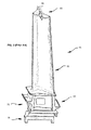
- Fig. 2 depicts a component of the turbine 40; specifically, a turbine bucket or blade 55.
- the turbine bucket 55 includes an airfoil 60 and a root 65.
- the airfoil 60 includes a leading edge and a trailing edge.
- a generally concave pressure surface and a generally convex suction surface extend between the leading and trailing edges on opposing sides of the airfoil 60.
- the root 65 is comprised of a shank 70 and a dovetail 75 that engages a corresponding dovetail groove on a rotor to secure the turbine bucket 55 to the rotor.
- a tip shroud 80 is formed at the tip of the airfoil 60 and extends perpendicularly outward from the surface of the airfoil 60.
- the tip shroud 80 includes radially inward and radially outward facing surfaces and is exposed to the hot compressed gas flowing through the turbine section.
- Each tip shroud 80 has bearing surfaces 85, 90 over which it contacts the tip shroud of an adjacent blade thereby restraining blade vibration.
- a seal rail 95 typically extends radially outward from the radially outward facing surface of the tip shroud 80 to prevent leakage of hot gas around the respective blade row.
- a number of cooling air passages 110 extends radially outwardly through the blade into the blade tip.
- coolant passages may be defined in the airfoil.
- FIG. 4 A system for mode shape identification in turbine buckets is depicted in Fig. 4 .
- the system includes a turbine bucket 55 having a tip shroud 80 as previously described.
- the system includes trigger patterns 100 disposed on the radially outward facing surface of the tip shroud 80.
- a sensor 105 may be disposed adjacent to the radially outward facing surface of the tip shroud 80 for sensing the trigger patterns 100 as the trigger patterns 100 pass the sensor 105.
- the trigger patterns are patterned to identify at least one mode shape of the turbine bucket. Modes are associated with structural resonances. Each mode is defined by a modal frequency, modal dampening, and a mode shape. Mode shapes define the motion of the turbine buckets.
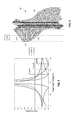
- Fig. 5 illustrates how different trigger patterns may provide greater or lesser probe sensitivity to different turbine bucket mode shapes.
- various trigger angles may provide various levels of probe sensitivity.
- trigger 1 corresponds to trigger 100
- trigger 2 corresponds to trigger 101
- trigger 3 corresponds to trigger 102.
- trigger 1 and its corresponding trigger angle provides the greatest probe sensitivity to mode shape 1 and the poorest probe sensitivity to mode shape 3.
- trigger 3 and its corresponding trigger angle provides the greatest probe sensitivity to mode shape 3 and the poorest probe sensitivity to mode shape 1.
- the trigger patterns may be individually and/or collectively patterned to identify various mode shape of the turbine bucket and to provide greater sensitivity to detecting various mode shapes of the turbine bucket.
- the trigger patterns amplify the deflection observed by the sensor. In other embodiments, the trigger patterns are pattered to distinguish operating deflection shapes from mode shapes of the turbine bucket. Moreover, in other embodiments, the trigger patterns are pattered to determine the direction of the mode shape of the turbine bucket.
- the trigger patterns may be formed by applying a pattern via coating or other means to change the reflectivity of at least a portion of the radially outward facing surface of the tip shroud.
- the trigger patterns may also be formed by carving, etching, or otherwise distorting at least a portion of the radially outward facing surface of the tip shroud.
- the trigger patterns may be any shape, size, and/or configuration necessary to identify various mode shapes of the turbine bucket and to provide greater sensitivity to detecting various mode shapes of the turbine bucket.
- the trigger patterns include three angularly spaced rectangular strips.
- the type and configuration of the sensor 105 may be similar to the sensor devices described in U.S. Pat. No. 7,861,592 , which is herein incorporated by reference.
- the sensor is a laser probe. Accordingly, the change in reflectivity facilitated by the trigger patterns alters the amount of light received from the laser probe.
- the change in reflectivity of at least a portion of the radially outward facing surface of the tip shroud can be used to identify a particular features or groups of features on the turbine bucket by analyzing the time deviations for the bucket to pass the at least one sensor. Using this data, a vibratory deflection may be calculated. Moreover, applying a trigger pattern to at least a portion of the radially outward facing surface of the tip shroud can be used to discern the mode shape from other mode shapes. The trigger pattern can also be used to increase measurement capability and determine the direction of vibratory deflection.
Landscapes
- Engineering & Computer Science (AREA)
- Mechanical Engineering (AREA)
- General Engineering & Computer Science (AREA)
- Physics & Mathematics (AREA)
- General Physics & Mathematics (AREA)
- Turbine Rotor Nozzle Sealing (AREA)
Description
- Embodiments of the present application relate generally to gas turbine engines and more particularly to systems and methods for mode shape identification of turbine buckets.
- A high speed turbo machine, such as, for example, a gas turbine, generally include a number of buckets arranged in axially oriented rows, the rows of buckets being rotated in response to the force of a high pressure fluid flowing axially through the machine. Due to their complex design, natural resonant mechanical frequencies of the buckets may coincide with or be excited by certain bucket rotational speeds and rotational harmonics thereof. Each natural frequency is associated with a particular mode shape, each of which is a different combination of vibrational deflections such as along the rotational axis of the turbine, perpendicular to the rotational axis of the turbine, and so forth.
- In known systems for monitoring and analyzing vibrations in shrouded bucket structures, where the shroud is made integral with the bucket, the shroud may be provided with triggers that are placed in the shroud. One trigger is generally provided to each shroud portion associated with a bucket such that each trigger corresponds to a bucket. In most field test and on-line applications, a sensor may be provided for sensing the arrival of each trigger as the trigger passes the sensor. The data is analyzed on the basis of data identified with each trigger, i.e., each bucket, such that the vibration characteristics of each target location are individually analyzed, based on multiple rotations of the bucket row, to characterize the vibration characteristics of the coupled shroud structure. In such systems, however, it is difficult to discern the mode shape of the buckets.
- Some or all of the above needs and/or problems may be addressed by certain embodiments of the present application. Disclosed embodiments may include systems and methods for mode shape identification. Further, according to a first aspect, there is disclosed a system for mode shape identification. The system can include a rotating element with numerous trigger patterns disposed on the rotating element. A sensor is disposed adjacent to the rotating element for detecting the trigger patterns. The trigger patterns are patterned to identify at least one mode shape of the rotating element. The rotating element may be a turbine bucket.
- According to another aspect, there is disclosed a method for mode shape identification. The method can include providing a turbine bucket. The method can also include patterning triggers at a distal end of the turbine bucket. Moreover, the method can include detecting the triggers with a sensor disposed adjacent to the distal end of the turbine bucket. The trigger patterns are patterned to identify at least one mode shape of the turbine bucket.
- Other embodiments, aspects, and features of the invention will become apparent to those skilled in the art from the following detailed description, the accompanying drawings, and the appended claims.
- Embodiments of the present invention will now be described, by way of example only, with reference to the accompanying drawings in which:
-
FIG. 1 is a schematic of an example diagram of a gas turbine engine with a compressor, a combustor, and a turbine, according to an embodiment. -
FIG. 2 is a schematic of an example turbine bucket, according to an embodiment. -
FIG. 3 is a schematic of an example shrouded turbine bucket, according to an embodiment. -
FIG. 4 is a schematic of an example shrouded turbine bucket including a number of trigger patterns, according to an embodiment. -
FIG. 5 is a graph illustrating probe sensitivity versus trigger angle for various mode shapes of the turbine bucket, according to an embodiment. - Illustrative embodiments will now be described more fully hereinafter with reference to the accompanying drawings, in which some, but not all embodiments are shown. The present application may be embodied in many different forms and should not be construed as limited to the embodiments set forth herein; rather, these embodiments are provided so that this disclosure will satisfy applicable legal requirements. Like numbers refer to like elements throughout.
- Illustrative embodiments are directed to, among other things, systems and methods for mode shape identification of turbine buckets or other rotating elements.
Fig. 1 shows a schematic view of agas turbine engine 10 as may be used herein. As is known, thegas turbine engine 10 may include acompressor 15. Thecompressor 15 compresses an incoming flow ofair 20. Thecompressor 15 delivers the compressed flow ofair 20 to acombustor 25. Thecombustor 25 mixes the compressed flow ofair 20 with a pressurized flow offuel 30 and ignites the mixture to create a flow ofcombustion gases 35. Although only asingle combustor 25 is shown, thegas turbine engine 10 may include any number ofcombustors 25. The flow ofcombustion gases 35 is in turn delivered to aturbine 40. The flow ofcombustion gases 35 drives theturbine 40 so as to produce mechanical work. The mechanical work produced in theturbine 40 drives thecompressor 15 via ashaft 45 and anexternal load 50 such as an electrical generator and the like. - The
gas turbine engine 10 may use natural gas, various types of syngas, and/or other types of fuels. Thegas turbine engine 10 may be any one of a number of different gas turbine engines offered by General Electric Company of Schenectady, New York, including, but not limited to, those such as a 7 or a 9 series heavy duty gas turbine engine and the like. Thegas turbine engine 10 may have different configurations and may use other types of components. - Other types of gas turbine engines also may be used herein. Multiple gas turbine engines, other types of turbines, and other types of power generation equipment also may be used herein together.
-
Fig. 2 depicts a component of theturbine 40; specifically, a turbine bucket orblade 55. Theturbine bucket 55 includes anairfoil 60 and aroot 65. Theairfoil 60 includes a leading edge and a trailing edge. A generally concave pressure surface and a generally convex suction surface extend between the leading and trailing edges on opposing sides of theairfoil 60. In the illustrated example, theroot 65 is comprised of ashank 70 and adovetail 75 that engages a corresponding dovetail groove on a rotor to secure theturbine bucket 55 to the rotor. - As collectively depicted in
Figs. 2 and3 , atip shroud 80 is formed at the tip of theairfoil 60 and extends perpendicularly outward from the surface of theairfoil 60. Thetip shroud 80 includes radially inward and radially outward facing surfaces and is exposed to the hot compressed gas flowing through the turbine section. Eachtip shroud 80 has bearingsurfaces seal rail 95 typically extends radially outward from the radially outward facing surface of thetip shroud 80 to prevent leakage of hot gas around the respective blade row. In some conventional turbine blade structures, a number ofcooling air passages 110 extends radially outwardly through the blade into the blade tip. In other conventional turbine blade structures, coolant passages may be defined in the airfoil. - A system for mode shape identification in turbine buckets is depicted in
Fig. 4 . The system includes aturbine bucket 55 having atip shroud 80 as previously described. Moreover, the system includestrigger patterns 100 disposed on the radially outward facing surface of thetip shroud 80. Asensor 105 may be disposed adjacent to the radially outward facing surface of thetip shroud 80 for sensing thetrigger patterns 100 as thetrigger patterns 100 pass thesensor 105. - The trigger patterns are patterned to identify at least one mode shape of the turbine bucket. Modes are associated with structural resonances. Each mode is defined by a modal frequency, modal dampening, and a mode shape. Mode shapes define the motion of the turbine buckets.
-
Fig. 5 illustrates how different trigger patterns may provide greater or lesser probe sensitivity to different turbine bucket mode shapes. For example, depending on the mode shape of the turbine bucket, various trigger angles may provide various levels of probe sensitivity. InFigs. 4 and 5 ,trigger 1 corresponds to trigger 100,trigger 2 corresponds to trigger 101, andtrigger 3 corresponds to trigger 102. As graphically illustrated inFig. 5 ,trigger 1 and its corresponding trigger angle provides the greatest probe sensitivity tomode shape 1 and the poorest probe sensitivity tomode shape 3. Conversely,trigger 3 and its corresponding trigger angle provides the greatest probe sensitivity tomode shape 3 and the poorest probe sensitivity tomode shape 1. Accordingly, the trigger patterns may be individually and/or collectively patterned to identify various mode shape of the turbine bucket and to provide greater sensitivity to detecting various mode shapes of the turbine bucket. - In certain embodiments, the trigger patterns amplify the deflection observed by the sensor. In other embodiments, the trigger patterns are pattered to distinguish operating deflection shapes from mode shapes of the turbine bucket. Moreover, in other embodiments, the trigger patterns are pattered to determine the direction of the mode shape of the turbine bucket.
- The trigger patterns may be formed by applying a pattern via coating or other means to change the reflectivity of at least a portion of the radially outward facing surface of the tip shroud. The trigger patterns may also be formed by carving, etching, or otherwise distorting at least a portion of the radially outward facing surface of the tip shroud. The trigger patterns may be any shape, size, and/or configuration necessary to identify various mode shapes of the turbine bucket and to provide greater sensitivity to detecting various mode shapes of the turbine bucket. For example, as depicted in
Fig. 4 , the trigger patterns include three angularly spaced rectangular strips. - The type and configuration of the
sensor 105 may be similar to the sensor devices described inU.S. Pat. No. 7,861,592 , which is herein incorporated by reference. For example, in certain illustrative embodiments, the sensor is a laser probe. Accordingly, the change in reflectivity facilitated by the trigger patterns alters the amount of light received from the laser probe. - The change in reflectivity of at least a portion of the radially outward facing surface of the tip shroud can be used to identify a particular features or groups of features on the turbine bucket by analyzing the time deviations for the bucket to pass the at least one sensor. Using this data, a vibratory deflection may be calculated. Moreover, applying a trigger pattern to at least a portion of the radially outward facing surface of the tip shroud can be used to discern the mode shape from other mode shapes. The trigger pattern can also be used to increase measurement capability and determine the direction of vibratory deflection.
- The present systems and methods for mode shape identification have been described in relation to turbine buckets. However, other applications employing rotating elements are envisioned. Moreover, although embodiments have been described in language specific to structural features and/or methodological acts, it is to be understood that the disclosure is not necessarily limited to the specific features or acts described. Rather, the specific features and acts are disclosed as illustrative forms of implementing the embodiments.
Claims (14)
- A system for mode shape identification, comprising:a rotating element (55);a plurality of trigger patterns (100) disposed at a distal end of the rotating element (55); andat least one sensor (105) disposed adjacent to the distal end of the rotating element (55) for detecting the plurality of trigger patterns (100);wherein the plurality of trigger patterns (100) is patterned to identify at least one mode shape of the rotating element (55).
- The system of claim 1, wherein the rotating element is a turbine bucket (55) and the distal end of the turbine bucket (55) includes a shroud (80).
- The system of claim 2, wherein the plurality of trigger patterns (100) are disposed on an outer surface of the shroud (80).
- The system of any of claims 1 to 3, wherein the sensor (105) is a laser probe.
- The system of any of claims 1 to 4, wherein the plurality of trigger patterns (100) amplify a deflection observed by the at least one sensor (105).
- The system of any of claims 1 to 5, wherein the plurality of trigger patterns (100) is pattered to distinguish operating deflection shapes from mode shapes of the rotating element (55).
- The system of claim 1 to 5, wherein the plurality of trigger patterns (100) is pattered to determine a direction of the mode shape of the rotating element (55).
- A method for mode shape identification, comprising:patterning a plurality of triggers (100) at a distal end of a rotating element (55); anddetecting the plurality of triggers (100) with at least one sensor (105) disposed adjacent to the distal end of the rotating element (55);wherein the plurality of triggers (100) is patterned to identify specific mode shapes of the rotating element (55);
- The method of claim 8, wherein the rotating element is a turbine bucket and distal end of the turbine bucket (55) includes a shroud (80).
- The method of claim 9, wherein the plurality of triggers (100) is patterned on an outer surface of the shroud (80).
- The method of any of claims 8 to 10, wherein the sensor (105) is a laser probe.
- The method of any of claims 8 to 11, wherein the plurality of triggers (100) amplify a deflection observed by the at least one sensor (105).
- The method of any of claims 8 to 12, wherein the plurality of triggers (100) is pattered to distinguish operating deflection shapes from mode shapes of the rotating element (55).
- The method of any of claims 8 to 12, wherein the plurality of triggers (100) is pattered to determine a direction of the mode shape of the rotating element (55).
Applications Claiming Priority (1)
| Application Number | Priority Date | Filing Date | Title |
|---|---|---|---|
| US13/246,309 US8689634B2 (en) | 2011-09-27 | 2011-09-27 | Systems and methods for mode shape identification |
Publications (3)
| Publication Number | Publication Date |
|---|---|
| EP2574734A2 true EP2574734A2 (en) | 2013-04-03 |
| EP2574734A3 EP2574734A3 (en) | 2017-09-20 |
| EP2574734B1 EP2574734B1 (en) | 2018-11-14 |
Family
ID=47221923
Family Applications (1)
| Application Number | Title | Priority Date | Filing Date |
|---|---|---|---|
| EP12184551.5A Active EP2574734B1 (en) | 2011-09-27 | 2012-09-14 | Systems and methods for mode shape identification |
Country Status (3)
| Country | Link |
|---|---|
| US (1) | US8689634B2 (en) |
| EP (1) | EP2574734B1 (en) |
| CN (1) | CN103017885B (en) |
Cited By (1)
| Publication number | Priority date | Publication date | Assignee | Title |
|---|---|---|---|---|
| EP2808497A1 (en) * | 2013-05-30 | 2014-12-03 | Rolls-Royce plc | Blade tip timing |
Citations (1)
| Publication number | Priority date | Publication date | Assignee | Title |
|---|---|---|---|---|
| US7861592B2 (en) | 2007-02-27 | 2011-01-04 | Siemens Energy, Inc. | Blade shroud vibration monitor |
Family Cites Families (15)
| Publication number | Priority date | Publication date | Assignee | Title |
|---|---|---|---|---|
| US4373804A (en) * | 1979-04-30 | 1983-02-15 | Diffracto Ltd. | Method and apparatus for electro-optically determining the dimension, location and attitude of objects |
| US4422333A (en) * | 1982-04-29 | 1983-12-27 | The Franklin Institute | Method and apparatus for detecting and identifying excessively vibrating blades of a turbomachine |
| US5097711A (en) * | 1990-10-29 | 1992-03-24 | Westinghouse Electric Corp. | Shrouded turbine blade vibration monitor and target therefor |
| US5365663A (en) * | 1992-04-28 | 1994-11-22 | Westinghouse Electric Corporation | Method of attaching a monitor target to a shrouded blade |
| FR2695205B1 (en) * | 1992-09-03 | 1994-11-18 | Europ Propulsion | Method and device for measuring vibration of turbine blades in operation. |
| US5471880A (en) * | 1994-04-28 | 1995-12-05 | Electric Power Research Institute | Method and apparatus for isolating and identifying periodic Doppler signals in a turbine |
| US6094989A (en) * | 1998-08-21 | 2000-08-01 | Siemens Westinghouse Power Corporation | Method and apparatus for analyzing non-synchronous blade vibrations using unevenly spaced probes |
| FR2807834B1 (en) * | 2000-04-13 | 2002-06-28 | Snecma Moteurs | NON-CONTACT MEASUREMENT METHOD OF VIBRATION OF A ROTATING BODY |
| US7082371B2 (en) * | 2003-05-29 | 2006-07-25 | Carnegie Mellon University | Fundamental mistuning model for determining system properties and predicting vibratory response of bladed disks |
| US8096184B2 (en) * | 2004-06-30 | 2012-01-17 | Siemens Energy, Inc. | Turbine blade for monitoring blade vibration |
| US7509862B2 (en) * | 2007-01-24 | 2009-03-31 | Massachusetts Institute Of Technology | System and method for providing vibration detection in turbomachinery |
| CA2686702C (en) * | 2007-04-30 | 2016-08-16 | Nuovo Pignone, S.P.A. | Method and system for turbine blade characterization |
| US20090142194A1 (en) * | 2007-11-30 | 2009-06-04 | General Electric Company | Method and systems for measuring blade deformation in turbines |
| JP4560110B2 (en) * | 2008-09-17 | 2010-10-13 | ジヤトコ株式会社 | Abnormality diagnosis apparatus and abnormality diagnosis method |
| US8256297B2 (en) * | 2010-01-05 | 2012-09-04 | General Electric Company | Systems and methods for measuring turbine blade vibratory response |
-
2011
- 2011-09-27 US US13/246,309 patent/US8689634B2/en active Active
-
2012
- 2012-09-14 EP EP12184551.5A patent/EP2574734B1/en active Active
- 2012-09-27 CN CN201210374671.5A patent/CN103017885B/en active Active
Patent Citations (1)
| Publication number | Priority date | Publication date | Assignee | Title |
|---|---|---|---|---|
| US7861592B2 (en) | 2007-02-27 | 2011-01-04 | Siemens Energy, Inc. | Blade shroud vibration monitor |
Cited By (2)
| Publication number | Priority date | Publication date | Assignee | Title |
|---|---|---|---|---|
| EP2808497A1 (en) * | 2013-05-30 | 2014-12-03 | Rolls-Royce plc | Blade tip timing |
| US9528387B2 (en) | 2013-05-30 | 2016-12-27 | Rolls-Royce Plc | Blade tip timing |
Also Published As
| Publication number | Publication date |
|---|---|
| US8689634B2 (en) | 2014-04-08 |
| CN103017885B (en) | 2018-12-18 |
| EP2574734A3 (en) | 2017-09-20 |
| CN103017885A (en) | 2013-04-03 |
| EP2574734B1 (en) | 2018-11-14 |
| US20130078094A1 (en) | 2013-03-28 |
Similar Documents
| Publication | Publication Date | Title |
|---|---|---|
| US9151167B2 (en) | Turbine assembly | |
| EP3139003B1 (en) | Damper pin for turbine blades and corresponding turbine engine | |
| EP2650476B1 (en) | Turbomachine blade tip shroud with parallel casing configuration | |
| EP3139002B1 (en) | Damper pin for turbine blades and corresponding turbine engine | |
| US8297919B2 (en) | Turbine airfoil clocking | |
| EP3139001B1 (en) | Damper pin for turbine blades and corresponding turbine engine | |
| US10385701B2 (en) | Damper pin for a turbine blade | |
| US9759070B2 (en) | Turbine bucket tip shroud | |
| US10907491B2 (en) | Sealing system for a rotary machine and method of assembling same | |
| US10633983B2 (en) | Airfoil tip geometry to reduce blade wear in gas turbine engines | |
| EP3138999B1 (en) | Damper pin for damping adjacent turbine blades and turbine engine | |
| JP2010059968A (en) | Turbine airfoil clocking | |
| US9957834B2 (en) | Rotor blade tip clearance | |
| US10385865B2 (en) | Airfoil tip geometry to reduce blade wear in gas turbine engines | |
| EP2871440A1 (en) | Bucket tip shroud measurement fixture for measuring bucket tip shroud orientation | |
| CN113446067A (en) | Improved rotor blade damping structure | |
| US8689634B2 (en) | Systems and methods for mode shape identification | |
| CN113984311A (en) | Full-engine order blade disc excitation test device and engine order distance ruler | |
| US9719355B2 (en) | Rotary machine blade having an asymmetric part-span shroud and method of making same | |
| US20250109691A1 (en) | Turbine | |
| EP3006673A1 (en) | Method for and arrangement for measuring shrouded blade interlock wear | |
| US20170191366A1 (en) | Slotted damper pin for a turbine blade | |
| EP2997230B1 (en) | Tangential blade root neck conic | |
| CN108798795B (en) | Turbulence sensor for a turbomachine compressor | |
| US12298197B2 (en) | System and method for reducing motoring time in a turbomachine based on shaft deflection |
Legal Events
| Date | Code | Title | Description |
|---|---|---|---|
| PUAI | Public reference made under article 153(3) epc to a published international application that has entered the european phase |
Free format text: ORIGINAL CODE: 0009012 |
|
| AK | Designated contracting states |
Kind code of ref document: A2 Designated state(s): AL AT BE BG CH CY CZ DE DK EE ES FI FR GB GR HR HU IE IS IT LI LT LU LV MC MK MT NL NO PL PT RO RS SE SI SK SM TR |
|
| AX | Request for extension of the european patent |
Extension state: BA ME |
|
| PUAL | Search report despatched |
Free format text: ORIGINAL CODE: 0009013 |
|
| AK | Designated contracting states |
Kind code of ref document: A3 Designated state(s): AL AT BE BG CH CY CZ DE DK EE ES FI FR GB GR HR HU IE IS IT LI LT LU LV MC MK MT NL NO PL PT RO RS SE SI SK SM TR |
|
| AX | Request for extension of the european patent |
Extension state: BA ME |
|
| RIC1 | Information provided on ipc code assigned before grant |
Ipc: F01D 17/02 20060101ALI20170811BHEP Ipc: F01D 25/06 20060101ALI20170811BHEP Ipc: G01H 1/00 20060101ALI20170811BHEP Ipc: F01D 25/04 20060101ALI20170811BHEP Ipc: F01D 21/00 20060101AFI20170811BHEP Ipc: G01H 1/06 20060101ALI20170811BHEP |
|
| STAA | Information on the status of an ep patent application or granted ep patent |
Free format text: STATUS: REQUEST FOR EXAMINATION WAS MADE |
|
| 17P | Request for examination filed |
Effective date: 20180320 |
|
| RBV | Designated contracting states (corrected) |
Designated state(s): AL AT BE BG CH CY CZ DE DK EE ES FI FR GB GR HR HU IE IS IT LI LT LU LV MC MK MT NL NO PL PT RO RS SE SI SK SM TR |
|
| RIC1 | Information provided on ipc code assigned before grant |
Ipc: F01D 25/04 20060101ALI20180405BHEP Ipc: G01H 1/00 20060101ALI20180405BHEP Ipc: F01D 17/02 20060101ALI20180405BHEP Ipc: G01H 1/06 20060101ALI20180405BHEP Ipc: F01D 21/00 20060101AFI20180405BHEP Ipc: F01D 25/06 20060101ALI20180405BHEP |
|
| GRAP | Despatch of communication of intention to grant a patent |
Free format text: ORIGINAL CODE: EPIDOSNIGR1 |
|
| STAA | Information on the status of an ep patent application or granted ep patent |
Free format text: STATUS: GRANT OF PATENT IS INTENDED |
|
| INTG | Intention to grant announced |
Effective date: 20180514 |
|
| GRAS | Grant fee paid |
Free format text: ORIGINAL CODE: EPIDOSNIGR3 |
|
| GRAA | (expected) grant |
Free format text: ORIGINAL CODE: 0009210 |
|
| STAA | Information on the status of an ep patent application or granted ep patent |
Free format text: STATUS: THE PATENT HAS BEEN GRANTED |
|
| AK | Designated contracting states |
Kind code of ref document: B1 Designated state(s): AL AT BE BG CH CY CZ DE DK EE ES FI FR GB GR HR HU IE IS IT LI LT LU LV MC MK MT NL NO PL PT RO RS SE SI SK SM TR |
|
| REG | Reference to a national code |
Ref country code: CH Ref legal event code: EP Ref country code: AT Ref legal event code: REF Ref document number: 1065071 Country of ref document: AT Kind code of ref document: T Effective date: 20181115 |
|
| REG | Reference to a national code |
Ref country code: IE Ref legal event code: FG4D |
|
| REG | Reference to a national code |
Ref country code: DE Ref legal event code: R096 Ref document number: 602012053410 Country of ref document: DE |
|
| REG | Reference to a national code |
Ref country code: NL Ref legal event code: MP Effective date: 20181114 |
|
| REG | Reference to a national code |
Ref country code: LT Ref legal event code: MG4D |
|
| REG | Reference to a national code |
Ref country code: AT Ref legal event code: MK05 Ref document number: 1065071 Country of ref document: AT Kind code of ref document: T Effective date: 20181114 |
|
| PG25 | Lapsed in a contracting state [announced via postgrant information from national office to epo] |
Ref country code: LV Free format text: LAPSE BECAUSE OF FAILURE TO SUBMIT A TRANSLATION OF THE DESCRIPTION OR TO PAY THE FEE WITHIN THE PRESCRIBED TIME-LIMIT Effective date: 20181114 Ref country code: AT Free format text: LAPSE BECAUSE OF FAILURE TO SUBMIT A TRANSLATION OF THE DESCRIPTION OR TO PAY THE FEE WITHIN THE PRESCRIBED TIME-LIMIT Effective date: 20181114 Ref country code: FI Free format text: LAPSE BECAUSE OF FAILURE TO SUBMIT A TRANSLATION OF THE DESCRIPTION OR TO PAY THE FEE WITHIN THE PRESCRIBED TIME-LIMIT Effective date: 20181114 Ref country code: BG Free format text: LAPSE BECAUSE OF FAILURE TO SUBMIT A TRANSLATION OF THE DESCRIPTION OR TO PAY THE FEE WITHIN THE PRESCRIBED TIME-LIMIT Effective date: 20190214 Ref country code: IS Free format text: LAPSE BECAUSE OF FAILURE TO SUBMIT A TRANSLATION OF THE DESCRIPTION OR TO PAY THE FEE WITHIN THE PRESCRIBED TIME-LIMIT Effective date: 20190314 Ref country code: NO Free format text: LAPSE BECAUSE OF FAILURE TO SUBMIT A TRANSLATION OF THE DESCRIPTION OR TO PAY THE FEE WITHIN THE PRESCRIBED TIME-LIMIT Effective date: 20190214 Ref country code: HR Free format text: LAPSE BECAUSE OF FAILURE TO SUBMIT A TRANSLATION OF THE DESCRIPTION OR TO PAY THE FEE WITHIN THE PRESCRIBED TIME-LIMIT Effective date: 20181114 Ref country code: ES Free format text: LAPSE BECAUSE OF FAILURE TO SUBMIT A TRANSLATION OF THE DESCRIPTION OR TO PAY THE FEE WITHIN THE PRESCRIBED TIME-LIMIT Effective date: 20181114 Ref country code: LT Free format text: LAPSE BECAUSE OF FAILURE TO SUBMIT A TRANSLATION OF THE DESCRIPTION OR TO PAY THE FEE WITHIN THE PRESCRIBED TIME-LIMIT Effective date: 20181114 |
|
| PG25 | Lapsed in a contracting state [announced via postgrant information from national office to epo] |
Ref country code: SE Free format text: LAPSE BECAUSE OF FAILURE TO SUBMIT A TRANSLATION OF THE DESCRIPTION OR TO PAY THE FEE WITHIN THE PRESCRIBED TIME-LIMIT Effective date: 20181114 Ref country code: NL Free format text: LAPSE BECAUSE OF FAILURE TO SUBMIT A TRANSLATION OF THE DESCRIPTION OR TO PAY THE FEE WITHIN THE PRESCRIBED TIME-LIMIT Effective date: 20181114 Ref country code: GR Free format text: LAPSE BECAUSE OF FAILURE TO SUBMIT A TRANSLATION OF THE DESCRIPTION OR TO PAY THE FEE WITHIN THE PRESCRIBED TIME-LIMIT Effective date: 20190215 Ref country code: PT Free format text: LAPSE BECAUSE OF FAILURE TO SUBMIT A TRANSLATION OF THE DESCRIPTION OR TO PAY THE FEE WITHIN THE PRESCRIBED TIME-LIMIT Effective date: 20190314 Ref country code: AL Free format text: LAPSE BECAUSE OF FAILURE TO SUBMIT A TRANSLATION OF THE DESCRIPTION OR TO PAY THE FEE WITHIN THE PRESCRIBED TIME-LIMIT Effective date: 20181114 Ref country code: RS Free format text: LAPSE BECAUSE OF FAILURE TO SUBMIT A TRANSLATION OF THE DESCRIPTION OR TO PAY THE FEE WITHIN THE PRESCRIBED TIME-LIMIT Effective date: 20181114 |
|
| PG25 | Lapsed in a contracting state [announced via postgrant information from national office to epo] |
Ref country code: CZ Free format text: LAPSE BECAUSE OF FAILURE TO SUBMIT A TRANSLATION OF THE DESCRIPTION OR TO PAY THE FEE WITHIN THE PRESCRIBED TIME-LIMIT Effective date: 20181114 Ref country code: PL Free format text: LAPSE BECAUSE OF FAILURE TO SUBMIT A TRANSLATION OF THE DESCRIPTION OR TO PAY THE FEE WITHIN THE PRESCRIBED TIME-LIMIT Effective date: 20181114 Ref country code: DK Free format text: LAPSE BECAUSE OF FAILURE TO SUBMIT A TRANSLATION OF THE DESCRIPTION OR TO PAY THE FEE WITHIN THE PRESCRIBED TIME-LIMIT Effective date: 20181114 |
|
| REG | Reference to a national code |
Ref country code: DE Ref legal event code: R097 Ref document number: 602012053410 Country of ref document: DE |
|
| PG25 | Lapsed in a contracting state [announced via postgrant information from national office to epo] |
Ref country code: RO Free format text: LAPSE BECAUSE OF FAILURE TO SUBMIT A TRANSLATION OF THE DESCRIPTION OR TO PAY THE FEE WITHIN THE PRESCRIBED TIME-LIMIT Effective date: 20181114 Ref country code: SK Free format text: LAPSE BECAUSE OF FAILURE TO SUBMIT A TRANSLATION OF THE DESCRIPTION OR TO PAY THE FEE WITHIN THE PRESCRIBED TIME-LIMIT Effective date: 20181114 Ref country code: EE Free format text: LAPSE BECAUSE OF FAILURE TO SUBMIT A TRANSLATION OF THE DESCRIPTION OR TO PAY THE FEE WITHIN THE PRESCRIBED TIME-LIMIT Effective date: 20181114 Ref country code: SM Free format text: LAPSE BECAUSE OF FAILURE TO SUBMIT A TRANSLATION OF THE DESCRIPTION OR TO PAY THE FEE WITHIN THE PRESCRIBED TIME-LIMIT Effective date: 20181114 |
|
| PLBE | No opposition filed within time limit |
Free format text: ORIGINAL CODE: 0009261 |
|
| STAA | Information on the status of an ep patent application or granted ep patent |
Free format text: STATUS: NO OPPOSITION FILED WITHIN TIME LIMIT |
|
| 26N | No opposition filed |
Effective date: 20190815 |
|
| PG25 | Lapsed in a contracting state [announced via postgrant information from national office to epo] |
Ref country code: SI Free format text: LAPSE BECAUSE OF FAILURE TO SUBMIT A TRANSLATION OF THE DESCRIPTION OR TO PAY THE FEE WITHIN THE PRESCRIBED TIME-LIMIT Effective date: 20181114 |
|
| PGFP | Annual fee paid to national office [announced via postgrant information from national office to epo] |
Ref country code: IT Payment date: 20190829 Year of fee payment: 8 |
|
| PGFP | Annual fee paid to national office [announced via postgrant information from national office to epo] |
Ref country code: GB Payment date: 20190820 Year of fee payment: 8 |
|
| PG25 | Lapsed in a contracting state [announced via postgrant information from national office to epo] |
Ref country code: TR Free format text: LAPSE BECAUSE OF FAILURE TO SUBMIT A TRANSLATION OF THE DESCRIPTION OR TO PAY THE FEE WITHIN THE PRESCRIBED TIME-LIMIT Effective date: 20181114 |
|
| PG25 | Lapsed in a contracting state [announced via postgrant information from national office to epo] |
Ref country code: MC Free format text: LAPSE BECAUSE OF FAILURE TO SUBMIT A TRANSLATION OF THE DESCRIPTION OR TO PAY THE FEE WITHIN THE PRESCRIBED TIME-LIMIT Effective date: 20181114 |
|
| REG | Reference to a national code |
Ref country code: CH Ref legal event code: PL |
|
| PG25 | Lapsed in a contracting state [announced via postgrant information from national office to epo] |
Ref country code: IE Free format text: LAPSE BECAUSE OF NON-PAYMENT OF DUE FEES Effective date: 20190914 Ref country code: LU Free format text: LAPSE BECAUSE OF NON-PAYMENT OF DUE FEES Effective date: 20190914 Ref country code: CH Free format text: LAPSE BECAUSE OF NON-PAYMENT OF DUE FEES Effective date: 20190930 Ref country code: LI Free format text: LAPSE BECAUSE OF NON-PAYMENT OF DUE FEES Effective date: 20190930 |
|
| REG | Reference to a national code |
Ref country code: BE Ref legal event code: MM Effective date: 20190930 |
|
| PG25 | Lapsed in a contracting state [announced via postgrant information from national office to epo] |
Ref country code: BE Free format text: LAPSE BECAUSE OF NON-PAYMENT OF DUE FEES Effective date: 20190930 |
|
| PG25 | Lapsed in a contracting state [announced via postgrant information from national office to epo] |
Ref country code: FR Free format text: LAPSE BECAUSE OF NON-PAYMENT OF DUE FEES Effective date: 20190930 |
|
| GBPC | Gb: european patent ceased through non-payment of renewal fee |
Effective date: 20200914 |
|
| PG25 | Lapsed in a contracting state [announced via postgrant information from national office to epo] |
Ref country code: CY Free format text: LAPSE BECAUSE OF FAILURE TO SUBMIT A TRANSLATION OF THE DESCRIPTION OR TO PAY THE FEE WITHIN THE PRESCRIBED TIME-LIMIT Effective date: 20181114 |
|
| PG25 | Lapsed in a contracting state [announced via postgrant information from national office to epo] |
Ref country code: MT Free format text: LAPSE BECAUSE OF FAILURE TO SUBMIT A TRANSLATION OF THE DESCRIPTION OR TO PAY THE FEE WITHIN THE PRESCRIBED TIME-LIMIT Effective date: 20181114 Ref country code: HU Free format text: LAPSE BECAUSE OF FAILURE TO SUBMIT A TRANSLATION OF THE DESCRIPTION OR TO PAY THE FEE WITHIN THE PRESCRIBED TIME-LIMIT; INVALID AB INITIO Effective date: 20120914 |
|
| PG25 | Lapsed in a contracting state [announced via postgrant information from national office to epo] |
Ref country code: GB Free format text: LAPSE BECAUSE OF NON-PAYMENT OF DUE FEES Effective date: 20200914 |
|
| PG25 | Lapsed in a contracting state [announced via postgrant information from national office to epo] |
Ref country code: IT Free format text: LAPSE BECAUSE OF NON-PAYMENT OF DUE FEES Effective date: 20200914 |
|
| PG25 | Lapsed in a contracting state [announced via postgrant information from national office to epo] |
Ref country code: MK Free format text: LAPSE BECAUSE OF FAILURE TO SUBMIT A TRANSLATION OF THE DESCRIPTION OR TO PAY THE FEE WITHIN THE PRESCRIBED TIME-LIMIT Effective date: 20181114 |
|
| REG | Reference to a national code |
Ref country code: DE Ref legal event code: R081 Ref document number: 602012053410 Country of ref document: DE Owner name: GENERAL ELECTRIC TECHNOLOGY GMBH, CH Free format text: FORMER OWNER: GENERAL ELECTRIC COMPANY, SCHENECTADY, NY, US |
|
| PGFP | Annual fee paid to national office [announced via postgrant information from national office to epo] |
Ref country code: DE Payment date: 20250820 Year of fee payment: 14 |