EP2574728A1 - Clearance flow control assembly having rail member and corresponding turbine - Google Patents
Clearance flow control assembly having rail member and corresponding turbine Download PDFInfo
- Publication number
- EP2574728A1 EP2574728A1 EP12185988A EP12185988A EP2574728A1 EP 2574728 A1 EP2574728 A1 EP 2574728A1 EP 12185988 A EP12185988 A EP 12185988A EP 12185988 A EP12185988 A EP 12185988A EP 2574728 A1 EP2574728 A1 EP 2574728A1
- Authority
- EP
- European Patent Office
- Prior art keywords
- chamber
- control assembly
- flow control
- flow
- wall
- Prior art date
- Legal status (The legal status is an assumption and is not a legal conclusion. Google has not performed a legal analysis and makes no representation as to the accuracy of the status listed.)
- Withdrawn
Links
- 239000012530 fluid Substances 0.000 claims abstract description 26
- 238000011144 upstream manufacturing Methods 0.000 claims abstract description 21
- 238000001816 cooling Methods 0.000 claims description 8
- 230000007704 transition Effects 0.000 claims description 3
- 230000009467 reduction Effects 0.000 description 4
- 230000004075 alteration Effects 0.000 description 1
- 230000006399 behavior Effects 0.000 description 1
- 230000006872 improvement Effects 0.000 description 1
- 238000004088 simulation Methods 0.000 description 1
- 239000003351 stiffener Substances 0.000 description 1
- 238000006467 substitution reaction Methods 0.000 description 1
Images



Classifications
-
- F—MECHANICAL ENGINEERING; LIGHTING; HEATING; WEAPONS; BLASTING
- F01—MACHINES OR ENGINES IN GENERAL; ENGINE PLANTS IN GENERAL; STEAM ENGINES
- F01D—NON-POSITIVE DISPLACEMENT MACHINES OR ENGINES, e.g. STEAM TURBINES
- F01D5/00—Blades; Blade-carrying members; Heating, heat-insulating, cooling or antivibration means on the blades or the members
- F01D5/12—Blades
- F01D5/22—Blade-to-blade connections, e.g. for damping vibrations
- F01D5/225—Blade-to-blade connections, e.g. for damping vibrations by shrouding
-
- F—MECHANICAL ENGINEERING; LIGHTING; HEATING; WEAPONS; BLASTING
- F01—MACHINES OR ENGINES IN GENERAL; ENGINE PLANTS IN GENERAL; STEAM ENGINES
- F01D—NON-POSITIVE DISPLACEMENT MACHINES OR ENGINES, e.g. STEAM TURBINES
- F01D11/00—Preventing or minimising internal leakage of working-fluid, e.g. between stages
- F01D11/08—Preventing or minimising internal leakage of working-fluid, e.g. between stages for sealing space between rotor blade tips and stator
- F01D11/12—Preventing or minimising internal leakage of working-fluid, e.g. between stages for sealing space between rotor blade tips and stator using a rubstrip, e.g. erodible. deformable or resiliently-biased part
- F01D11/122—Preventing or minimising internal leakage of working-fluid, e.g. between stages for sealing space between rotor blade tips and stator using a rubstrip, e.g. erodible. deformable or resiliently-biased part with erodable or abradable material
Definitions
- the subject matter disclosed herein relates to a flow control assembly, and more specifically to a flow control assembly having a wall with first and second chambers, where the second chamber directs a fluid path into a vortex configuration.
- a turbine stage of a gas engine turbine includes a row of stationary vanes followed by a row of rotating blades in an annular turbine casing.
- the flow of fluid through the turbine casing is partially expanded in the stationary vanes and directed toward the rotating blades, and is further expanded to generate power.
- turbine buckets are provided with a cover for improved aerodynamic and mechanical performance. A rail protruding out of the cover is used to reduce the physical clearance between the turbine casing and the rotating blade. The clearance requirement varies based on the dynamic and thermal behaviors of the rotor and the turbine casing.
- the clearance requirement between the turbine casing and the rotating blade is relatively high, then a relatively high amount of high energy fluid flow is able to escape between the tip of the blade and the interior surface of the turbine casing without generating any useful power during turbine operations.
- the escaping high energy fluid flow constitutes tip clearance loss and can be one of the major sources of losses in the turbine stages. For example, in some cases, the tip clearance losses constitute 20-25% of the total losses in a turbine stage.
- any reduction in the amount of tip clearance flow can result in a direct gain in power and performance of the turbine stage.
- reductions can be achieved by reducing the physical clearance between the rotor tip and the turbine casing.
- This reduction also increases the chance rubbing or interference between the rotating and stationary components.
- Another approach to reduce the tip clearance flow involves reducing the effective clearance between the rotor tip and casing by employing a duel vortex chamber in the turbine casing.
- this approach may be difficult to implement due to aerodynamic issues in the turbine.
- a flow control assembly including a member and a wall.
- the member has a surface, a flow diverting member and a rail member.
- the rail member is situated upstream of the flow diverting member.
- the flow diverting member and the rail member each project from the surface of the member.
- the flow diverting member has a distal end.
- the wall is disposed in relation to the member to create a clearance gap between the distal end of the flow diverting member and the wall.
- a fluid path is created between the member and the wall, and flows from an upstream section and through the clearance gap.
- a first chamber and a second chamber are defined by the wall and located upstream of the clearance gap.
- the rail member diverts the fluid path in the first chamber into a generally curved configuration and the second chamber directs the fluid path into a vortex configuration.
- FIG. 1 is an illustration of an exemplary flow control assembly 10.
- the flow control assembly 10 includes a member 20 and a wall 22.
- the member 20 includes a flow diverting member 30 and a rail member 32. Both the flow diverting member 30 and the rail member 32 project outwardly from an outer surface 34 of the member 20, and towards the wall 22.
- the wall 22 is disposed in relation to a distal end 36 of the member 20 to create a clearance gap 38.
- FIG. 2 illustrates that the clearance gap 38 includes an actual clearance gap A as well as an effective clearance gap E.
- a fluid path 40 is provided between the member 20 and the wall 22, where the fluid path 40 flows from an upstream section 42 and through the clearance gap 38.
- the flow control assembly 10 may be employed in a gas turbine engine.
- the member 20 may be a rotatable turbine blade and the wall 22 is part of a turbine casing 48 that perimetrically surrounds the turbine blade.
- the wall 22 includes a first chamber 44 and a second chamber 46. Both the first chamber 44 and the second chamber 46 are located upstream of the clearance gap 38, and the first chamber 44 is located upstream of the second chamber 46.
- the first chamber 44 includes a generally curved or concave configuration.
- a protrusion 50 is located between the first and second chamber 44 and 46. In the embodiment as illustrated in FIG. 1 , the protrusion 50 is situated downstream of the rail member 32 and upstream of the flow diverting member 30.
- FIG. 1 also illustrates the second chamber 46 transitioning from the protrusion 50 in a generally filleted configuration 52.
- the fluid path 40 is directed to flow into the first and second chambers 44, 46 in a singular vortex configuration prior to flowing through the clearance gap 38.
- the rail member 32 is situated along the outer surface 34 of the member 20 to divert the fluid path 40 in the first chamber 44 into a generally curved configuration.
- the fluid path 40 then flows around a protrusion 50 that is located between the first chamber 44 and the second chamber 46.
- the fluid path 40 then flows into the second chamber 46, where the fluid flow 40 is directed into a vortex configuration prior to flowing through the clearance gap 38. Because the fluid path 40 flows in the in generally curved configuration and the vortex configuration, the effective flow area E of the fluid path 40 through the actual clearance gap A is reduced such that E ⁇ A.
- the rail member 32 diverts the fluid path 40 in a curved configuration towards the wall 22 of the first chamber 44.
- the second chamber 46 then allows for the fluid path 40 to flow in a vortex configuration, which causes the fluid path 40 to take a relatively sharp turn 54.
- the sharp turn 54 may be about ninety degrees.
- the fluid path 40 takes the sharp turn 54 and flows over the flow diverting member 30 such that the fluid path 40 is generally unable to flow through the entire thickness of the actual clearance gap A, which is shown in FIG. 2 .
- a typical turbine stage with first and second chambers 44 and 46 has shown an effective reduction in clearance flow for constant physical clearance gaps with corresponding improvement in stage efficiency.
- the rail member 32 includes a height X and the flow diverting member 30 includes a height of Y, where the rail member 32 is about half the height of the flow diverting member 30.
- the rail member 32 may increase in height such that the height X of the rail member 32 is about equal to the height Y of the flow diverting member 30.
- FIG. 3 is an alternative embodiment of a flow control assembly 110.
- the flow control assembly 110 includes a member 120 and a wall 122, where the member 120 includes a flow diverting member 130 and a rail member 132.
- the wall 122 includes a first chamber 144 and a second chamber 146, and a protrusion 150 situated downstream of the rail member 132 and upstream of the flow diverting member 130.
- the second chamber 146 transitions from the protrusion 150 in a generally angled configuration 152.
- a substantially right angle A is situated between the protrusion 150 and the second chamber 146.
- a flow control assembly 210 is illustrated and includes a member 220 and a wall 222, where the member 220 includes a flow diverting member 230 and a rail member 232.
- the wall 222 includes a first chamber 244 and a second chamber 246, and a protrusion 250 situated downstream of the rail member 232.
- the rail member 232 is positioned to be generally aligned with an end portion E of the first chamber 244.
- the protrusion 250 may be positioned upstream of the rail member 232 as well.
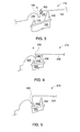
- FIG. 5 illustrates a flow control assembly 310 having a protrusion 350 that is positioned upstream of the rail member 332.
- the protrusions 450 and 550 may be angled in a downstream direction ⁇ 1 , which is illustrated in FIG. 6 , or in an upstream direction ⁇ 2 .
- a protrusion 650 may includes a flare F at a distal end 660 of the protrusion 650. The flare F may point in either or both of the upstream and downstream directions. While the embodiments of FIGS. 3-8 are illustrated separately, it is understood that the various embodiments may be provided in various combinations with one another and that other configurations in line with those described above are possible.
- FIG. 9 is an elevated perspective view of a portion of a turbine blade 720 having a flow diverting member 730 and a rail member 732.
- the turbine blade 720 includes a set of cooling passages 770 that extend longitudinally along the turbine blade 720.
- a cooling air A travels through the passages 770 and escape through a plurality of cooling holes 772 that are located on a surface 734 of the turbine blade 720.
- At least one of the cooling passages 770 are fluidly connected to a cooling hole 776 located in the rail member 732.
- the cooling hole 776 extends along a length L of the rail member 732, where the cooling air A may exit both ends 780 of the rail member 732.
- FIG. 10 is a top view of a turbine blade 820 having a flow diverting member 830 and a rail member 832.
- the turbine blade 820 also includes a top surface 834 where the flow diverting member 830 and the rail member 832 are located thereon.
- the turbine blade 820 also includes a tip portion 880.
- the tip portion 880 of the turbine blade represents an outer area or portion of the turbine blade 820.
- the rail member 832 provides support to the turbine blade 820 such that stress in the tip portion 880 is reduced when compared to a turbine blade that does not include a rail stiffener.
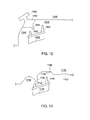
- the wall 922 is part of a non-axis-symmetric casing 948.
- a first chamber 1044 and a second chamber 1046 are located in a turbine casing 1048.
- a protrusion 1050 located between the first and second chambers 1044 and 1046 is created out of a single component, or by using multiple components assembled together.
- the protrusion 1020 is a separate removable piece 1090 assembled in a casing T-slot 1092. This configuration may be useful during upgrades of engine to incorporate chambers.
- the first chamber 1044 and the second chamber 1046 may be applied to new gas or steam turbines as well as turbines that are already operational. For operational turbines, the first chamber 1044 and the second chamber 1046 may be offered as part of a service package during upgrades.
- a casing 1148 and a flow diverting member 1130 of a turbine blade 1120 are provided.
- the flow diverting member 1130 is positioned such that the flow diverting member 1130 may be selectively deployed and makes contact against an abradable or a honeycomb surface 1122 of the casing 1148.
- the contact between the flow diverting member 1130 and the surface 1122 creates a groove shape 1180 in the casing 1148 in a second chamber 1146.
- the turbine blade 1120 rotates such that the flow diverting member 1130 may contact the surface 1122, thereby creating the groove 1180.
- the groove 1180 may further define a second chamber 1146 that is located in the casing 1148.
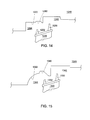
- FIG. 14 a casing 1248, a flow diverting member 1230, and a rail member 1232 of a turbine blade 1220 are provided.
- the rail member 1232 is positioned such that the rail member 1232 may be selectively deployed and makes contact against an abradable or a honeycomb surface 1222 of the casing 1248.
- the contact between the rail member 1232 and the surface 1222 creates a groove shape 1280 in the casing 1248 in a first chamber 1244 during operation.
- FIG. 15 is an illustration of yet another embodiment including a casing 1348, a flow diverting member 1330, and a rail member 1332 of a turbine blade 1320.
- the rail member 1332 is positioned such that the rail member 1332 may be selectively deployed and makes contact against an abradable or a honeycomb surface 1322 of the casing 1348.
- the surface 1322 and a first chamber 1344 includes a generally curved or concave configuration. The contact between the rail member 1332 and the surface 1322 creates a groove shape 1380 in the casing 1348 during operation.
Landscapes
- Engineering & Computer Science (AREA)
- Mechanical Engineering (AREA)
- General Engineering & Computer Science (AREA)
- Turbine Rotor Nozzle Sealing (AREA)
Abstract
Description
- The subject matter disclosed herein relates to a flow control assembly, and more specifically to a flow control assembly having a wall with first and second chambers, where the second chamber directs a fluid path into a vortex configuration.
- Generally, a turbine stage of a gas engine turbine includes a row of stationary vanes followed by a row of rotating blades in an annular turbine casing. The flow of fluid through the turbine casing is partially expanded in the stationary vanes and directed toward the rotating blades, and is further expanded to generate power. There is a physical clearance requirement between the tip of the rotating blade and an interior surface of the turbine casing to generally avoid interference between the blade and the turbine casing. Typically, turbine buckets are provided with a cover for improved aerodynamic and mechanical performance. A rail protruding out of the cover is used to reduce the physical clearance between the turbine casing and the rotating blade. The clearance requirement varies based on the dynamic and thermal behaviors of the rotor and the turbine casing.
- If the clearance requirement between the turbine casing and the rotating blade is relatively high, then a relatively high amount of high energy fluid flow is able to escape between the tip of the blade and the interior surface of the turbine casing without generating any useful power during turbine operations. The escaping high energy fluid flow constitutes tip clearance loss and can be one of the major sources of losses in the turbine stages. For example, in some cases, the tip clearance losses constitute 20-25% of the total losses in a turbine stage.
- Any reduction in the amount of tip clearance flow can result in a direct gain in power and performance of the turbine stage. Typically, such reductions can be achieved by reducing the physical clearance between the rotor tip and the turbine casing. This reduction, however, also increases the chance rubbing or interference between the rotating and stationary components. Another approach to reduce the tip clearance flow involves reducing the effective clearance between the rotor tip and casing by employing a duel vortex chamber in the turbine casing. However, this approach may be difficult to implement due to aerodynamic issues in the turbine.
- According to one aspect of the invention, a flow control assembly is provided, including a member and a wall. The member has a surface, a flow diverting member and a rail member. The rail member is situated upstream of the flow diverting member. The flow diverting member and the rail member each project from the surface of the member. The flow diverting member has a distal end. The wall is disposed in relation to the member to create a clearance gap between the distal end of the flow diverting member and the wall. A fluid path is created between the member and the wall, and flows from an upstream section and through the clearance gap. A first chamber and a second chamber are defined by the wall and located upstream of the clearance gap. The rail member diverts the fluid path in the first chamber into a generally curved configuration and the second chamber directs the fluid path into a vortex configuration.
- These and other advantages and features will become more apparent from the following description taken in conjunction with the drawings.
- Embodiments of the present invention will now be described, by way of example only, with reference to the accompanying drawings in which:
-
FIG. 1 is a side sectional view of a flow control assembly; -
FIG. 2 is an enlarged view of a flow diverting member shown inFIG. 1 ; -
FIG. 3 is a side sectional view of an alternative embodiment of the flow control assembly shown inFIG. 1 ; -
FIG. 4 is a side sectional view of another alternative embodiment of the flow control assembly shown inFIG. 1 ; -
FIG. 5 is a side sectional view of yet another alternative embodiment of the flow control assembly shown inFIG. 1 ; -
FIG. 6 is a side sectional view of an alternative embodiment of the flow control assembly shown inFIG. 1 ; -
FIG. 7 is a side sectional view of another alternative embodiment of the flow control assembly shown inFIG. 1 ; -
FIG. 8 is a side sectional view of yet another alternative embodiment of the flow control assembly shown inFIG. 1 ; -
FIG. 9 is an elevational view of another embodiment of the a turbine blade shown inFIG. 1 ; -
FIG. 10 is a top view of the turbine blade shown inFIG. 1 ; -
FIG. 11 is a side sectional view of an alternative embodiment of the flow control assembly shown inFIG. 1 ; -
FIG. 12 is a side sectional view of another alternative embodiment of the flow control assembly shown inFIG. 1 ; -
FIG. 13 is a side sectional view of yet another alternative embodiment of the flow control assembly shown inFIG. 1 ; -
FIG. 14 is a side sectional view of an alternative embodiment of the flow control assembly shown inFIG. 1 ; and -
FIG. 15 is a side sectional view of another alternative embodiment of the flow control assembly shown inFIG. 1 . - The detailed description explains embodiments of the invention, together with advantages and features, by way of example with reference to the drawings.
-
FIG. 1 is an illustration of an exemplaryflow control assembly 10. Theflow control assembly 10 includes amember 20 and awall 22. Themember 20 includes aflow diverting member 30 and arail member 32. Both theflow diverting member 30 and therail member 32 project outwardly from anouter surface 34 of themember 20, and towards thewall 22. Referring now to bothFIGS. 1-2 , thewall 22 is disposed in relation to adistal end 36 of themember 20 to create aclearance gap 38. Specifically,FIG. 2 illustrates that theclearance gap 38 includes an actual clearance gap A as well as an effective clearance gap E.A fluid path 40 is provided between themember 20 and thewall 22, where thefluid path 40 flows from anupstream section 42 and through theclearance gap 38. In one exemplary embodiment, theflow control assembly 10 may be employed in a gas turbine engine. For example, in one embodiment themember 20 may be a rotatable turbine blade and thewall 22 is part of aturbine casing 48 that perimetrically surrounds the turbine blade. - The
wall 22 includes afirst chamber 44 and asecond chamber 46. Both thefirst chamber 44 and thesecond chamber 46 are located upstream of theclearance gap 38, and thefirst chamber 44 is located upstream of thesecond chamber 46. Thefirst chamber 44 includes a generally curved or concave configuration. Aprotrusion 50 is located between the first andsecond chamber FIG. 1 , theprotrusion 50 is situated downstream of therail member 32 and upstream of theflow diverting member 30.FIG. 1 also illustrates thesecond chamber 46 transitioning from theprotrusion 50 in a generallyfilleted configuration 52. - The
fluid path 40 is directed to flow into the first andsecond chambers clearance gap 38. Specifically, therail member 32 is situated along theouter surface 34 of themember 20 to divert thefluid path 40 in thefirst chamber 44 into a generally curved configuration. Thefluid path 40 then flows around aprotrusion 50 that is located between thefirst chamber 44 and thesecond chamber 46. Thefluid path 40 then flows into thesecond chamber 46, where thefluid flow 40 is directed into a vortex configuration prior to flowing through theclearance gap 38. Because thefluid path 40 flows in the in generally curved configuration and the vortex configuration, the effective flow area E of thefluid path 40 through the actual clearance gap A is reduced such that E < A. That is, therail member 32 diverts thefluid path 40 in a curved configuration towards thewall 22 of thefirst chamber 44. Thesecond chamber 46 then allows for thefluid path 40 to flow in a vortex configuration, which causes thefluid path 40 to take a relativelysharp turn 54. In one embodiment, thesharp turn 54 may be about ninety degrees. Thefluid path 40 takes thesharp turn 54 and flows over theflow diverting member 30 such that thefluid path 40 is generally unable to flow through the entire thickness of the actual clearance gap A, which is shown inFIG. 2 . In a simulation, a typical turbine stage with first andsecond chambers - In the exemplary embodiment as shown in
FIG. 1 , therail member 32 includes a height X and theflow diverting member 30 includes a height of Y, where therail member 32 is about half the height of theflow diverting member 30. However, it is to be understood that other configurations of theflow diverting member 30 and the rail member may be used as well. For example, therail member 32 may increase in height such that the height X of therail member 32 is about equal to the height Y of theflow diverting member 30. - Although
FIG. 1 illustrates thesecond chamber 46 transitioning from theprotrusion 50 in a generally filletedconfiguration 52, it is understood that other configurations may be used as well. Specifically,FIG. 3 is an alternative embodiment of aflow control assembly 110. Theflow control assembly 110 includes amember 120 and awall 122, where themember 120 includes aflow diverting member 130 and arail member 132. Thewall 122 includes afirst chamber 144 and asecond chamber 146, and aprotrusion 150 situated downstream of therail member 132 and upstream of theflow diverting member 130. In the embodiment as shown inFIG. 3 , thesecond chamber 146 transitions from theprotrusion 150 in a generally angledconfiguration 152. Specifically, in the exemplary embodiment as shown, a substantially right angle A is situated between theprotrusion 150 and thesecond chamber 146. - Turing back to
FIG. 1 , in the embodiment as shown therail member 32 is generally aligned with a midpoint M of thefirst chamber 44. However, it is understood that therail member 32 may be positioned relative to therail member 32 in other configurations as well. For example, turning toFIG. 4 , aflow control assembly 210 is illustrated and includes amember 220 and awall 222, where themember 220 includes aflow diverting member 230 and arail member 232. Thewall 222 includes afirst chamber 244 and asecond chamber 246, and aprotrusion 250 situated downstream of therail member 232. Specifically, in the embodiment as shown inFIG. 4 , therail member 232 is positioned to be generally aligned with an end portion E of thefirst chamber 244. It should be noted that theprotrusion 250 may be positioned upstream of therail member 232 as well. For example,FIG. 5 illustrates aflow control assembly 310 having aprotrusion 350 that is positioned upstream of therail member 332. - In yet another embodiment as shown in
FIGS. 6-7 , theprotrusions FIG. 6 , or in an upstream direction θ2. In another embodiment as shown inFIG. 8 , aprotrusion 650 may includes a flare F at adistal end 660 of theprotrusion 650. The flare F may point in either or both of the upstream and downstream directions. While the embodiments ofFIGS. 3-8 are illustrated separately, it is understood that the various embodiments may be provided in various combinations with one another and that other configurations in line with those described above are possible. -
FIG. 9 is an elevated perspective view of a portion of a turbine blade 720 having aflow diverting member 730 and arail member 732. The turbine blade 720 includes a set of coolingpassages 770 that extend longitudinally along the turbine blade 720. A cooling air A travels through thepassages 770 and escape through a plurality ofcooling holes 772 that are located on asurface 734 of the turbine blade 720. At least one of thecooling passages 770 are fluidly connected to acooling hole 776 located in therail member 732. Specifically, in the embodiment as shown, thecooling hole 776 extends along a length L of therail member 732, where the cooling air A may exit both ends 780 of therail member 732. -
FIG. 10 is a top view of aturbine blade 820 having aflow diverting member 830 and arail member 832. Theturbine blade 820 also includes atop surface 834 where theflow diverting member 830 and therail member 832 are located thereon. Theturbine blade 820 also includes atip portion 880. Thetip portion 880 of the turbine blade represents an outer area or portion of theturbine blade 820. Therail member 832 provides support to theturbine blade 820 such that stress in thetip portion 880 is reduced when compared to a turbine blade that does not include a rail stiffener. - In one exemplary embodiment as shown in
FIG. 11 illustrating aturbine blade 920 and awall 922, thewall 922 is part of a non-axis-symmetric casing 948. In yet another embodiment as shown inFIG. 12 , afirst chamber 1044 and asecond chamber 1046 are located in aturbine casing 1048. Aprotrusion 1050 located between the first andsecond chambers FIG. 12 , theprotrusion 1020 is a separateremovable piece 1090 assembled in a casing T-slot 1092. This configuration may be useful during upgrades of engine to incorporate chambers. Thefirst chamber 1044 and thesecond chamber 1046 may be applied to new gas or steam turbines as well as turbines that are already operational. For operational turbines, thefirst chamber 1044 and thesecond chamber 1046 may be offered as part of a service package during upgrades. - In yet another embodiment as shown in
FIG. 13 , acasing 1148 and aflow diverting member 1130 of aturbine blade 1120 are provided. Theflow diverting member 1130 is positioned such that theflow diverting member 1130 may be selectively deployed and makes contact against an abradable or ahoneycomb surface 1122 of thecasing 1148. The contact between theflow diverting member 1130 and thesurface 1122 creates agroove shape 1180 in thecasing 1148 in asecond chamber 1146. Specifically, during operation of a turbine, theturbine blade 1120 rotates such that theflow diverting member 1130 may contact thesurface 1122, thereby creating thegroove 1180. Thegroove 1180 may further define asecond chamber 1146 that is located in thecasing 1148. - In still yet another embodiment as shown in
FIG. 14 , acasing 1248, aflow diverting member 1230, and arail member 1232 of aturbine blade 1220 are provided. Therail member 1232 is positioned such that therail member 1232 may be selectively deployed and makes contact against an abradable or ahoneycomb surface 1222 of thecasing 1248. The contact between therail member 1232 and thesurface 1222 creates agroove shape 1280 in thecasing 1248 in afirst chamber 1244 during operation.FIG. 15 is an illustration of yet another embodiment including acasing 1348, aflow diverting member 1330, and arail member 1332 of aturbine blade 1320. Therail member 1332 is positioned such that therail member 1332 may be selectively deployed and makes contact against an abradable or ahoneycomb surface 1322 of thecasing 1348. In the embodiment as shown inFIG. 15 , thesurface 1322 and afirst chamber 1344 includes a generally curved or concave configuration. The contact between therail member 1332 and thesurface 1322 creates agroove shape 1380 in thecasing 1348 during operation. - While the invention has been described in detail in connection with only a limited number of embodiments, it should be readily understood that the invention is not limited to such disclosed embodiments. Rather, the invention can be modified to incorporate any number of variations, alterations, substitutions or equivalent arrangements not heretofore described, but which are commensurate with the spirit and scope of the invention. Additionally, while various embodiments of the invention have been described, it is to be understood that aspects of the invention may include only some of the described embodiments. Accordingly, the invention is not to be seen as limited by the foregoing description, but is only limited by the scope of the appended claims.
Claims (15)
- A flow control assembly (10,110), comprising:a member (20,120) having a surface;a flow diverting member (30,130) and a rail member (32,132), the rail member (32,132) situated upstream of the flow diverting member (30,130), the flow diverting member (30,130) and the rail member (32,132) each projecting from the surface of the member (20,120), the flow diverting member (30,130) having a distal end (36);a wall (22,122) disposed in relation to the member (20,120) to create a clearance gap (38) between the distal end (36) of the flow diverting member (30,130) and the wall (22,122), a fluid path (40) created between the member (20) and the wall (22) and flowing from an upstream section (42) and through the clearance gap (38); anda first chamber (44,144) and a second chamber (46,146) defined by the wall (22,122) and located upstream of the clearance gap (38), the rail member (32,132) diverting the fluid path (40) in the first chamber (44,144) into a generally curved configuration and the second chamber (46,146) directing the fluid path (40) into a vortex configuration.
- The flow control assembly of claim 1, wherein the clearance gap (38) includes an actual clearance gap area (A) and an effective flow area (E), wherein the actual clearance gap area (A) is the distance between the wall (22,122) and the distal end (36) of the flow diverting member (30), and the effective flow area of the fluid path (40) through the actual clearance gap (A) is reduced such that the effective flow area (E) is less than the actual clearance gap (A).
- The flow control assembly of claim 1 or 2, wherein the first chamber (44,144) is disposed upstream of the second chamber (46,146), and wherein a protrusion (50,150) is created between the first chamber (44,144) and the second chamber (46,146).
- The flow control assembly of claim 3, wherein the second chamber (46) transitions from the protrusion (50) in a generally filleted configuration.
- The flow control assembly of claim 3, wherein the second chamber (146) transitions from the protrusion (150) in a generally angled configuration, wherein a substantially right angle is located between the second chamber (146) and the protrusion (150).
- The flow control assembly of any of claims 3 to 5, wherein the protrusion (250,350) is located one of upstream and downstream of the rail member (232,332).
- The flow control assembly of any of claims 3 to 6, wherein the protrusion (450,550) is angled in one of a downstream direction and an upstream direction.
- The flow control assembly of any of claims 3 to 7, wherein a distal end (660) of the protrusion (650) includes a flared configuration.
- The flow control assembly of any of claims 3 to 8, wherein the rail member (232) is positioned to be generally aligned with one of a midsection and an end portion of the first chamber (244).
- The flow control assembly of any of claims 1 to 9, wherein the rail member (732) includes at least one cooling hole (776) that is oriented in a lengthwise direction.
- The flow control assembly of any of claims 1 to 10, wherein the member (20) is a turbine blade (920), and the wall (922) is part of a turbine casing (948,1048) that perimetrically surrounds the turbine blade (920).
- The flow control assembly of claim 11, wherein the turbine casing (1048) includes a non-symmetric casing (948).
- The flow control assembly of any preceding claim, further comprising a removable member (1090) that is disposed between the first chamber (1044) and the second chamber (1046), wherein the removable member (1090) includes the protrusion.
- The flow control assembly of any preceding claim, wherein the wall (1148) includes at least one of an abradable and a honeycomb surface (1122), and wherein the flow diverting member (1130) creates a groove (1180) along a surface (1122) of the wall (1148).
- A turbine having the flow control assembly of any preceding claim, wherein the member (20) comprises:a turbine blade (920); andwherein the wall (22) comprises a turbine casing (948,1048).
Applications Claiming Priority (1)
| Application Number | Priority Date | Filing Date | Title |
|---|---|---|---|
| US13/248,139 US8807927B2 (en) | 2011-09-29 | 2011-09-29 | Clearance flow control assembly having rail member |
Publications (1)
| Publication Number | Publication Date |
|---|---|
| EP2574728A1 true EP2574728A1 (en) | 2013-04-03 |
Family
ID=46980808
Family Applications (1)
| Application Number | Title | Priority Date | Filing Date |
|---|---|---|---|
| EP12185988A Withdrawn EP2574728A1 (en) | 2011-09-29 | 2012-09-25 | Clearance flow control assembly having rail member and corresponding turbine |
Country Status (3)
| Country | Link |
|---|---|
| US (1) | US8807927B2 (en) |
| EP (1) | EP2574728A1 (en) |
| CN (1) | CN103032109A (en) |
Families Citing this family (10)
| Publication number | Priority date | Publication date | Assignee | Title |
|---|---|---|---|---|
| FR3001759B1 (en) * | 2013-02-07 | 2015-01-16 | Snecma | ROUGE AUBAGEE OF TURBOMACHINE |
| EP3060763B1 (en) * | 2013-10-21 | 2020-04-15 | United Technologies Corporation | Incident tolerant turbine vane gap flow discouragement |
| JP6131177B2 (en) * | 2013-12-03 | 2017-05-17 | 三菱重工業株式会社 | Seal structure and rotating machine |
| CN103806955A (en) * | 2014-02-25 | 2014-05-21 | 华电国际电力股份有限公司山东分公司 | Through-flow structure of steam turbine |
| CN104912604B (en) * | 2015-06-01 | 2016-08-24 | 西安交通大学 | A kind of have the spin-ended anti-rotating plate structure pressing down and bestirring oneself |
| CA2932601C (en) | 2015-06-17 | 2023-10-03 | Rolls-Royce Corporation | Labyrinth seal with tunable flow splitter |
| US10626739B2 (en) * | 2015-10-27 | 2020-04-21 | Mitsubishi Heavy Industries, Ltd. | Rotary machine |
| GB201519869D0 (en) * | 2015-11-11 | 2015-12-23 | Rolls Royce Plc | Shrouded turbine blade |
| FR3065483B1 (en) * | 2017-04-24 | 2020-08-07 | Safran Aircraft Engines | SEALING DEVICE BETWEEN ROTOR AND TURBOMACHINE STATOR |
| FR3068070B1 (en) * | 2017-06-26 | 2019-07-19 | Safran Aircraft Engines | TURBINE FOR TURBOMACHINE |
Citations (3)
| Publication number | Priority date | Publication date | Assignee | Title |
|---|---|---|---|---|
| EP1793086A2 (en) * | 2005-12-03 | 2007-06-06 | Rolls-Royce plc | Turbine blade |
| US20110070074A1 (en) * | 2009-09-24 | 2011-03-24 | Rolls-Royce Deutschland Ltd & Co Kg | Gas turbine with a shroud and labyrinth-type sealing arrangement |
| US20110085892A1 (en) * | 2009-10-14 | 2011-04-14 | General Electric Company | Vortex chambers for clearance flow control |
Family Cites Families (10)
| Publication number | Priority date | Publication date | Assignee | Title |
|---|---|---|---|---|
| BE533093A (en) * | 1953-11-12 | 1954-11-30 | ||
| US3897169A (en) * | 1973-04-19 | 1975-07-29 | Gen Electric | Leakage control structure |
| EP0924386B1 (en) * | 1997-12-23 | 2003-02-05 | ABB Turbo Systems AG | Method and device to seal off the space between a rotor and a stator |
| JP2002228014A (en) * | 2001-02-05 | 2002-08-14 | Mitsubishi Heavy Ind Ltd | Labyrinth seal |
| US7255531B2 (en) | 2003-12-17 | 2007-08-14 | Watson Cogeneration Company | Gas turbine tip shroud rails |
| US7445213B1 (en) * | 2006-06-14 | 2008-11-04 | Florida Turbine Technologies, Inc. | Stepped labyrinth seal |
| US8167547B2 (en) * | 2007-03-05 | 2012-05-01 | United Technologies Corporation | Gas turbine engine with canted pocket and canted knife edge seal |
| CH700686A1 (en) * | 2009-03-30 | 2010-09-30 | Alstom Technology Ltd | Blade for a gas turbine. |
| US8206082B2 (en) * | 2009-04-29 | 2012-06-26 | General Electric Company | Packing seal rotor lands |
| EP2390466B1 (en) * | 2010-05-27 | 2018-04-25 | Ansaldo Energia IP UK Limited | A cooling arrangement for a gas turbine |
-
2011
- 2011-09-29 US US13/248,139 patent/US8807927B2/en active Active
-
2012
- 2012-09-25 EP EP12185988A patent/EP2574728A1/en not_active Withdrawn
- 2012-09-27 CN CN 201210369355 patent/CN103032109A/en active Pending
Patent Citations (3)
| Publication number | Priority date | Publication date | Assignee | Title |
|---|---|---|---|---|
| EP1793086A2 (en) * | 2005-12-03 | 2007-06-06 | Rolls-Royce plc | Turbine blade |
| US20110070074A1 (en) * | 2009-09-24 | 2011-03-24 | Rolls-Royce Deutschland Ltd & Co Kg | Gas turbine with a shroud and labyrinth-type sealing arrangement |
| US20110085892A1 (en) * | 2009-10-14 | 2011-04-14 | General Electric Company | Vortex chambers for clearance flow control |
Also Published As
| Publication number | Publication date |
|---|---|
| CN103032109A (en) | 2013-04-10 |
| US8807927B2 (en) | 2014-08-19 |
| US20130084168A1 (en) | 2013-04-04 |
Similar Documents
| Publication | Publication Date | Title |
|---|---|---|
| US8807927B2 (en) | Clearance flow control assembly having rail member | |
| US8333557B2 (en) | Vortex chambers for clearance flow control | |
| EP3722556B1 (en) | Gas turbine section having a non-axisymmetric endwall contouring with aft mid-passage peak | |
| JP6514511B2 (en) | High-wing blade with two partial span shrouds and a curved dovetail | |
| CA2645778C (en) | Divergent turbine nozzle | |
| EP3722555B1 (en) | Turbine section having non-axisymmetric endwall contouring with forward mid-passage peak | |
| JP7237441B2 (en) | System for Cooling Seal Rails of Turbine Blade Tip Shrouds | |
| US10830082B2 (en) | Systems including rotor blade tips and circumferentially grooved shrouds | |
| CN103075198B (en) | Turbine bucket platform leading edge and associated method | |
| US10066488B2 (en) | Turbomachine blade with generally radial cooling conduit to wheel space | |
| US10590781B2 (en) | Turbine engine assembly with a component having a leading edge trough | |
| CA2647754A1 (en) | Turbine nozzle segment | |
| JP2012082826A (en) | Turbine bucket shroud tail | |
| CN105545376A (en) | Turbine assembly | |
| JP6496539B2 (en) | Method for cooling turbine bucket and turbine bucket of gas turbine engine | |
| US11549377B2 (en) | Airfoil with cooling hole | |
| CN106968721B (en) | Internal Cooling Configurations in Turbine Rotor Blades | |
| JP2013249835A (en) | Cooling assembly for bucket of turbine system and cooling method | |
| JP2011099438A (en) | Steampath flow separation reduction system | |
| JP6489823B2 (en) | Method for cooling turbine nozzles and turbine nozzles of gas turbine engines | |
| US10301967B2 (en) | Incident tolerant turbine vane gap flow discouragement | |
| US20180016915A1 (en) | Turbomachine component having a platform cavity with a stress reduction feature | |
| JP7130575B2 (en) | axial turbine |
Legal Events
| Date | Code | Title | Description |
|---|---|---|---|
| PUAI | Public reference made under article 153(3) epc to a published international application that has entered the european phase |
Free format text: ORIGINAL CODE: 0009012 |
|
| AK | Designated contracting states |
Kind code of ref document: A1 Designated state(s): AL AT BE BG CH CY CZ DE DK EE ES FI FR GB GR HR HU IE IS IT LI LT LU LV MC MK MT NL NO PL PT RO RS SE SI SK SM TR |
|
| AX | Request for extension of the european patent |
Extension state: BA ME |
|
| 17P | Request for examination filed |
Effective date: 20131004 |
|
| RBV | Designated contracting states (corrected) |
Designated state(s): AL AT BE BG CH CY CZ DE DK EE ES FI FR GB GR HR HU IE IS IT LI LT LU LV MC MK MT NL NO PL PT RO RS SE SI SK SM TR |
|
| STAA | Information on the status of an ep patent application or granted ep patent |
Free format text: STATUS: THE APPLICATION IS DEEMED TO BE WITHDRAWN |
|
| 18D | Application deemed to be withdrawn |
Effective date: 20150401 |