EP2574725A2 - Method for chemical milling an apparatus with a flow passage - Google Patents
Method for chemical milling an apparatus with a flow passage Download PDFInfo
- Publication number
- EP2574725A2 EP2574725A2 EP12177904A EP12177904A EP2574725A2 EP 2574725 A2 EP2574725 A2 EP 2574725A2 EP 12177904 A EP12177904 A EP 12177904A EP 12177904 A EP12177904 A EP 12177904A EP 2574725 A2 EP2574725 A2 EP 2574725A2
- Authority
- EP
- European Patent Office
- Prior art keywords
- preform
- flow
- flow area
- flow passage
- data
- Prior art date
- Legal status (The legal status is an assumption and is not a legal conclusion. Google has not performed a legal analysis and makes no representation as to the accuracy of the status listed.)
- Granted
Links
Images


Classifications
-
- F—MECHANICAL ENGINEERING; LIGHTING; HEATING; WEAPONS; BLASTING
- F01—MACHINES OR ENGINES IN GENERAL; ENGINE PLANTS IN GENERAL; STEAM ENGINES
- F01D—NON-POSITIVE DISPLACEMENT MACHINES OR ENGINES, e.g. STEAM TURBINES
- F01D9/00—Stators
- F01D9/02—Nozzles; Nozzle boxes; Stator blades; Guide conduits, e.g. individual nozzles
- F01D9/04—Nozzles; Nozzle boxes; Stator blades; Guide conduits, e.g. individual nozzles forming ring or sector
- F01D9/041—Nozzles; Nozzle boxes; Stator blades; Guide conduits, e.g. individual nozzles forming ring or sector using blades
-
- F—MECHANICAL ENGINEERING; LIGHTING; HEATING; WEAPONS; BLASTING
- F01—MACHINES OR ENGINES IN GENERAL; ENGINE PLANTS IN GENERAL; STEAM ENGINES
- F01D—NON-POSITIVE DISPLACEMENT MACHINES OR ENGINES, e.g. STEAM TURBINES
- F01D5/00—Blades; Blade-carrying members; Heating, heat-insulating, cooling or antivibration means on the blades or the members
- F01D5/12—Blades
- F01D5/14—Form or construction
- F01D5/141—Shape, i.e. outer, aerodynamic form
- F01D5/146—Shape, i.e. outer, aerodynamic form of blades with tandem configuration, split blades or slotted blades
-
- F—MECHANICAL ENGINEERING; LIGHTING; HEATING; WEAPONS; BLASTING
- F05—INDEXING SCHEMES RELATING TO ENGINES OR PUMPS IN VARIOUS SUBCLASSES OF CLASSES F01-F04
- F05D—INDEXING SCHEME FOR ASPECTS RELATING TO NON-POSITIVE-DISPLACEMENT MACHINES OR ENGINES, GAS-TURBINES OR JET-PROPULSION PLANTS
- F05D2230/00—Manufacture
- F05D2230/10—Manufacture by removing material
- F05D2230/11—Manufacture by removing material by electrochemical methods
Definitions
- the present invention relates to chemical milling and, in particular, to a method for chemical milling an apparatus with a flow passage based on flow area of the flow passage.
- Apparatus with flow passages may be utilized for various applications such as, for example, components for gas turbine engines.
- Gas turbine engine components may be manufactured using both casting and machining processes.
- a gas turbine engine duct blocker for example, may be cast and subsequently machined to provide the duct blocker with a predetermined geometry.
- a typical machining process may be time consuming, relatively expensive and leave the duct blocker with discontinuous surfaces.
- a method for manufacturing an apparatus with a flow passage includes providing a preform apparatus with a preform flow passage. Flow area of the preform flow passage is determined to provide determined flow area data. The determined flow area data is compared to reference flow area data to provide flow area comparison data. The preform apparatus is chemical milled based on the flow area comparison data.
- a method for manufacturing a gas turbine engine component with a flow passage includes forming a preform engine component with a preform flow passage. Flow area of the preform flow passage is determined, and compared to reference flow area. A chemical milling time is determined based on the comparison between the determined flow area and the reference flow area, and the preform engine component is chemical milled for the chemical milling time.
- the present invention includes a method for manufacturing an apparatus that includes a flow passage with a predetermined flow area.
- the method includes providing a preform apparatus that includes a preform flow passage.
- the preform apparatus and the preform flow passage may respectively have substantially the same geometrical configuration as the apparatus and the flow passage, however, for example, with one or more different dimensions.
- Flow area of the preform flow passage therefore is determined, and compared to a reference flow area that is indicative of the predetermined flow area. Based on this comparison, the preform apparatus is chemical milled to provide a milled apparatus that includes a milled flow passage with a milled flow area that is substantially equal to the reference flow area and, thus, the predetermined flow area.
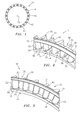
- FIG. 1 is a front view illustration of a rotational duct blocker 10 for a gas turbine engine that extends circumferentially around an axial centerline 12.
- FIG. 2 is a partial perspective illustration of the duct blocker 10 in a first configuration (e.g., an open configuration).
- FIG. 3 is a partial perspective illustration of the duct blocker 10 in a second configuration (e.g., a closed configuration).
- the duct blocker 10 includes an annular duct blocker rotor 14 and an annular duct blocker stator 16.
- the duct blocker rotor 14 includes an inner rotor platform 18, an outer rotor platform 20, a plurality of first vane segments 22 (e.g., leading edge vane segments), and a plurality of first flow apertures 24.
- the first vane segments 22 extend radially from the inner rotor platform 18 to the outer rotor platform 20.
- Each first vane segment 22 extends axially from a first vane edge 26 (e.g., a vane leading edge) to a first vane endwall 28.
- Each first flow aperture 24 extends circumferentially between respective adjacent first vane segments 22, and axially through the duct blocker rotor 14.
- the duct blocker stator 16 includes an inner stator platform 30, an outer stator platform 32, a plurality of second vane segments 34 (e.g., trailing edge vane segments), and a plurality of second flow apertures 36.
- the second vane segments 34 extend radially between the inner stator platform 30 and the outer stator platform 32.
- Each second vane segment 34 extends axially from a second vane endwall 38 to a second vane edge 40 (e.g., a vane trailing edge).
- Each second flow aperture 36 extends circumferentially between respective adjacent second vane segments 34, and axially through the duct blocker stator 16.
- the inner rotor platform 18 is arranged axially adjacent to the inner stator platform 30.
- the outer rotor platform 20 is arranged axially adjacent to the outer stator platform 32.
- the duct blocker rotor 14 rotates relative to the duct blocker stator 16. More particularly, the first vane segments 22 move circumferentially relative to the second vane segments 34 to regulate how much fluid may flow from the first flow apertures 24 to the second flow apertures 36.
- the first vane segments 22 may move, for example, between the first configuration (e.g., the open configuration) illustrated in FIG. 2 and the second configuration (e.g., the closed configuration) illustrated in FIG. 3 .
- first vane segments 22 and the second vane segments 34 are respectively circumferentially aligned and form a plurality of duct blocker vanes 42.
- Each duct blocker vane 42 may have an airfoil cross-sectional geometry that extends axially from the first vane edge 26 to the second vane edge 40.
- the first flow apertures 24 and the second flow apertures 36 are also respectively circumferentially aligned and form a plurality of sub-flow passages 44 that extend axially through the duct blocker 10.
- the sub-flow passages 44 collectively form a flow passage that has a first flow area in the first (e.g., open) configuration.
- first vane segments 22 are respectively circumferentially aligned with the second flow apertures 36.
- the first vane segments 22 therefore substantially restrict fluid flow through the flow passage to a second flow area in the second (e.g., closed) configuration that is substantially less than the first flow area.
- FIG. 4 is a flow diagram of a method for manufacturing the duct blocker illustrated in FIGS. 1-3 .
- a preform duct blocker 110 is cast, for example, as a unitary body.
- FIG. 5 is a partial perspective illustration of the preform duct blocker 110, which includes a plurality of preform vanes 142 and a plurality of preform sub-flow passages 144.
- the preform vanes 142 and the preform sub-flow passages 144 may have substantially the same geometrical configuration as the vanes 42 and the sub-flow passages 44 illustrated in FIG. 2 .
- the preform vanes 142 and the preform sub-flow passages 144 may have one or more different dimensions than the vanes 42 and the sub-flow passages 44 illustrated in FIG. 2 .
- Examples of methods for casting the preform duct blocker 110 may include investment casting (e.g., lost wax casting), sand casting, shell casting, die casting, etc.
- the preform duct blocker 110 may also be formed using methods such as forging, machining, etc.
- a first preform vane segment width 146 and a second preform vane segment width 148 may be measured for one or more of the preform vanes 142.
- the first preform vane segment width 146 extends circumferentially between a first side 150 and a second side 152 of a first preform vane endwall 128.
- the second preform vane segment width 148 extends circumferentially between a first side 154 and a second side 156 of a second preform vane segment endwall 138.
- an inner duct radius 158, an outer duct radius 160 and one or more fillet radiuses 162 may also be measured for one or more of the preform sub-flow passages 144.
- the inner duct radius 158 extends radially from an axial centerline of the preform duct blocker 110 to an outer radial surface 164 of a preform inner platform 166.
- the outer duct radius 160 extends radially from the axial centerline to an inner radial surface 168 of a preform outer platform 170.
- the aforesaid dimensions may be measured with, for example, a coordinate measuring machine, and provided to a processor as dimensional data. The dimensions may also be measured using other automated dimensional metrology machines (e.g., optical or laser non-contact measurement devices, etc.), or manually with, for example, a micrometer or caliper.
- the dimensional data is processed to determine flow area of the preform flow passage for a configuration where, for example, the preform duct blocker 110 is arranged in a second configuration (e.g., a closed configuration).
- the flow area may be determined, for example, by calculating an average flow area of the preform sub-flow passages 144, and multiplying the average flow area by the total number (N) of preform sub-flow passages 144 included in the preform duct blocker 110.
- Total Flow Area N ⁇ Avg .
- the Avg. Passage Height may be calculated by subtracting an average value (R 1 ) of the inner duct radiuses 158 from an average value (R 2 ) of the outer duct radiuses 160.
- the Avg. Fillet Radius is the average value of the fillet radiuses 162.
- determined flow area data is compared to (e.g., subtracted from) reference flow area data to provide flow area comparison data.
- the determined flow area data is indicative of the flow area of the preform flow passage determined in step 430.
- the reference flow area data is indicative of the second flow area of the flow passage illustrated in FIG. 3 , which may be provided by a part specification or standard.
- the flow area comparison data is processed to determine a chemical milling time.
- the chemical milling time is indicative of a quantity of time that the preform duct blocker 110 may be subjected to a chemical milling solution to increase its flow area, for example, to the second flow area set forth by the reference flow area data.
- the preform duct blocker 110 is chemical milled and, more particularly, subjected to (e.g., submersed in) a chemical milling solution for at least a portion of the chemical milling time.
- the chemical milling solution substantially uniformly removes material from exposed surfaces of the preform duct blocker 110, and may increase the flow area of the preform flow passage to the second flow area set forth by the reference flow area data.
- the chemical milling may also provide the preform duct blocker 110 with relatively smooth and continuous surfaces, and may remove alpha case where, for example, the preform duct blocker is constructed from titanium or titanium alloy.
- the milled preform duct blocker 110 is cut along a circumferential cut line 172 to provide a duct blocker rotor 114 and a duct blocker stator 116, which may have substantially the same geometry and dimensions as the duct blocker rotor 14 and the duct blocker stator 16 illustrated in FIGS. 2 and 3 .
- steps 420, 430, 440, 450 and 460 may be repeated one or more times on the milled preform duct blocker before step 470, for example, to ensure the flow area of the milled flow passage is substantially equal to the second flow area set forth by the reference flow area data.
- one or more portions of the preform duct blocker may be masked before step 460.
- one or more post chemical milling processes may be performed on the milled preform duct blocker 110.
- Examples of post chemical milling processes may include machining, additional chemical milling processes, etc.
- the Avg. Fillet Area may alternatively be calculated by multiplying the Avg. Fillet Radius by a predetermined correction factor.
- steps of the disclosed method may be performed automatically, for example, under the control of a processing device that executes program instructions. However, it is also contemplated that the steps may be performed by discrete devices.
Landscapes
- Engineering & Computer Science (AREA)
- Mechanical Engineering (AREA)
- General Engineering & Computer Science (AREA)
- Physics & Mathematics (AREA)
- Fluid Mechanics (AREA)
- Laser Beam Processing (AREA)
- Turbine Rotor Nozzle Sealing (AREA)
- General Factory Administration (AREA)
- Powder Metallurgy (AREA)
Abstract
Description
- The present invention relates to chemical milling and, in particular, to a method for chemical milling an apparatus with a flow passage based on flow area of the flow passage.
- Apparatus with flow passages may be utilized for various applications such as, for example, components for gas turbine engines. Gas turbine engine components may be manufactured using both casting and machining processes. A gas turbine engine duct blocker, for example, may be cast and subsequently machined to provide the duct blocker with a predetermined geometry. A typical machining process, however, may be time consuming, relatively expensive and leave the duct blocker with discontinuous surfaces.
- According to a first aspect of the invention, a method for manufacturing an apparatus with a flow passage includes providing a preform apparatus with a preform flow passage. Flow area of the preform flow passage is determined to provide determined flow area data. The determined flow area data is compared to reference flow area data to provide flow area comparison data. The preform apparatus is chemical milled based on the flow area comparison data.
- According to a second aspect of the invention, a method for manufacturing a gas turbine engine component with a flow passage includes forming a preform engine component with a preform flow passage. Flow area of the preform flow passage is determined, and compared to reference flow area. A chemical milling time is determined based on the comparison between the determined flow area and the reference flow area, and the preform engine component is chemical milled for the chemical milling time.
- The foregoing features and the operation of the invention will become more apparent in light of the following description and the accompanying drawings.
-
-
FIG. 1 is a front view illustration of a rotational duct blocker for a gas turbine engine; -
FIG. 2 is a partial perspective illustration of a rotational duct blocker in a first configuration; -
FIG. 3 is a partial perspective illustration of a rotational duct blocker in a second configuration; -
FIG. 4 is a flow diagram of a method for manufacturing a rotational duct blocker; -
FIG. 5 is a partial perspective illustration of a preform duct blocker; -
FIG. 6 is a partial sectional illustration of a vane included in the preform duct blocker illustrated inFIG. 5 ; and -
FIG. 7 is a partial cross-sectional illustration of the preform duct blocker illustrated inFIG. 5 . - The present invention includes a method for manufacturing an apparatus that includes a flow passage with a predetermined flow area. The method includes providing a preform apparatus that includes a preform flow passage. The preform apparatus and the preform flow passage may respectively have substantially the same geometrical configuration as the apparatus and the flow passage, however, for example, with one or more different dimensions. Flow area of the preform flow passage therefore is determined, and compared to a reference flow area that is indicative of the predetermined flow area. Based on this comparison, the preform apparatus is chemical milled to provide a milled apparatus that includes a milled flow passage with a milled flow area that is substantially equal to the reference flow area and, thus, the predetermined flow area.
- Apparatuses with flow passages may be utilized for various applications such as, for example, components for gas turbine engines.
FIG. 1 is a front view illustration of arotational duct blocker 10 for a gas turbine engine that extends circumferentially around anaxial centerline 12.FIG. 2 is a partial perspective illustration of theduct blocker 10 in a first configuration (e.g., an open configuration).FIG. 3 is a partial perspective illustration of theduct blocker 10 in a second configuration (e.g., a closed configuration). Referring toFIGS. 2 and 3 , theduct blocker 10 includes an annularduct blocker rotor 14 and an annularduct blocker stator 16. - The
duct blocker rotor 14 includes aninner rotor platform 18, anouter rotor platform 20, a plurality of first vane segments 22 (e.g., leading edge vane segments), and a plurality offirst flow apertures 24. Thefirst vane segments 22 extend radially from theinner rotor platform 18 to theouter rotor platform 20. Eachfirst vane segment 22 extends axially from a first vane edge 26 (e.g., a vane leading edge) to afirst vane endwall 28. Eachfirst flow aperture 24 extends circumferentially between respective adjacentfirst vane segments 22, and axially through theduct blocker rotor 14. - The
duct blocker stator 16 includes aninner stator platform 30, anouter stator platform 32, a plurality of second vane segments 34 (e.g., trailing edge vane segments), and a plurality ofsecond flow apertures 36. Thesecond vane segments 34 extend radially between theinner stator platform 30 and theouter stator platform 32. Eachsecond vane segment 34 extends axially from asecond vane endwall 38 to a second vane edge 40 (e.g., a vane trailing edge). Eachsecond flow aperture 36 extends circumferentially between respective adjacentsecond vane segments 34, and axially through theduct blocker stator 16. - The
inner rotor platform 18 is arranged axially adjacent to theinner stator platform 30. Theouter rotor platform 20 is arranged axially adjacent to theouter stator platform 32. - During engine operation, the
duct blocker rotor 14 rotates relative to theduct blocker stator 16. More particularly, thefirst vane segments 22 move circumferentially relative to thesecond vane segments 34 to regulate how much fluid may flow from thefirst flow apertures 24 to thesecond flow apertures 36. Thefirst vane segments 22 may move, for example, between the first configuration (e.g., the open configuration) illustrated inFIG. 2 and the second configuration (e.g., the closed configuration) illustrated inFIG. 3 . - In the first configuration (e.g., the open configuration) illustrated in
FIG. 2 , thefirst vane segments 22 and thesecond vane segments 34 are respectively circumferentially aligned and form a plurality ofduct blocker vanes 42. Eachduct blocker vane 42 may have an airfoil cross-sectional geometry that extends axially from thefirst vane edge 26 to thesecond vane edge 40. Thefirst flow apertures 24 and thesecond flow apertures 36 are also respectively circumferentially aligned and form a plurality ofsub-flow passages 44 that extend axially through theduct blocker 10. Thesub-flow passages 44 collectively form a flow passage that has a first flow area in the first (e.g., open) configuration. - In the second configuration (e.g., the closed configuration) illustrated in
FIG. 3 , thefirst vane segments 22 are respectively circumferentially aligned with thesecond flow apertures 36. Thefirst vane segments 22 therefore substantially restrict fluid flow through the flow passage to a second flow area in the second (e.g., closed) configuration that is substantially less than the first flow area. -
FIG. 4 is a flow diagram of a method for manufacturing the duct blocker illustrated inFIGS. 1-3 . Instep 410, apreform duct blocker 110 is cast, for example, as a unitary body.FIG. 5 is a partial perspective illustration of thepreform duct blocker 110, which includes a plurality ofpreform vanes 142 and a plurality ofpreform sub-flow passages 144. The preform vanes 142 and thepreform sub-flow passages 144 may have substantially the same geometrical configuration as thevanes 42 and thesub-flow passages 44 illustrated inFIG. 2 . The preform vanes 142 and thepreform sub-flow passages 144, however, may have one or more different dimensions than thevanes 42 and thesub-flow passages 44 illustrated inFIG. 2 . Examples of methods for casting thepreform duct blocker 110 may include investment casting (e.g., lost wax casting), sand casting, shell casting, die casting, etc. Thepreform duct blocker 110 may also be formed using methods such as forging, machining, etc. - In
step 420, one or more dimensions of thepreform duct blocker 110 are measured. Referring toFIG. 6 , for example, a first preformvane segment width 146 and a second preformvane segment width 148 may be measured for one or more of thepreform vanes 142. The first preformvane segment width 146 extends circumferentially between afirst side 150 and asecond side 152 of a firstpreform vane endwall 128. The second preformvane segment width 148 extends circumferentially between afirst side 154 and asecond side 156 of a second preformvane segment endwall 138. Referring now toFIG. 7 , aninner duct radius 158, anouter duct radius 160 and one ormore fillet radiuses 162 may also be measured for one or more of the preformsub-flow passages 144. Theinner duct radius 158 extends radially from an axial centerline of thepreform duct blocker 110 to an outerradial surface 164 of a preforminner platform 166. Theouter duct radius 160 extends radially from the axial centerline to an innerradial surface 168 of a preformouter platform 170. The aforesaid dimensions may be measured with, for example, a coordinate measuring machine, and provided to a processor as dimensional data. The dimensions may also be measured using other automated dimensional metrology machines (e.g., optical or laser non-contact measurement devices, etc.), or manually with, for example, a micrometer or caliper. - In
step 430, the dimensional data is processed to determine flow area of the preform flow passage for a configuration where, for example, thepreform duct blocker 110 is arranged in a second configuration (e.g., a closed configuration). The flow area may be determined, for example, by calculating an average flow area of the preformsub-flow passages 144, and multiplying the average flow area by the total number (N) of preformsub-flow passages 144 included in thepreform duct blocker 110.
- The average flow area may be calculated with, for example, the following expressions:


- The Avg. Passage Height may be calculated by subtracting an average value (R1) of the inner duct radiuses 158 from an average value (R2) of the outer duct radiuses 160. The Avg. Passage Width may be calculated for the second (e.g., closed) configuration, for example, with the following expression:

where W1 is an average value of the first preformvane segment widths 146, and W2 is an average value of the second preformvane segment widths 148. The Avg. Fillet Radius is the average value of the fillet radiuses 162. - In
step 440, determined flow area data is compared to (e.g., subtracted from) reference flow area data to provide flow area comparison data. The determined flow area data is indicative of the flow area of the preform flow passage determined instep 430. The reference flow area data is indicative of the second flow area of the flow passage illustrated inFIG. 3 , which may be provided by a part specification or standard. - In
step 450, the flow area comparison data is processed to determine a chemical milling time. The chemical milling time is indicative of a quantity of time that thepreform duct blocker 110 may be subjected to a chemical milling solution to increase its flow area, for example, to the second flow area set forth by the reference flow area data. - In
step 460, thepreform duct blocker 110 is chemical milled and, more particularly, subjected to (e.g., submersed in) a chemical milling solution for at least a portion of the chemical milling time. The chemical milling solution substantially uniformly removes material from exposed surfaces of thepreform duct blocker 110, and may increase the flow area of the preform flow passage to the second flow area set forth by the reference flow area data. The chemical milling may also provide thepreform duct blocker 110 with relatively smooth and continuous surfaces, and may remove alpha case where, for example, the preform duct blocker is constructed from titanium or titanium alloy. - Referring to
FIGS. 4 and6 , instep 470, the milledpreform duct blocker 110 is cut along acircumferential cut line 172 to provide aduct blocker rotor 114 and aduct blocker stator 116, which may have substantially the same geometry and dimensions as theduct blocker rotor 14 and theduct blocker stator 16 illustrated inFIGS. 2 and 3 . - In some embodiments,
steps step 470, for example, to ensure the flow area of the milled flow passage is substantially equal to the second flow area set forth by the reference flow area data. - In some embodiments, one or more portions of the preform duct blocker may be masked before
step 460. - In some embodiments, one or more post chemical milling processes may be performed on the milled
preform duct blocker 110. Examples of post chemical milling processes may include machining, additional chemical milling processes, etc. - In some embodiments, the Avg. Fillet Area may alternatively be calculated by multiplying the Avg. Fillet Radius by a predetermined correction factor.
- One of ordinary skill in the art will appreciate that the steps of the disclosed method may be performed automatically, for example, under the control of a processing device that executes program instructions. However, it is also contemplated that the steps may be performed by discrete devices.
- While various embodiments of the present invention have been disclosed, it will be apparent to those of ordinary skill in the art that many more embodiments and implementations are possible within the scope of the invention. Accordingly, the present invention is not to be restricted except in light of the attached claims and their equivalents.
Claims (15)
- A method for manufacturing an apparatus (10) comprising a flow passage (44), comprising:providing a preform apparatus (110) comprising a preform flow passage (144);determining flow area of the preform flow passage (144) to provide determined flow area data;comparing the determined flow area data to reference flow area data to provide flow area comparison data; andchemical milling the preform apparatus (110) based on the flow area comparison data.
- The method of claim 1, comprising casting the perform apparatus (110).
- The method of claim 1 or 2, further comprising determining a chemical milling time based on the flow area comparison data, wherein the chemical milling of the preform apparatus (110) comprises applying a chemical milling solution to the preform apparatus (110) for the chemical milling time.
- The method of any of claims 1 to 3, comprising measuring dimensions of the preform apparatus (110) with a coordinate measuring machine to provide dimensional data, wherein the flow area of the preform flow passage (144) is determined by processing the dimensional data.
- The method of any preceding claim, wherein the preform flow passage (144) comprises a plurality of preform sub-flow passages, and optionally wherein the preform apparatus (110) further comprises a plurality of preform vanes (142), and wherein a first of the plurality of the preform sub-flow passages (144) extends between respective adjacent preform vanes (142).
- The method of claim 5, further comprising measuring dimensions of the preform vanes (142) and/or the preform sub-flow passages (144) to provide dimensional data, wherein the flow area of the preform flow passage (144) is determined by processing the dimensional data.
- The method of any preceding claim, wherein the apparatus (10) comprises a duct blocker rotor (14) that rotates relative to a duct blocker stator (15) between a first configuration and a second configuration, wherein the flow passage (44) comprises a first flow area in the first configuration, and wherein the flow passage (44) comprises a second flow area in the second configuration that is less than the first flow area.
- The method of claim 7, wherein the flow area of the preform flow passage (144) is determined for when the duct blocker rotor (14) and the duct blocker stator (16) are in the second configuration, and optionally further comprises measuring dimensions of the preform sub-flow passages (144) and the preform vanes (142), and averaging the respective dimensions to provide dimensional data, wherein the flow area of the preform flow passage (144) is determined by processing the dimensional data.
- The method of claim 7 or 8, further comprising cutting the milled preform apparatus (110) to provide the duct blocker rotor (14) and the duct blocker stator (16).
- The method of any preceding claim, wherein the apparatus (10) comprises a gas turbine engine component.
- The method of any preceding claim, further comprising:determining flow area of the milled preform flow passage (144) to provide second determined flow area data;comparing the second determined flow area data to the reference flow area data to provide second flow area comparison data; andchemical milling the milled preform apparatus (110) based on the second flow area comparison data.
- The method of any preceding claim, further comprising masking a portion of the preform apparatus (10).
- A method for manufacturing a gas turbine engine component (110) comprising a flow passage (44), comprising:forming a preform engine component (110) comprising a preform flow passage (144);determining flow area of the preform flow passage (144);comparing the determined flow area of the preform flow passage (144) to a reference flow area, and determining a chemical milling time based on the comparison; andchemical milling the preform engine component (110) for the chemical milling time.
- The method of claim 13, wherein:the preform engine component (110) is formed through casting; and/orthe preform flow passage (144) comprises a plurality of preform sub-flow passages.
- The method of claim 13 or 14, further comprising measuring dimensions of the preform engine component (110) and/or the preform flow passage (144) to provide dimensional data, wherein the flow area of the preform flow passage (144) is determined by processing the dimensional data.
Applications Claiming Priority (1)
| Application Number | Priority Date | Filing Date | Title |
|---|---|---|---|
| US13/250,230 US8707799B2 (en) | 2011-09-30 | 2011-09-30 | Method for chemical milling an apparatus with a flow passage |
Publications (4)
| Publication Number | Publication Date |
|---|---|
| EP2574725A2 true EP2574725A2 (en) | 2013-04-03 |
| EP2574725A3 EP2574725A3 (en) | 2017-04-12 |
| EP2574725B1 EP2574725B1 (en) | 2021-03-17 |
| EP2574725B8 EP2574725B8 (en) | 2021-04-21 |
Family
ID=46758613
Family Applications (1)
| Application Number | Title | Priority Date | Filing Date |
|---|---|---|---|
| EP12177904.5A Not-in-force EP2574725B8 (en) | 2011-09-30 | 2012-07-25 | Method for chemical milling a gas turbine engine component with a flow passage |
Country Status (2)
| Country | Link |
|---|---|
| US (1) | US8707799B2 (en) |
| EP (1) | EP2574725B8 (en) |
Families Citing this family (2)
| Publication number | Priority date | Publication date | Assignee | Title |
|---|---|---|---|---|
| US9011082B2 (en) * | 2011-12-22 | 2015-04-21 | United Technologies Corporation | Gas turbine engine duct blocker with rotatable vane segments |
| US11021958B2 (en) * | 2018-10-31 | 2021-06-01 | Raytheon Technologies Corporation | Split vernier ring for turbine rotor stack assembly |
Family Cites Families (22)
| Publication number | Priority date | Publication date | Assignee | Title |
|---|---|---|---|---|
| US3108435A (en) * | 1955-03-14 | 1963-10-29 | Chandler Evans Corp | Fuel control system |
| US4900398A (en) | 1989-06-19 | 1990-02-13 | General Motors Corporation | Chemical milling of titanium |
| US5186790A (en) | 1990-11-13 | 1993-02-16 | Aluminum Company Of America | Chemical milling of aluminum-lithium alloys |
| US5217569A (en) | 1991-01-07 | 1993-06-08 | United Technologies Corporation | Chemical milling solution for reduced hydrogen absorption |
| US5248386A (en) * | 1991-02-08 | 1993-09-28 | Aluminum Company Of America | Milling solution and method |
| US5391256A (en) | 1993-04-05 | 1995-02-21 | General Electric Company | Hollow airfoil cavity surface texture enhancement |
| US5408747A (en) * | 1994-04-14 | 1995-04-25 | United Technologies Corporation | Compact radial-inflow turbines |
| AUPM647094A0 (en) | 1994-06-27 | 1994-07-21 | Melanesia International Trust Company Limited | Chemical milling apparatus and method |
| DE4425344C2 (en) * | 1994-07-18 | 2001-05-23 | Abb Patent Gmbh | Rotary vane with at least one axial needle slewing ring as a rotatable bearing element |
| GB9805422D0 (en) * | 1998-03-13 | 1998-05-06 | Standard Aero Limited | Gas flow area measurement |
| US6294072B1 (en) | 1999-09-20 | 2001-09-25 | Aeromet Technologies, Inc. | Removal of metal oxide scale from metal products |
| US6793838B2 (en) | 2001-09-28 | 2004-09-21 | United Technologies Corporation | Chemical milling process and solution for cast titanium alloys |
| US6754954B1 (en) | 2003-07-08 | 2004-06-29 | Borgwarner Inc. | Process for manufacturing forged titanium compressor wheel |
| US6991425B2 (en) | 2003-09-12 | 2006-01-31 | Honeywell International, Inc. | Air turbine starter with unitary inlet and stator |
| US7097421B2 (en) * | 2004-10-08 | 2006-08-29 | United Technologies Corporation | Vernier duct blocker |
| US7784183B2 (en) * | 2005-06-09 | 2010-08-31 | General Electric Company | System and method for adjusting performance of manufacturing operations or steps |
| US7871242B2 (en) * | 2007-05-31 | 2011-01-18 | United Technologies Corporation | Single actuator controlled rotational flow balance system |
| US8206102B2 (en) * | 2007-08-16 | 2012-06-26 | United Technologies Corporation | Attachment interface for a gas turbine engine composite duct structure |
| US7976754B2 (en) * | 2007-08-29 | 2011-07-12 | Inergy Automotive Systems Research (S.A.) | Process for manufacturing a plastic hollow body, device and equipment for the implementation thereof |
| EP2177298A1 (en) * | 2008-10-20 | 2010-04-21 | Sulzer Markets and Technology AG | Manufacturing procedure for closed discs |
| FR2939130B1 (en) * | 2008-11-28 | 2011-09-16 | Snecma Propulsion Solide | PROCESS FOR MANUFACTURING COMPOUND FORM SHAPE PIECE OF COMPOSITE MATERIAL |
| US8931601B2 (en) * | 2010-11-05 | 2015-01-13 | United Technologies Corporation | Dampening device |
-
2011
- 2011-09-30 US US13/250,230 patent/US8707799B2/en active Active
-
2012
- 2012-07-25 EP EP12177904.5A patent/EP2574725B8/en not_active Not-in-force
Non-Patent Citations (1)
| Title |
|---|
| None |
Also Published As
| Publication number | Publication date |
|---|---|
| EP2574725B8 (en) | 2021-04-21 |
| EP2574725A3 (en) | 2017-04-12 |
| EP2574725B1 (en) | 2021-03-17 |
| US20130085592A1 (en) | 2013-04-04 |
| US8707799B2 (en) | 2014-04-29 |
Similar Documents
| Publication | Publication Date | Title |
|---|---|---|
| EP2070619B1 (en) | Method of machining a turbine disk | |
| CN103375181B (en) | Turbine assembly | |
| KR20120034799A (en) | Automated repair method and system | |
| CN107366576B (en) | A processing and detection device and method for engine oil supply support plate casing | |
| US9327341B2 (en) | Method of fabricating integrally bladed rotor and stator vane assembly | |
| US10704399B2 (en) | Adaptively opening cooling pathway | |
| US20190210111A1 (en) | Shrouded rotor and a hybrid additive manufacturing process for a shrouded rotor | |
| EP3255517A1 (en) | A method of manufacturing and inspecting gas washed components in a gas turbine engine | |
| EP3255518A1 (en) | A method of manufacturing and inspecting gas washed components in a gas turbine engine | |
| US20150354374A1 (en) | Turbine blisk and method of manufacturing thereof | |
| EP3551852B1 (en) | Adaptive machining of cooled turbine airfoil | |
| EP2574725B1 (en) | Method for chemical milling a gas turbine engine component with a flow passage | |
| EP3441181A1 (en) | Methods for treating components formed from equiaxed material or directionally solidified structure, and treated components | |
| US8646511B2 (en) | Component with inspection-facilitating features | |
| US10760433B2 (en) | Method for inspecting a rotor blade unit | |
| US11066942B2 (en) | Systems and method for determining turbine assembly flow characteristics | |
| CN113748310B (en) | Method for dimensional inspection of turbine components | |
| EP3434864B1 (en) | A method and system for repairing a turbomachine | |
| JP5517587B2 (en) | Intermediate processed product of gas turbine blade, gas turbine blade and gas turbine, manufacturing method of intermediate processed product of gas turbine blade, and manufacturing method of gas turbine blade | |
| GB2428396A (en) | A method of manufacturing an article with a reference datum feature |
Legal Events
| Date | Code | Title | Description |
|---|---|---|---|
| PUAI | Public reference made under article 153(3) epc to a published international application that has entered the european phase |
Free format text: ORIGINAL CODE: 0009012 |
|
| AK | Designated contracting states |
Kind code of ref document: A2 Designated state(s): AL AT BE BG CH CY CZ DE DK EE ES FI FR GB GR HR HU IE IS IT LI LT LU LV MC MK MT NL NO PL PT RO RS SE SI SK SM TR |
|
| AX | Request for extension of the european patent |
Extension state: BA ME |
|
| RAP1 | Party data changed (applicant data changed or rights of an application transferred) |
Owner name: UNITED TECHNOLOGIES CORPORATION |
|
| PUAL | Search report despatched |
Free format text: ORIGINAL CODE: 0009013 |
|
| AK | Designated contracting states |
Kind code of ref document: A3 Designated state(s): AL AT BE BG CH CY CZ DE DK EE ES FI FR GB GR HR HU IE IS IT LI LT LU LV MC MK MT NL NO PL PT RO RS SE SI SK SM TR |
|
| AX | Request for extension of the european patent |
Extension state: BA ME |
|
| RIC1 | Information provided on ipc code assigned before grant |
Ipc: B23P 15/00 20060101ALI20170309BHEP Ipc: F01D 5/14 20060101AFI20170309BHEP Ipc: C23F 1/04 20060101ALI20170309BHEP Ipc: F01D 9/04 20060101ALI20170309BHEP Ipc: B23C 3/18 20060101ALI20170309BHEP |
|
| STAA | Information on the status of an ep patent application or granted ep patent |
Free format text: STATUS: REQUEST FOR EXAMINATION WAS MADE |
|
| 17P | Request for examination filed |
Effective date: 20171012 |
|
| RBV | Designated contracting states (corrected) |
Designated state(s): AL AT BE BG CH CY CZ DE DK EE ES FI FR GB GR HR HU IE IS IT LI LT LU LV MC MK MT NL NO PL PT RO RS SE SI SK SM TR |
|
| GRAP | Despatch of communication of intention to grant a patent |
Free format text: ORIGINAL CODE: EPIDOSNIGR1 |
|
| STAA | Information on the status of an ep patent application or granted ep patent |
Free format text: STATUS: GRANT OF PATENT IS INTENDED |
|
| INTG | Intention to grant announced |
Effective date: 20191010 |
|
| GRAJ | Information related to disapproval of communication of intention to grant by the applicant or resumption of examination proceedings by the epo deleted |
Free format text: ORIGINAL CODE: EPIDOSDIGR1 |
|
| STAA | Information on the status of an ep patent application or granted ep patent |
Free format text: STATUS: REQUEST FOR EXAMINATION WAS MADE |
|
| INTC | Intention to grant announced (deleted) | ||
| STAA | Information on the status of an ep patent application or granted ep patent |
Free format text: STATUS: EXAMINATION IS IN PROGRESS |
|
| 17Q | First examination report despatched |
Effective date: 20200409 |
|
| GRAP | Despatch of communication of intention to grant a patent |
Free format text: ORIGINAL CODE: EPIDOSNIGR1 |
|
| STAA | Information on the status of an ep patent application or granted ep patent |
Free format text: STATUS: GRANT OF PATENT IS INTENDED |
|
| INTG | Intention to grant announced |
Effective date: 20201005 |
|
| GRAS | Grant fee paid |
Free format text: ORIGINAL CODE: EPIDOSNIGR3 |
|
| GRAA | (expected) grant |
Free format text: ORIGINAL CODE: 0009210 |
|
| STAA | Information on the status of an ep patent application or granted ep patent |
Free format text: STATUS: THE PATENT HAS BEEN GRANTED |
|
| REG | Reference to a national code |
Ref country code: DE Ref legal event code: R081 Ref document number: 602012074803 Country of ref document: DE Owner name: RAYTHEON TECHNOLOGIES CORPORATION, FARMINGTON, US Free format text: FORMER OWNER: UNITED TECHNOLOGIES CORPORATION, FARMINGTON, CONN., US |
|
| AK | Designated contracting states |
Kind code of ref document: B1 Designated state(s): AL AT BE BG CH CY CZ DE DK EE ES FI FR GB GR HR HU IE IS IT LI LT LU LV MC MK MT NL NO PL PT RO RS SE SI SK SM TR |
|
| REG | Reference to a national code |
Ref country code: GB Ref legal event code: FG4D |
|
| RAP2 | Party data changed (patent owner data changed or rights of a patent transferred) |
Owner name: RAYTHEON TECHNOLOGIES CORPORATION |
|
| REG | Reference to a national code |
Ref country code: CH Ref legal event code: PK Free format text: BERICHTIGUNG B8 Ref country code: CH Ref legal event code: EP |
|
| REG | Reference to a national code |
Ref country code: DE Ref legal event code: R096 Ref document number: 602012074803 Country of ref document: DE |
|
| REG | Reference to a national code |
Ref country code: IE Ref legal event code: FG4D |
|
| REG | Reference to a national code |
Ref country code: AT Ref legal event code: REF Ref document number: 1372403 Country of ref document: AT Kind code of ref document: T Effective date: 20210415 |
|
| REG | Reference to a national code |
Ref country code: LT Ref legal event code: MG9D |
|
| PG25 | Lapsed in a contracting state [announced via postgrant information from national office to epo] |
Ref country code: HR Free format text: LAPSE BECAUSE OF FAILURE TO SUBMIT A TRANSLATION OF THE DESCRIPTION OR TO PAY THE FEE WITHIN THE PRESCRIBED TIME-LIMIT Effective date: 20210317 Ref country code: FI Free format text: LAPSE BECAUSE OF FAILURE TO SUBMIT A TRANSLATION OF THE DESCRIPTION OR TO PAY THE FEE WITHIN THE PRESCRIBED TIME-LIMIT Effective date: 20210317 Ref country code: GR Free format text: LAPSE BECAUSE OF FAILURE TO SUBMIT A TRANSLATION OF THE DESCRIPTION OR TO PAY THE FEE WITHIN THE PRESCRIBED TIME-LIMIT Effective date: 20210618 Ref country code: NO Free format text: LAPSE BECAUSE OF FAILURE TO SUBMIT A TRANSLATION OF THE DESCRIPTION OR TO PAY THE FEE WITHIN THE PRESCRIBED TIME-LIMIT Effective date: 20210617 Ref country code: BG Free format text: LAPSE BECAUSE OF FAILURE TO SUBMIT A TRANSLATION OF THE DESCRIPTION OR TO PAY THE FEE WITHIN THE PRESCRIBED TIME-LIMIT Effective date: 20210617 |
|
| REG | Reference to a national code |
Ref country code: AT Ref legal event code: MK05 Ref document number: 1372403 Country of ref document: AT Kind code of ref document: T Effective date: 20210317 |
|
| REG | Reference to a national code |
Ref country code: NL Ref legal event code: MP Effective date: 20210317 |
|
| PG25 | Lapsed in a contracting state [announced via postgrant information from national office to epo] |
Ref country code: SE Free format text: LAPSE BECAUSE OF FAILURE TO SUBMIT A TRANSLATION OF THE DESCRIPTION OR TO PAY THE FEE WITHIN THE PRESCRIBED TIME-LIMIT Effective date: 20210317 Ref country code: RS Free format text: LAPSE BECAUSE OF FAILURE TO SUBMIT A TRANSLATION OF THE DESCRIPTION OR TO PAY THE FEE WITHIN THE PRESCRIBED TIME-LIMIT Effective date: 20210317 Ref country code: LV Free format text: LAPSE BECAUSE OF FAILURE TO SUBMIT A TRANSLATION OF THE DESCRIPTION OR TO PAY THE FEE WITHIN THE PRESCRIBED TIME-LIMIT Effective date: 20210317 |
|
| PG25 | Lapsed in a contracting state [announced via postgrant information from national office to epo] |
Ref country code: NL Free format text: LAPSE BECAUSE OF FAILURE TO SUBMIT A TRANSLATION OF THE DESCRIPTION OR TO PAY THE FEE WITHIN THE PRESCRIBED TIME-LIMIT Effective date: 20210317 |
|
| PG25 | Lapsed in a contracting state [announced via postgrant information from national office to epo] |
Ref country code: SM Free format text: LAPSE BECAUSE OF FAILURE TO SUBMIT A TRANSLATION OF THE DESCRIPTION OR TO PAY THE FEE WITHIN THE PRESCRIBED TIME-LIMIT Effective date: 20210317 Ref country code: AT Free format text: LAPSE BECAUSE OF FAILURE TO SUBMIT A TRANSLATION OF THE DESCRIPTION OR TO PAY THE FEE WITHIN THE PRESCRIBED TIME-LIMIT Effective date: 20210317 Ref country code: EE Free format text: LAPSE BECAUSE OF FAILURE TO SUBMIT A TRANSLATION OF THE DESCRIPTION OR TO PAY THE FEE WITHIN THE PRESCRIBED TIME-LIMIT Effective date: 20210317 Ref country code: CZ Free format text: LAPSE BECAUSE OF FAILURE TO SUBMIT A TRANSLATION OF THE DESCRIPTION OR TO PAY THE FEE WITHIN THE PRESCRIBED TIME-LIMIT Effective date: 20210317 Ref country code: LT Free format text: LAPSE BECAUSE OF FAILURE TO SUBMIT A TRANSLATION OF THE DESCRIPTION OR TO PAY THE FEE WITHIN THE PRESCRIBED TIME-LIMIT Effective date: 20210317 |
|
| PG25 | Lapsed in a contracting state [announced via postgrant information from national office to epo] |
Ref country code: PL Free format text: LAPSE BECAUSE OF FAILURE TO SUBMIT A TRANSLATION OF THE DESCRIPTION OR TO PAY THE FEE WITHIN THE PRESCRIBED TIME-LIMIT Effective date: 20210317 Ref country code: PT Free format text: LAPSE BECAUSE OF FAILURE TO SUBMIT A TRANSLATION OF THE DESCRIPTION OR TO PAY THE FEE WITHIN THE PRESCRIBED TIME-LIMIT Effective date: 20210719 Ref country code: ES Free format text: LAPSE BECAUSE OF FAILURE TO SUBMIT A TRANSLATION OF THE DESCRIPTION OR TO PAY THE FEE WITHIN THE PRESCRIBED TIME-LIMIT Effective date: 20210317 Ref country code: SK Free format text: LAPSE BECAUSE OF FAILURE TO SUBMIT A TRANSLATION OF THE DESCRIPTION OR TO PAY THE FEE WITHIN THE PRESCRIBED TIME-LIMIT Effective date: 20210317 Ref country code: RO Free format text: LAPSE BECAUSE OF FAILURE TO SUBMIT A TRANSLATION OF THE DESCRIPTION OR TO PAY THE FEE WITHIN THE PRESCRIBED TIME-LIMIT Effective date: 20210317 Ref country code: IS Free format text: LAPSE BECAUSE OF FAILURE TO SUBMIT A TRANSLATION OF THE DESCRIPTION OR TO PAY THE FEE WITHIN THE PRESCRIBED TIME-LIMIT Effective date: 20210717 |
|
| REG | Reference to a national code |
Ref country code: DE Ref legal event code: R097 Ref document number: 602012074803 Country of ref document: DE |
|
| PLBE | No opposition filed within time limit |
Free format text: ORIGINAL CODE: 0009261 |
|
| STAA | Information on the status of an ep patent application or granted ep patent |
Free format text: STATUS: NO OPPOSITION FILED WITHIN TIME LIMIT |
|
| PG25 | Lapsed in a contracting state [announced via postgrant information from national office to epo] |
Ref country code: DK Free format text: LAPSE BECAUSE OF FAILURE TO SUBMIT A TRANSLATION OF THE DESCRIPTION OR TO PAY THE FEE WITHIN THE PRESCRIBED TIME-LIMIT Effective date: 20210317 Ref country code: AL Free format text: LAPSE BECAUSE OF FAILURE TO SUBMIT A TRANSLATION OF THE DESCRIPTION OR TO PAY THE FEE WITHIN THE PRESCRIBED TIME-LIMIT Effective date: 20210317 |
|
| 26N | No opposition filed |
Effective date: 20211220 |
|
| PG25 | Lapsed in a contracting state [announced via postgrant information from national office to epo] |
Ref country code: SI Free format text: LAPSE BECAUSE OF FAILURE TO SUBMIT A TRANSLATION OF THE DESCRIPTION OR TO PAY THE FEE WITHIN THE PRESCRIBED TIME-LIMIT Effective date: 20210317 |
|
| REG | Reference to a national code |
Ref country code: CH Ref legal event code: PL |
|
| PG25 | Lapsed in a contracting state [announced via postgrant information from national office to epo] |
Ref country code: MC Free format text: LAPSE BECAUSE OF FAILURE TO SUBMIT A TRANSLATION OF THE DESCRIPTION OR TO PAY THE FEE WITHIN THE PRESCRIBED TIME-LIMIT Effective date: 20210317 |
|
| REG | Reference to a national code |
Ref country code: BE Ref legal event code: MM Effective date: 20210731 |
|
| PG25 | Lapsed in a contracting state [announced via postgrant information from national office to epo] |
Ref country code: LI Free format text: LAPSE BECAUSE OF NON-PAYMENT OF DUE FEES Effective date: 20210731 Ref country code: IT Free format text: LAPSE BECAUSE OF FAILURE TO SUBMIT A TRANSLATION OF THE DESCRIPTION OR TO PAY THE FEE WITHIN THE PRESCRIBED TIME-LIMIT Effective date: 20210317 Ref country code: CH Free format text: LAPSE BECAUSE OF NON-PAYMENT OF DUE FEES Effective date: 20210731 |
|
| PG25 | Lapsed in a contracting state [announced via postgrant information from national office to epo] |
Ref country code: IS Free format text: LAPSE BECAUSE OF FAILURE TO SUBMIT A TRANSLATION OF THE DESCRIPTION OR TO PAY THE FEE WITHIN THE PRESCRIBED TIME-LIMIT Effective date: 20210717 Ref country code: LU Free format text: LAPSE BECAUSE OF NON-PAYMENT OF DUE FEES Effective date: 20210725 |
|
| PG25 | Lapsed in a contracting state [announced via postgrant information from national office to epo] |
Ref country code: IE Free format text: LAPSE BECAUSE OF NON-PAYMENT OF DUE FEES Effective date: 20210725 Ref country code: BE Free format text: LAPSE BECAUSE OF NON-PAYMENT OF DUE FEES Effective date: 20210731 |
|
| PG25 | Lapsed in a contracting state [announced via postgrant information from national office to epo] |
Ref country code: HU Free format text: LAPSE BECAUSE OF FAILURE TO SUBMIT A TRANSLATION OF THE DESCRIPTION OR TO PAY THE FEE WITHIN THE PRESCRIBED TIME-LIMIT; INVALID AB INITIO Effective date: 20120725 Ref country code: CY Free format text: LAPSE BECAUSE OF FAILURE TO SUBMIT A TRANSLATION OF THE DESCRIPTION OR TO PAY THE FEE WITHIN THE PRESCRIBED TIME-LIMIT Effective date: 20210317 |
|
| P01 | Opt-out of the competence of the unified patent court (upc) registered |
Effective date: 20230520 |
|
| PG25 | Lapsed in a contracting state [announced via postgrant information from national office to epo] |
Ref country code: MK Free format text: LAPSE BECAUSE OF FAILURE TO SUBMIT A TRANSLATION OF THE DESCRIPTION OR TO PAY THE FEE WITHIN THE PRESCRIBED TIME-LIMIT Effective date: 20210317 |
|
| PGFP | Annual fee paid to national office [announced via postgrant information from national office to epo] |
Ref country code: GB Payment date: 20240620 Year of fee payment: 13 |
|
| PGFP | Annual fee paid to national office [announced via postgrant information from national office to epo] |
Ref country code: FR Payment date: 20240619 Year of fee payment: 13 |
|
| PG25 | Lapsed in a contracting state [announced via postgrant information from national office to epo] |
Ref country code: MT Free format text: LAPSE BECAUSE OF FAILURE TO SUBMIT A TRANSLATION OF THE DESCRIPTION OR TO PAY THE FEE WITHIN THE PRESCRIBED TIME-LIMIT Effective date: 20210317 |
|
| PGFP | Annual fee paid to national office [announced via postgrant information from national office to epo] |
Ref country code: DE Payment date: 20240619 Year of fee payment: 13 |
|
| PG25 | Lapsed in a contracting state [announced via postgrant information from national office to epo] |
Ref country code: TR Free format text: LAPSE BECAUSE OF FAILURE TO SUBMIT A TRANSLATION OF THE DESCRIPTION OR TO PAY THE FEE WITHIN THE PRESCRIBED TIME-LIMIT Effective date: 20210317 |
|
| REG | Reference to a national code |
Ref country code: DE Ref legal event code: R119 Ref document number: 602012074803 Country of ref document: DE |
|
| GBPC | Gb: european patent ceased through non-payment of renewal fee |
Effective date: 20250725 |
|
| PG25 | Lapsed in a contracting state [announced via postgrant information from national office to epo] |
Ref country code: GB Free format text: LAPSE BECAUSE OF NON-PAYMENT OF DUE FEES Effective date: 20250725 |
|
| PG25 | Lapsed in a contracting state [announced via postgrant information from national office to epo] |
Ref country code: DE Free format text: LAPSE BECAUSE OF NON-PAYMENT OF DUE FEES Effective date: 20260203 |
|
| PG25 | Lapsed in a contracting state [announced via postgrant information from national office to epo] |
Ref country code: FR Free format text: LAPSE BECAUSE OF NON-PAYMENT OF DUE FEES Effective date: 20250731 |