EP2574719A2 - Gearbox with multi-function quill - Google Patents
Gearbox with multi-function quill Download PDFInfo
- Publication number
- EP2574719A2 EP2574719A2 EP12184276A EP12184276A EP2574719A2 EP 2574719 A2 EP2574719 A2 EP 2574719A2 EP 12184276 A EP12184276 A EP 12184276A EP 12184276 A EP12184276 A EP 12184276A EP 2574719 A2 EP2574719 A2 EP 2574719A2
- Authority
- EP
- European Patent Office
- Prior art keywords
- rotation axis
- relative
- brake
- gearbox
- quill
- Prior art date
- Legal status (The legal status is an assumption and is not a legal conclusion. Google has not performed a legal analysis and makes no representation as to the accuracy of the status listed.)
- Withdrawn
Links
- 210000005069 ears Anatomy 0.000 claims description 27
- 238000006243 chemical reaction Methods 0.000 claims description 21
- 239000012530 fluid Substances 0.000 claims description 11
- 230000009467 reduction Effects 0.000 claims description 6
- 230000004044 response Effects 0.000 claims description 5
- 238000005096 rolling process Methods 0.000 description 7
- 230000001737 promoting effect Effects 0.000 description 4
- 230000005540 biological transmission Effects 0.000 description 3
- 230000002706 hydrostatic effect Effects 0.000 description 3
- 238000004519 manufacturing process Methods 0.000 description 3
- 230000008901 benefit Effects 0.000 description 2
- 238000005266 casting Methods 0.000 description 2
- 239000010720 hydraulic oil Substances 0.000 description 2
- 239000007787 solid Substances 0.000 description 2
- 229910001141 Ductile iron Inorganic materials 0.000 description 1
- 229910001060 Gray iron Inorganic materials 0.000 description 1
- 229910000831 Steel Inorganic materials 0.000 description 1
- 230000000712 assembly Effects 0.000 description 1
- 238000000429 assembly Methods 0.000 description 1
- 238000002485 combustion reaction Methods 0.000 description 1
- 230000006835 compression Effects 0.000 description 1
- 238000007906 compression Methods 0.000 description 1
- 239000007799 cork Substances 0.000 description 1
- 239000002657 fibrous material Substances 0.000 description 1
- 239000002783 friction material Substances 0.000 description 1
- 238000005461 lubrication Methods 0.000 description 1
- 238000000034 method Methods 0.000 description 1
- 238000012986 modification Methods 0.000 description 1
- 230000004048 modification Effects 0.000 description 1
- 230000036316 preload Effects 0.000 description 1
- 230000008569 process Effects 0.000 description 1
- 239000010959 steel Substances 0.000 description 1
Images






Classifications
-
- F—MECHANICAL ENGINEERING; LIGHTING; HEATING; WEAPONS; BLASTING
- F16—ENGINEERING ELEMENTS AND UNITS; GENERAL MEASURES FOR PRODUCING AND MAINTAINING EFFECTIVE FUNCTIONING OF MACHINES OR INSTALLATIONS; THERMAL INSULATION IN GENERAL
- F16D—COUPLINGS FOR TRANSMITTING ROTATION; CLUTCHES; BRAKES
- F16D55/00—Brakes with substantially-radial braking surfaces pressed together in axial direction, e.g. disc brakes
- F16D55/24—Brakes with substantially-radial braking surfaces pressed together in axial direction, e.g. disc brakes with a plurality of axially-movable discs, lamellae, or pads, pressed from one side towards an axially-located member
- F16D55/26—Brakes with substantially-radial braking surfaces pressed together in axial direction, e.g. disc brakes with a plurality of axially-movable discs, lamellae, or pads, pressed from one side towards an axially-located member without self-tightening action
- F16D55/36—Brakes with a plurality of rotating discs all lying side by side
-
- B—PERFORMING OPERATIONS; TRANSPORTING
- B60—VEHICLES IN GENERAL
- B60T—VEHICLE BRAKE CONTROL SYSTEMS OR PARTS THEREOF; BRAKE CONTROL SYSTEMS OR PARTS THEREOF, IN GENERAL; ARRANGEMENT OF BRAKING ELEMENTS ON VEHICLES IN GENERAL; PORTABLE DEVICES FOR PREVENTING UNWANTED MOVEMENT OF VEHICLES; VEHICLE MODIFICATIONS TO FACILITATE COOLING OF BRAKES
- B60T1/00—Arrangements of braking elements, i.e. of those parts where braking effect occurs specially for vehicles
- B60T1/02—Arrangements of braking elements, i.e. of those parts where braking effect occurs specially for vehicles acting by retarding wheels
- B60T1/06—Arrangements of braking elements, i.e. of those parts where braking effect occurs specially for vehicles acting by retarding wheels acting otherwise than on tread, e.g. employing rim, drum, disc, or transmission or on double wheels
- B60T1/062—Arrangements of braking elements, i.e. of those parts where braking effect occurs specially for vehicles acting by retarding wheels acting otherwise than on tread, e.g. employing rim, drum, disc, or transmission or on double wheels acting on transmission parts
-
- F—MECHANICAL ENGINEERING; LIGHTING; HEATING; WEAPONS; BLASTING
- F16—ENGINEERING ELEMENTS AND UNITS; GENERAL MEASURES FOR PRODUCING AND MAINTAINING EFFECTIVE FUNCTIONING OF MACHINES OR INSTALLATIONS; THERMAL INSULATION IN GENERAL
- F16D—COUPLINGS FOR TRANSMITTING ROTATION; CLUTCHES; BRAKES
- F16D55/00—Brakes with substantially-radial braking surfaces pressed together in axial direction, e.g. disc brakes
- F16D2055/0004—Parts or details of disc brakes
- F16D2055/0058—Fully lined, i.e. braking surface extending over the entire disc circumference
-
- F—MECHANICAL ENGINEERING; LIGHTING; HEATING; WEAPONS; BLASTING
- F16—ENGINEERING ELEMENTS AND UNITS; GENERAL MEASURES FOR PRODUCING AND MAINTAINING EFFECTIVE FUNCTIONING OF MACHINES OR INSTALLATIONS; THERMAL INSULATION IN GENERAL
- F16D—COUPLINGS FOR TRANSMITTING ROTATION; CLUTCHES; BRAKES
- F16D2121/00—Type of actuator operation force
- F16D2121/02—Fluid pressure
- F16D2121/04—Fluid pressure acting on a piston-type actuator, e.g. for liquid pressure
- F16D2121/06—Fluid pressure acting on a piston-type actuator, e.g. for liquid pressure for releasing a normally applied brake
-
- Y—GENERAL TAGGING OF NEW TECHNOLOGICAL DEVELOPMENTS; GENERAL TAGGING OF CROSS-SECTIONAL TECHNOLOGIES SPANNING OVER SEVERAL SECTIONS OF THE IPC; TECHNICAL SUBJECTS COVERED BY FORMER USPC CROSS-REFERENCE ART COLLECTIONS [XRACs] AND DIGESTS
- Y10—TECHNICAL SUBJECTS COVERED BY FORMER USPC
- Y10T—TECHNICAL SUBJECTS COVERED BY FORMER US CLASSIFICATION
- Y10T74/00—Machine element or mechanism
- Y10T74/19—Gearing
- Y10T74/19637—Gearing with brake means for gearing
Definitions
- the present disclosure relates to a gearbox that may be used in propulsion of a work vehicle.
- Gearboxes have been used in the propulsion of many different types of work vehicles.
- gearboxes have been used as a final drive that provides a speed reduction and a torque increase from a propulsion input coupled to the final drive to a propulsion output coupled to the final drive.
- a gearbox comprising a housing, a bearing positioned within the housing, a shaft positioned within the bearing to rotate relative to the housing about a rotation axis, a gear set positioned within the housing and operably coupled to the shaft, a brake for braking rotation of the shaft about the rotation axis, a hydraulic brake release for releasing the brake to rotate about the rotation axis, and an annular quill mounted to the housing.
- the brake release comprises a piston configured to move axially toward the quill to release the brake in response to hydraulic pressure.
- the quill is positioned in contact with the bearing so as to load the bearing axially relative to the rotation axis and positioned to limit axial, brake-releasing movement of the piston relative to the rotation axis.
- the gearbox may be for use in propulsion of a work vehicle.
- the gearbox may be a final drive for the work vehicle so as to be configured to provide a rotary speed reduction from a propulsion input of the work vehicle to a propulsion output of the work vehicle.
- the quill may comprise at least one ear positioned to limit axial, brake-releasing movement of the piston relative to the rotation axis.
- the quill comprises an annular disk extending radially along a wall of the housing relative to the rotation axis, a ring projecting from the disk in a first axial direction radially between the bearing and the housing wall relative to the rotation axis, and ears projecting from the disk in a second axial direction opposite the first axial direction relative to the rotation axis to limit brake-releasing movement of the piston in the first axial direction.
- the disk and the ring may cooperate to provide an annular cup in which an outer race of the bearing is nested.
- the ears may project axially from the disk relative to the rotation axis to limit axial, brake-releasing movement of the piston relative to the rotation axis.
- the disk may comprise an outer portion radially outwardly from the ring relative to the rotation axis and an inner portion radially inward from the ring relative to the rotation axis.
- the inner portion and the ring may cooperate to provide the cup.
- the ears may project axially from the outer portion relative to the rotation axis.
- the gearbox may comprise springs urging yieldably the brake toward a braking configuration.
- the quill may comprise spring-receiving holes receiving respectively the springs.
- the outer portion of the disk may comprise the spring-receiving holes.
- the spring-receiving holes may be spaced circumferentially relative to the rotation axis and extend axially through the disk relative to the rotation axis.
- the springs may be positioned respectively in the spring-receiving holes.
- the outer portion comprises notches spaced circumferentially about its radially outer periphery relative to the rotation axis for fluid to flow therethrough between the quill and the housing.
- the ears may be spaced circumferentially relative to the rotation axis.
- the ears may be positioned radially outwardly from the springs relative to the rotation axis.
- the gearbox may comprise a reaction plate.
- the brake and the piston may be positioned on a first side of the reaction plate in contact with the reaction plate.
- the quill and the springs may be positioned on a second side of the reaction plate opposite the first side.
- the springs may contact the reaction plate so as to urge yieldably the brake toward a braking configuration.
- the ears may contact the reaction plate so as to limit axial, brake-releasing movement of the piston relative to the rotation axis when the brake release is activated.
- the gearbox may comprise a dowel.
- the brake may comprise at least one brake plate comprising a notch receiving the dowel.
- An ear of the ears may comprise a notch angularly aligned with the dowel relative to the rotation axis.
- a radially outer surface of that ear relative to the rotation axis may comprise the notch.
- a work vehicle 10 has a gearbox 12.
- the gearbox 12 may be used in propulsion of the work vehicle 10.
- the gearbox may be, for example, a final drive for the work vehicle 10 so as to be configured to provide a rotary speed reduction, and corresponding torque increase, from a propulsion input 14 of the work vehicle 10 to a propulsion output 16 of the work vehicle 10.
- the work vehicle 12 is a track-type vehicle (e.g., a crawler dozer or crawler loader).
- the vehicle 10 has two track assemblies 18 positioned on opposite sides of the vehicle 12, one of which is shown diagrammatically in FIG. 1 .
- Each track assembly 18 has an endless ground-engaging track 20 trained about rotary elements of the track assembly 18 including a drive sprocket configured to engage the track 20 drivingly and positioned at the rear of the track assembly 18 or some other suitable location.
- the drive sprocket of each track assembly 18 provides a propulsion output 16.
- the vehicle 10 has two hydrostatic transmissions 22, one of which is shown diagrammatically in FIG. 1 .
- Each hydrostatic transmission 22 has a hydraulic pump 24 and a hydraulic motor that is coupled fluidly to the pump 24 and that provides a propulsion input 14.
- the pumps 24 are driven by an internal combustion engine (not shown) of the vehicle 12 via a gearbox (not shown).
- one or more electric drives may be used respectively in place of the hydrostatic transmissions, with an electric motor as the propulsion input 14 for each gearbox 12.
- the vehicle 10 may be a wheeled vehicle, with the gearbox 12 driven mechanically by an axle, hydraulically by a hydraulic motor, electrically by an electric motor, or the like.
- the motor or axle provides a propulsion input and the associated wheel provides a propulsion output.
- the propulsion input 14 and the propulsion output 16 are described below respectively as a motor and a sprocket.
- the gearbox 12 is illustrated as a left-hand gearbox for use as a final drive on the left-hand side of the vehicle 10. It is to be understood that a corresponding right-hand gearbox may be used as a final drive on the right-hand side of the vehicle 10.
- the gearbox 12 has a housing 26, a first or input shaft 28, a second or output shaft 30, and a gear set 32 operably coupled to the shafts 28, 30 and configured to provide a speed reduction and torque increase from the input shaft 28 to the output shaft 30.
- a tubular coupler 34 may be splined to the first shaft 28 and to the output shaft of a respective motor 14 (propulsion input) so as to couple the motor 14 and the shaft 28 together mechanically.
- the output shaft 28 may have a flange to which sprocket segments may be bolted circumferentially therearound to provide a sprocket 16 (propulsion output).
- the gear set 32 has a number of gears cooperating to provide a speed reduction and a torque increase.
- the gear set 32 includes gears 36, 38, 40, 42, 44 and a pinion shaft 46.
- the gear 36 is an input gear mounted on the input shaft 28 (e.g., integral therewith).
- the gears 38, 40 cooperate to provide a cluster gear rotatably mounted on the output shaft 30 via two bearings (e.g., rolling-element bearings, such as, for example, tapered roller bearings).
- the gear 42 is splined onto the pinion shaft 46.
- the gear 44 is splined onto the output shaft 30.
- the gears 36, 38 mesh with one another.
- the gear 38 is larger in diameter than the gear 36 and the gear 40.
- the gears 40, 42 mesh with one another, the gear 42 larger in diameter than the gear 40.
- the gear 44 meshes with gear teeth 48 of the pinion shaft 46, the gear 44 larger in diameter than the pinion shaft 46 at its gear teeth 48.
- the power flow is thus from the input shaft 28 sequentially through the gear 36, the gear 38, the gear 40, the gear teeth 48 of the pinion shaft 46, and the gear 44 to the output shaft 30.
- the gear set 32 can be configured in a wide variety of ways to achieve a desired speed and/or torque output.
- the pinion shaft 46 is mounted within the housing 26 for rotation relative thereto about its rotation axis.
- the pinion shaft 46 is positioned within two bearings (e.g., rolling-element bearings, such as, for example, tapered roller bearings) at opposite ends of the shaft 46.
- a cover 50 of the housing 26 is fastened to a first body 52 of the housing 26 (e.g., with four threaded bolts received in respective threaded holes of the first housing body 52) and contacts one of the bearings to load the bearing axially relative to the rotation axis of the pinion shaft 46 to limit axial endplay of the pinion shaft 46.
- One or more shims may be positioned between the cover 50 and the first housing body 52 to set the desired axial load on that bearing.
- the output shaft 30 is mounted within the housing 26 to rotate relative thereto about its rotation axis.
- the shaft 30 is positioned within two bearings (e.g., rolling-element bearings, such as, for example, tapered roller bearings) at opposite ends of the shaft 30 to rotate relative to the housing 26 about its rotation axis.
- An end plate 54 is fastened to an end of the shaft 30 (e.g., with four threaded bolts received in respective threaded holes of the shaft 30) in contact with one of the bearings to load the bearing axially relative to the rotation axis of the shaft 30 to limit axial endplay of the shaft 30.
- the shaft 30 extends through a hole of a second body 56 of the housing 26, the first and second housing bodies 52, 56 fastened to one another (e.g., with threaded bolts) (dowels may be used between the two housing bodies 52, 56, as shown, for example, at the top and bottom of FIG. 4 , to allow for tighter tolerancing than a bolt, to facilitate alignment of the two housing bodies 52, 56 during assembly correct, and to provide a datum for bearing bores to keep gears aligned).
- the cluster gear with the gears 38, 40 is mounted to the output shaft 30 to rotate relative to the shaft 30 about the rotation axis of the output shaft 30.
- the cluster gear is positioned on two bearings (e.g., rolling-element bearings, such as, for example, tapered roller bearings) positioned on the shaft 30.
- the input shaft 28 is mounted within the first housing body 56 of the housing 26 in a manner so as to limit its axial endplay relative to a rotation axis 57 of the input shaft 28.
- the gearbox 12 has a first bearing 58 and a second bearing 60 (e.g., both rolling-element bearings, such as, for example, tapered roller bearings), which are positioned within the first housing body 52 of the housing 26.
- the input shaft 28 is positioned within the bearings 58, 60 to rotate relative to the housing 26 about the rotation axis 57.
- An annular quill 63 is mounted to the first housing body 52 of the housing 26.
- the quill 63 is positioned in contact with the second bearing 60 so as to load the bearing 60 axially relative to the axis 57 to limit axial endplay of the shaft 28.
- the quill 63 is fastened to the housing 26 with a number of fasteners 61 (e.g., four threaded bolts and four washers associated respectively with the bolts). Each fastener 61 extends through a respective hole 62 of the quill 63 into a threaded hole of the first housing body 52.
- One or more shims 108 may be positioned axially between the quill 63 and the first housing body 52 relative to the axis 57 in the event that there may be an axial clearance between the quill 63 and the first housing body 56 of the housing 26 relative to the axis 57 when the quill 63 is installed against the second bearing 60 (e.g., 6 shims 108 which have the same shape and collectively stack up nominally to about one millimeter thickness; different individual shim thicknesses, such as, for example, three different thickness sizes, may be used to provide the desired spacing).
- the gearbox 12 has a brake 64 for braking rotation of the shaft 28 about the rotation axis 57 and a hydraulic brake release 65 for releasing the brake 64 to rotate about the rotation axis 57.
- the brake release 65 has a piston 68 configured to move axially toward the quill 63 relative to the axis 57 to release the brake 64 in response to hydraulic pressure.
- the hydraulic pressure is due to hydraulic fluid (e.g., hydraulic oil) introduced into an annular chamber defined between the piston 68 and a third body 70 of the housing 26 fastened to the first housing body 52, the hydraulic fluid introduced into the chamber through a port of the third housing body 70.
- the quill 63 is positioned to limit axial, brake-releasing movement of the piston 68 relative to the rotation axis 57.
- the piston may be constructed, for example, as a casting (e.g., nodular iron).
- the third housing body 70 is fastened to the first housing body 52 with a number of fasteners 77 (e.g., four), each fastener 77 including a threaded stud extending through the third housing body 70 into a threaded hole of the first housing body 52, a nut threaded onto the stud, and a washer between the nut and the third housing body 70.
- Each stud is elongated to provide a motor mount for the motor 14.
- An annular seal made, for example, of cork rubber is positioned between the first and third housing bodies 52, 70 to establish a sealed connection therebetween.
- the brake 64 has brake disks 66 and brake plates 67 (which may also be referred to as "separator plates” made, for example, of steel) interleaved with the brake disks 66 such that the brake disks 66 and the brake plates 67 provide a brake pack 73.
- the brake pack 73 is spring-biased to a braking configuration. The brake pack 73 relaxes so as to release the brake 64 when the brake release 65 is activated.
- Each brake disk 66 has friction material on both sides (e.g., fibrous material) and is splined to the coupler 34 for rotation therewith relative to the rotation axis 57.
- the brake plates 67 are doweled to the first and third housing bodies 52, 70 against rotation about the rotation axis 57.
- Each brake plate 67 has two ears circumferentially spaced about its periphery so as to be diametrically opposite to one another relative to the rotation axis 57, each ear having a notch 69.
- Each brake plate 67 thus, exemplarily, has two notches 69.
- the gearbox 12 has two unthreaded dowels 71 diametrically opposite to one another relative to the rotation axis 57 and received in respective holes in the first and third housing bodies 52, 70.
- the first dowel 71 extends through the first notch 69 of each brake plate 67, and the second dowel 71 extends through the second notch 69 of each brake plate 67. As such, each dowel 71 is received by a notch 69 of each brake plate 67.
- Use of two dowels 71 limits lateral movement of the plates 67 and thus lateral movement of the input shaft 28.
- a single dowel 71 may be used with a shaft 28 that is larger in order to compensate for the lateral forces.
- the quill 63 has an annular disk 72 received within a cylindrical bore of the first housing body 52 (e.g., right circular cylinder) and extending radially along a wall 74 of the first housing body 52 of the housing 26 relative to the rotation axis 57, and a ring 76 projecting from the disk 72 in a first axial direction 78 radially between the second bearing 60 and the housing wall 74 relative to the rotation axis 57.
- the first housing body 52 e.g., right circular cylinder
- the disk 72 and the ring 76 cooperate to provide an annular cup 82 in which an outer race 84 of the second bearing 60 is nested, each of the bearings 58, 60 having an inner race, an outer race 84, rolling elements positioned between the inner and outer races (e.g., tapered rollers), and a cage holding the rolling elements in spaced-apart relation to one another.
- the disk 72 comprises an outer portion 86 radially outwardly from the ring 76 relative to the axis 57 and an inner portion 88 radially inward from the ring 76 relative to the axis 57.
- the inner portion 88 and the ring 76 cooperate to provide the cup 82.
- the quill 63 may be constructed, for example, as a casting (e.g., gray iron), in which case the quill 63 may be cast and then machined.
- the ring 76 has a chamfered pilot portion and a chamfered pilot-alignment portion.
- the pilot portion is adjacent to the disk 72 and is pressed into a hole in the wall 74.
- the pilot-alignment portion has a diameter smaller than that of the pilot portion, facilitating alignment of the pilot portion with that hole during assembly.
- the quill 63 has at least one ear 80 positioned to limit axial, brake-releasing movement of the piston 68 relative to the rotation axis 57.
- the quill 63 has plural ears 80 (e.g., four) projecting from the disk 72 in a second axial direction 83 opposite the first axial direction 78 relative to the rotation axis 57 to limit brake-releasing movement of the piston 68 in the first axial direction 78.
- Each ear 80 projects axially from the outer portion 86 relative to the rotation axis 57.
- the quill 63 Use of plural ears 80 provides for a relatively compact design of the quill 63, in that a notch 96 and a fastener-receiving hole 62 are positioned circumferentially between adjacent ears 80.
- the quill 63 could have a single, annular ear 80, such a quill 63 having a larger diameter to allow room for the holes 62 and the notches 96.
- the gearbox 12 has springs 90 urging yieldably the brake 64 toward a braking configuration.
- the outer portion 86 of the disk 72 has spring-receiving holes 92 spaced circumferentially relative to the rotation axis 57 and extending axially through the disk 72 relative to the rotation axis 57, as shown, for example, in FIGS. 8 and 10 .
- the springs 90 are positioned respectively in the spring-receiving holes 92, such that the spring-receiving holes 90 receive respectively the springs 90.
- the ears 80 are spaced circumferentially relative to the rotation axis 57 and positioned radially outwardly from the springs 90 relative to the rotation axis 57.
- the holes 92 may be through-holes, in which case the springs 90 extend through the holes 92 into contact with a surface 93 of the housing wall 74.
- the quill 63 and the springs 90 are aligned axially with the brake 64 and the brake release 65 relative to the rotation axis 57.
- the brake pack 73 and the piston 68 are positioned on a first side of a reaction plate 94 of the brake 64.
- the piston 68 contacts the reaction plate 94.
- the quill 63 and the springs 90 are positioned on a second side of the reaction plate 94 opposite the first side.
- the springs 90 contact the reaction plate 94 so as to urge yieldably the brake 64 toward the braking configuration.
- the brake pack 73 contacts the reaction plate 94 when the brake 64 is positioned in its braking configuration.
- the ears 80 contact the reaction plate 94 so as to limit axial, brake-releasing movement of the piston 68 relative to the rotation axis 57 when the brake release 65 is activated ( FIG. 6 ).
- the springs 90 will not yet have gone solid at the point that the ears 80 contact the reaction plate 94 (the springs 90 in the drawings should not be taken as having already gone solid; rather the springs 90 are shown in the drawings for illustrative purposes so as to be indicative of springs in the respective locations).
- the quill 63 has at least one notch 96 in its radially outer periphery relative to the rotation axis 57.
- the notch 96 is angularly aligned with a drainage hole 97 in the first housing body 52 relative to the rotation axis 57 to provide clearance for fluid to flow through the notch 96 between the quill 63 and the housing 26 to the drainage hole 97.
- the fluid may be, for example, hydraulic fluid used to lubricate and cool the gearbox 12 (e.g., hydraulic oil).
- the first housing body 52 has two such drainage holes 97 circumferentially spaced about the radially outer periphery of the quill 63 relative to the rotation axis 57, such that the quill 63 has two notches 96 angularly aligned respectively with the two drainage hole 97 relative to the rotation axis 57 (i.e., the quill 63 may have two notches 96).
- the quill 63 exemplarily has four notches 96 spaced circumferentially about the radially outer periphery of the quill 63 relative to the rotation axis 57, so that the quill 64 is symmetrical, promoting easy of assembly.
- the drainage holes 97 provide a return path for the fluid to return from the input unit 106 to the main interior region of the housing 26.
- the first housing body 52 may have a single drainage hole 97.
- At least one of the ears 80 has a notch 99 angularly aligned with a dowel 71 relative to the rotation axis 57, allowing for manufacturing variation between the quill 63 and the dowel 71.
- a radially outer surface 98 of such ear 80 relative to the rotation axis 57 has the notch 99 receiving the dowel 71. Since there may be two dowels 71, two ears 80 may be so configured. Exemplarily, each ear 80 is so configured, so that the quill 64 is symmetrical, promoting ease of assembly.
- the quill 63 is shown as part of a right-hand gearbox 12' for use as a final drive on the right-hand side of the vehicle 10.
- the gearbox 12' is similar to the gearbox 12.
- the dowels 71 and drainage holes 97 of the gearbox 12' may be oriented somewhat differently relative to the quill 63 as compared to the gearbox 12.
- two of the notches 96 of the quill 63 may be angularly aligned respectively with the two dowels 71, allowing for manufacturing variation between the quill 63 and the dowels 71.
- One of the those notches 96 may also be at least partially angularly aligned with one of the drainage holes 97 relative to the rotation axis 57, and another notch 96 may be angularly aligned with the other drainage hole 97 relative to the rotation axis 57, providing clearance for fluid to flow through the notch 96 between the quill 63 and the housing 26 to the drainage hole 97.
- the piston 68 has a ring 100 and legs 102 spaced circumferentially about the rotation axis 57.
- the ring has a radially outer groove extending circumferentially around the radially outer periphery of the ring and receiving an O-ring seal of the brake release 65 therein to establish a sealed connection between the piston 68 and the third housing body 70.
- the ring 100 has a radially inner groove extending circumferentially around the radially inner periphery of the ring 100 and receiving an O-ring seal of the brake release 65 therein to establish a sealed connection between the piston 68 and the third housing body 70.
- the legs 102 extend axially from the ring 100 relative to the rotation axis 57.
- An axial face of the ring 100 has a pair of circumferential grooves 104.
- the piston 68 may take any suitable configuration for releasing the brake 64 in response to hydraulic pressure.
- An input unit 106 of the gearbox 12 thus includes the input shaft 28, the bearings 58, 60, the quill 63, any shims between the quill 63 and the first housing body 52, the springs 90, the brake 64, the brake release 65, the dowels 71, the third housing body 70, respective portions of the first housing body 52, the seal between the housing bodies 52, 70, and fasteners 61, 77.
- the quill 63 promotes compactness of the input unit 106 and speed and ease of assembly of the input unit 106.
- the quill 63 is arranged and configured to load the bearing 60 axially and limit axial travel of the piston 68, promoting the compactness of the input unit 106.
- the gearbox 12 is oriented such that the rotation axis 57 is vertical.
- the outer race of the first bearing 58 is pressed into the first housing body 52.
- the rolling unit and the inner race are then installed, the rolling unit including the rolling elements and the cage holding the rolling elements.
- the input shaft 28 is installed on the first bearing 58.
- the inner race and the rolling unit of the second bearing 60 are installed on the input shaft 28, and the outer race of the second bearing 60 is pressed into the cup 82 of the quill 63.
- the quill 63 and the outer race pressed therein are installed such that the quill 63 is angularly aligned with the dowels 71 already installed, or the holes that receive the dowels 71 if the dowels 71 are not yet installed, and the drainage holes 97.
- any gap between the disk 72 of the quill 63 and the surface 93 of the housing wall 74 is measured to determine how many, if any, shims to place between the disk 72 and the surface 93 in order load the bearing 60 so as to limit axial endplay of the input shaft 28 as desired.
- the shims, if any, are installed between the disk 72 and the surface 93, and the quill 63 is fastened in place with the fasteners 61.
- the bearing 60 is thus pre-loaded axially with the quill 63 in a relatively quick and easy manner, avoiding a time-consuming process involving selecting and installing a properly sized snap ring in the housing to set the bearing pre-load and endplay.
- the springs 90 are positioned respectively in the spring-receiving holes 92.
- the coupler 34 is installed on the input shaft 28.
- the reaction plate 94 is installed on the ears 80 of the quill 63 in angular alignment with the dowels 71.
- the brake pack 73 is installed on the reaction plate 94, with the brake disks 66 splined on the coupler 34 and the brake plates 67 in angular alignment with the dowels 71.
- the third housing body 70, with the piston 68 pre-assembled to the third housing body 70, is then fastened to the first housing body 52 with the fasteners 77, with a seal between the housing bodies 52, 70.
- the quill 63 is thus used to set the axial endplay of the first and second bearings 58, 60 and the input shaft 28 relative to the rotation axis 57.
- the quill 63 axially and radially locates the outer race 84 of the second bearing 60 (known as a "cup" in the case of a tapered roller bearing) relative to the rotation axis 57 such that the desired endplay setting is achieved.
- the quill 63 retains the brake piston 68, and is exemplarily used to locate the springs 90.
- the quill 63 may thus be a multifunction component promoting compactness of the input unit 106 and speed and ease of assembly of the input unit 106.
- threaded members referred to herein are shown in simplified, unthreaded form, it being understood that such members would be threaded.
- O-rings shown in the drawings are depicted in their relaxed state, it being understood that they would deform upon compression in actual use.
Landscapes
- Engineering & Computer Science (AREA)
- Mechanical Engineering (AREA)
- General Engineering & Computer Science (AREA)
- Transportation (AREA)
- General Details Of Gearings (AREA)
- Braking Arrangements (AREA)
Abstract
Description
- The present disclosure relates to a gearbox that may be used in propulsion of a work vehicle.
- Gearboxes have been used in the propulsion of many different types of work vehicles. For example, gearboxes have been used as a final drive that provides a speed reduction and a torque increase from a propulsion input coupled to the final drive to a propulsion output coupled to the final drive.
- According to the present disclosure, there is provided a gearbox. The gearbox comprises a housing, a bearing positioned within the housing, a shaft positioned within the bearing to rotate relative to the housing about a rotation axis, a gear set positioned within the housing and operably coupled to the shaft, a brake for braking rotation of the shaft about the rotation axis, a hydraulic brake release for releasing the brake to rotate about the rotation axis, and an annular quill mounted to the housing. The brake release comprises a piston configured to move axially toward the quill to release the brake in response to hydraulic pressure. The quill is positioned in contact with the bearing so as to load the bearing axially relative to the rotation axis and positioned to limit axial, brake-releasing movement of the piston relative to the rotation axis.
- The gearbox may be for use in propulsion of a work vehicle. In such a case, the gearbox may be a final drive for the work vehicle so as to be configured to provide a rotary speed reduction from a propulsion input of the work vehicle to a propulsion output of the work vehicle.
- The quill may comprise at least one ear positioned to limit axial, brake-releasing movement of the piston relative to the rotation axis.
- The quill comprises an annular disk extending radially along a wall of the housing relative to the rotation axis, a ring projecting from the disk in a first axial direction radially between the bearing and the housing wall relative to the rotation axis, and ears projecting from the disk in a second axial direction opposite the first axial direction relative to the rotation axis to limit brake-releasing movement of the piston in the first axial direction. The disk and the ring may cooperate to provide an annular cup in which an outer race of the bearing is nested. The ears may project axially from the disk relative to the rotation axis to limit axial, brake-releasing movement of the piston relative to the rotation axis.
- The disk may comprise an outer portion radially outwardly from the ring relative to the rotation axis and an inner portion radially inward from the ring relative to the rotation axis. The inner portion and the ring may cooperate to provide the cup. The ears may project axially from the outer portion relative to the rotation axis.
- The gearbox may comprise springs urging yieldably the brake toward a braking configuration. The quill may comprise spring-receiving holes receiving respectively the springs.
- The outer portion of the disk may comprise the spring-receiving holes. The spring-receiving holes may be spaced circumferentially relative to the rotation axis and extend axially through the disk relative to the rotation axis. The springs may be positioned respectively in the spring-receiving holes. The outer portion comprises notches spaced circumferentially about its radially outer periphery relative to the rotation axis for fluid to flow therethrough between the quill and the housing.
- The ears may be spaced circumferentially relative to the rotation axis. The ears may be positioned radially outwardly from the springs relative to the rotation axis.
- The gearbox may comprise a reaction plate. The brake and the piston may be positioned on a first side of the reaction plate in contact with the reaction plate. The quill and the springs may be positioned on a second side of the reaction plate opposite the first side. The springs may contact the reaction plate so as to urge yieldably the brake toward a braking configuration. The ears may contact the reaction plate so as to limit axial, brake-releasing movement of the piston relative to the rotation axis when the brake release is activated.
- The gearbox may comprise a dowel. The brake may comprise at least one brake plate comprising a notch receiving the dowel. An ear of the ears may comprise a notch angularly aligned with the dowel relative to the rotation axis. A radially outer surface of that ear relative to the rotation axis may comprise the notch.
- The above and other features will become apparent from the following description and the attached drawings.
- The detailed description of the drawing refers to the accompanying figures in which:
-
FIG. 1 is a diagrammatic view of a work vehicle; -
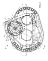
FIG. 2 is an elevation view showing a gearbox for use in propulsion of the work vehicle; -
FIG. 3 is a sectional view taken along lines 3-3 ofFIG. 2 ; -
FIG. 4 is a sectional view taken along lines 4-4 ofFIG. 2 ; -
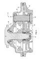
FIG. 5 is an enlarged view ofregion 5 ofFIG. 3 ; -
FIG. 6 is a sectional view taken along lines 6-6 ofFIG. 2 ; -
FIG. 7 is an elevation view showing two diametrically opposites dowels of the gearbox received in respective notches of radially projecting brake plate ears; -
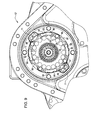
FIG. 8 is an elevation view showing a quill that has a perforated disk having a radially outer periphery notched to provide clearance for drainage holes in the housing and having circumferentially-spaced ears with radially outer notches two of which are respectively angularly aligned with the two dowels to account for manufacturing variations; -
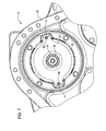
FIG. 9 is an elevation view showing the quill in a gearbox on the opposite side of the work vehicle; -
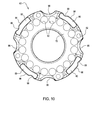
FIG. 10 is an elevation view of the quill; -
FIG. 11 is a perspective view of a piston of a brake of the gearbox; and -
FIG. 12 is an elevation view of the piston. - Referring to
FIGS. 1 and2 , awork vehicle 10 has agearbox 12. Thegearbox 12 may be used in propulsion of thework vehicle 10. In such a case, the gearbox may be, for example, a final drive for thework vehicle 10 so as to be configured to provide a rotary speed reduction, and corresponding torque increase, from apropulsion input 14 of thework vehicle 10 to apropulsion output 16 of thework vehicle 10. - In the illustrated example, the
work vehicle 12 is a track-type vehicle (e.g., a crawler dozer or crawler loader). In such a case, thevehicle 10 has twotrack assemblies 18 positioned on opposite sides of thevehicle 12, one of which is shown diagrammatically inFIG. 1 . Eachtrack assembly 18 has an endless ground-engaging track 20 trained about rotary elements of thetrack assembly 18 including a drive sprocket configured to engage thetrack 20 drivingly and positioned at the rear of thetrack assembly 18 or some other suitable location. The drive sprocket of eachtrack assembly 18 provides apropulsion output 16. - The
vehicle 10 has twohydrostatic transmissions 22, one of which is shown diagrammatically inFIG. 1 . Eachhydrostatic transmission 22 has ahydraulic pump 24 and a hydraulic motor that is coupled fluidly to thepump 24 and that provides apropulsion input 14. Thepumps 24 are driven by an internal combustion engine (not shown) of thevehicle 12 via a gearbox (not shown). In other track-type vehicle examples, one or more electric drives may be used respectively in place of the hydrostatic transmissions, with an electric motor as thepropulsion input 14 for eachgearbox 12. - In other examples, the
vehicle 10 may be a wheeled vehicle, with thegearbox 12 driven mechanically by an axle, hydraulically by a hydraulic motor, electrically by an electric motor, or the like. In such a case, the motor or axle provides a propulsion input and the associated wheel provides a propulsion output. - For the sake of providing an example, the
propulsion input 14 and thepropulsion output 16 are described below respectively as a motor and a sprocket. - Referring to
FIG. 3 , by way of example, thegearbox 12 is illustrated as a left-hand gearbox for use as a final drive on the left-hand side of thevehicle 10. It is to be understood that a corresponding right-hand gearbox may be used as a final drive on the right-hand side of thevehicle 10. - The
gearbox 12 has ahousing 26, a first orinput shaft 28, a second oroutput shaft 30, and a gear set 32 operably coupled to theshafts input shaft 28 to theoutput shaft 30. Atubular coupler 34 may be splined to thefirst shaft 28 and to the output shaft of a respective motor 14 (propulsion input) so as to couple themotor 14 and theshaft 28 together mechanically. Theoutput shaft 28 may have a flange to which sprocket segments may be bolted circumferentially therearound to provide a sprocket 16 (propulsion output). - Referring to
FIGS. 3 and4 , in the illustrated example the gear set 32 has a number of gears cooperating to provide a speed reduction and a torque increase. The gear set 32 includesgears pinion shaft 46. Thegear 36 is an input gear mounted on the input shaft 28 (e.g., integral therewith). Thegears output shaft 30 via two bearings (e.g., rolling-element bearings, such as, for example, tapered roller bearings). Thegear 42 is splined onto thepinion shaft 46. Thegear 44 is splined onto theoutput shaft 30. Thegears gear 38 is larger in diameter than thegear 36 and thegear 40. Thegears gear 42 larger in diameter than thegear 40. Thegear 44 meshes withgear teeth 48 of thepinion shaft 46, thegear 44 larger in diameter than thepinion shaft 46 at itsgear teeth 48. The power flow is thus from theinput shaft 28 sequentially through thegear 36, thegear 38, thegear 40, thegear teeth 48 of thepinion shaft 46, and thegear 44 to theoutput shaft 30. One of ordinary skill in the art will recognize that the gear set 32 can be configured in a wide variety of ways to achieve a desired speed and/or torque output. - Referring to
FIG. 4 , thepinion shaft 46 is mounted within thehousing 26 for rotation relative thereto about its rotation axis. Thepinion shaft 46 is positioned within two bearings (e.g., rolling-element bearings, such as, for example, tapered roller bearings) at opposite ends of theshaft 46. Acover 50 of thehousing 26 is fastened to afirst body 52 of the housing 26 (e.g., with four threaded bolts received in respective threaded holes of the first housing body 52) and contacts one of the bearings to load the bearing axially relative to the rotation axis of thepinion shaft 46 to limit axial endplay of thepinion shaft 46. One or more shims may be positioned between thecover 50 and thefirst housing body 52 to set the desired axial load on that bearing. - The
output shaft 30 is mounted within thehousing 26 to rotate relative thereto about its rotation axis. Theshaft 30 is positioned within two bearings (e.g., rolling-element bearings, such as, for example, tapered roller bearings) at opposite ends of theshaft 30 to rotate relative to thehousing 26 about its rotation axis. Anend plate 54 is fastened to an end of the shaft 30 (e.g., with four threaded bolts received in respective threaded holes of the shaft 30) in contact with one of the bearings to load the bearing axially relative to the rotation axis of theshaft 30 to limit axial endplay of theshaft 30. Theshaft 30 extends through a hole of asecond body 56 of thehousing 26, the first andsecond housing bodies housing bodies FIG. 4 , to allow for tighter tolerancing than a bolt, to facilitate alignment of the twohousing bodies gears output shaft 30 to rotate relative to theshaft 30 about the rotation axis of theoutput shaft 30. The cluster gear is positioned on two bearings (e.g., rolling-element bearings, such as, for example, tapered roller bearings) positioned on theshaft 30. - Referring to
FIG. 5 , theinput shaft 28 is mounted within thefirst housing body 56 of thehousing 26 in a manner so as to limit its axial endplay relative to arotation axis 57 of theinput shaft 28. Thegearbox 12 has afirst bearing 58 and a second bearing 60 (e.g., both rolling-element bearings, such as, for example, tapered roller bearings), which are positioned within thefirst housing body 52 of thehousing 26. Theinput shaft 28 is positioned within thebearings housing 26 about therotation axis 57. - An
annular quill 63 is mounted to thefirst housing body 52 of thehousing 26. Thequill 63 is positioned in contact with thesecond bearing 60 so as to load thebearing 60 axially relative to theaxis 57 to limit axial endplay of theshaft 28. Thequill 63 is fastened to thehousing 26 with a number of fasteners 61 (e.g., four threaded bolts and four washers associated respectively with the bolts). Eachfastener 61 extends through arespective hole 62 of thequill 63 into a threaded hole of thefirst housing body 52. One ormore shims 108 may be positioned axially between thequill 63 and thefirst housing body 52 relative to theaxis 57 in the event that there may be an axial clearance between thequill 63 and thefirst housing body 56 of thehousing 26 relative to theaxis 57 when thequill 63 is installed against the second bearing 60 (e.g., 6shims 108 which have the same shape and collectively stack up nominally to about one millimeter thickness; different individual shim thicknesses, such as, for example, three different thickness sizes, may be used to provide the desired spacing). - The
gearbox 12 has abrake 64 for braking rotation of theshaft 28 about therotation axis 57 and ahydraulic brake release 65 for releasing thebrake 64 to rotate about therotation axis 57. Thebrake release 65 has apiston 68 configured to move axially toward thequill 63 relative to theaxis 57 to release thebrake 64 in response to hydraulic pressure. The hydraulic pressure is due to hydraulic fluid (e.g., hydraulic oil) introduced into an annular chamber defined between thepiston 68 and athird body 70 of thehousing 26 fastened to thefirst housing body 52, the hydraulic fluid introduced into the chamber through a port of thethird housing body 70. Thequill 63 is positioned to limit axial, brake-releasing movement of thepiston 68 relative to therotation axis 57. The piston may be constructed, for example, as a casting (e.g., nodular iron). - The
third housing body 70 is fastened to thefirst housing body 52 with a number of fasteners 77 (e.g., four), eachfastener 77 including a threaded stud extending through thethird housing body 70 into a threaded hole of thefirst housing body 52, a nut threaded onto the stud, and a washer between the nut and thethird housing body 70. Each stud is elongated to provide a motor mount for themotor 14. An annular seal made, for example, of cork rubber is positioned between the first andthird housing bodies - The
brake 64 hasbrake disks 66 and brake plates 67 (which may also be referred to as "separator plates" made, for example, of steel) interleaved with thebrake disks 66 such that thebrake disks 66 and thebrake plates 67 provide abrake pack 73. Thebrake pack 73 is spring-biased to a braking configuration. Thebrake pack 73 relaxes so as to release thebrake 64 when thebrake release 65 is activated. Eachbrake disk 66 has friction material on both sides (e.g., fibrous material) and is splined to thecoupler 34 for rotation therewith relative to therotation axis 57. - Referring to
FIGS. 6 and7 , thebrake plates 67 are doweled to the first andthird housing bodies rotation axis 57. Eachbrake plate 67 has two ears circumferentially spaced about its periphery so as to be diametrically opposite to one another relative to therotation axis 57, each ear having anotch 69. Eachbrake plate 67 thus, exemplarily, has twonotches 69. Thegearbox 12 has two unthreadeddowels 71 diametrically opposite to one another relative to therotation axis 57 and received in respective holes in the first andthird housing bodies first dowel 71 extends through thefirst notch 69 of eachbrake plate 67, and thesecond dowel 71 extends through thesecond notch 69 of eachbrake plate 67. As such, eachdowel 71 is received by anotch 69 of eachbrake plate 67. Use of twodowels 71 limits lateral movement of theplates 67 and thus lateral movement of theinput shaft 28. Asingle dowel 71 may be used with ashaft 28 that is larger in order to compensate for the lateral forces. - Referring to
FIGS. 5 and6 , thequill 63 has anannular disk 72 received within a cylindrical bore of the first housing body 52 (e.g., right circular cylinder) and extending radially along awall 74 of thefirst housing body 52 of thehousing 26 relative to therotation axis 57, and aring 76 projecting from thedisk 72 in a firstaxial direction 78 radially between thesecond bearing 60 and thehousing wall 74 relative to therotation axis 57. Thedisk 72 and thering 76 cooperate to provide an annular cup 82 in which anouter race 84 of thesecond bearing 60 is nested, each of thebearings outer race 84, rolling elements positioned between the inner and outer races (e.g., tapered rollers), and a cage holding the rolling elements in spaced-apart relation to one another. Thedisk 72 comprises anouter portion 86 radially outwardly from thering 76 relative to theaxis 57 and aninner portion 88 radially inward from thering 76 relative to theaxis 57. Theinner portion 88 and thering 76 cooperate to provide the cup 82. Thequill 63 may be constructed, for example, as a casting (e.g., gray iron), in which case thequill 63 may be cast and then machined. - The
ring 76 has a chamfered pilot portion and a chamfered pilot-alignment portion. The pilot portion is adjacent to thedisk 72 and is pressed into a hole in thewall 74. The pilot-alignment portion has a diameter smaller than that of the pilot portion, facilitating alignment of the pilot portion with that hole during assembly. - Referring to
FIGS. 5 ,6 ,8 , and10 , thequill 63 has at least oneear 80 positioned to limit axial, brake-releasing movement of thepiston 68 relative to therotation axis 57. Exemplarily, thequill 63 has plural ears 80 (e.g., four) projecting from thedisk 72 in a secondaxial direction 83 opposite the firstaxial direction 78 relative to therotation axis 57 to limit brake-releasing movement of thepiston 68 in the firstaxial direction 78. Eachear 80 projects axially from theouter portion 86 relative to therotation axis 57. Use ofplural ears 80 provides for a relatively compact design of thequill 63, in that anotch 96 and a fastener-receivinghole 62 are positioned circumferentially betweenadjacent ears 80. Alternatively, thequill 63 could have a single,annular ear 80, such aquill 63 having a larger diameter to allow room for theholes 62 and thenotches 96. - Referring to
FIG. 6 , thegearbox 12 hassprings 90 urging yieldably thebrake 64 toward a braking configuration. Theouter portion 86 of thedisk 72 has spring-receivingholes 92 spaced circumferentially relative to therotation axis 57 and extending axially through thedisk 72 relative to therotation axis 57, as shown, for example, inFIGS. 8 and10 . Thesprings 90 are positioned respectively in the spring-receivingholes 92, such that the spring-receivingholes 90 receive respectively thesprings 90. Theears 80 are spaced circumferentially relative to therotation axis 57 and positioned radially outwardly from thesprings 90 relative to therotation axis 57. Theholes 92 may be through-holes, in which case thesprings 90 extend through theholes 92 into contact with asurface 93 of thehousing wall 74. There may be, for example, 20 springs 90 and 20 spring-receivingholes 92, although it is understood that any suitable number of springs and spring-receiving holes may be employed. Thequill 63 and thesprings 90 are aligned axially with thebrake 64 and thebrake release 65 relative to therotation axis 57. Thebrake pack 73 and thepiston 68 are positioned on a first side of areaction plate 94 of thebrake 64. Thepiston 68 contacts thereaction plate 94. Thequill 63 and thesprings 90 are positioned on a second side of thereaction plate 94 opposite the first side. Thesprings 90 contact thereaction plate 94 so as to urge yieldably thebrake 64 toward the braking configuration. Thebrake pack 73 contacts thereaction plate 94 when thebrake 64 is positioned in its braking configuration. Theears 80 contact thereaction plate 94 so as to limit axial, brake-releasing movement of thepiston 68 relative to therotation axis 57 when thebrake release 65 is activated (FIG. 6 ). It is to be understood that thesprings 90 will not yet have gone solid at the point that theears 80 contact the reaction plate 94 (thesprings 90 in the drawings should not be taken as having already gone solid; rather thesprings 90 are shown in the drawings for illustrative purposes so as to be indicative of springs in the respective locations). - Referring to
FIG. 8 , thequill 63 has at least onenotch 96 in its radially outer periphery relative to therotation axis 57. Thenotch 96 is angularly aligned with adrainage hole 97 in thefirst housing body 52 relative to therotation axis 57 to provide clearance for fluid to flow through thenotch 96 between thequill 63 and thehousing 26 to thedrainage hole 97. The fluid may be, for example, hydraulic fluid used to lubricate and cool the gearbox 12 (e.g., hydraulic oil). In the illustrated example, thefirst housing body 52 has two such drainage holes 97 circumferentially spaced about the radially outer periphery of thequill 63 relative to therotation axis 57, such that thequill 63 has twonotches 96 angularly aligned respectively with the twodrainage hole 97 relative to the rotation axis 57 (i.e., thequill 63 may have two notches 96). Thequill 63 exemplarily has fournotches 96 spaced circumferentially about the radially outer periphery of thequill 63 relative to therotation axis 57, so that thequill 64 is symmetrical, promoting easy of assembly. Fluid enters an interior region of aninput unit 106 of thegearbox 12 in response to meshing of theinput gear 36 and thegear 38 of the cluster gear ("splash-lubrication"). The drainage holes 97 provide a return path for the fluid to return from theinput unit 106 to the main interior region of thehousing 26. Thefirst housing body 52 may have asingle drainage hole 97. - At least one of the
ears 80 has anotch 99 angularly aligned with adowel 71 relative to therotation axis 57, allowing for manufacturing variation between thequill 63 and thedowel 71. A radiallyouter surface 98 ofsuch ear 80 relative to therotation axis 57 has thenotch 99 receiving thedowel 71. Since there may be twodowels 71, twoears 80 may be so configured. Exemplarily, eachear 80 is so configured, so that thequill 64 is symmetrical, promoting ease of assembly. - Referring to
FIG. 9 , thequill 63 is shown as part of a right-hand gearbox 12' for use as a final drive on the right-hand side of thevehicle 10. The gearbox 12' is similar to thegearbox 12. Thedowels 71 and drainage holes 97 of the gearbox 12' may be oriented somewhat differently relative to thequill 63 as compared to thegearbox 12. For example, two of thenotches 96 of thequill 63 may be angularly aligned respectively with the twodowels 71, allowing for manufacturing variation between thequill 63 and thedowels 71. One of the thosenotches 96 may also be at least partially angularly aligned with one of the drainage holes 97 relative to therotation axis 57, and anothernotch 96 may be angularly aligned with theother drainage hole 97 relative to therotation axis 57, providing clearance for fluid to flow through thenotch 96 between thequill 63 and thehousing 26 to thedrainage hole 97. - Referring to
FIGS. 11 and 12 , in the illustrated example, thepiston 68 has aring 100 andlegs 102 spaced circumferentially about therotation axis 57. The ring has a radially outer groove extending circumferentially around the radially outer periphery of the ring and receiving an O-ring seal of thebrake release 65 therein to establish a sealed connection between thepiston 68 and thethird housing body 70. Thering 100 has a radially inner groove extending circumferentially around the radially inner periphery of thering 100 and receiving an O-ring seal of thebrake release 65 therein to establish a sealed connection between thepiston 68 and thethird housing body 70. Thelegs 102 extend axially from thering 100 relative to therotation axis 57. An axial face of thering 100 has a pair ofcircumferential grooves 104. Thepiston 68 may take any suitable configuration for releasing thebrake 64 in response to hydraulic pressure. - An
input unit 106 of thegearbox 12 thus includes theinput shaft 28, thebearings quill 63, any shims between thequill 63 and thefirst housing body 52, thesprings 90, thebrake 64, thebrake release 65, thedowels 71, thethird housing body 70, respective portions of thefirst housing body 52, the seal between thehousing bodies fasteners - The
quill 63 promotes compactness of theinput unit 106 and speed and ease of assembly of theinput unit 106. Thequill 63 is arranged and configured to load thebearing 60 axially and limit axial travel of thepiston 68, promoting the compactness of theinput unit 106. - Use of the
quill 63 promotes speed and ease of assembly of theinput unit 106. During assembly, thegearbox 12 is oriented such that therotation axis 57 is vertical. The outer race of thefirst bearing 58 is pressed into thefirst housing body 52. The rolling unit and the inner race are then installed, the rolling unit including the rolling elements and the cage holding the rolling elements. Theinput shaft 28 is installed on thefirst bearing 58. The inner race and the rolling unit of thesecond bearing 60 are installed on theinput shaft 28, and the outer race of thesecond bearing 60 is pressed into the cup 82 of thequill 63. Thequill 63 and the outer race pressed therein are installed such that thequill 63 is angularly aligned with thedowels 71 already installed, or the holes that receive thedowels 71 if thedowels 71 are not yet installed, and the drainage holes 97. Before fastening of thequill 63 with thefasteners 61, any gap between thedisk 72 of thequill 63 and thesurface 93 of thehousing wall 74 is measured to determine how many, if any, shims to place between thedisk 72 and thesurface 93 in order load thebearing 60 so as to limit axial endplay of theinput shaft 28 as desired. The shims, if any, are installed between thedisk 72 and thesurface 93, and thequill 63 is fastened in place with thefasteners 61. Thebearing 60 is thus pre-loaded axially with thequill 63 in a relatively quick and easy manner, avoiding a time-consuming process involving selecting and installing a properly sized snap ring in the housing to set the bearing pre-load and endplay. - To continue with assembly of the
input unit 106, thesprings 90 are positioned respectively in the spring-receivingholes 92. Thecoupler 34 is installed on theinput shaft 28. After thedowels 71 are installed in thefirst housing body 52, thereaction plate 94 is installed on theears 80 of thequill 63 in angular alignment with thedowels 71. Thebrake pack 73 is installed on thereaction plate 94, with thebrake disks 66 splined on thecoupler 34 and thebrake plates 67 in angular alignment with thedowels 71. Thethird housing body 70, with thepiston 68 pre-assembled to thethird housing body 70, is then fastened to thefirst housing body 52 with thefasteners 77, with a seal between thehousing bodies - The
quill 63 is thus used to set the axial endplay of the first andsecond bearings input shaft 28 relative to therotation axis 57. In so doing, thequill 63 axially and radially locates theouter race 84 of the second bearing 60 (known as a "cup" in the case of a tapered roller bearing) relative to therotation axis 57 such that the desired endplay setting is achieved. Thequill 63 retains thebrake piston 68, and is exemplarily used to locate thesprings 90. Thequill 63 may thus be a multifunction component promoting compactness of theinput unit 106 and speed and ease of assembly of theinput unit 106. - For ease of representation, the threaded members referred to herein are shown in simplified, unthreaded form, it being understood that such members would be threaded. Further, for ease of representation, the O-rings shown in the drawings are depicted in their relaxed state, it being understood that they would deform upon compression in actual use.
- While the disclosure has been illustrated and described in detail in the drawings and foregoing description, such illustration and description is to be considered as exemplary and not restrictive in character, it being understood that illustrative embodiment(s) have been shown and described and that all changes and modifications that come within the spirit of the disclosure are desired to be protected. It will be noted that alternative embodiments of the present disclosure may not include all of the features described yet still benefit from at least some of the advantages of such features. Those of ordinary skill in the art may readily devise their own implementations that incorporate one or more of the features of the present disclosure and fall within the spirit and scope of the present invention as defined by the appended claims.
Claims (14)
- A gearbox, comprising:a housing (26),a bearing (58, 60) positioned within the housing (26),a shaft (28) positioned within the bearing (58, 60) to rotate relative to the housing (26) about a rotation axis (57),a gear set (32) positioned within the housing (26) and operably coupled to the shaft (28),a brake (64) for braking rotation of the shaft (28) about the rotation axis (57),a brake release (65) for releasing the brake (64) to rotate about the rotation axis (57), andan annular quill (63) mounted to the housing (26), the brake release (65) comprising a piston (68) configured to move axially toward the quill (63) relative to the rotation axis (57) to release the brake (64) in response to hydraulic pressure, the quill (63) positioned in contact with the bearing (58, 60) so as to load the bearing (58, 60) axially relative to the rotation axis (57) and positioned to limit axial, brake-releasing movement of the piston relative to the rotation axis (57).
- The gearbox of claim 1, wherein the quill (63) comprises an annular disk (72) and ears (80) spaced circumferentially relative to the rotation axis (57) and projecting axially from the disk (72) relative to the rotation axis (57) to limit axial, brake-releasing movement of the piston (68) relative to the rotation axis (57).
- The gearbox of claim 2, comprising springs (90) urging yieldably the brake (64) toward a braking configuration, wherein the ears (80) are positioned radially outwardly from the springs (90) relative to the rotation axis (57).
- The gearbox of claim 2, comprising springs (90), wherein the brake (64) comprises a brake pack (73) and a reaction plate (94), the brake pack (73) and the piston (68) are positioned on a first side of the reaction plate (94), the quill (63) and the springs (90) are positioned on a second side of the reaction plate (94) opposite the first side, the piston (68) contacts the reaction plate (94), the springs (90) contact the reaction plate (94) so as to urge yieldably the brake (64) toward a braking configuration, and the ears (80) contact the reaction plate (94) so as to limit axial, brake-releasing movement of the piston (68) relative to the rotation axis (57) when the brake release (65) is activated.
- The gearbox of claim 2, comprising a dowel (71), wherein the brake (64) comprises at least one brake plate (67) comprising a notch (69) receiving the dowel (71), and an ear of the ears (80) comprises a notch (99) receiving the dowel (71).
- The gearbox of claim 1, comprising springs (90) urging yieldably the brake (64) toward a braking configuration, wherein the quill (63) comprises spring-receiving holes (92) receiving respectively the springs (90).
- The gearbox of claim 1, wherein the quill (63) comprises at least one notch (96) in its radially outer periphery relative to the rotation axis (57) to allow fluid to flow therethrough between the quill (63) and the housing (26).
- The gearbox of claim 1, wherein the quill (63) comprises an annular disk (72) extending radially along a wall (74) of the housing (26) relative to the rotation axis (57), a ring (76) projecting from the disk (72) in a first axial direction radially between the bearing (58, 60) and the housing wall (74) relative to the rotation axis (57), and ears (80) projecting from the disk (72) in a second axial direction opposite the first axial direction relative to the rotation axis (57) to limit brake-releasing movement of the piston (68) in the first axial direction, and the disk (72) and the ring (76) cooperate to provide an annular cup (82) in which an outer race (84) of the bearing (58, 60) is nested.
- The gearbox of claim 8, wherein the disk (72) comprises an outer portion (86) radially outwardly from the ring (76) relative to the rotation axis (57) and an inner portion (88) radially inward from the ring (76) relative to the rotation axis (57), the inner portion (88) and the ring (76) cooperate to provide the cup (82), and the ears (80) project axially from the outer portion (86) relative to the rotation axis (57).
- The gearbox of claim 9, comprising springs (90), wherein the outer portion (86) comprises spring-receiving holes (92) spaced circumferentially relative to the rotation axis (57) and extending axially through the disk (72) relative to the rotation axis (57), the springs (90) are positioned respectively in the spring-receiving holes (92), and the ears (80) are spaced circumferentially relative to the rotation axis (57) and positioned radially outwardly from the springs (90) relative to the rotation axis (57).
- The gearbox of claim 10, wherein the outer portion (86) comprises notches (96) spaced circumferentially about its radially outer periphery relative to the rotation axis (57) for fluid to flow therethrough between the quill (63) and the housing (26).
- The gearbox of claim 11, comprising a dowel (71), wherein the brake (64) comprises at least one brake plate (67) comprising a notch (69) receiving the dowel (71), and a radially outer surface of an ear of the ears (80) relative to the rotation axis comprises a notch (99) receiving the dowel (71).
- The gearbox of claim 1, wherein the quill (63) comprises at least one ear positioned to limit axial, brake-releasing movement of the piston (68) relative to the rotation axis (57).
- The gearbox of claim 1, wherein the gearbox (12) is a final drive for a work vehicle, and the gearbox (12) is configured to provide a rotary speed reduction from a propulsion input of the work vehicle to a propulsion output of the work vehicle.
Applications Claiming Priority (1)
| Application Number | Priority Date | Filing Date | Title |
|---|---|---|---|
| US13/248,651 US8499659B2 (en) | 2011-09-29 | 2011-09-29 | Gearbox with multi-function quill |
Publications (2)
| Publication Number | Publication Date |
|---|---|
| EP2574719A2 true EP2574719A2 (en) | 2013-04-03 |
| EP2574719A3 EP2574719A3 (en) | 2013-10-02 |
Family
ID=46826375
Family Applications (1)
| Application Number | Title | Priority Date | Filing Date |
|---|---|---|---|
| EP12184276.9A Withdrawn EP2574719A3 (en) | 2011-09-29 | 2012-09-13 | Gearbox with multi-function quill |
Country Status (3)
| Country | Link |
|---|---|
| US (1) | US8499659B2 (en) |
| EP (1) | EP2574719A3 (en) |
| CN (1) | CN103032554B (en) |
Cited By (2)
| Publication number | Priority date | Publication date | Assignee | Title |
|---|---|---|---|---|
| CN106838132A (en) * | 2017-03-30 | 2017-06-13 | 成都工业学院 | A kind of flexible locking gear reduction unit for building hoist |
| CN114000839A (en) * | 2021-10-25 | 2022-02-01 | 西南石油大学 | High efficiency tubular column dashes spiral-lock and puts |
Families Citing this family (3)
| Publication number | Priority date | Publication date | Assignee | Title |
|---|---|---|---|---|
| CN104196985A (en) * | 2014-09-03 | 2014-12-10 | 潘树东 | Reduction gear box with detachable sealing plate |
| US11807199B2 (en) * | 2019-02-22 | 2023-11-07 | Super ATV, LLC | Portal braking system |
| DE102022123640B4 (en) * | 2022-09-15 | 2025-02-27 | Schaeffler Technologies AG & Co. KG | braking device and electrically operated axle drive train of a motor vehicle |
Family Cites Families (14)
| Publication number | Priority date | Publication date | Assignee | Title |
|---|---|---|---|---|
| US3309934A (en) * | 1964-06-10 | 1967-03-21 | Mack Trucks | Gear transmission oil pump and countershaft brake mechanism |
| US3863038A (en) * | 1973-06-26 | 1975-01-28 | Lambert & Brake Corp | Disc brake |
| US4030575A (en) * | 1975-10-22 | 1977-06-21 | Caterpillar Tractor Co. | Piston assembly with safety vent means for brakes and the like |
| US4263991A (en) * | 1977-05-27 | 1981-04-28 | Lambert Brake Company | Combined failsafe and service brake |
| IT1186592B (en) * | 1985-07-10 | 1987-12-04 | Riva Calzoni Spa | PLANETARY REDUCER FOR THE MOTORIZATION OF TRACKED VEHICLES AND EARTH-MOVING MACHINES IN GENERAL |
| JP3879942B2 (en) * | 1996-02-16 | 2007-02-14 | 株式会社小松製作所 | Parking brake device structure |
| US6260668B1 (en) * | 1999-04-29 | 2001-07-17 | Highland Machinery Corporation | Brake system for electrically powered vehicles |
| FR2796886B1 (en) * | 1999-07-27 | 2002-04-12 | Poclain Hydraulics Ind | DEVICE FOR SUPPORTING A WHEEL PROVIDED WITH BRAKING MEANS |
| DE102004057987A1 (en) * | 2004-12-01 | 2006-06-08 | Hasse & Wrede Gmbh | Torsional vibration damper for a rotatable shaft, in particular a transmission or an internal combustion engine |
| US7493992B2 (en) * | 2005-08-15 | 2009-02-24 | Pt Tech., Inc. | Gearbox brake for mining machinery |
| US7258208B1 (en) * | 2006-01-25 | 2007-08-21 | Ausco Products, Inc. | Vertical mount disc brake with disc separator |
| US8631913B2 (en) | 2007-10-15 | 2014-01-21 | Deere & Company | Brake assembly for final drive |
| CN201190751Y (en) * | 2008-03-21 | 2009-02-04 | 常林股份有限公司 | Wet-type parking brake for engineering machinery |
| WO2012008438A1 (en) * | 2010-07-14 | 2012-01-19 | 日立建機株式会社 | Power transmission device |
-
2011
- 2011-09-29 US US13/248,651 patent/US8499659B2/en active Active
-
2012
- 2012-08-17 CN CN201210295548.4A patent/CN103032554B/en active Active
- 2012-09-13 EP EP12184276.9A patent/EP2574719A3/en not_active Withdrawn
Non-Patent Citations (1)
| Title |
|---|
| None |
Cited By (3)
| Publication number | Priority date | Publication date | Assignee | Title |
|---|---|---|---|---|
| CN106838132A (en) * | 2017-03-30 | 2017-06-13 | 成都工业学院 | A kind of flexible locking gear reduction unit for building hoist |
| CN114000839A (en) * | 2021-10-25 | 2022-02-01 | 西南石油大学 | High efficiency tubular column dashes spiral-lock and puts |
| CN114000839B (en) * | 2021-10-25 | 2023-09-15 | 西南石油大学 | A high-efficiency pipe string punching device |
Also Published As
| Publication number | Publication date |
|---|---|
| US8499659B2 (en) | 2013-08-06 |
| CN103032554B (en) | 2016-08-31 |
| EP2574719A3 (en) | 2013-10-02 |
| CN103032554A (en) | 2013-04-10 |
| US20130081495A1 (en) | 2013-04-04 |
Similar Documents
| Publication | Publication Date | Title |
|---|---|---|
| EP3427989B1 (en) | Axle assembly having a bearing preload bolt | |
| AU2010298629B2 (en) | Axle shaft cover plate with bearing assembly | |
| US8499659B2 (en) | Gearbox with multi-function quill | |
| US10247107B2 (en) | Accessory gearbox for gas turbine engine | |
| EP3173649B1 (en) | Axle assembly having a wet disc brake | |
| US10077829B2 (en) | Strain wave gear system | |
| EP2594825A1 (en) | Power transmission device | |
| EP3165393B1 (en) | Axle assembly having a sun gear positioning arrangement | |
| AU2010307214B2 (en) | Thrust plate for engaging a bearing of a drive assembly | |
| US11285806B2 (en) | Driving force distribution device | |
| JP5719132B2 (en) | In-wheel motor drive device | |
| JP5913925B2 (en) | Bearing device for wheels with built-in in-wheel motor | |
| KR20100089308A (en) | A carrier assembly for travel motor reducer in heavy construction equipment | |
| US11852229B2 (en) | Strain wave gear system | |
| US11345232B2 (en) | Wheel hub arrangement for a driving wheel of a vehicle | |
| CN223190955U (en) | Speed reducer, drive axle and vehicle | |
| US20140158478A1 (en) | Separator plate | |
| KR102368567B1 (en) | Reduction Gear | |
| US10272773B2 (en) | Planetary wheel drive using thrust washer—cover arrangement | |
| US10093177B2 (en) | Compact planetary wheel drive |
Legal Events
| Date | Code | Title | Description |
|---|---|---|---|
| PUAI | Public reference made under article 153(3) epc to a published international application that has entered the european phase |
Free format text: ORIGINAL CODE: 0009012 |
|
| AK | Designated contracting states |
Kind code of ref document: A2 Designated state(s): AL AT BE BG CH CY CZ DE DK EE ES FI FR GB GR HR HU IE IS IT LI LT LU LV MC MK MT NL NO PL PT RO RS SE SI SK SM TR |
|
| AX | Request for extension of the european patent |
Extension state: BA ME |
|
| PUAL | Search report despatched |
Free format text: ORIGINAL CODE: 0009013 |
|
| AK | Designated contracting states |
Kind code of ref document: A3 Designated state(s): AL AT BE BG CH CY CZ DE DK EE ES FI FR GB GR HR HU IE IS IT LI LT LU LV MC MK MT NL NO PL PT RO RS SE SI SK SM TR |
|
| AX | Request for extension of the european patent |
Extension state: BA ME |
|
| RIC1 | Information provided on ipc code assigned before grant |
Ipc: B60T 1/06 20060101ALI20130827BHEP Ipc: E21B 19/16 20060101AFI20130827BHEP |
|
| 17P | Request for examination filed |
Effective date: 20140402 |
|
| RBV | Designated contracting states (corrected) |
Designated state(s): AL AT BE BG CH CY CZ DE DK EE ES FI FR GB GR HR HU IE IS IT LI LT LU LV MC MK MT NL NO PL PT RO RS SE SI SK SM TR |
|
| STAA | Information on the status of an ep patent application or granted ep patent |
Free format text: STATUS: THE APPLICATION IS DEEMED TO BE WITHDRAWN |
|
| 18D | Application deemed to be withdrawn |
Effective date: 20160401 |