EP2574281B1 - Radiography apparatus - Google Patents
Radiography apparatus Download PDFInfo
- Publication number
- EP2574281B1 EP2574281B1 EP12186450.8A EP12186450A EP2574281B1 EP 2574281 B1 EP2574281 B1 EP 2574281B1 EP 12186450 A EP12186450 A EP 12186450A EP 2574281 B1 EP2574281 B1 EP 2574281B1
- Authority
- EP
- European Patent Office
- Prior art keywords
- supporting frame
- radiography apparatus
- rotation axis
- stopper
- stopper arm
- Prior art date
- Legal status (The legal status is an assumption and is not a legal conclusion. Google has not performed a legal analysis and makes no representation as to the accuracy of the status listed.)
- Active
Links
Images


Classifications
-
- A—HUMAN NECESSITIES
- A61—MEDICAL OR VETERINARY SCIENCE; HYGIENE
- A61B—DIAGNOSIS; SURGERY; IDENTIFICATION
- A61B6/00—Apparatus or devices for radiation diagnosis; Apparatus or devices for radiation diagnosis combined with radiation therapy equipment
- A61B6/10—Safety means specially adapted therefor
- A61B6/102—Protection against mechanical damage, e.g. anti-collision devices
- A61B6/105—Braking or locking devices
-
- A—HUMAN NECESSITIES
- A61—MEDICAL OR VETERINARY SCIENCE; HYGIENE
- A61B—DIAGNOSIS; SURGERY; IDENTIFICATION
- A61B6/00—Apparatus or devices for radiation diagnosis; Apparatus or devices for radiation diagnosis combined with radiation therapy equipment
- A61B6/44—Constructional features of apparatus for radiation diagnosis
- A61B6/4429—Constructional features of apparatus for radiation diagnosis related to the mounting of source units and detector units
-
- A—HUMAN NECESSITIES
- A61—MEDICAL OR VETERINARY SCIENCE; HYGIENE
- A61B—DIAGNOSIS; SURGERY; IDENTIFICATION
- A61B6/00—Apparatus or devices for radiation diagnosis; Apparatus or devices for radiation diagnosis combined with radiation therapy equipment
- A61B6/44—Constructional features of apparatus for radiation diagnosis
- A61B6/4429—Constructional features of apparatus for radiation diagnosis related to the mounting of source units and detector units
- A61B6/4435—Constructional features of apparatus for radiation diagnosis related to the mounting of source units and detector units the source unit and the detector unit being coupled by a rigid structure
- A61B6/4441—Constructional features of apparatus for radiation diagnosis related to the mounting of source units and detector units the source unit and the detector unit being coupled by a rigid structure the rigid structure being a C-arm or U-arm
-
- A—HUMAN NECESSITIES
- A61—MEDICAL OR VETERINARY SCIENCE; HYGIENE
- A61B—DIAGNOSIS; SURGERY; IDENTIFICATION
- A61B6/00—Apparatus or devices for radiation diagnosis; Apparatus or devices for radiation diagnosis combined with radiation therapy equipment
- A61B6/50—Apparatus or devices for radiation diagnosis; Apparatus or devices for radiation diagnosis combined with radiation therapy equipment specially adapted for specific body parts; specially adapted for specific clinical applications
- A61B6/51—Apparatus or devices for radiation diagnosis; Apparatus or devices for radiation diagnosis combined with radiation therapy equipment specially adapted for specific body parts; specially adapted for specific clinical applications for dentistry
-
- F—MECHANICAL ENGINEERING; LIGHTING; HEATING; WEAPONS; BLASTING
- F16—ENGINEERING ELEMENTS AND UNITS; GENERAL MEASURES FOR PRODUCING AND MAINTAINING EFFECTIVE FUNCTIONING OF MACHINES OR INSTALLATIONS; THERMAL INSULATION IN GENERAL
- F16M—FRAMES, CASINGS OR BEDS OF ENGINES, MACHINES OR APPARATUS, NOT SPECIFIC TO ENGINES, MACHINES OR APPARATUS PROVIDED FOR ELSEWHERE; STANDS; SUPPORTS
- F16M11/00—Stands or trestles as supports for apparatus or articles placed thereon ; Stands for scientific apparatus such as gravitational force meters
- F16M11/02—Heads
- F16M11/04—Means for attachment of apparatus; Means allowing adjustment of the apparatus relatively to the stand
- F16M11/06—Means for attachment of apparatus; Means allowing adjustment of the apparatus relatively to the stand allowing pivoting
- F16M11/08—Means for attachment of apparatus; Means allowing adjustment of the apparatus relatively to the stand allowing pivoting around a vertical axis, e.g. panoramic heads
-
- F—MECHANICAL ENGINEERING; LIGHTING; HEATING; WEAPONS; BLASTING
- F16—ENGINEERING ELEMENTS AND UNITS; GENERAL MEASURES FOR PRODUCING AND MAINTAINING EFFECTIVE FUNCTIONING OF MACHINES OR INSTALLATIONS; THERMAL INSULATION IN GENERAL
- F16M—FRAMES, CASINGS OR BEDS OF ENGINES, MACHINES OR APPARATUS, NOT SPECIFIC TO ENGINES, MACHINES OR APPARATUS PROVIDED FOR ELSEWHERE; STANDS; SUPPORTS
- F16M11/00—Stands or trestles as supports for apparatus or articles placed thereon ; Stands for scientific apparatus such as gravitational force meters
- F16M11/02—Heads
- F16M11/18—Heads with mechanism for moving the apparatus relatively to the stand
-
- F—MECHANICAL ENGINEERING; LIGHTING; HEATING; WEAPONS; BLASTING
- F16—ENGINEERING ELEMENTS AND UNITS; GENERAL MEASURES FOR PRODUCING AND MAINTAINING EFFECTIVE FUNCTIONING OF MACHINES OR INSTALLATIONS; THERMAL INSULATION IN GENERAL
- F16M—FRAMES, CASINGS OR BEDS OF ENGINES, MACHINES OR APPARATUS, NOT SPECIFIC TO ENGINES, MACHINES OR APPARATUS PROVIDED FOR ELSEWHERE; STANDS; SUPPORTS
- F16M11/00—Stands or trestles as supports for apparatus or articles placed thereon ; Stands for scientific apparatus such as gravitational force meters
- F16M11/20—Undercarriages with or without wheels
- F16M11/2085—Undercarriages with or without wheels comprising means allowing sideward adjustment, i.e. left-right translation of the head relatively to the undercarriage
-
- F—MECHANICAL ENGINEERING; LIGHTING; HEATING; WEAPONS; BLASTING
- F16—ENGINEERING ELEMENTS AND UNITS; GENERAL MEASURES FOR PRODUCING AND MAINTAINING EFFECTIVE FUNCTIONING OF MACHINES OR INSTALLATIONS; THERMAL INSULATION IN GENERAL
- F16M—FRAMES, CASINGS OR BEDS OF ENGINES, MACHINES OR APPARATUS, NOT SPECIFIC TO ENGINES, MACHINES OR APPARATUS PROVIDED FOR ELSEWHERE; STANDS; SUPPORTS
- F16M11/00—Stands or trestles as supports for apparatus or articles placed thereon ; Stands for scientific apparatus such as gravitational force meters
- F16M11/20—Undercarriages with or without wheels
- F16M11/2092—Undercarriages with or without wheels comprising means allowing depth adjustment, i.e. forward-backward translation of the head relatively to the undercarriage
-
- A—HUMAN NECESSITIES
- A61—MEDICAL OR VETERINARY SCIENCE; HYGIENE
- A61B—DIAGNOSIS; SURGERY; IDENTIFICATION
- A61B6/00—Apparatus or devices for radiation diagnosis; Apparatus or devices for radiation diagnosis combined with radiation therapy equipment
- A61B6/56—Details of data transmission or power supply, e.g. use of slip rings
Definitions
- the present invention concerns a radiography apparatus.
- the present invention can be applied to particular advantage in the sector of radiography equipment for the acquisition of dental radiographic images, in particular cone beam computed tomography images (commonly known as CBCT), to which the following discussion will make explicit reference without loss of generality.
- CBCT cone beam computed tomography images
- a radiography apparatus comprising a vertical upright extending upwards from the ground in a first direction; a vertical slide, which is mounted to perform vertical movements along the upright in the first direction, has a substantially L-shaped form and is provided with an upper arm protruding horizontally from the upright in a second direction; a first horizontal slide which moves along the upper arm in the second direction; and a second horizontal slide coupling in a sliding manner with the first horizontal slide to perform rectilinear movements in a third direction orthogonal to said first and second direction.
- the second horizontal slide supports a radiographic unit comprising an elongated bracket, at the opposite free ends of which an X ray emitter and a receiver of the X rays generated by the emitter are fixed.
- the bracket is coupled in a revolving manner, at an intermediate point thereof, to the second slide to rotate, with respect to the second slide, about an axis of rotation parallel to the first direction.
- the known radiography apparatus of the type described above is used to acquire a series of two-dimensional radiographic images from different projection angles.
- a relatively broad field of view (FOV) of the patient's dental arches is desirable.
- the X ray cone beam is not centred with respect to the geometric centre of the area to be acquired, but is appropriately decentred so as to obtain a greater field of view.
- the acquisition involves a minimum rotation of 360° of the radiographic unit about the cited axis of rotation.
- the radiographic unit must rotate according to an angle greater than 360°, preferably between 370° and 380°, about the cited axis of rotation.
- a rotation of the radiographic unit greater than 360° entails the presence of a stopper means suitable for preventing a rotation greater than the maximum and, therefore, mechanical damage to the radiography apparatus, in particular to the wiring which would be subject to excessive twisting and, at worst, could be pulled out.
- the known radiography apparatus of the type described has some drawbacks mainly arising from the fact that the stopper means normally used in said radiography apparatus is an electronic detection system suitable for detecting the instantaneous angular position of the radiographic unit about the cited axis of rotation. Consequently, the stopper means is active only when it is electrically powered, i.e. when the radiography apparatus is switched on, whereas when the radiography apparatus is switched off, the stopper means is inactive and, therefore, unable to prevent pulling out of the wiring due to any manual movement of the radiographic unit.
- the object of the present invention is to provide a radiography apparatus which is free from the drawbacks described above and is simple and inexpensive to produce.
- the reference number 1 indicates, overall, a radiography apparatus, in this case a radiographic apparatus for the acquisition of CBCT images.
- the radiography apparatus 1 comprises a fixed vertical upright 2, which extends upwards in a direction 3, and is engaged in a sliding manner by a vertical slide 4, which presents an L-shaped form with concavity facing down, and is movable along the upright 2 in the direction 3.
- the slide 4 presents a horizontal cross member 5, which protrudes from the upright 2 in a horizontal direction 6 transverse to the direction 3, and supports a first horizontal slide 7 coupled in a sliding manner with the slide 4 to perform, with respect to the slide 4 and under the action of a drive device 8 of known type, rectilinear movements in the direction 6.
- the slide 7 supports a second horizontal slide 9 coupled in a sliding manner with the slide 7 to perform, with respect to the slide 7 and under the action of a drive device 10 of known type, rectilinear movements in a horizontal direction 11 orthogonal to the directions 3 and 6.
- the upright 2 and the slides 4, 7 and 9 define a frame 12 supporting a rotating radiographic unit 13 comprising a disc 14 coupled in a revolving manner with the slide 9 to rotate, with respect to the slide 9 and under the action of an electric motor 15 connected to the disc 14 by the interposition of a belt drive 16, around a rotation axis 17 parallel to the direction 3.
- the disc 14 supports a bracket 18 of elongated shape, which is coupled centrally and angularly fixed to the disc 14, and bears, connected to its free ends, an X ray emitter 19 and a receiver 20 of the X rays emitted by the emitter 19.
- the emitter 19 and the receiver 20 protrude downwards from the bracket 18, they face each other and are arranged on opposite sides of the axis 17.
- a mechanical stopper means 21 comprising a stopper pin 22 protruding downwards from the slide 9 in the direction 3, and a stopper arm 23 mounted on an upper face of the disc 14.
- the arm 23 has an elongated shape, extends around the axis 17, and is shaped so as to define two widened end portions 23a, 23b and a narrow central portion 23c arranged between the portions 23a and 23b.
- the arm 23 is hinged to the disc 14 at the portion 23a to oscillate, with respect to the disc 14 and under the action of the pin 22, around a fulcrum axis 24 parallel to the axis 17 and the direction 3, and is moved, and normally maintained, in a rest position by a spring (not illustrated) positioned between the disc 14 and the arm 23.
- the portions 23a, 23b protrude radially towards the inside and outside respectively of the portion 23c thus defining, together with the portion 23c, two seats 25, 26, which are obtained at the ends and on opposite sides of the portion 23c, they are offset from each other both radially and tangentially, and have respective concavities facing each other.
- the portion 23c therefore connects with the portions 23a, 23b along respective surfaces 27, 28, of which the surface 27 delimits the seat 25 and the surface 28 delimits the seat 26.
- rotation of the unit 13 in a clockwise direction ( figures 3 and 6 ) is limited by engagement of the pin 22 in the seat 25, while rotation of the unit 13 in an anticlockwise direction ( figures 3 and 5 ) is limited by engagement of the pin 22 in the seat 26.
- the unit 13 is furthermore provided with a reference blade 29, which is fixed to the upper face of the disc 14 below the arm 23, and extends around the axis 17.
- the blade 29 protrudes tangentially from the arm 23, has a flat end face 30 substantially perpendicular to a direction of forward movement of the unit 13 around the axis 17, and comprises a portion 31 protruding radially from the perimeter edge of the disc 14.
- the radiography apparatus 1 furthermore comprises a detection device defined, in this case, by a photocell 32, which is fixed to the slide 9 in a position facing the disc 14, and is arranged along a path P of forward movement of the portion 31.
- the rotation of the unit 13 about the axis 17 is commanded from an initial reference position (commonly called "machine 0 position") defined at the moment when the photocell 32 is activated or de-activated by the passage of the face 30 ( figure 3 ).
- the unit 13 When the radiography apparatus 1 is switched on, the unit 13 is generally set to an indefinite angular position around the axis 17 and must be firstly moved to its initial reference position. Consequently, if the photocell 32 is intercepted by the blade 29 or by the portion 23b, the unit 13 is rotated in an anticlockwise direction until the face 30 uncovers the photocell 32, whereas if the photocell 32 is not intercepted either by the blade 29 or by the portion 23b, the unit 13 is rotated in a clockwise direction until the face 30 covers the photocell 32.
- Figure 5 shows the anticlockwise stopper position, in which the unit 13 has moved about the axis 17 according to an angle ⁇ starting from the initial reference position and the pin 22 has stopped against the seat 26.
- the photocell 32 is uncovered since the arm 23 is set to its second operating position and the portion 31 is sized so as to extend upstream of the photocell 32.
- Figure 6 shows the clockwise stopper position, in which the unit 13 has moved around the axis 17 according to an angle ⁇ starting from the initial reference position and the pin 22 has stopped against the seat 25. In this position, the photocell 32 is covered since the arm 23 is set to its first operating position.
- the blade 29 is eliminated and the arm 23 is shaped in order to perform also the function of the blade 29.
Landscapes
- Engineering & Computer Science (AREA)
- Health & Medical Sciences (AREA)
- Life Sciences & Earth Sciences (AREA)
- Medical Informatics (AREA)
- General Engineering & Computer Science (AREA)
- Heart & Thoracic Surgery (AREA)
- Surgery (AREA)
- Nuclear Medicine, Radiotherapy & Molecular Imaging (AREA)
- Optics & Photonics (AREA)
- Pathology (AREA)
- Radiology & Medical Imaging (AREA)
- Biomedical Technology (AREA)
- Physics & Mathematics (AREA)
- Molecular Biology (AREA)
- High Energy & Nuclear Physics (AREA)
- Animal Behavior & Ethology (AREA)
- General Health & Medical Sciences (AREA)
- Public Health (AREA)
- Veterinary Medicine (AREA)
- Biophysics (AREA)
- Mechanical Engineering (AREA)
- Dentistry (AREA)
- Oral & Maxillofacial Surgery (AREA)
- Apparatus For Radiation Diagnosis (AREA)
- Analysing Materials By The Use Of Radiation (AREA)
Description
- The present invention concerns a radiography apparatus.
- The present invention can be applied to particular advantage in the sector of radiography equipment for the acquisition of dental radiographic images, in particular cone beam computed tomography images (commonly known as CBCT), to which the following discussion will make explicit reference without loss of generality.
- In the sector of dental radiography, a radiography apparatus is known of the type comprising a vertical upright extending upwards from the ground in a first direction; a vertical slide, which is mounted to perform vertical movements along the upright in the first direction, has a substantially L-shaped form and is provided with an upper arm protruding horizontally from the upright in a second direction; a first horizontal slide which moves along the upper arm in the second direction; and a second horizontal slide coupling in a sliding manner with the first horizontal slide to perform rectilinear movements in a third direction orthogonal to said first and second direction.
- The second horizontal slide supports a radiographic unit comprising an elongated bracket, at the opposite free ends of which an X ray emitter and a receiver of the X rays generated by the emitter are fixed.
- The bracket is coupled in a revolving manner, at an intermediate point thereof, to the second slide to rotate, with respect to the second slide, about an axis of rotation parallel to the first direction.
- The known radiography apparatus of the type described above is used to acquire a series of two-dimensional radiographic images from different projection angles.
- In order to correctly process the radiographic images in a post-acquisition phase and reconstruct a three-dimensional volume, a relatively broad field of view (FOV) of the patient's dental arches is desirable.
- To avoid using relatively large and therefore excessively costly X ray receivers, the X ray cone beam is not centred with respect to the geometric centre of the area to be acquired, but is appropriately decentred so as to obtain a greater field of view.
- Consequently, the acquisition involves a minimum rotation of 360° of the radiographic unit about the cited axis of rotation. In reality, to take account of the initial acceleration and final deceleration, the radiographic unit must rotate according to an angle greater than 360°, preferably between 370° and 380°, about the cited axis of rotation.
- A rotation of the radiographic unit greater than 360° entails the presence of a stopper means suitable for preventing a rotation greater than the maximum and, therefore, mechanical damage to the radiography apparatus, in particular to the wiring which would be subject to excessive twisting and, at worst, could be pulled out.
- The known radiography apparatus of the type described has some drawbacks mainly arising from the fact that the stopper means normally used in said radiography apparatus is an electronic detection system suitable for detecting the instantaneous angular position of the radiographic unit about the cited axis of rotation. Consequently, the stopper means is active only when it is electrically powered, i.e. when the radiography apparatus is switched on, whereas when the radiography apparatus is switched off, the stopper means is inactive and, therefore, unable to prevent pulling out of the wiring due to any manual movement of the radiographic unit.
- The object of the present invention is to provide a radiography apparatus which is free from the drawbacks described above and is simple and inexpensive to produce.
- According to the present invention there is provided a radiography apparatus as claimed in the attached claims.
- Document
US6088424 discloses an apparatus according to the preamble ofclaim 1. - The present invention will now be described with reference to the accompanying drawings, which illustrate a non-limiting implementation example, in which:
-
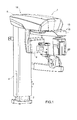
figure 1 is a schematic perspective view of a preferred embodiment of the radiography apparatus of the present invention; -
figure 2 is a schematic perspective view of a detail of the radiographic apparatus offigure 1 ; -
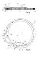
figure 3 is a schematic plan view, with parts removed for the sake of clarity, of a detail offigure 2 ; -
figure 4 is a schematic lateral view, with parts removed for the sake of clarity, of the detail offigure 3 ; -
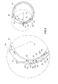
figures 5 and6 are two schematic plan views, with parts enlarged and parts removed for the sake of clarity, of the detail offigures 3 and 4 illustrated in two different operating positions; and -
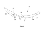
figure 7 is a schematic plan view of a detail offigures 3 to 6 . - With reference to
figures 1 and2 , thereference number 1 indicates, overall, a radiography apparatus, in this case a radiographic apparatus for the acquisition of CBCT images. - The
radiography apparatus 1 comprises a fixed vertical upright 2, which extends upwards in adirection 3, and is engaged in a sliding manner by avertical slide 4, which presents an L-shaped form with concavity facing down, and is movable along the upright 2 in thedirection 3. - The
slide 4 presents ahorizontal cross member 5, which protrudes from the upright 2 in ahorizontal direction 6 transverse to thedirection 3, and supports a firsthorizontal slide 7 coupled in a sliding manner with theslide 4 to perform, with respect to theslide 4 and under the action of adrive device 8 of known type, rectilinear movements in thedirection 6. - The
slide 7 supports a secondhorizontal slide 9 coupled in a sliding manner with theslide 7 to perform, with respect to theslide 7 and under the action of adrive device 10 of known type, rectilinear movements in a horizontal direction 11 orthogonal to thedirections - The upright 2 and the
slides frame 12 supporting a rotatingradiographic unit 13 comprising adisc 14 coupled in a revolving manner with theslide 9 to rotate, with respect to theslide 9 and under the action of anelectric motor 15 connected to thedisc 14 by the interposition of abelt drive 16, around arotation axis 17 parallel to thedirection 3. - The
disc 14 supports abracket 18 of elongated shape, which is coupled centrally and angularly fixed to thedisc 14, and bears, connected to its free ends, anX ray emitter 19 and areceiver 20 of the X rays emitted by theemitter 19. - The
emitter 19 and thereceiver 20 protrude downwards from thebracket 18, they face each other and are arranged on opposite sides of theaxis 17. - According to
figures 3, 4 and7 , the movement of theunit 13 about theaxis 17 is limited by a mechanical stopper means 21 comprising astopper pin 22 protruding downwards from theslide 9 in thedirection 3, and astopper arm 23 mounted on an upper face of thedisc 14. - The
arm 23 has an elongated shape, extends around theaxis 17, and is shaped so as to define two widenedend portions central portion 23c arranged between theportions - The
arm 23 is hinged to thedisc 14 at theportion 23a to oscillate, with respect to thedisc 14 and under the action of thepin 22, around afulcrum axis 24 parallel to theaxis 17 and thedirection 3, and is moved, and normally maintained, in a rest position by a spring (not illustrated) positioned between thedisc 14 and thearm 23. - The
portions portion 23c thus defining, together with theportion 23c, twoseats portion 23c, they are offset from each other both radially and tangentially, and have respective concavities facing each other. - The
portion 23c therefore connects with theportions respective surfaces surface 27 delimits theseat 25 and thesurface 28 delimits theseat 26. In use, rotation of theunit 13 in a clockwise direction (figures 3 and6 ) is limited by engagement of thepin 22 in theseat 25, while rotation of theunit 13 in an anticlockwise direction (figures 3 and5 ) is limited by engagement of thepin 22 in theseat 26. - With regard to the above it should be noted that:
- the stopper means 21 limits the rotation of the
unit 13 about theaxis 17 both when theradiography apparatus 1 is switched on and when theradiography apparatus 1 is switched off; and - the position and orientation of the
seats arm 23 around theaxis 24 allow theunit 13 to rotate about theaxis 17 according to an angle greater than 360°, in this case according to an angle substantially equal to 380°. - The
unit 13 is furthermore provided with areference blade 29, which is fixed to the upper face of thedisc 14 below thearm 23, and extends around theaxis 17. - The
blade 29 protrudes tangentially from thearm 23, has aflat end face 30 substantially perpendicular to a direction of forward movement of theunit 13 around theaxis 17, and comprises aportion 31 protruding radially from the perimeter edge of thedisc 14. - The
radiography apparatus 1 furthermore comprises a detection device defined, in this case, by aphotocell 32, which is fixed to theslide 9 in a position facing thedisc 14, and is arranged along a path P of forward movement of theportion 31. - In this regard it should be noted that:
- rotation of the
unit 13 in a clockwise direction allows thepin 22 to engage thesurface 28 and to move thearm 23 to a first operating position, in which theportion 23b protrudes radially towards the outside of thedisc 14 thus defining an extension of theblade 29 and crossing thephotocell 32; and - the rotation of the
unit 13 in an anticlockwise direction allows thepin 22 to engage thesurface 27 and to move thearm 23 to a second operating position, in which thearm 23 does not protrude radially towards the outside of thedisc 14 and does not cross thephotocell 32. - The rotation of the
unit 13 about theaxis 17 is commanded from an initial reference position (commonly called "machine 0 position") defined at the moment when thephotocell 32 is activated or de-activated by the passage of the face 30 (figure 3 ). - When the
radiography apparatus 1 is switched on, theunit 13 is generally set to an indefinite angular position around theaxis 17 and must be firstly moved to its initial reference position. Consequently, if thephotocell 32 is intercepted by theblade 29 or by theportion 23b, theunit 13 is rotated in an anticlockwise direction until theface 30 uncovers thephotocell 32, whereas if thephotocell 32 is not intercepted either by theblade 29 or by theportion 23b, theunit 13 is rotated in a clockwise direction until theface 30 covers thephotocell 32. -
Figure 5 shows the anticlockwise stopper position, in which theunit 13 has moved about theaxis 17 according to an angle α starting from the initial reference position and thepin 22 has stopped against theseat 26. In this position, thephotocell 32 is uncovered since thearm 23 is set to its second operating position and theportion 31 is sized so as to extend upstream of thephotocell 32. -
Figure 6 shows the clockwise stopper position, in which theunit 13 has moved around theaxis 17 according to an angle β starting from the initial reference position and thepin 22 has stopped against theseat 25. In this position, thephotocell 32 is covered since thearm 23 is set to its first operating position. - In other words:
- the
unit 13 can move around theaxis 17 according to an overall angle α+β greater than 360°, in this case according to an overall angle substantially equal to 380°; - the combination of the
arm 23, theblade 29 and thephotocell 32 allows recognition of the angular position of theunit 13 when theradiography apparatus 1 is switched on and re-setting of theunit 13 always to the same identical initial reference position; and - the
arm 23, together with thepin 22, acts as a stopper means and, together with theblade 29 and thephotocell 32, as a device for recognition of the initial angular position of theunit 13 around theaxis 17. - According to a variation not illustrated, the
blade 29 is eliminated and thearm 23 is shaped in order to perform also the function of theblade 29.
Claims (15)
- Radiography apparatus comprising a first supporting frame (12); a radiographic unit (13) mounted on the first supporting frame (12) and comprising, in turn, a second supporting frame (14, 18) mounted to rotate, with respect to the first supporting frame (12), about a rotation axis (17), an X ray emitter (19) mounted on the second supporting frame (14, 18), and an X ray receiver (20) mounted on the second supporting frame (14, 18) to receive the X rays generated by the emitter (19); and a stopper means (21) to stop rotation of the radiographic unit (13) about said rotation axis (17);
wherein
the stopper means (21) comprises a stopper pin (22) mounted on one of said first and second supporting frames (12, 14, 18) and characterised by one single stopper arm (23) mounted on the other of said first and second supporting frames (12, 14, 18); the stopper arm (23) having two seats (25, 26) suitable for being selectively engaged by the stopper pin (22) following rotation of the second supporting frame (14, 18) in two opposite directions of forward movement. - Radiography apparatus as claimed in claim 1, wherein the two seats (25, 26) are radially and tangentially offset from each other with respect to the rotation axis (17) and have respective concavities facing each other so as to allow the second supporting frame(14, 18) to move around the rotation axis (17) according to an angle greater than 360°.
- Radiography apparatus as claimed in claim 1 or 2, wherein the two seats (25, 26) are radially offset from each other with respect to said rotation axis (17); the stopper arm (23) being movable, with respect to the second supporting frame (14, 18), between a first operating position, in which the stopper pin (22) engages a first said seat (25) following rotation of the second supporting frame (14, 18) in a first said direction of forward movement, and a second operating position wherein the stopper pin (22) engages a second said seat (26) following rotation of the second supporting frame (14, 18) in a second said direction of forward movement.
- Radiography apparatus as claimed in claim 3, wherein the stopper arm (23) is hinged to the second supporting frame (14, 18) to rotate about a fulcrum axis (24) substantially parallel to said rotation axis (17) between said first and second operating position under the thrust of said stopper pin (22).
- Radiography apparatus as claimed in claim 3 or 4 and furthermore comprising at least one spring positioned between the second supporting frame (14, 18) and the stopper arm (23) to move, and normally maintain, the stopper arm (23) in an intermediate rest position between said first and second operating position.
- Radiography apparatus as claimed in any one of the preceding claims, wherein the stopper arm (23) is shaped so as to extend around said rotation axis (17).
- Radiography apparatus as claimed in any one of the preceding claims and furthermore comprising a reference member (23, 29) mounted on the second supporting frame (14, 18) to move along a path of forward movement (P) extending around the rotation axis (17), and a detection device (32) positioned along the path of forward movement (P) to detect the presence of the reference member (23, 29).
- Radiography apparatus as claimed in claim 7, wherein the reference member (23, 29) extends around the rotation axis (17) according to a given angle, and has at least one reference element (30); the detection device (32) being configured to command stopping of the radiographic unit (13) around the rotation axis (17) in an angular position corresponding to the passage of the reference element (30) through the detection device (32).
- Radiography apparatus as claimed in claim 8, wherein the reference member (23, 29) is limited tangentially by a substantially flat free face defining said reference element (30).
- Radiography apparatus as claimed in any one of the claims from 7 to 9, wherein the stopper arm (23) defines said reference member (23, 29).
- Radiography apparatus as claimed in any one of the claims from 7 to 9, wherein the reference member (23, 29) comprises a first portion defined by a blade (29), which extends around the rotation axis (17), is fixed to the second supporting frame (14, 18) and protrudes radially towards the outside of the second supporting frame (14, 18) to cross the detection device (32).
- Radiography apparatus as claimed in claim 11, wherein the reference member (23, 29) comprises a second portion defined by the stopper arm (23).
- Radiography apparatus as claimed in claim 12 when dependent on any one of the claims from 3 to 5, wherein the stopper arm (23) is shaped so as to define an extension of the blade (29) and cross the detection device (32) when arranged in said first operating position.
- Radiography apparatus as claimed in claim 13, wherein the stopper arm (23) is shaped so as not to cross the detection device (32) when arranged in said second operating position.
- Radiography apparatus as claimed in claim 14, wherein the blade (29) extends around the rotation axis (17) according to an angle such as to extend to the outside of the detection device (32) when the stopper arm (23) is arranged in said second operating position.
Applications Claiming Priority (1)
| Application Number | Priority Date | Filing Date | Title |
|---|---|---|---|
| IT000550A ITBO20110550A1 (en) | 2011-09-27 | 2011-09-27 | DEVICE FOR THE ACQUISITION OF VOLUMETRIC CBCT RADIOGRAPHIES |
Publications (2)
| Publication Number | Publication Date |
|---|---|
| EP2574281A1 EP2574281A1 (en) | 2013-04-03 |
| EP2574281B1 true EP2574281B1 (en) | 2014-12-24 |
Family
ID=44872466
Family Applications (1)
| Application Number | Title | Priority Date | Filing Date |
|---|---|---|---|
| EP12186450.8A Active EP2574281B1 (en) | 2011-09-27 | 2012-09-27 | Radiography apparatus |
Country Status (2)
| Country | Link |
|---|---|
| EP (1) | EP2574281B1 (en) |
| IT (1) | ITBO20110550A1 (en) |
Families Citing this family (2)
| Publication number | Priority date | Publication date | Assignee | Title |
|---|---|---|---|---|
| ES2655106T3 (en) * | 2014-01-06 | 2018-02-16 | Philips Lighting Holding B.V. | Stop mechanism for a rotating device |
| KR101796350B1 (en) | 2014-04-17 | 2017-11-09 | 쎄플라 쏘씨에타 쿠퍼라티바 | Craniostat for acquiring extraoral dental radiographies |
Family Cites Families (6)
| Publication number | Priority date | Publication date | Assignee | Title |
|---|---|---|---|---|
| US3891856A (en) * | 1973-11-21 | 1975-06-24 | Picker Corp | Mount for ceiling supported X-ray tube |
| SE443913B (en) * | 1985-05-31 | 1986-03-17 | Ao Medical Products Ab | DEVICE FOR BALANCE-BALANCED X-ray stand |
| US5784435A (en) * | 1997-04-23 | 1998-07-21 | General Electric Company | X-ray tube support column on a mobile x-ray product with improved rotational flexibility |
| US6088424A (en) * | 1998-09-22 | 2000-07-11 | Vf Works, Inc. | Apparatus and method for producing a picture-in-a-picture motion x-ray image |
| JP3869360B2 (en) * | 2002-12-27 | 2007-01-17 | 三鷹光器株式会社 | Rotational support structure for surgical microscope |
| JP5467690B2 (en) * | 2009-04-07 | 2014-04-09 | 朝日レントゲン工業株式会社 | X-ray CT imaging system |
-
2011
- 2011-09-27 IT IT000550A patent/ITBO20110550A1/en unknown
-
2012
- 2012-09-27 EP EP12186450.8A patent/EP2574281B1/en active Active
Also Published As
| Publication number | Publication date |
|---|---|
| ITBO20110550A1 (en) | 2013-03-28 |
| EP2574281A1 (en) | 2013-04-03 |
Similar Documents
| Publication | Publication Date | Title |
|---|---|---|
| AU2015343319B2 (en) | Pivoting paddle apparatus for mammography/tomosynthesis x-ray system | |
| CN101947360B (en) | Medical device having a collision-protection apparatus | |
| US10098596B2 (en) | Methods and apparatus for imaging with detectors having moving detector heads | |
| EP4081292B1 (en) | Control systems | |
| US20030194051A1 (en) | Tomosynthesis X-ray mammogram system and method with automatic drive system | |
| US10881374B2 (en) | Mammography imaging arrangement for tomosynthesis | |
| US7581883B2 (en) | Radiographic apparatus | |
| WO2008092009A2 (en) | Adjustable scanner | |
| EP2596752A1 (en) | Medical imaging apparatus | |
| CN105813569A (en) | Systems and methods for multi-modality imaging | |
| EP2574281A1 (en) | Radiography apparatus | |
| JP2017080042A (en) | X-ray diagnostic imaging equipment | |
| JP2012232118A (en) | System and method for orienting x-ray detector | |
| EP2826424B1 (en) | X-ray photographing apparatus | |
| US10219762B2 (en) | X-ray CT device and imaging method for X-ray CT images | |
| US12023183B2 (en) | Radiography system, image processing device, image processing method, and image processing program | |
| US9532753B2 (en) | X-ray imaging device | |
| US10937560B2 (en) | Beam-limiting device for radiographic apparatuses | |
| US9427204B2 (en) | Method and C-arm system for acquisition of a two-dimensional, X-ray projection image | |
| US20150320380A1 (en) | Medical image diagnostic apparatus, medical image processing apparatus, medical image processing method and gantry moving position determination method | |
| CN203458399U (en) | Column and digital radiography system | |
| KR20150062521A (en) | Apparatus for Obtaining Computed Tomography | |
| US20080164419A1 (en) | Methods and Apparatus for Keystone Effect | |
| CN104854662A (en) | X-ray apparatus | |
| US20200245964A1 (en) | Radiographic Imaging Apparatus |
Legal Events
| Date | Code | Title | Description |
|---|---|---|---|
| PUAI | Public reference made under article 153(3) epc to a published international application that has entered the european phase |
Free format text: ORIGINAL CODE: 0009012 |
|
| AK | Designated contracting states |
Kind code of ref document: A1 Designated state(s): AL AT BE BG CH CY CZ DE DK EE ES FI FR GB GR HR HU IE IS IT LI LT LU LV MC MK MT NL NO PL PT RO RS SE SI SK SM TR |
|
| AX | Request for extension of the european patent |
Extension state: BA ME |
|
| 17P | Request for examination filed |
Effective date: 20131002 |
|
| RBV | Designated contracting states (corrected) |
Designated state(s): AL AT BE BG CH CY CZ DE DK EE ES FI FR GB GR HR HU IE IS IT LI LT LU LV MC MK MT NL NO PL PT RO RS SE SI SK SM TR |
|
| RIC1 | Information provided on ipc code assigned before grant |
Ipc: A61B 6/10 20060101AFI20140520BHEP Ipc: A61B 6/14 20060101ALI20140520BHEP Ipc: F16M 11/08 20060101ALI20140520BHEP Ipc: A61B 6/00 20060101ALN20140520BHEP |
|
| GRAP | Despatch of communication of intention to grant a patent |
Free format text: ORIGINAL CODE: EPIDOSNIGR1 |
|
| INTG | Intention to grant announced |
Effective date: 20140716 |
|
| GRAS | Grant fee paid |
Free format text: ORIGINAL CODE: EPIDOSNIGR3 |
|
| GRAA | (expected) grant |
Free format text: ORIGINAL CODE: 0009210 |
|
| AK | Designated contracting states |
Kind code of ref document: B1 Designated state(s): AL AT BE BG CH CY CZ DE DK EE ES FI FR GB GR HR HU IE IS IT LI LT LU LV MC MK MT NL NO PL PT RO RS SE SI SK SM TR |
|
| REG | Reference to a national code |
Ref country code: GB Ref legal event code: FG4D |
|
| REG | Reference to a national code |
Ref country code: CH Ref legal event code: EP |
|
| REG | Reference to a national code |
Ref country code: IE Ref legal event code: FG4D |
|
| REG | Reference to a national code |
Ref country code: AT Ref legal event code: REF Ref document number: 702712 Country of ref document: AT Kind code of ref document: T Effective date: 20150115 |
|
| REG | Reference to a national code |
Ref country code: DE Ref legal event code: R096 Ref document number: 602012004480 Country of ref document: DE Effective date: 20150219 |
|
| REG | Reference to a national code |
Ref country code: NL Ref legal event code: VDEP Effective date: 20141224 |
|
| PG25 | Lapsed in a contracting state [announced via postgrant information from national office to epo] |
Ref country code: LT Free format text: LAPSE BECAUSE OF FAILURE TO SUBMIT A TRANSLATION OF THE DESCRIPTION OR TO PAY THE FEE WITHIN THE PRESCRIBED TIME-LIMIT Effective date: 20141224 Ref country code: NO Free format text: LAPSE BECAUSE OF FAILURE TO SUBMIT A TRANSLATION OF THE DESCRIPTION OR TO PAY THE FEE WITHIN THE PRESCRIBED TIME-LIMIT Effective date: 20150324 |
|
| REG | Reference to a national code |
Ref country code: LT Ref legal event code: MG4D |
|
| PG25 | Lapsed in a contracting state [announced via postgrant information from national office to epo] |
Ref country code: GR Free format text: LAPSE BECAUSE OF FAILURE TO SUBMIT A TRANSLATION OF THE DESCRIPTION OR TO PAY THE FEE WITHIN THE PRESCRIBED TIME-LIMIT Effective date: 20150325 Ref country code: RS Free format text: LAPSE BECAUSE OF FAILURE TO SUBMIT A TRANSLATION OF THE DESCRIPTION OR TO PAY THE FEE WITHIN THE PRESCRIBED TIME-LIMIT Effective date: 20141224 Ref country code: HR Free format text: LAPSE BECAUSE OF FAILURE TO SUBMIT A TRANSLATION OF THE DESCRIPTION OR TO PAY THE FEE WITHIN THE PRESCRIBED TIME-LIMIT Effective date: 20141224 Ref country code: SE Free format text: LAPSE BECAUSE OF FAILURE TO SUBMIT A TRANSLATION OF THE DESCRIPTION OR TO PAY THE FEE WITHIN THE PRESCRIBED TIME-LIMIT Effective date: 20141224 Ref country code: LV Free format text: LAPSE BECAUSE OF FAILURE TO SUBMIT A TRANSLATION OF THE DESCRIPTION OR TO PAY THE FEE WITHIN THE PRESCRIBED TIME-LIMIT Effective date: 20141224 |
|
| REG | Reference to a national code |
Ref country code: AT Ref legal event code: MK05 Ref document number: 702712 Country of ref document: AT Kind code of ref document: T Effective date: 20141224 |
|
| PG25 | Lapsed in a contracting state [announced via postgrant information from national office to epo] |
Ref country code: NL Free format text: LAPSE BECAUSE OF FAILURE TO SUBMIT A TRANSLATION OF THE DESCRIPTION OR TO PAY THE FEE WITHIN THE PRESCRIBED TIME-LIMIT Effective date: 20141224 |
|
| PG25 | Lapsed in a contracting state [announced via postgrant information from national office to epo] |
Ref country code: SK Free format text: LAPSE BECAUSE OF FAILURE TO SUBMIT A TRANSLATION OF THE DESCRIPTION OR TO PAY THE FEE WITHIN THE PRESCRIBED TIME-LIMIT Effective date: 20141224 Ref country code: RO Free format text: LAPSE BECAUSE OF FAILURE TO SUBMIT A TRANSLATION OF THE DESCRIPTION OR TO PAY THE FEE WITHIN THE PRESCRIBED TIME-LIMIT Effective date: 20141224 Ref country code: CZ Free format text: LAPSE BECAUSE OF FAILURE TO SUBMIT A TRANSLATION OF THE DESCRIPTION OR TO PAY THE FEE WITHIN THE PRESCRIBED TIME-LIMIT Effective date: 20141224 Ref country code: ES Free format text: LAPSE BECAUSE OF FAILURE TO SUBMIT A TRANSLATION OF THE DESCRIPTION OR TO PAY THE FEE WITHIN THE PRESCRIBED TIME-LIMIT Effective date: 20141224 Ref country code: EE Free format text: LAPSE BECAUSE OF FAILURE TO SUBMIT A TRANSLATION OF THE DESCRIPTION OR TO PAY THE FEE WITHIN THE PRESCRIBED TIME-LIMIT Effective date: 20141224 |
|
| PG25 | Lapsed in a contracting state [announced via postgrant information from national office to epo] |
Ref country code: PL Free format text: LAPSE BECAUSE OF FAILURE TO SUBMIT A TRANSLATION OF THE DESCRIPTION OR TO PAY THE FEE WITHIN THE PRESCRIBED TIME-LIMIT Effective date: 20141224 Ref country code: IS Free format text: LAPSE BECAUSE OF FAILURE TO SUBMIT A TRANSLATION OF THE DESCRIPTION OR TO PAY THE FEE WITHIN THE PRESCRIBED TIME-LIMIT Effective date: 20150424 Ref country code: AT Free format text: LAPSE BECAUSE OF FAILURE TO SUBMIT A TRANSLATION OF THE DESCRIPTION OR TO PAY THE FEE WITHIN THE PRESCRIBED TIME-LIMIT Effective date: 20141224 |
|
| REG | Reference to a national code |
Ref country code: DE Ref legal event code: R097 Ref document number: 602012004480 Country of ref document: DE |
|
| PG25 | Lapsed in a contracting state [announced via postgrant information from national office to epo] |
Ref country code: DK Free format text: LAPSE BECAUSE OF FAILURE TO SUBMIT A TRANSLATION OF THE DESCRIPTION OR TO PAY THE FEE WITHIN THE PRESCRIBED TIME-LIMIT Effective date: 20141224 |
|
| PLBE | No opposition filed within time limit |
Free format text: ORIGINAL CODE: 0009261 |
|
| STAA | Information on the status of an ep patent application or granted ep patent |
Free format text: STATUS: NO OPPOSITION FILED WITHIN TIME LIMIT |
|
| 26N | No opposition filed |
Effective date: 20150925 |
|
| PG25 | Lapsed in a contracting state [announced via postgrant information from national office to epo] |
Ref country code: SI Free format text: LAPSE BECAUSE OF FAILURE TO SUBMIT A TRANSLATION OF THE DESCRIPTION OR TO PAY THE FEE WITHIN THE PRESCRIBED TIME-LIMIT Effective date: 20141224 |
|
| PG25 | Lapsed in a contracting state [announced via postgrant information from national office to epo] |
Ref country code: MC Free format text: LAPSE BECAUSE OF FAILURE TO SUBMIT A TRANSLATION OF THE DESCRIPTION OR TO PAY THE FEE WITHIN THE PRESCRIBED TIME-LIMIT Effective date: 20141224 Ref country code: LU Free format text: LAPSE BECAUSE OF FAILURE TO SUBMIT A TRANSLATION OF THE DESCRIPTION OR TO PAY THE FEE WITHIN THE PRESCRIBED TIME-LIMIT Effective date: 20150927 |
|
| REG | Reference to a national code |
Ref country code: CH Ref legal event code: PL |
|
| PG25 | Lapsed in a contracting state [announced via postgrant information from national office to epo] |
Ref country code: BE Free format text: LAPSE BECAUSE OF FAILURE TO SUBMIT A TRANSLATION OF THE DESCRIPTION OR TO PAY THE FEE WITHIN THE PRESCRIBED TIME-LIMIT Effective date: 20141224 |
|
| REG | Reference to a national code |
Ref country code: IE Ref legal event code: MM4A |
|
| PG25 | Lapsed in a contracting state [announced via postgrant information from national office to epo] |
Ref country code: LI Free format text: LAPSE BECAUSE OF NON-PAYMENT OF DUE FEES Effective date: 20150930 Ref country code: CH Free format text: LAPSE BECAUSE OF NON-PAYMENT OF DUE FEES Effective date: 20150930 Ref country code: IE Free format text: LAPSE BECAUSE OF NON-PAYMENT OF DUE FEES Effective date: 20150927 |
|
| REG | Reference to a national code |
Ref country code: FR Ref legal event code: PLFP Year of fee payment: 5 |
|
| PG25 | Lapsed in a contracting state [announced via postgrant information from national office to epo] |
Ref country code: MT Free format text: LAPSE BECAUSE OF FAILURE TO SUBMIT A TRANSLATION OF THE DESCRIPTION OR TO PAY THE FEE WITHIN THE PRESCRIBED TIME-LIMIT Effective date: 20141224 |
|
| GBPC | Gb: european patent ceased through non-payment of renewal fee |
Effective date: 20160927 |
|
| PG25 | Lapsed in a contracting state [announced via postgrant information from national office to epo] |
Ref country code: BG Free format text: LAPSE BECAUSE OF FAILURE TO SUBMIT A TRANSLATION OF THE DESCRIPTION OR TO PAY THE FEE WITHIN THE PRESCRIBED TIME-LIMIT Effective date: 20141224 Ref country code: HU Free format text: LAPSE BECAUSE OF FAILURE TO SUBMIT A TRANSLATION OF THE DESCRIPTION OR TO PAY THE FEE WITHIN THE PRESCRIBED TIME-LIMIT; INVALID AB INITIO Effective date: 20120927 Ref country code: SM Free format text: LAPSE BECAUSE OF FAILURE TO SUBMIT A TRANSLATION OF THE DESCRIPTION OR TO PAY THE FEE WITHIN THE PRESCRIBED TIME-LIMIT Effective date: 20141224 |
|
| PG25 | Lapsed in a contracting state [announced via postgrant information from national office to epo] |
Ref country code: CY Free format text: LAPSE BECAUSE OF FAILURE TO SUBMIT A TRANSLATION OF THE DESCRIPTION OR TO PAY THE FEE WITHIN THE PRESCRIBED TIME-LIMIT Effective date: 20141224 |
|
| PG25 | Lapsed in a contracting state [announced via postgrant information from national office to epo] |
Ref country code: GB Free format text: LAPSE BECAUSE OF NON-PAYMENT OF DUE FEES Effective date: 20160927 |
|
| REG | Reference to a national code |
Ref country code: FR Ref legal event code: PLFP Year of fee payment: 6 |
|
| PG25 | Lapsed in a contracting state [announced via postgrant information from national office to epo] |
Ref country code: TR Free format text: LAPSE BECAUSE OF FAILURE TO SUBMIT A TRANSLATION OF THE DESCRIPTION OR TO PAY THE FEE WITHIN THE PRESCRIBED TIME-LIMIT Effective date: 20141224 |
|
| PG25 | Lapsed in a contracting state [announced via postgrant information from national office to epo] |
Ref country code: MK Free format text: LAPSE BECAUSE OF FAILURE TO SUBMIT A TRANSLATION OF THE DESCRIPTION OR TO PAY THE FEE WITHIN THE PRESCRIBED TIME-LIMIT Effective date: 20141224 |
|
| PG25 | Lapsed in a contracting state [announced via postgrant information from national office to epo] |
Ref country code: PT Free format text: LAPSE BECAUSE OF FAILURE TO SUBMIT A TRANSLATION OF THE DESCRIPTION OR TO PAY THE FEE WITHIN THE PRESCRIBED TIME-LIMIT Effective date: 20141224 |
|
| REG | Reference to a national code |
Ref country code: FR Ref legal event code: PLFP Year of fee payment: 7 |
|
| PG25 | Lapsed in a contracting state [announced via postgrant information from national office to epo] |
Ref country code: AL Free format text: LAPSE BECAUSE OF FAILURE TO SUBMIT A TRANSLATION OF THE DESCRIPTION OR TO PAY THE FEE WITHIN THE PRESCRIBED TIME-LIMIT Effective date: 20141224 |
|
| PGFP | Annual fee paid to national office [announced via postgrant information from national office to epo] |
Ref country code: FI Payment date: 20250820 Year of fee payment: 14 |
|
| PGFP | Annual fee paid to national office [announced via postgrant information from national office to epo] |
Ref country code: DE Payment date: 20250820 Year of fee payment: 14 |
|
| PGFP | Annual fee paid to national office [announced via postgrant information from national office to epo] |
Ref country code: IT Payment date: 20250820 Year of fee payment: 14 |
|
| PGFP | Annual fee paid to national office [announced via postgrant information from national office to epo] |
Ref country code: FR Payment date: 20250821 Year of fee payment: 14 |