EP2574081A2 - Speaker - Google Patents
Speaker Download PDFInfo
- Publication number
- EP2574081A2 EP2574081A2 EP12184153A EP12184153A EP2574081A2 EP 2574081 A2 EP2574081 A2 EP 2574081A2 EP 12184153 A EP12184153 A EP 12184153A EP 12184153 A EP12184153 A EP 12184153A EP 2574081 A2 EP2574081 A2 EP 2574081A2
- Authority
- EP
- European Patent Office
- Prior art keywords
- main body
- speaker
- speaker main
- attachment
- parts
- Prior art date
- Legal status (The legal status is an assumption and is not a legal conclusion. Google has not performed a legal analysis and makes no representation as to the accuracy of the status listed.)
- Withdrawn
Links
Images




Classifications
-
- H—ELECTRICITY
- H04—ELECTRIC COMMUNICATION TECHNIQUE
- H04R—LOUDSPEAKERS, MICROPHONES, GRAMOPHONE PICK-UPS OR LIKE ACOUSTIC ELECTROMECHANICAL TRANSDUCERS; ELECTRIC HEARING AIDS; PUBLIC ADDRESS SYSTEMS
- H04R1/00—Details of transducers, loudspeakers or microphones
- H04R1/02—Casings; Cabinets ; Supports therefor; Mountings therein
- H04R1/025—Arrangements for fixing loudspeaker transducers, e.g. in a box, furniture
-
- H—ELECTRICITY
- H04—ELECTRIC COMMUNICATION TECHNIQUE
- H04R—LOUDSPEAKERS, MICROPHONES, GRAMOPHONE PICK-UPS OR LIKE ACOUSTIC ELECTROMECHANICAL TRANSDUCERS; ELECTRIC HEARING AIDS; PUBLIC ADDRESS SYSTEMS
- H04R9/00—Transducers of moving-coil, moving-strip, or moving-wire type
- H04R9/06—Loudspeakers
-
- H—ELECTRICITY
- H04—ELECTRIC COMMUNICATION TECHNIQUE
- H04R—LOUDSPEAKERS, MICROPHONES, GRAMOPHONE PICK-UPS OR LIKE ACOUSTIC ELECTROMECHANICAL TRANSDUCERS; ELECTRIC HEARING AIDS; PUBLIC ADDRESS SYSTEMS
- H04R2400/00—Loudspeakers
- H04R2400/11—Aspects regarding the frame of loudspeaker transducers
-
- H—ELECTRICITY
- H04—ELECTRIC COMMUNICATION TECHNIQUE
- H04R—LOUDSPEAKERS, MICROPHONES, GRAMOPHONE PICK-UPS OR LIKE ACOUSTIC ELECTROMECHANICAL TRANSDUCERS; ELECTRIC HEARING AIDS; PUBLIC ADDRESS SYSTEMS
- H04R2499/00—Aspects covered by H04R or H04S not otherwise provided for in their subgroups
- H04R2499/10—General applications
- H04R2499/15—Transducers incorporated in visual displaying devices, e.g. televisions, computer displays, laptops
Definitions
- the attachment rubber parts 60 are members that are respectively interposed between the fitted holes 30o in the attachment parts 30 and the projecting parts 71 of the apparatus body 70 such that no gap is produced between the fitted holes 30o in the attachment parts 30 and the projecting parts 71 of the apparatus body 70 when the speaker 1 is attached to the apparatus body 70.
- Each of the attachment rubber parts 60 preferably is circular cylindrical or substantially circular cylindrical in shape, and a through-hole 60o is formed therein.
- the attachment rubber parts 60 are designed to be attached to and removed from the fitted holes 30o in the attachment parts 30 by being deformed.
Landscapes
- Physics & Mathematics (AREA)
- Engineering & Computer Science (AREA)
- Acoustics & Sound (AREA)
- Signal Processing (AREA)
- Details Of Audible-Bandwidth Transducers (AREA)
Abstract
Description
- The present invention relates to a speaker that is mounted on an electronic apparatus such as a television and that converts an electrical signal into sound and outputs the sound.
- Speakers having the configuration shown in
FIGs. 5A, 5B ,6A, 6B ,7A, and 7B are known. Thespeaker 80 includesattachment parts 82 for attaching the speakermain body 81 to anapparatus body 90, and as a result of fitted holes 82o provided in theattachment parts 82 being respectively fitted over projectingparts 91 provided on theapparatus body 90 so that the speakermain body 81 is attached to theapparatus body 90. Theapparatus body 90 is a case for an electronic apparatus such as a television. - The
speaker 80 is attached to theapparatus body 90 in an attitude in which the front side of the speakermain body 81 is caused to face sound openings 92o provided in thefront wall 92 of theapparatus body 90.Heavy attachment paper 87 andattachment foam 88 are interposed between the front-side portion of the speakermain body 81 and thefront wall 92 of theapparatus body 90. Theattachment foam 88 is interposed between theheavy attachment paper 87 and thefront wall 92 of theapparatus body 90 and pressed against thefront wall 92 via theheavy attachment paper 87 by the speakermain body 81. Furthermore,attachment rubber 89 is interposed between the fitted hole 82o provided in each of theattachment parts 82 and the corresponding projectingpart 91 provided on theapparatus body 90. - The
attachment parts 82 are provided in positions in which theattachment parts 82 protrude from both side ends of the speakermain body 81 in the long-side direction (the direction parallel to the direction indicated by arrow X in the figures) toward the outside of the speakermain body 81 in the long-side direction. Theattachment parts 82 are formed from a metal plate integrally with theframe 83 of the speakermain body 81, and each of theattachment parts 82 has alateral extension part 84 and arearward bent part 85. Thelateral extension parts 84 extend from theframe 83 toward the outside of the speakermain body 81 in the long-side direction. Therearward bent parts 85 are bent from thelateral extension parts 85 toward the back of the speakermain body 81. That is, therearward bent parts 85 are bent from thelateral extension parts 84 at a bending angle of 90 degrees toward the back of the speakermain body 81 such that the bent lines created by bending intersect with the direction from the back side toward the front side of the speaker main body 81 (the direction indicated by arrow Z in the figures) (such that the bend lines are parallel to the long-side direction of the speaker main body 81). The fitted holes 82o are provided in therearward bent parts 85. - Moreover, a speaker has been also known which includes attachment parts that are formed from a metal plate integrally with the frame of the speaker main body, and in which the attachment parts respectively have parts that are bent from both side ends of the speaker main body in the long-side direction toward the outside of the speaker main body in the long-side direction and extend toward the outside of the speaker main body in the long-side direction, with holes for attaching the speaker main body to the apparatus body being respectively provided in the outward extension parts (for example, see Japanese Patent Application Laid-Open Publication No.
2011-19170 2008-258753 - In the
conventional speaker 80, theattachment parts 82 are provided at positions in which theattachment parts 82 protrude outwardly in the long-side direction of the speakermain body 81 from both side ends of the speakermain body 81 in the long-side direction. Therefore, the size of thespeaker 80 in the long-side direction is inevitably increased. As a result, the degree of freedom in the designing of electronic apparatuses on which thespeaker 80 is mounted is low, which makes it difficult to improve the design characteristics of electronic apparatuses on which thespeaker 80 is mounted. - In addition, the
rearward bent parts 85 of theattachment parts 82 provided with the fitted holes 82o are bent such that the bent lines created by bending intersect with the direction from the back side toward the front side of the speakermain body 81. Because of this, in cases where the bending precision of the rearwardbent parts 85 is poor, causing the angle of bending of therearward bent parts 85 to be shifted from the proper angle (90 degrees), or in cases where unnecessary force is applied when thespeaker 80 is attached to theapparatus body 90, causing the angle of bending of the rearwardbent parts 85 to be altered from the proper angle, the speakermain body 81 ends up being attached to theapparatus body 90 in an improper attitude in which the direction from the back side toward the front side of the speakermain body 81 is not perpendicular to thefront wall 92 of theapparatus body 90. If the speakermain body 81 ends up being attached to theapparatus body 90 in such an improper attitude, a gap is produced between thefront wall 92 of theapparatus body 90 and theattachment foam 88, or theattachment foam 88 is pressed against thefront wall 92 of theapparatus body 90 with a nonuniform force. As a result, the quality and pressure of the sound that is output from thespeaker 80 will be deteriorated. Note that even if the disclosed content is applied to the inventions described in Japanese Patent Application Laid-Open Publication No.2011-19170 Japanese Patent Application Laid-Open Publication No. 2008-258753 - In view of the above, preferred embodiments of the present invention provide a speaker with which a space required for attachment to an apparatus body is significantly reduced.
- According to a preferred embodiment of the present invention, a speaker includes a speaker main body that is configured in which a permanent magnet, a voice coil, and a diaphragm are supported on a frame and an attachment part for attaching the speaker main body to an apparatus body, with the speaker being attached to the apparatus body as a result of a fitted hole provided in the attachment part being fitted over a projecting part provided on the apparatus body, wherein the attachment part is arranged such that at least a portion thereof overlaps with the speaker main body on the back side of the speaker main body.
- Attachment foam preferably is interposed between a front-side portion of the speaker main body and the apparatus body as an ancillary element that is used to attach the speaker main body to the apparatus body.
- An attachment rubber part preferably is interposed between the fitted hole provided in the attachment part and the projecting part provided on the apparatus body as an ancillary element that is used to attach the speaker main body to the apparatus body.
- The attachment part preferably is formed from a metal plate and includes a rearward extension part that extends toward the back of the speaker main body and an inward extension part that extends toward the inside of the speaker main body on the back side of the speaker main body by being bent from the rearward extension part toward the inside of the speaker main body such that the bent line created by bending is parallel or substantially parallel to the direction of extension of the rearward extension part, at least a portion of the inward extension part overlaps with the speaker main body on the back side of the speaker main body, and the fitted hole is provided in the inward extension part.
- The frame preferably is formed from a metal plate, the attachment part preferably is formed from the metal plate integrally with the frame and includes a rearward extension part that extends toward the back of the speaker main body by being bent from the frame toward the back of the speaker main body and an inward extension part that extends toward the inside of the speaker main body on the back side of the speaker main body by being bent from the rearward extension part toward the inside of the speaker main body such that the bent line created by bending is parallel or substantially parallel to the direction of extension of the rearward extension part, at least a portion of the inward extension part overlaps with the speaker main body on the back side of the speaker main body, and the fitted hole is provided in the inward extension part.
- Assuming that a straight line passing though the center of the speaker main body from the back side toward the front side of this speaker main body is taken as the centerline, the speaker main body preferably has a shape having rotational symmetry about a 180-degree rotation with the centerline as the axis of rotation, the attachment part is provided in a pair, the fitted hole is provided in each of the pair of attachment parts, and the pair of attachment parts are configured such that the fitted holes respectively provided in the pair of attachment parts can be respectively fitted over a pair of projecting parts provided on the apparatus body in a specified first attitude of this speaker, and also such that the fitted holes respectively provided in the pair of attachment parts can be respectively fitted over the pair of projecting parts provided on the apparatus body in a second attitude of this speaker as well in which this speaker is rotated by 180 degrees from the first attitude with the centerline as the axis of rotation.
- With a preferred embodiment of the present invention, the attachment part preferably is arranged such that at least a portion thereof overlaps with the speaker main body on the back side of the speaker main body, so the size of the speaker can be reduced, which makes it possible to significantly reduce the space required for the attachment to the apparatus body. Consequently, it is possible to increase the degree of freedom in the designing of electronic apparatuses on which the speaker is mounted and to improve the design characteristics of electronic apparatuses on which the speaker is mounted.
- With another preferred embodiment of the present invention, the inward extension part of the attachment part provided with the fitted hole is bent such that the bent line created by bending is parallel or substantially parallel to the direction of extension of the rearward extension part (i.e., the direction from the back side toward the front side of the speaker main body). Therefore, even in cases where the bending precision of the inward extension part is poor, causing the angle of bending of the inward extension part to be shifted from the proper angle, or in cases where unnecessary force is applied when the fitted hole in the inward extension part is fitted over the projecting part of the apparatus body, causing the angle of bending of the inward extension part to be altered from the proper angle, the speaker main body is attached to the apparatus body in a proper attitude in which the direction from the back side toward the front side of the speaker main body is a proper direction. Consequently, in a configuration in which attachment foam is interposed between the front-side portion of the speaker main body and the apparatus body, the attachment foam is pressed against the apparatus body with a uniform force, which makes it possible to prevent deterioration of the quality and pressure of the sound that is output from the speaker and to ensure stable sound quality and sound pressure.
- With a further preferred embodiment of the present invention, in cases where two speakers, such as left and right speakers, are mounted on an electronic apparatus, it is possible to use the same type of speakers.
- The above and other elements, features, steps, characteristics and advantages of the present invention will become more apparent from the following detailed description of the preferred embodiments with reference to the attached drawings.
-
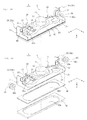
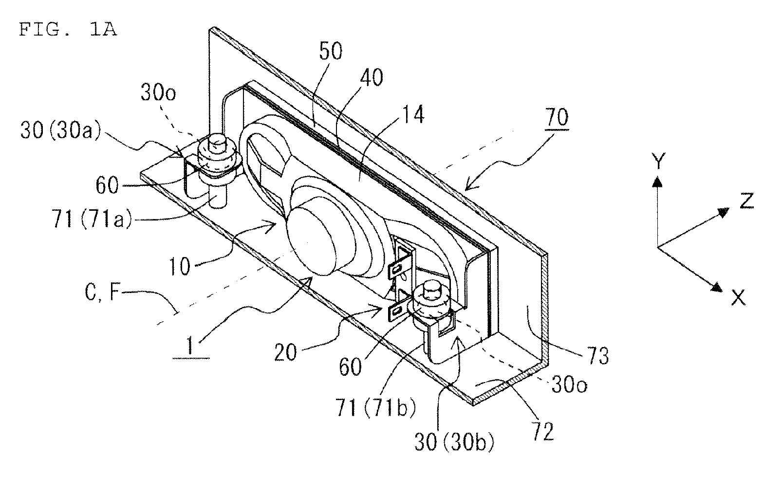
FIG. 1A is a perspective view showing a schematic configuration of a speaker and an apparatus body according to a preferred embodiment of the present invention in a state in which the speaker is attached to the apparatus body, andFIG. 1B is a perspective view in a state in which the speaker ofFig. 1A is removed from the apparatus body. -
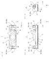
FIG. 2A is a perspective view of the speaker ofFigs. 1A and 1B as seen from the back side, andFIG. 2B is an exploded perspective view of the speaker ofFigs. 1A and 1B as seen from the back side. -
FIG. 3A is a perspective view of the speaker ofFigs. 1A and 1B as seen from the front side, andFIG. 3B is an exploded perspective view of the speaker ofFigs. 1A and 1B as seen from the front side. -
FIG. 4A is a partial plan view of the speaker ofFigs. 1A and 1B as seen from the back side,FIG. 4B is a side view of the speaker ofFigs. 1A and 1B , andFIG. 4C is a side view of the speaker ofFigs. 1A and 1B as seen from another direction. -
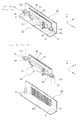
FIG. 5A is a perspective view showing a schematic configuration of a conventional speaker and an apparatus body in a state in which the speaker is attached to the apparatus body, andFIG. 5B is a perspective view in a state in which the speaker ofFig. 5A is removed from the apparatus body. -
FIG. 6A is a perspective view of the speaker ofFigs. 5A and 5B as seen from the back side, andFIG. 6B is an exploded perspective view of the speaker ofFigs. 5A and 5B as seen from the front side. -
FIG. 7A is a perspective view of the speaker ofFigs. 5A and 5B as seen from the front side, andFIG. 7B is an exploded perspective view of the speaker ofFigs. 5A and 5B as seen from the front side. - A speaker according to a preferred embodiment of the present invention will be described below with reference to figures.
FIGs. 1A, 1B ,2A, 2B ,3A, 3B ,4A, 4B, and 4C show the configuration of the speaker according to the present preferred embodiment. Thespeaker 1 is a device that is mounted on an electronic apparatus such as a television receiver and that converts an electrical signal into sound and outputs the sound. Thespeaker 1 is attached to anapparatus body 70 and mounted on an electronic apparatus. Theapparatus body 70 is a case for an electronic apparatus, for example. - The
speaker 1 preferably includes a speakermain body 10 that converts an electrical signal into sound and outputs the sound, an electricalsignal input part 20 to input an electrical signal that is to be converted into sound, and a pair of attachment parts 30 (30a and 30b) to attach the speakermain body 10 to theapparatus body 70. - The speaker
main body 10 includes apermanent magnet 11, avoice coil 12, adiaphragm 13, and aframe 14 and has a configuration in which thepermanent magnet 11, thevoice coil 12, and thediaphragm 13 are supported on theframe 14. - The
frame 14 preferably is formed from a metal plate. Theframe 14 preferably is formed in a shape that surrounds thediaphragm 13, and thediaphragm 13 is disposed within a space surrounded by theframe 14. Theframe 14 includes a sound releasing opening 14o to release the sound generated by the vibration of thediaphragm 13 to the outside of thespeaker 1. The sound releasing opening 14o is provided on the front side of thediaphragm 13, so the front side of thediaphragm 13 faces the sound releasing opening 14o. Thepermanent magnet 11 and thevoice coil 12 are provided on the back side of thediaphragm 13. The sound generated by the vibration of thediaphragm 13 is released to the outside of thespeaker 1 from the sound releasing opening 14o. - In the speaker
main body 10, the side on which the sound releasing opening 14o is provided (the side on which thediaphragm 13 faces the sound releasing opening 14o and the side on which the sound generated by the vibration of thediaphragm 13 is released from the sound releasing opening 14o) is the front side of the speakermain body 10, and the side opposite from the front side of the speaker main body 10 (the side on which thepermanent magnet 11 is provided) is the back side of the speakermain body 10. The surface on the front side of the speaker main body 10 (the surface on the front side of the frame 14) preferably has a planar shape and constitutes a planar surface that is perpendicular or substantially perpendicular to the direction from the back side toward the front side of the speakermain body 10. The direction indicated by arrow Z in the figures is the direction from the back side toward the front side of the speakermain body 10. - The speaker
main body 10 preferably has a shape having the long-side direction and the short-side direction within a plane perpendicular or substantially perpendicular to the direction from the back side toward the front side of the speakermain body 10. That is, the speakermain body 10 preferably has a shape which is long in a given direction (long-side direction) and which is short in a direction perpendicular or substantially perpendicular to this direction (short-side direction) within a plane perpendicular or substantially perpendicular to the direction from the back side toward the front side of the speakermain body 10. The direction parallel or substantially parallel to the direction indicated by arrow X in the figures is the long-side direction of the speakermain body 10, while the direction parallel or substantially parallel to the direction indicated by arrow Y in the figures is the short-side direction of the speakermain body 10. - Furthermore, when the straight line passing through the center of the speaker
main body 10 from the back side toward the front side of the speakermain body 10 is taken as the centerline C, the speakermain body 10 is configured in a shape having rotational symmetry about a 180-degree rotation with the centerline C as the axis of rotation. - The electrical
signal input part 20 preferably has a configuration in whichconductive input terminals 21 are provided on an insulatingterminal stand 22 and is attached to theframe 14. The electricalsignal input part 20 is disposed on the back side of the speakermain body 10 beside thepermanent magnet 11 in the long-side direction of the speakermain body 10. Electrical signal lines for transmission (not illustrated) for transmission from theinput terminals 21 to thevoice coil 12 an electrical signal to be converted into sound are connected between theinput terminals 21 and thevoice coil 12. Electrical signal lines (not illustrated) for input into thespeaker 1 an electrical signal to be converted into sound are connected to theinput terminals 21. - The
attachment part 30a is provided at the side end on one side of the speakermain body 10 in the long-side direction, and theattachment part 30b is provided at the side end on the other side of the speakermain body 10 in the long-side direction. Each of theattachment parts main body 10 on the back side of the speakermain body 10. Fitted holes 30o for being fitted over projectingparts 71 provided on theapparatus body 70 are respectively provided in theattachment parts - Each of the
attachment parts rearward extension part 31 and aninward extension part 32. Therearward extension parts 31 respectively extend toward the back of the speakermain body 10 from the side ends of theframe 14 in the long-side direction of the speakermain body 10. Theinward extension parts 32 respectively extend toward the inside of the speakermain body 10 from therearward extension parts 31 on the back side of the speakermain body 10. Portions of theinward extension parts 32 overlap with the speakermain body 10 on the back side of the speakermain body 10. The fitted holes 30o are provided in theinward extension parts 32. - The
rearward extension parts 31 and the inward extension parts 32 (i.e., theattachment parts frame 14 so as to define a unitary monolithic member. Therearward extension parts 31 are preferably formed by being bent at a bending angle of 90 degrees or approximately 90 degrees from the side ends of theframe 14 in the long-side direction of the speakermain body 10 toward the back of the speakermain body 10. Theinward extension parts 32 are preferably formed by being bent at a bending angle of 90 degrees or approximately 90 degrees from therearward extension parts 31 toward the inside of the speakermain body 10 such that the bend lines created by bending are parallel or substantially parallel to the direction of extension of the rearward extension parts 31 (i.e., the direction from the back side toward the front side of the speaker main body 10). - The fitted hole 30o in the
attachment part 30a and the fitted hole 30o in theattachment part 30b are provided in positions in which the distance from the front surface of the speaker main body 10 (the front surface of the frame 14) is equal or substantially equal with respect to the direction parallel or substantially parallel to the direction from the back side toward the front side of the speakermain body 10. Moreover, the fitted hole 30o in theattachment part 30a and the fitted hole 30o in theattachment part 30b are provided in positions of symmetry with respect to the long-side direction of the speakermain body 10. Specifically, the fitted hole 30o in theattachment part 30a and the fitted hole 30o in theattachment part 30b are provided in positions in which the distance from the centerline C passing through the center of the speakermain body 10 from the back side toward the front side of the speakermain body 10 is equal or substantially equal with respect to the long-side direction of the speakermain body 10. In addition, the fitted hole 30o in theattachment part 30a and the fitted hole 30o in theattachment part 30b are both provided in the center position in the short-side direction of the speakermain body 10 with respect to the short-side direction of the speakermain body 10. - Accordingly, the fitted hole 30o in the
attachment part 30a and the fitted hole 30o in theattachment part 30b are provided in positions of rotational symmetry about a 180-degree rotation with the centerline C passing through the center of the speakermain body 10 from the back side toward the front side of the speakermain body 10 as the rotational axis. - The
apparatus body 70 will now be described. Theapparatus body 70 preferably includes a pair of projecting parts 71 (71a and 71b), abottom wall 72, and afront wall 73. As was described above, theapparatus body 70 is a case for an electronic apparatus, for example. The pair of projecting parts 71 (71a and 71b), thebottom wall 72, and thefront wall 73 are preferably formed as an integral unit from a resin so as to define a unitary monolithic member. - The
front wall 73 rises vertically from thebottom wall 72. Thefront wall 73 preferably includes a sound passing part 73o including numerous fine holes for passing sound emitted from thespeaker 1. The sound passing part 73o preferably is formed such that the distance from the center of the sound passing part 73o to thebottom wall 72 is equal or substantially equal to the distance from the center of the speakermain body 10 to either end edge of the speaker main body 10 (frame 14) in the short-side direction. - Each of the projecting
parts bottom wall 72. Specifically, the projectingparts front wall 73 as well. The space between the projectingpart 71a and the projectingpart 71b is equal or substantially equal to the space between the fitted hole 30o in theattachment part 30a and the fitted hole 30o in theattachment part 30b of thespeaker 1, and the length of each of the projectingparts bottom wall 72 to the tip end) is longer than the distance from either end edge of the speakermain body 10 in the short-side direction to the fitted holes 30o in theattachment parts - Furthermore, the projecting
parts front wall 73 and provided in positions in which the distance from thefront wall 73 is equal or substantially equal with respect to the direction perpendicular or substantially perpendicular to thefront wall 73. Moreover, the projectingparts parts bottom wall 72 and the front wall 73). That is, the projectingpart 71a and the projectingpart 71b preferably are provided in positions in which the distance from the straight line F passing through the center of the sound passing part 73o perpendicularly or substantially perpendicularly to thefront wall 73 with respect to the direction of alignment of the projectingparts - The
speaker 1 is attached to theapparatus body 70 as a result of the fitted holes 30o in theattachment parts parts 71 of theapparatus body 70 in an attitude in which the front side of the speakermain body 10 is caused to face the front wall 73 (sound passing part 73o) of theapparatus body 70. - Because of the configuration of the fitted holes 30o in the
attachment parts parts attachment parts parts apparatus body 70 using two fitting methods (first and second methods) in which the attitudes of thespeaker 1 are different. - The first fitting method is a fitting method in which the fitted hole 30o in the
attachment part 30a is fitted over the projectingpart 71a of theapparatus body 70, while the fitted hole 30o in theattachment part 30b is fitted over the projectingpart 71b of theapparatus body 70. The attitude of thespeaker 1 in this fitting method is referred to as the first attitude. The second fitting method is a fitting method in which the fitted hole 30o in theattachment part 30b is fitted over the projectingpart 71a of theapparatus body 70, while the fitted hole 30o in theattachment part 30a is fitted over the projectingpart 71b of theapparatus body 70. The attitude of thespeaker 1 in this fitting method is referred to as the second attitude. The second attitude is an attitude in which thespeaker 1 is rotated by 180 degrees from the first attitude with the centerline C as the axis of rotation. - That is, the pair of
attachment parts attachment parts parts apparatus body 70 in the first attitude of thespeaker 1, and also such that the fitted holes 30o respectively provided in the pair ofattachment parts parts apparatus body 70 in the second attitude of thespeaker 1 in which thespeaker 1 is rotated by 180 degrees from the first attitude with the centerline C as the axis of rotation. - In addition, the
speaker 1 preferably includesheavy attachment paper 40,attachment foam 50, andattachment rubber parts 60 as ancillary elements that are used to attach the speakermain body 10 to theapparatus body 70. - The
heavy attachment paper 40 and theattachment foam 50 are members that are interposed between the front-side portion of the speaker main body 10 (the front-side portion of the frame 14) and thefront wall 73 of theapparatus body 70 such that no gap is created between the front-side portion of the speaker main body 10 (the front-side portion of the frame 14) and thefront wall 73 of theapparatus body 70 when thespeaker 1 is attached to theapparatus body 70. - The
heavy attachment paper 40 preferably has a uniform or substantially uniform thickness, and an opening 40o is formed in the center. Theheavy attachment paper 40 is bonded to the front-side portion of the speaker main body 10 (the front-side portion of the frame 14) such that the opening 40o coincides with the sound releasing opening 14o in theframe 14. - The
attachment foam 50 preferably has a uniform thickness, and an opening 50o is formed in the center. Theattachment foam 50 is bonded to theheavy attachment paper 40 such that the opening 50o coincides with the opening 40o in theheavy attachment paper 40. That is, theattachment foam 50 is bonded to the front-side portion of the speaker main body 10 (the front-side portion of the frame 14) via theheavy attachment paper 40 such that the opening 50o coincides with the sound releasing opening 14o in theframe 14. - The thicknesses of the
heavy attachment paper 40 andattachment foam 50 are set at dimensions at which theattachment foam 50 is pressed against thefront wall 73 of theapparatus body 70 via theheavy attachment paper 40 by the speakermain body 10 when thespeaker 1 is attached to theapparatus body 70. - The
attachment rubber parts 60 are members that are respectively interposed between the fitted holes 30o in theattachment parts 30 and the projectingparts 71 of theapparatus body 70 such that no gap is produced between the fitted holes 30o in theattachment parts 30 and the projectingparts 71 of theapparatus body 70 when thespeaker 1 is attached to theapparatus body 70. Each of theattachment rubber parts 60 preferably is circular cylindrical or substantially circular cylindrical in shape, and a through-hole 60o is formed therein. Theattachment rubber parts 60 are designed to be attached to and removed from the fitted holes 30o in theattachment parts 30 by being deformed. - Next, a non-limiting example of a method for attaching the
speaker 1 to theapparatus body 70 will be described. Thespeaker 1 is attached to theapparatus body 70 as follows. - First, the
attachment rubber parts 60 are respectively fitted into the fitted holes 30o in theattachment parts 30, thus attaching theattachment rubber parts 60 to theattachment parts 30. Subsequently, the fitted holes 30o in theattachment parts 30 are respectively fitted over the projectingparts 71 of theapparatus body 70 in a state in which theattachment rubber parts 60 are attached to theattachment parts 30. Specifically, the through-holes 60o in theattachment rubber parts 60 attached to theattachment parts 30 are fitted over the projectingparts 71 of theapparatus body 70. At this point, with the front side of the speakermain body 10 being caused to face the front wall 73 (sound passing part 73o) of theapparatus body 70, the through-holes 60o in theattachment rubber parts 60 attached to theattachment parts 30 are fitted over the projectingparts 71 of theapparatus body 70 in the first attitude or second attitude while theattachment foam 50 is pressed against thefront wall 73 of theapparatus body 70. - Then, in a state in which the through-holes 60o in the
attachment rubber parts 60 attached to theattachment parts 30 are fitted over the projectingparts 71 of theapparatus body 70, thespeaker 1 is pushed toward thebottom wall 72, thus causing an end edge of the speaker main body 10 (frame 14) in the short-side direction to contact thebottom wall 72 of theapparatus body 70. Consequently, thespeaker 1 is attached to theapparatus body 70. Thespeaker 1 is attached to theapparatus body 70 in this manner. - In a state in which the
speaker 1 is attached to theapparatus body 70, theattachment foam 50 is interposed in a compressed state between the front-side portion of the speaker main body 10 (the front-side portion of the frame 14) and thefront wall 73 of theapparatus body 70, and theattachment rubber parts 60 are respectively interposed between the fitted holes 30o provided in theattachment parts 30 and the projectingparts 71 provided on theapparatus body 70. - Note that in
FIGS. 1A and 1B , a case is illustrated in which thespeaker 1 is attached to theapparatus body 70 in the first attitude (with the fitted hole 30o in theattachment part 30a being fitted over the projectingpart 71a and the fitted hole 30o in theattachment part 30b being fitted over the projectingpart 71b). If thespeaker 1 is attached to theapparatus body 70 in the second attitude (with the fitted hole 30o in theattachment part 30b being fitted over the projectingpart 71a and the fitted hole 30o in theattachment part 30a being fitted over the projectingpart 71b), then the position (and direction) of the electricalsignal input part 20 will be reversed compared to the case of the attachment in the first attitude. - With the
speaker 1 having such a configuration, theattachment parts 30 are preferably arranged so as to partially overlap with the speakermain body 10 on the back side of the speakermain body 10, so the size of thespeaker 1 can be reduced, which makes it possible to reduce the space required for the attachment to theapparatus body 70. Consequently, the degree of freedom in the designing of electronic apparatuses on which thespeaker 1 is mounted is increased, which can improve the design characteristics of electronic apparatuses on which thespeaker 1 is mounted. - Furthermore, the
inward extension parts 32 of theattachment parts 30 respectively provided with the fitted holes 30o are bent such that the bent lines created by bending are parallel to the direction of extension of the rearward extension parts 31 (i.e., the direction from the back side toward the front side of the speaker main body 10). For this reason, the speakermain body 10 is attached to theapparatus body 70 in a proper attitude in which the direction from the back side toward the front side of the speakermain body 10 is a proper direction (direction perpendicular or substantially perpendicular to the front wall 73) even in cases where the bending precision of theinward extension parts 32 is poor, causing the angle of bending of theinward extension parts 32 to be shifted from the proper angle (90 degrees), or in cases where unnecessary force is applied when the fitted holes 30o in theinward extension parts 32 are fitted over the projectingparts 71 of theapparatus body 70, causing the angle of bending of theinward extension parts 32 to be altered from the proper angle. Consequently, theattachment foam 50 can be pressed against thefront wall 73 of theapparatus body 70 with a uniform force, which makes it possible to prevent deterioration of the quality and pressure of the sound that is output from thespeaker 1 and to ensure stable sound quality and sound pressure. - Moreover, the speaker
main body 10 preferably has a shape having rotational symmetry about a 180-degree rotation with the centerline C passing through the center of the speakermain body 10 from the back side toward the front side of the speakermain body 10 being taken as the axis of rotation. Then, the pair ofattachment parts attachment parts parts apparatus body 70 in the specified first attitude of thespeaker 1 and also such that the fitted holes 30o respectively provided in the pair ofattachment parts parts apparatus body 70 in the second attitude in which thespeaker 1 is rotated by 180 degrees from the first attitude with the centerline C as the axis of rotation. Consequently, in cases where twospeakers 1 are mounted on the left and right of an electronic apparatus, thespeakers 1 can be shared between the left and right. That is, when twospeakers 1 are mounted on the left and right of an electronic apparatus, it is possible to use the same type of speaker for thespeakers 1. - Note that the present invention is not limited to the configuration of the aforementioned preferred embodiment, and various modifications are possible. For example, with regard to the attachment parts, attachment parts formed from a resin may be attached to the frame of the speaker main body. In addition, the frame of the speaker main body may be formed from a resin. In this case, the attachment parts may be formed from a resin integrally with the frame, or attachment parts formed from metal plates may be attached to the frame.
- Furthermore, the attachment foam may be bonded to the front wall of the apparatus body as part of the apparatus body. In this case, the heavy attachment paper may be bonded to the front-side portion of the speaker main body (the front-side portion of the frame) or may also be bonded as part of the apparatus body to the attachment foam that is bonded to the front wall of the apparatus body. Moreover, it would also be possible not to provide any heavy attachment paper. In this case, the attachment foam may be bonded directly to the front-side portion of the speaker main body (the front-side portion of the frame) or may also be bonded to the front wall of the apparatus body as part of the apparatus body. In addition, the attachment rubber parts may be provided on the projecting parts of the apparatus body as part of the apparatus body. In this case, the attachment rubber parts may be formed integrally with the projecting parts as part of the projecting parts. Furthermore, the apparatus body may also be configured as a separate body from a case for an electronic apparatus.
- While preferred embodiments of the present invention have been described above, it is to be understood that variations and modifications will be apparent to those skilled in the art without departing from the scope and spirit of the present invention. The scope of the present invention, therefore, is to be determined solely by the following claims.
Claims (6)
- A speaker comprising:a speaker main body including:a frame;a permanent magnet;a voice coil;a diaphragm; andan attachment part including a fitting hole and arranged to attach the speaker main body to an apparatus body; whereinthe permanent magnet, the voice coil and the diaphragm are supported on the frame; whereinthe speaker main body is configured to be attached to the apparatus body as a result of the fitted hole provided in the attachment part being fitted over a projecting part provided on the apparatus body; andthe attachment part is arranged such that at least a portion thereof overlaps with the speaker main body on a back side of the speaker main body.
- The speaker according to claim 1, further comprising attachment foam interposed between a front-side portion of the speaker main body and the apparatus body to assist in attaching the speaker main body to the apparatus body.
- The speaker according to claim 1, further comprising an attachment rubber part interposed between the fitted hole provided in the attachment part and the projecting part provided on the apparatus body as an ancillary part to assist in attaching the speaker main body to the apparatus body.
- The speaker according to claim 1, wherein the attachment part is defined by a metal plate and includes a rearward extension part that extends toward a back side of the speaker main body and an inward extension part that extends toward an inside of the speaker main body on the back side of the speaker main body by being bent from the rearward extension part toward the inside of the speaker main body such that a bend line created by bending is parallel or substantially parallel to a direction of extension of the rearward extension part; wherein
at least a portion of the inward extension part overlaps with the speaker main body on the back side of the speaker main body; and
the fitted hole is provided in the inward extension part. - The speaker according to claim 1, wherein
the frame is defined by a metal plate;
the attachment part is defined by the metal plate and is integral with the frame such that the frame and attachment part are defined by a single unitary monolithic member;
the attachment part includes:a rearward extension part that extends toward a back of the speaker main body by being bent from the frame toward the back of the speaker main body; andan inward extension part that extends toward an inside of the speaker main body on the back side of the speaker main body by being bent from the rearward extension part toward the inside of the speaker main body such that a bend line created by bending is parallel or substantially parallel to a direction of extension of the rearward extension part; whereinat least a portion of the inward extension part overlaps with the speaker main body on a back side of the speaker main body; andthe fitted hole is provided in the inward extension part. - The speaker according to claim 1, wherein assuming a straight line passing though a center of the speaker main body from a back side toward a front side of the speaker main body is taken as a centerline, the speaker main body has a shape having rotational symmetry about a 180-degree rotation with the centerline as an axis of rotation;
the attachment part is provided in a pair;
the fitted hole is provided in each of the pair of attachment parts; and
the pair of attachment parts are configured such that the fitted holes respectively provided in the pair of attachment parts are arranged to be respectively fitted over a pair of projecting parts provided on the apparatus body in a specified first attitude of the speaker, and also such that the fitted holes respectively provided in the pair of attachment parts are arranged to be respectively fitted over the pair of projecting parts provided on the apparatus body in a second attitude of the speaker as well in which the speaker is rotated by 180 degrees from the first attitude with the centerline as the axis of rotation.
Applications Claiming Priority (1)
| Application Number | Priority Date | Filing Date | Title |
|---|---|---|---|
| JP2011206098A JP2013070160A (en) | 2011-09-21 | 2011-09-21 | Speaker |
Publications (2)
| Publication Number | Publication Date |
|---|---|
| EP2574081A2 true EP2574081A2 (en) | 2013-03-27 |
| EP2574081A3 EP2574081A3 (en) | 2014-02-19 |
Family
ID=46851846
Family Applications (1)
| Application Number | Title | Priority Date | Filing Date |
|---|---|---|---|
| EP12184153.0A Withdrawn EP2574081A3 (en) | 2011-09-21 | 2012-09-13 | Speaker |
Country Status (3)
| Country | Link |
|---|---|
| US (1) | US20130070956A1 (en) |
| EP (1) | EP2574081A3 (en) |
| JP (1) | JP2013070160A (en) |
Cited By (1)
| Publication number | Priority date | Publication date | Assignee | Title |
|---|---|---|---|---|
| EP2905973A1 (en) * | 2014-02-07 | 2015-08-12 | LG Electronics Inc. | Speaker assembly embedded in an electronic device |
Families Citing this family (11)
| Publication number | Priority date | Publication date | Assignee | Title |
|---|---|---|---|---|
| US9984583B2 (en) * | 2013-09-20 | 2018-05-29 | Bose Corporation | Audio demonstration kit |
| CN103747398B (en) * | 2013-12-25 | 2017-05-17 | 歌尔股份有限公司 | Loudspeaker module and electronic device comprising the loudspeaker module |
| JP2016021738A (en) * | 2014-06-18 | 2016-02-04 | シャープ株式会社 | Display device, television receiver, and manufacturing method of display device |
| CN104113613A (en) * | 2014-07-02 | 2014-10-22 | 深圳市财富之舟科技有限公司 | Mobile phone and method for manufacturing mobile phone |
| CN204733358U (en) | 2015-07-01 | 2015-10-28 | 歌尔声学股份有限公司 | Microspeaker |
| CN207251842U (en) * | 2017-09-29 | 2018-04-17 | 京东方科技集团股份有限公司 | A kind of loudspeaker box fixed structure and display device |
| CN108174338A (en) * | 2017-12-21 | 2018-06-15 | 瑞声科技(新加坡)有限公司 | Loudspeaker enclosure and its assembly method |
| US11140488B2 (en) * | 2018-05-22 | 2021-10-05 | B&W Group Ltd. | Speaker-driver cone with increased stiffness |
| KR20230105128A (en) | 2022-01-03 | 2023-07-11 | 삼성전자주식회사 | Display apparutus |
| FR3158005A1 (en) * | 2024-01-03 | 2025-07-04 | Sagemcom Broadband Sas | Speaker bowl |
| KR102868086B1 (en) * | 2024-01-16 | 2025-10-01 | 엘지전자 주식회사 | Sound device and display device including it |
Citations (2)
| Publication number | Priority date | Publication date | Assignee | Title |
|---|---|---|---|---|
| JP2008258753A (en) | 2007-04-02 | 2008-10-23 | Funai Electric Co Ltd | Panel type television, and fitting structure of speaker unit |
| JP2011019170A (en) | 2009-07-10 | 2011-01-27 | Funai Electric Co Ltd | Speaker mounting structure |
Family Cites Families (6)
| Publication number | Priority date | Publication date | Assignee | Title |
|---|---|---|---|---|
| JPH0235597U (en) * | 1988-08-26 | 1990-03-07 | ||
| DE4133412A1 (en) * | 1991-10-09 | 1992-03-05 | Dieter Rothaermel | Loudspeaker housing with reduced characteristic resonance - has apertured housing walls with foam layers providing separation from adjacent components |
| KR100327357B1 (en) * | 1999-04-16 | 2002-03-06 | 구자홍 | speaker system in video display appliance |
| US6866116B2 (en) * | 2002-11-20 | 2005-03-15 | Meiloon Industrial Co., Ltd. | Structure for quick-assembly cabinet |
| TWI315642B (en) * | 2006-08-02 | 2009-10-01 | Au Optronics Corp | Auxiliary fastening device for assisting transducer being fastened and isolating vibration induced during operation of transducer |
| JP2011182050A (en) * | 2010-02-26 | 2011-09-15 | Hitachi Consumer Electronics Co Ltd | Video display device |
-
2011
- 2011-09-21 JP JP2011206098A patent/JP2013070160A/en active Pending
-
2012
- 2012-09-12 US US13/611,732 patent/US20130070956A1/en not_active Abandoned
- 2012-09-13 EP EP12184153.0A patent/EP2574081A3/en not_active Withdrawn
Patent Citations (2)
| Publication number | Priority date | Publication date | Assignee | Title |
|---|---|---|---|---|
| JP2008258753A (en) | 2007-04-02 | 2008-10-23 | Funai Electric Co Ltd | Panel type television, and fitting structure of speaker unit |
| JP2011019170A (en) | 2009-07-10 | 2011-01-27 | Funai Electric Co Ltd | Speaker mounting structure |
Cited By (7)
| Publication number | Priority date | Publication date | Assignee | Title |
|---|---|---|---|---|
| EP2905973A1 (en) * | 2014-02-07 | 2015-08-12 | LG Electronics Inc. | Speaker assembly embedded in an electronic device |
| US10028044B2 (en) | 2014-02-07 | 2018-07-17 | Lg Electronics Inc. | Electronic device including a speaker assembly |
| US10299022B2 (en) | 2014-02-07 | 2019-05-21 | Lg Electronics Inc. | Electronic device including a speaker assembly |
| US10959000B2 (en) | 2014-02-07 | 2021-03-23 | Lg Electronics Inc. | Electronic device including a speaker assembly |
| US11310577B2 (en) | 2014-02-07 | 2022-04-19 | Lg Electronics Inc. | Electronic device |
| US11665458B2 (en) | 2014-02-07 | 2023-05-30 | Lg Electronics Inc. | Electronic device |
| US12069417B2 (en) | 2014-02-07 | 2024-08-20 | Lg Electronics Inc. | Electronic device |
Also Published As
| Publication number | Publication date |
|---|---|
| EP2574081A3 (en) | 2014-02-19 |
| JP2013070160A (en) | 2013-04-18 |
| US20130070956A1 (en) | 2013-03-21 |
Similar Documents
| Publication | Publication Date | Title |
|---|---|---|
| US20130070956A1 (en) | Speaker | |
| CN101267465B (en) | Electronic device and case | |
| CN103444202B (en) | Loud speaker, the electronic equipment employing this loud speaker and mobile body device | |
| WO2010046988A1 (en) | Speaker unit | |
| US11032658B2 (en) | Speaker | |
| CN107072096B (en) | Cable support | |
| US20080002850A1 (en) | Speaker and manufacturing method | |
| CN111630713B (en) | Vehicle-mounted antenna device | |
| CN206948600U (en) | A kind of electroacoustic transducer and electronic equipment | |
| US20130044419A1 (en) | Electronic device | |
| US8870509B2 (en) | Attachment structure and display apparatus | |
| JP2006229519A (en) | Frame for speaker device and speaker device | |
| US12149908B2 (en) | Sound device | |
| US9918153B2 (en) | Mobile terminal | |
| US20090065673A1 (en) | Speaker holder | |
| JP6024680B2 (en) | Connector support structure | |
| JP2009163990A (en) | Electronic system | |
| US12526560B2 (en) | Speaker box | |
| CN101946374B (en) | Backlight device, display and television receiver | |
| US20240406639A1 (en) | Speaker | |
| CN214589223U (en) | Antenna components and mobile terminals | |
| JP6204784B2 (en) | Connection port device | |
| JP2007035376A (en) | Electronic equipment | |
| JP2010056448A (en) | Ground connection structure | |
| JP2021048040A (en) | Panel mounting type connector |
Legal Events
| Date | Code | Title | Description |
|---|---|---|---|
| PUAI | Public reference made under article 153(3) epc to a published international application that has entered the european phase |
Free format text: ORIGINAL CODE: 0009012 |
|
| AK | Designated contracting states |
Kind code of ref document: A2 Designated state(s): AL AT BE BG CH CY CZ DE DK EE ES FI FR GB GR HR HU IE IS IT LI LT LU LV MC MK MT NL NO PL PT RO RS SE SI SK SM TR |
|
| AX | Request for extension of the european patent |
Extension state: BA ME |
|
| PUAL | Search report despatched |
Free format text: ORIGINAL CODE: 0009013 |
|
| AK | Designated contracting states |
Kind code of ref document: A3 Designated state(s): AL AT BE BG CH CY CZ DE DK EE ES FI FR GB GR HR HU IE IS IT LI LT LU LV MC MK MT NL NO PL PT RO RS SE SI SK SM TR |
|
| AX | Request for extension of the european patent |
Extension state: BA ME |
|
| 17P | Request for examination filed |
Effective date: 20140806 |
|
| RBV | Designated contracting states (corrected) |
Designated state(s): AL AT BE BG CH CY CZ DE DK EE ES FI FR GB GR HR HU IE IS IT LI LT LU LV MC MK MT NL NO PL PT RO RS SE SI SK SM TR |
|
| 17Q | First examination report despatched |
Effective date: 20141222 |
|
| STAA | Information on the status of an ep patent application or granted ep patent |
Free format text: STATUS: THE APPLICATION IS DEEMED TO BE WITHDRAWN |
|
| 18D | Application deemed to be withdrawn |
Effective date: 20150505 |