EP2574058A2 - Projector - Google Patents
Projector Download PDFInfo
- Publication number
- EP2574058A2 EP2574058A2 EP12183524A EP12183524A EP2574058A2 EP 2574058 A2 EP2574058 A2 EP 2574058A2 EP 12183524 A EP12183524 A EP 12183524A EP 12183524 A EP12183524 A EP 12183524A EP 2574058 A2 EP2574058 A2 EP 2574058A2
- Authority
- EP
- European Patent Office
- Prior art keywords
- image
- information
- scanning
- position acquisition
- laser beam
- Prior art date
- Legal status (The legal status is an assumption and is not a legal conclusion. Google has not performed a legal analysis and makes no representation as to the accuracy of the status listed.)
- Withdrawn
Links
Images


Classifications
-
- G—PHYSICS
- G06—COMPUTING OR CALCULATING; COUNTING
- G06F—ELECTRIC DIGITAL DATA PROCESSING
- G06F3/00—Input arrangements for transferring data to be processed into a form capable of being handled by the computer; Output arrangements for transferring data from processing unit to output unit, e.g. interface arrangements
- G06F3/01—Input arrangements or combined input and output arrangements for interaction between user and computer
- G06F3/03—Arrangements for converting the position or the displacement of a member into a coded form
- G06F3/041—Digitisers, e.g. for touch screens or touch pads, characterised by the transducing means
- G06F3/0416—Control or interface arrangements specially adapted for digitisers
- G06F3/0418—Control or interface arrangements specially adapted for digitisers for error correction or compensation, e.g. based on parallax, calibration or alignment
-
- G—PHYSICS
- G03—PHOTOGRAPHY; CINEMATOGRAPHY; ANALOGOUS TECHNIQUES USING WAVES OTHER THAN OPTICAL WAVES; ELECTROGRAPHY; HOLOGRAPHY
- G03B—APPARATUS OR ARRANGEMENTS FOR TAKING PHOTOGRAPHS OR FOR PROJECTING OR VIEWING THEM; APPARATUS OR ARRANGEMENTS EMPLOYING ANALOGOUS TECHNIQUES USING WAVES OTHER THAN OPTICAL WAVES; ACCESSORIES THEREFOR
- G03B21/00—Projectors or projection-type viewers; Accessories therefor
- G03B21/14—Details
-
- G—PHYSICS
- G06—COMPUTING OR CALCULATING; COUNTING
- G06F—ELECTRIC DIGITAL DATA PROCESSING
- G06F3/00—Input arrangements for transferring data to be processed into a form capable of being handled by the computer; Output arrangements for transferring data from processing unit to output unit, e.g. interface arrangements
- G06F3/01—Input arrangements or combined input and output arrangements for interaction between user and computer
- G06F3/03—Arrangements for converting the position or the displacement of a member into a coded form
- G06F3/041—Digitisers, e.g. for touch screens or touch pads, characterised by the transducing means
- G06F3/042—Digitisers, e.g. for touch screens or touch pads, characterised by the transducing means by opto-electronic means
- G06F3/0425—Digitisers, e.g. for touch screens or touch pads, characterised by the transducing means by opto-electronic means using a single imaging device like a video camera for tracking the absolute position of a single or a plurality of objects with respect to an imaged reference surface, e.g. video camera imaging a display or a projection screen, a table or a wall surface, on which a computer generated image is displayed or projected
-
- G—PHYSICS
- G09—EDUCATION; CRYPTOGRAPHY; DISPLAY; ADVERTISING; SEALS
- G09G—ARRANGEMENTS OR CIRCUITS FOR CONTROL OF INDICATING DEVICES USING STATIC MEANS TO PRESENT VARIABLE INFORMATION
- G09G3/00—Control arrangements or circuits, of interest only in connection with visual indicators other than cathode-ray tubes
- G09G3/02—Control arrangements or circuits, of interest only in connection with visual indicators other than cathode-ray tubes by tracing or scanning a light beam on a screen
- G09G3/025—Control arrangements or circuits, of interest only in connection with visual indicators other than cathode-ray tubes by tracing or scanning a light beam on a screen with scanning or deflecting the beams in two directions or dimensions
-
- H—ELECTRICITY
- H04—ELECTRIC COMMUNICATION TECHNIQUE
- H04N—PICTORIAL COMMUNICATION, e.g. TELEVISION
- H04N9/00—Details of colour television systems
- H04N9/12—Picture reproducers
- H04N9/31—Projection devices for colour picture display, e.g. using electronic spatial light modulators [ESLM]
- H04N9/3129—Projection devices for colour picture display, e.g. using electronic spatial light modulators [ESLM] scanning a light beam on the display screen
-
- H—ELECTRICITY
- H04—ELECTRIC COMMUNICATION TECHNIQUE
- H04N—PICTORIAL COMMUNICATION, e.g. TELEVISION
- H04N9/00—Details of colour television systems
- H04N9/12—Picture reproducers
- H04N9/31—Projection devices for colour picture display, e.g. using electronic spatial light modulators [ESLM]
- H04N9/3179—Video signal processing therefor
- H04N9/3185—Geometric adjustment, e.g. keystone or convergence
-
- H—ELECTRICITY
- H04—ELECTRIC COMMUNICATION TECHNIQUE
- H04N—PICTORIAL COMMUNICATION, e.g. TELEVISION
- H04N9/00—Details of colour television systems
- H04N9/12—Picture reproducers
- H04N9/31—Projection devices for colour picture display, e.g. using electronic spatial light modulators [ESLM]
- H04N9/3191—Testing thereof
- H04N9/3194—Testing thereof including sensor feedback
-
- G—PHYSICS
- G09—EDUCATION; CRYPTOGRAPHY; DISPLAY; ADVERTISING; SEALS
- G09G—ARRANGEMENTS OR CIRCUITS FOR CONTROL OF INDICATING DEVICES USING STATIC MEANS TO PRESENT VARIABLE INFORMATION
- G09G2320/00—Control of display operating conditions
- G09G2320/02—Improving the quality of display appearance
- G09G2320/028—Improving the quality of display appearance by changing the viewing angle properties, e.g. widening the viewing angle, adapting the viewing angle to the view direction
-
- G—PHYSICS
- G09—EDUCATION; CRYPTOGRAPHY; DISPLAY; ADVERTISING; SEALS
- G09G—ARRANGEMENTS OR CIRCUITS FOR CONTROL OF INDICATING DEVICES USING STATIC MEANS TO PRESENT VARIABLE INFORMATION
- G09G2340/00—Aspects of display data processing
- G09G2340/14—Solving problems related to the presentation of information to be displayed
Definitions
- the present invention relates to a projector including a laser beam generation portion.
- a projector including a laser beam generation portion is known in general, as disclosed in Japanese Patent Laying-Open No. 2010-243808 , for example.
- the aforementioned Japanese Patent Laying-Open No. 2010-243808 discloses a projector including a laser beam source (laser beam generation portion) outputting a laser beam, a scanner mirror (scanning portion) scanning the laser beam, a photosensor (photoreceiving portion) receiving the laser beam reflected by a bar or a pen (detection object) and a CPU (Central Processing Unit) acquiring the position of the bar or the pen on the basis of photoreceiving information of the laser beam received by the photosensor.
- the CPU Central Processing Unit
- the CPU is formed to acquire the position of the bar or the pen by specifying a scanning position of the laser beam with the scanner mirror on the basis of the time when the photosensor has received the reflected laser beam.
- a technique of correcting distortion of a projected image by changing the output timing for a laser beam is also known in general.
- the present invention has been proposed in order to solve the aforementioned problems, and an object of the present invention is to provide a projector capable of accurately acquiring the position of a detection object corresponding to an image whose distortion has been corrected when projecting the image while correcting the distortion.
- a projector includes a laser beam generation portion outputting a laser beam, an image projection portion, including a scanning portion scanning the laser beam, projecting an image on a projection area, an image correction portion correcting distortion of the projected image on the basis of projection condition information, a photoreceiving portion receiving the laser beam reflected by a detection object, and a position acquisition portion acquiring the position of the detection object on the basis of photoreceiving information of the laser beam received by the photoreceiving portion and the projection condition information employed by the image correction portion for correcting the image.
- the projector is provided with the position acquisition portion acquiring the position of the detection object on the basis of the photoreceiving information of the laser beam received by the photoreceiving portion and the projection condition information employed by the image correction portion for correcting the image so that the position acquisition portion can acquire the position of the detection object by employing the projection condition information common to that employed for correcting the image, whereby the position of the detection object can be acquired to correspond to the image whose distortion has been corrected. Consequently, the position of the detection object corresponding to the image whose distortion has been corrected can be accurately acquired when the projector projects the image while correcting the distortion.
- the image correction portion is preferably formed to estimate a scanning locus of the laser beam on the projection area on the basis of image correction information including the projection condition information and to correct the distortion of the projected image on the basis of the estimated scanning locus
- the position acquisition portion is preferably formed to estimate a scanning locus of the laser beam on the projection area on the basis of position acquisition information including the projection condition information and to acquire the position of the detection object on the basis of the estimated scanning locus and the photoreceiving information.
- the position acquisition portion estimates the scanning locus employed for acquiring the position of the detection object on the basis of the same projection condition information as that for the scanning locus employed by the image correction portion for correcting the image, whereby the position acquisition portion can easily accurately acquire the position of the detection object corresponding to the corrected image.
- the projector is preferably so formed as to update the image correction information and the position acquisition information in synchronization with a cycle of natural number times a picture display frame cycle.
- the image correction information and the position acquisition information are not updated in excess of twice in one picture display frame, whereby the position acquisition portion can accurately acquire the position of the detection object corresponding to the corrected image without a complicated position acquisition control operation.
- the aforementioned projector having such a structure that the image correction portion estimates the scanning locus of the laser beam on the projection area on the basis of the image correction information is preferably so formed as to update the image correction information and the position acquisition information in a blanking period.
- the projector updates the image correction information and the position acquisition information in the blanking period when no laser beam is output, whereby the projector can be inhibited from updating the corrected image while scanning one picture display frame, for example.
- the aforementioned projector having such a structure that the image correction portion estimates the scanning locus of the laser beam on the projection area on the basis of the image correction information is preferably so formed as to update the image correction information and the position acquisition information in synchronization with each other.
- the projector can update the scanning locus estimated by the image correction portion on the basis of the image correction information and the scanning locus estimated by the position acquisition portion on the basis of the position acquisition information at identical timing, whereby the position acquisition portion can accurately acquire the position of the detection object corresponding to the corrected image also immediately after the image correction portion corrects the image correspondingly to the updated image correction information.
- the projection condition information preferably includes at least one of a projection angle, a driving frequency for the scanning portion, a scanning angle of the scanning portion, resolution of the image and an aspect ratio of the image.
- the position of the detection object corresponding to the image whose distortion has been corrected can be easily accurately acquired by employing at least one of the projection angle, the driving frequency for the scanning portion, the scanning angle of the scanning portion, the resolution of the image and the aspect ratio of the image in common to the correction of the distortion of the image and the acquisition of the position of the detection object.
- the position acquisition portion is preferably formed not to acquire the position of the detection object until a prescribed time elapses after the updating when the position acquisition information is updated.
- the position acquisition portion can acquire the position of the detection object after movement thereof also when the projector updates the corrected image by updating the image correction information along with the position acquisition information and the user moves the detection object correspondingly to the updated corrected image.
- the position acquisition portion is preferably formed to estimate a scanning locus of the laser beam on the projection area on the basis of a relational expression between time information and image coordinate transformation information derived by employing the position acquisition information and to acquire the position of the detection object corresponding to the corrected image projected in a state where the distortion of the image has been corrected on the basis of the estimated scanning locus and the photoreceiving information.
- the position acquisition portion can easily estimate the scanning locus of the laser beam on the projection area on the basis of the relational expression between the time information and the image coordinate transformation information derived by employing the position acquisition information.
- the image correction portion is preferably formed to estimate a scanning locus of the laser beam on the projection area on the basis of a relational expression between time information and image coordinate transformation information derived by employing the image correction information identical to the position acquisition information and to correct the distortion of the projected image on the basis of the estimated scanning locus.
- the image correction portion and the position acquisition portion estimate the scanning loci on the basis of the relational expression between the time information and the image coordinate transformation information derived by employing the same information, whereby the position acquisition portion can more accurately acquire the position of the detection object corresponding to the corrected image.
- the image correction portion is preferably formed to estimate a scanning locus of the laser beam on the projection area on the basis of the same relational expression as the relational expression between the time information and the image coordinate transformation information employed by the position acquisition portion for estimating the scanning locus of the laser beam on the projection area and to correct the distortion of the projected image on the basis of the estimated scanning locus.
- the scanning loci estimated by the image correction portion and the position acquisition portion respectively are identical to each other, whereby the position acquisition portion can more accurately acquire the position of the detection object corresponding to the corrected image.
- the position acquisition portion is preferably formed to estimate the scanning locus every line for scanning the laser beam. According to this structure, the position acquisition portion estimates the scanning locus every line also when the shape of the line of the scanning locus of the laser beam on the projection area varies with the distance from the projector, whereby the same can accurately acquire the position of the detection object.
- the position acquisition portion is preferably formed to estimate the scanning locus every frame. According to this structure, the position acquisition portion can collectively estimate the scanning locus at a time every frame.
- the position acquisition portion estimates the scanning locus of the laser beam on the projection area on the basis of the relational expression between the time information and the image coordinate transformation information
- the position acquisition portion is preferably formed to estimate the scanning locus by approximating the relational expression between the time information and the image coordinate transformation information. According to this structure, the position acquisition portion can easily estimate the scanning locus of the laser beam on the projection area by approximating the relational expression between the time information and the image coordinate transformation information.
- the position acquisition portion estimates the scanning locus of the laser beam on the projection area on the basis of the relational expression between the time information and the image coordinate transformation information
- the position acquisition portion is preferably formed to derive the relational expression between the time information and the image coordinate transformation information in consideration of a delay time in circuit processing. According to this structure, the position acquisition portion can more accurately acquire the position of the detection object by taking the delay time in circuit processing into consideration.
- the position acquisition portion may be constituted of a control portion.
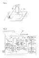
- the projector 100 is formed to be used in a state arranged on a table 1, as shown in Fig. 1 . Further, the projector 100 is formed to project an image 1a on the upper surface of a projection area such as the table 1.
- the table 1 is an example of the "projection area" in the present invention.
- the projector 100 includes a main CPU 101, an operation portion 102, three laser beam sources 103 to 105, two polarizing beam splitters 106 and 107, a lens 180, an image projection portion 109, a display control portion 110 and a pointing detection control portion 120, as shown in Fig. 2 .
- the image projection portion 109 includes an MEMS (Micro Electro Mechanical System) mirror 109a.
- the display control portion 110 includes a picture processing portion 111, a beam source control portion 112, an LD (laser diode) driver 113, a mirror control portion 114 and a mirror driver 115.
- the pointing detection control portion 120 includes a light detection portion 121 and a position acquisition CPU 122.
- the laser beam sources 103 to 105 are examples of the “laser beam generation portion” in the present invention, and the MEMS mirror 109a is an example of the “scanning portion” in the present invention.
- the picture processing portion 111 is an example of the "image correction portion” in the present invention.
- the light detection portion 121 is an example of the “photoreceiving portion” in the present invention, and the position acquisition CPU 122 is an example of the "position acquisition portion” or the "control portion” in the present invention.
- the main CPU 101 is formed to control the respective portions of the projector 100.
- the operation portion 102 is provided for accepting an operation of supplying power to the projector 100, an operation of changing a projection angle for the image 1a and an operation of changing the resolution of the image 1a.
- the laser beam source 103 is formed to apply a blue laser beam to the MEMS mirror 109a through the polarizing beam splitter 106 and the lens 108.
- the laser beam sources 104 and 105 are formed to apply green and red laser beams to the MEMS mirror 109a through the polarizing beam splitters 107 and 106 and the lens 108 respectively.
- the image projection portion 109 is formed to project the image 1a (see Fig. 1 ) on the table 1. More specifically, the MEMS mirror 109a of the image projection portion 109 is formed to project the image 1a on the table 1 by scanning the laser beams emitted from the laser beam sources 103 to 105. The MEMS mirror 109a is formed to scan the laser beams by driving the same on two axes in the horizontal and vertical directions. Further, the MEMS mirror 109a is formed to scan the horizontal direction at a high speed by resonance driving and to scan the vertical direction at a low speed by DC driving.
- the picture processing portion 111 is formed to control projection of a picture on the basis of an externally input picture signal. More specifically, the picture processing portion 111 is formed to control driving of the MEMS mirror 109a through the mirror control portion 114 and to control application of the laser beams by the laser beam sources 103 to 105 through the beam source control portion 112 on the basis of the externally input picture signal. Further, the picture processing portion 111 is formed to correct distortion of the projected image 1a.
- the picture processing portion 111 derives a relational expression (see an expression (7) described below), described later, between time information and image coordinate transformation information on the basis of a projection angle, a driving frequency for the MEMS mirror 109a, a scanning angle of the MEMS mirror 109a, resolution of the image 1a and an aspect ratio of the image 1a. Further, the picture processing portion 111 is formed to estimate scanning loci of the laser beams on the table 1 on the basis of the derived relational expression between the time information and the image coordinate transformation information and to correct distortion of the image 1a on the basis of the estimated scanning loci.
- a relational expression see an expression (7) described below
- the picture processing portion 111 is formed to update information of the projection angle, the driving frequency for the MEMS mirror 109a, the scanning angle of the MEMS mirror 109a, the resolution of the image 1a and the aspect ratio of the image 1a in a blanking period between frames in a cycle of natural number times a frame cycle. Further, the picture processing portion 111 is formed to update the information of the projection angle and the information of the scanning angle of the MEMS mirror 109a when the user changes the projection angle. Further, the picture processing portion 111 is formed to update the information of the resolution of the image 1a and the information of the aspect ratio of the image 1a respectively when the user changes the resolution and the aspect ratio.
- the picture processing portion 111 is formed to update the information of the driving frequency when the resonance frequency of the MEMS mirror 109a fluctuates due to temperature fluctuation or the like. Further, the picture processing portion 111 is formed to be capable of transmitting a synchronizing signal for controlling the position acquisition CPU 122 to update the information of the projection angle, the driving frequency for the MEMS mirror 109a, the scanning angle of the MEMS mirror 109a, the resolution of the image 1a and the aspect ratio of the image 1a.
- the information of the projection angle, the driving frequency for the MEMS mirror 109a, the scanning angle of the MEMS mirror 109a, the resolution of the image 1a and the aspect ratio of the image 1a is an example of the "projection condition information" or the "image correction information" in the present invention.
- the beam source control portion 112 is formed to control the LD driver 113 thereby controlling the emission of the laser beams by the laser beam sources 103 to 105 on the basis of control by the picture processing portion 111. More specifically, the beam source control portion 112 is formed to control the laser beam sources 103 to 105 to emit the laser beams of colors corresponding to respective pixels of the image 1a in synchronization with scanning timing of the MEMS mirror 109a.
- the mirror control portion 114 is formed to control the mirror driver 115 thereby controlling driving of the MEMS mirror 109a on the basis of control by the picture processing portion 111.
- the light detection portion 121 is formed to receive (detect) the laser beams reflected by a touch pen 2, as shown in Fig. 3 .
- the position acquisition CPU 122 is formed to acquire the position of the touch pen 2 on the basis of time information about the time when the light detection portion 121 has detected the reflected laser beams and the scanning loci of the laser beams. More specifically, the position acquisition CPU 122 acquires the position of the touch pen 2 corresponding to the image 1a by specifying on which positions the detected laser beams are scanned with respect to the image 1a on the basis of an elapsed time up to detection of the laser beams from the horizontal synchronizing signal and the scanning loci of the laser beams.
- the position acquisition CPU 122 derives the relational expression (see the expression (7) described below), described later, between the time information and the image coordinate transformation information on the basis of the information of the projection angle, the driving frequency for the MEMS mirror 109a, the scanning angle of the MEMS mirror 109a, the resolution of the image 1a and the aspect ratio of the image 1a.
- the position acquisition CPU 122 is formed to specify the scanning loci of the laser beams on the basis of the derived relational expression between the time information and the image coordinate transformation information. More specifically, the position acquisition CPU 122 is formed to estimate the scanning loci of the laser beams by approximating the relational expression between the time information and the image coordinate transformation information.
- the information of the projection angle, the driving frequency for the MEMS mirror 109a, the scanning angle of the MEMS mirror 109a, the resolution of the image 1a and the aspect ratio of the image 1a is an example of the "position acquisition information" in the present invention.
- the time information is an example of the "photoreceiving information" in the present invention.
- the position acquisition CPU 122 is formed to update the information of the projection angle, the driving frequency for the MEMS mirror 109a, the scanning angle of the MEMS mirror 109, the resolution of the image 1a and the aspect ratio of the image 1a when receiving the synchronizing signal from the picture processing portion 111. Further, the position acquisition CPU 122 is formed not to perform position acquisition until a prescribed time (one second, for example) elapses after the updating operation when updating the information of the projection angle, the driving frequency for the MEMS mirror 109a, the scanning angle of the MEMS mirror 109, the resolution of the image 1a and the aspect ratio of the image 1a.
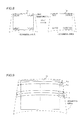
- the scanning loci of the laser beams emitted from the projector 100 are drawn to gradually separate from the projector 100 while horizontally oscillating, as shown in Fig. 4 . Further, the scanning loci of the laser beams are relatively linearly drawn with small lateral widths on a side closer to the projector 100, and relatively linearly drawn with large lateral widths on a side farther from the projector 100. Therefore, a scanning area is trapezoidally shaped with respect to the rectangular image 1a, and hence distortion must be corrected when the projector 100 projects the image 1a.
- the picture processing portion 111 controls the beam source control portion 112 to output the laser beams of the colors corresponding to the pixels of the image 1a along the scanning loci of the laser beams estimated on the basis of the relational expression, described later, between the time information and the image coordinate transformation information, as shown in Fig. 5 .
- the picture processing portion 111 controls the beam source control portion 112 to output the laser beams of the colors corresponding to the respective pixels in order of p1 to p7 through which the estimated scanning loci pass, for example.
- the picture processing portion 111 controls the beam source control portion 112 not to output the laser beams while scanning an area outside the image 1a.
- the picture processing portion 111 controls the beam source control portion 112 to output the laser beams of the colors corresponding to the respective pixels in response to the scanning loci, thereby correcting the distortion of the image 1a.
- the picture processing portion 111 corrects the distortion of the projected image 1a by changing output timing for the laser beams as compared with a case of not correcting the distortion on the same scanning position.
- reflection of the laser beams is described with reference to a coordinate system having the origin at the center of the MEMS mirror 109a shown in Fig. 6 is described. It is assumed that vertical and horizontal driving axes of the MEMS mirror 109a are positioned on x-and y-axes respectively.
- a point P is that on a normal of the MEMS mirror 109a.
- a point Q is that in a direction where the laser beams emitted from the laser beam sources 103 to 105 enter the MEMS mirror 109a.
- a point R is that in a direction where the MEMS mirror 109a scans the laser beams on the table 1.
- a point S is that where the MEMS mirror 109a scans the laser beams on the table 1. It is assumed that the point Q remains on the same position with respect to the center of the HEMS mirror 109a in an unmoved manner.
- the MEMS mirror 109a is driven to scan the laser beams so that the point S moves on the table 1.
- a process of deriving the relational expression between the time information and the image coordinate transformation information is described with reference to expressions (1) to (7).
- the MEMS mirror 109a is vertically driven (on the x-axis) by ⁇ v on an angle ⁇ at a constant rotational speed according to the expression (1), as shown in Fig. 7 . Further, the MEMS mirror 109a is horizontally resonance-driven (on the y-axis) so that the rotation angle is constant, as shown in the expression (2).
- ⁇ v (t) represents the vertical rotation angle (on the x-axis) of the MEMS mirror 109a corresponding to the time t
- ⁇ represents the angle of the center of driving of the MEMS mirror 109a
- ⁇ v represents an amplitude angle
- a represents the rotation speed respectively.
- ⁇ v (t) represents the horizontal rotation angle (on the y-axis) of the MEMS mirror 109a corresponding to the time t
- ⁇ hmax represents an amplitude angle
- ⁇ represents an angular speed
- f represents a frequency corresponding to the angular speed ⁇
- ⁇ represents the circular constant respectively.
- the horizontal amplitude angle of the MEMS mirror 109a is so changed that the value of the amplitude angle ⁇ hmax in the expression (2) is also changed correspondingly.
- the driving frequency is changed, the values of the angular speed ⁇ and the frequency f in the expression (2) are also changed correspondingly.
- ⁇ represents an angle of the point Q from the y-axis.
- x r (t), y r (t) and z r (t) represent x-, y- and z-coordinates of the point R corresponding to the time t respectively.
- a projection surface of the table 1 is positioned on a plane, perpendicular to the z-axis, passing through (0,0,D).
- D represents the z-coordinate of the table 1.
- the picture processing portion 111 and the position acquisition CPU 122 estimate scanning loci of the laser beams on the table 1 on the basis of the derived relational expression (7) between the time information and the image coordinate transformation information.
- the picture processing portion 111 and the position acquisition CPU 122 estimate scanning loci of the laser beams on the table 1 by approximating the scanning loci every line responsive to the horizontal synchronizing signal, as shown in Fig. 9 .
- the position acquisition CPU 122 estimates the scanning loci every line for scanning the laser beams.
- the picture processing portion 111 and the position acquisition CPU 122 estimate the scanning loci of the laser beams on the table 1 as approximations on the basis of the same relational expression between the time information and the image coordinate transformation information.
- the projector 100 is provided with the position acquisition CPU 122 acquiring the position of the touch pen 2 on the basis of the photoreceiving information of the laser beams received by the light detection portion 121 and the information of the projection angle employed by the picture processing portion 111 for correcting the image 1a, the driving frequency for the MEMS mirror 109a, the scanning angle of the MEMS mirror 109a, the resolution of the image 1a and the aspect ratio of the image 1a so that the position acquisition CPU 122 can acquire the position of the touch pen 2 by employing the projection angle common to that employed for correcting the image 1a, the driving frequency for the MEMS mirror 109a, the scanning angle of the MEMS mirror 109a, the resolution of the image 1a and the aspect ratio of the image 1a, whereby the position of the touch pen 2 can be acquired to correspond to the image 1a whose distortion has been corrected. Consequently, the position acquisition CPU 122 can accurately acquire the position of the touch pen 2 corresponding to the image 1a whose distortion has been corrected
- the picture processing portion 111 is formed to estimate the scanning loci of the laser beams on the table 1 on the basis of the information of the projection angle, the driving frequency for the MEMS mirror 109a, the scanning angle of the MEMS mirror 109a, the resolution of the image 1a and the aspect ratio of the image 1a and to correct distortion of the projected image 1a on the basis of the estimated scanning loci while the position acquisition CPU 122 is formed to estimate the scanning loci of the laser beams on the table 1 on the basis of the information of the projection angle, the driving frequency for the MEMS mirror 109a, the scanning angle of the MEMS mirror 109a, the resolution of the image 1a and the aspect ratio of the image 1a and to acquire the position of the touch pen 2 on the basis of the estimated scanning loci and the photoreceiving information so that the position acquisition CPU 122 estimates the scanning loci employed for acquiring the position of the touch pen 2 on the basis of the same information of the projection angle, the driving frequency for the MEMS mirror 109a,
- the picture processing portion 111 is formed to update the information of the projection angle, the driving frequency for the MEMS mirror 109a, the scanning angle of the MEMS mirror 109a, the resolution of the image 1a and the aspect ratio of the image 1a in the blanking period so that the same updates the information of the projection angle, the driving frequency for the MEMS mirror 109a, the scanning angle of the MEMS mirror 109a, the resolution of the image 1a and the aspect ratio of the image 1a in the blanking period when no laser beams are output, whereby the picture processing portion 111 can be inhibited from updating the corrected image 1a while scanning one picture display frame.
- the picture processing portion 111 and the position acquisition CPU 122 are formed to update the information of the projection angle, the driving frequency for the MEMS mirror 109a, the scanning angle of the MEMS mirror 109a, the resolution of the image 1a and the aspect ratio of the image 1a in synchronization with each other so that the projector 100 can update the scanning loci estimated by the picture processing portion 111 on the basis of the information of the projection angle, the driving frequency for the MEMS mirror 109a, the scanning angle of the MEMS mirror 109a, the resolution of the image 1a and the aspect ratio of the image 1a and those estimated by the position acquisition CPU 122 on the basis of the information of the projection angle, the driving frequency for the MEMS mirror 109a, the scanning angle of the MEMS mirror 109a, the resolution of the image 1a and the aspect ratio of the image 1a at substantially identical timing, whereby the position acquisition CPU 122 can accurately acquire the position of the touch pen 2 corresponding to the corrected image 1a also immediately after the picture processing portion 111
- the position acquisition CPU 122 is formed not to acquire the position of the touch pen 2 until the prescribed time (one second, for example) elapses after the updating operation when updating the information of the projection angle, the driving frequency for the MEMS mirror 109a, the scanning angle of the MEMS mirror 109a, the resolution of the image 1a and the aspect ratio of the image 1a, whereby the position acquisition CPU 122 can acquire the position of the touch pen 2 after movement thereof also when the same updates the corrected image 1a by updating the information of the projection angle, the driving frequency for the MEMS mirror 109a, the scanning angle of the MEMS mirror 109a, the resolution of the image 1a and the aspect ratio of the image 1a and the user moves the touch pen 2 correspondingly to the updated corrected image 1a.
- the picture processing portion 111 is formed to estimate the scanning loci of the laser beams on the table 1 on the basis of the same relational expression as that between the time information and the image coordinate transformation information employed by the position acquisition CPU 122 for estimating the scanning loci of the laser beams on the table 1 and to correct distortion of the projected image 1a on the basis of the estimated scanning loci so that the scanning loci estimated by the picture processing portion 111 and the position acquisition CPU 122 respectively are identical to each other, whereby the position acquisition CPU 122 can more accurately acquire the position of the touch pen 2 corresponding to the corrected image 1a.
- the position acquisition CPU 122 is formed to estimate the scanning loci every line for scanning the laser beams thereby estimating the scanning loci every line also when the shapes of lines of the scanning loci of the laser beams on the table 1 vary with the distances from the projector 100, whereby the position acquisition CPU 122 can accurately acquire the position of the touch pen 2.
- the position acquisition CPU 122 is formed to estimate the scanning loci by approximating the relational expression between the time information and the image coordinate transformation information, whereby the same can easily estimate the scanning loci of the laser beams on the table 1 by approximation on the basis of the relational expression between the time information and the image coordinate transformation information.
- the present invention is not restricted to this.
- the image 1a may alternatively be projected on another projection area such as a screen, of may be projected on at least two projection areas such as a table and a screen by separating laser beams.
- the present invention is not restricted to this.
- image correction information and position acquisition information may alternatively simply include at least single identical projection condition information.
- the information of the projection angle, the driving frequency for the MEMS mirror 109a, the scanning angle of the MEMS mirror 109a, the resolution of the image 1a and the aspect ratio of the image 1a may be employed as the image correction information, and only the information of the projection angle may be employed as the position acquisition information.
- the position acquisition portion may not make complicated calculations for estimating the scanning loci, but may be brought into a simple structure.
- the relational expression between the time information and the image coordinate transformation information employed by the image correction portion for estimating the scanning loci of the laser beams and the relational expression between the time information and the image coordinate transformation information employed by the position acquisition portion for estimating the scanning loci of the laser beams may alternatively be different from each other, so far as at least single identical projection condition information is employed.
- the projector 100 acquires the position (coordinates) of the touch pen 2 as a detection object by applying the red, green and blue laser beams projecting the image 1a in the aforementioned embodiment, the present invention is not restricted to this. According to the present invention, the projector 100 may alternatively sense the position (coordinates) of a detection object with a laser beam, such as an infrared laser beam, not contributing to image projection but dedicated to detection (of invisible rays).
- a laser beam such as an infrared laser beam
- the present invention is not restricted to this.
- the photoreceiving portion may alternatively be provided on an apparatus other than the projector, for example.
- the position acquisition portion, the photoreceiving portion and the image correction portion may be provided on apparatuses different from each other.
- the picture processing portion 111 serving as an image correction portion and the position acquisition CPU 122 serving as a position acquisition portion estimate the scanning loci of the laser beams by approximating the scanning loci every line responsive to the horizontal scanning signal in the aforementioned embodiment
- the present invention is not restricted to this.
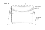
- the image correction portion and the position acquisition portion may alternatively estimate scanning loci of laser beams on a projection area every frame as shown in Fig. 10 on the basis of the derived relational expression (7) between the time information and the image coordinate transformation information, for example.
- the delay time ⁇ t is a constant time (0.1 msec, for example).
- the position of a detection object can be more accurately acquired by taking the delay time ⁇ t into consideration.
- w(t) represents coordinates of the scanning loci of the laser beams on the projection area corresponding to the time t.
Landscapes
- Engineering & Computer Science (AREA)
- Physics & Mathematics (AREA)
- Theoretical Computer Science (AREA)
- General Engineering & Computer Science (AREA)
- Multimedia (AREA)
- General Physics & Mathematics (AREA)
- Signal Processing (AREA)
- Human Computer Interaction (AREA)
- Computer Hardware Design (AREA)
- Optics & Photonics (AREA)
- Geometry (AREA)
- Transforming Electric Information Into Light Information (AREA)
- Mechanical Optical Scanning Systems (AREA)
Abstract
Description
- The present invention relates to a projector including a laser beam generation portion.
- A projector including a laser beam generation portion is known in general, as disclosed in Japanese Patent Laying-Open No.
2010-243808 - The aforementioned Japanese Patent Laying-Open No.
2010-243808 - A technique of correcting distortion of a projected image by changing the output timing for a laser beam is also known in general.
- In a case of correcting the distortion of the projected image by changing the output timing for the laser beam in the projector described in the aforementioned Japanese Patent Laying-Open No.
2010-243808 - The present invention has been proposed in order to solve the aforementioned problems, and an object of the present invention is to provide a projector capable of accurately acquiring the position of a detection object corresponding to an image whose distortion has been corrected when projecting the image while correcting the distortion.
- A projector according to an aspect of the present invention includes a laser beam generation portion outputting a laser beam, an image projection portion, including a scanning portion scanning the laser beam, projecting an image on a projection area, an image correction portion correcting distortion of the projected image on the basis of projection condition information, a photoreceiving portion receiving the laser beam reflected by a detection object, and a position acquisition portion acquiring the position of the detection object on the basis of photoreceiving information of the laser beam received by the photoreceiving portion and the projection condition information employed by the image correction portion for correcting the image.
- As hereinabove described, the projector according to the aspect is provided with the position acquisition portion acquiring the position of the detection object on the basis of the photoreceiving information of the laser beam received by the photoreceiving portion and the projection condition information employed by the image correction portion for correcting the image so that the position acquisition portion can acquire the position of the detection object by employing the projection condition information common to that employed for correcting the image, whereby the position of the detection object can be acquired to correspond to the image whose distortion has been corrected. Consequently, the position of the detection object corresponding to the image whose distortion has been corrected can be accurately acquired when the projector projects the image while correcting the distortion.
- In the aforementioned projector according to the aspect, the image correction portion is preferably formed to estimate a scanning locus of the laser beam on the projection area on the basis of image correction information including the projection condition information and to correct the distortion of the projected image on the basis of the estimated scanning locus, and the position acquisition portion is preferably formed to estimate a scanning locus of the laser beam on the projection area on the basis of position acquisition information including the projection condition information and to acquire the position of the detection object on the basis of the estimated scanning locus and the photoreceiving information. According to this structure, the position acquisition portion estimates the scanning locus employed for acquiring the position of the detection object on the basis of the same projection condition information as that for the scanning locus employed by the image correction portion for correcting the image, whereby the position acquisition portion can easily accurately acquire the position of the detection object corresponding to the corrected image.
- In this case, the projector is preferably so formed as to update the image correction information and the position acquisition information in synchronization with a cycle of natural number times a picture display frame cycle. According to this structure, the image correction information and the position acquisition information are not updated in excess of twice in one picture display frame, whereby the position acquisition portion can accurately acquire the position of the detection object corresponding to the corrected image without a complicated position acquisition control operation.
- The aforementioned projector having such a structure that the image correction portion estimates the scanning locus of the laser beam on the projection area on the basis of the image correction information is preferably so formed as to update the image correction information and the position acquisition information in a blanking period. According to this structure, the projector updates the image correction information and the position acquisition information in the blanking period when no laser beam is output, whereby the projector can be inhibited from updating the corrected image while scanning one picture display frame, for example.
- The aforementioned projector having such a structure that the image correction portion estimates the scanning locus of the laser beam on the projection area on the basis of the image correction information is preferably so formed as to update the image correction information and the position acquisition information in synchronization with each other. According to this structure, the projector can update the scanning locus estimated by the image correction portion on the basis of the image correction information and the scanning locus estimated by the position acquisition portion on the basis of the position acquisition information at identical timing, whereby the position acquisition portion can accurately acquire the position of the detection object corresponding to the corrected image also immediately after the image correction portion corrects the image correspondingly to the updated image correction information.
- In the aforementioned projector having such a structure that the image correction portion estimates the scanning locus of the laser beam on the projection area on the basis of the image correction information, the projection condition information preferably includes at least one of a projection angle, a driving frequency for the scanning portion, a scanning angle of the scanning portion, resolution of the image and an aspect ratio of the image. According to this structure, the position of the detection object corresponding to the image whose distortion has been corrected can be easily accurately acquired by employing at least one of the projection angle, the driving frequency for the scanning portion, the scanning angle of the scanning portion, the resolution of the image and the aspect ratio of the image in common to the correction of the distortion of the image and the acquisition of the position of the detection object.
- In the aforementioned projector having such a structure that the image correction portion estimates the scanning locus of the laser beam on the projection area on the basis of the image correction information, the position acquisition portion is preferably formed not to acquire the position of the detection object until a prescribed time elapses after the updating when the position acquisition information is updated. According to this structure, the position acquisition portion can acquire the position of the detection object after movement thereof also when the projector updates the corrected image by updating the image correction information along with the position acquisition information and the user moves the detection object correspondingly to the updated corrected image.
- In the aforementioned projector having such a structure that the image correction portion estimates the scanning locus of the laser beam on the projection area on the basis of the image correction information, the position acquisition portion is preferably formed to estimate a scanning locus of the laser beam on the projection area on the basis of a relational expression between time information and image coordinate transformation information derived by employing the position acquisition information and to acquire the position of the detection object corresponding to the corrected image projected in a state where the distortion of the image has been corrected on the basis of the estimated scanning locus and the photoreceiving information. According to this structure, the position acquisition portion can easily estimate the scanning locus of the laser beam on the projection area on the basis of the relational expression between the time information and the image coordinate transformation information derived by employing the position acquisition information.
- In this case, the image correction portion is preferably formed to estimate a scanning locus of the laser beam on the projection area on the basis of a relational expression between time information and image coordinate transformation information derived by employing the image correction information identical to the position acquisition information and to correct the distortion of the projected image on the basis of the estimated scanning locus. According to this structure, the image correction portion and the position acquisition portion estimate the scanning loci on the basis of the relational expression between the time information and the image coordinate transformation information derived by employing the same information, whereby the position acquisition portion can more accurately acquire the position of the detection object corresponding to the corrected image.
- In the aforementioned projector having such a structure that the position acquisition portion estimates the scanning locus of the laser beam on the projection area on the basis of the relational expression between the time information and the image coordinate transformation information, the image correction portion is preferably formed to estimate a scanning locus of the laser beam on the projection area on the basis of the same relational expression as the relational expression between the time information and the image coordinate transformation information employed by the position acquisition portion for estimating the scanning locus of the laser beam on the projection area and to correct the distortion of the projected image on the basis of the estimated scanning locus. According to this structure, the scanning loci estimated by the image correction portion and the position acquisition portion respectively are identical to each other, whereby the position acquisition portion can more accurately acquire the position of the detection object corresponding to the corrected image.
- In the aforementioned projector having such a structure that the image correction portion estimates the scanning locus of the laser beam on the projection area on the basis of the image correction information, the position acquisition portion is preferably formed to estimate the scanning locus every line for scanning the laser beam. According to this structure, the position acquisition portion estimates the scanning locus every line also when the shape of the line of the scanning locus of the laser beam on the projection area varies with the distance from the projector, whereby the same can accurately acquire the position of the detection object.
- In the aforementioned projector having such a structure that the image correction portion estimates the scanning locus of the laser beam on the projection area on the basis of the image correction information, the position acquisition portion is preferably formed to estimate the scanning locus every frame. According to this structure, the position acquisition portion can collectively estimate the scanning locus at a time every frame.
- In the aforementioned projector having such a structure that the position acquisition portion estimates the scanning locus of the laser beam on the projection area on the basis of the relational expression between the time information and the image coordinate transformation information, the position acquisition portion is preferably formed to estimate the scanning locus by approximating the relational expression between the time information and the image coordinate transformation information. According to this structure, the position acquisition portion can easily estimate the scanning locus of the laser beam on the projection area by approximating the relational expression between the time information and the image coordinate transformation information.
- In the aforementioned projector having such a structure that the position acquisition portion estimates the scanning locus of the laser beam on the projection area on the basis of the relational expression between the time information and the image coordinate transformation information, the position acquisition portion is preferably formed to derive the relational expression between the time information and the image coordinate transformation information in consideration of a delay time in circuit processing. According to this structure, the position acquisition portion can more accurately acquire the position of the detection object by taking the delay time in circuit processing into consideration.
- In the aforementioned projector according to the aspect, the position acquisition portion may be constituted of a control portion.
- The foregoing and other objects, features, aspects and advantages of the present invention will become more apparent from the following detailed description of the present invention when taken in conjunction with the accompanying drawings.
-
-
Fig. 1 is a schematic diagram showing a used state of a projector according to an embodiment of the present invention; -
Fig. 2 is a block diagram showing the structure of the projector according to the embodiment of the present invention; -
Fig. 3 is a diagram for illustrating reflected laser beams received by the projector according to the embodiment of the present invention; -
Fig. 4 is a diagram for illustrating a scanning area of the projector according to the embodiment of the present invention; -
Fig. 5 is a diagram for illustrating image correction in the projector according to the embodiment of the present invention; -
Fig. 6 is a diagram for illustrating reflection of laser beams in the projector according to the embodiment of the present invention; -
Fig. 7 is a diagram for illustrating vertical driving of an MEMS mirror of the projector according to the embodiment of the present invention; -
Fig. 8 is a diagram for illustrating image coordinate transformation in the projector according to the embodiment of the present invention; -
Fig. 9 is a diagram for illustrating approximations of scanning loci in the projector according to the embodiment of the present invention; and -
Fig. 10 is a diagram for illustrating scanning loci in a modification of the projector according to the embodiment of the present invention. - An embodiment of the present invention is now described with reference to the drawings.
- The structure of a
projector 100 according to the embodiment of the present invention is described with reference toFigs. 1 to 3 . - The
projector 100 according to the embodiment of the present invention is formed to be used in a state arranged on a table 1, as shown inFig. 1 . Further, theprojector 100 is formed to project animage 1a on the upper surface of a projection area such as the table 1. The table 1 is an example of the "projection area" in the present invention. - The
projector 100 includes amain CPU 101, anoperation portion 102, threelaser beam sources 103 to 105, two polarizingbeam splitters image projection portion 109, adisplay control portion 110 and a pointingdetection control portion 120, as shown inFig. 2 . Theimage projection portion 109 includes an MEMS (Micro Electro Mechanical System)mirror 109a. Thedisplay control portion 110 includes a picture processing portion 111, a beamsource control portion 112, an LD (laser diode)driver 113, amirror control portion 114 and amirror driver 115. The pointingdetection control portion 120 includes alight detection portion 121 and aposition acquisition CPU 122. Thelaser beam sources 103 to 105 are examples of the "laser beam generation portion" in the present invention, and theMEMS mirror 109a is an example of the "scanning portion" in the present invention. The picture processing portion 111 is an example of the "image correction portion" in the present invention. Thelight detection portion 121 is an example of the "photoreceiving portion" in the present invention, and theposition acquisition CPU 122 is an example of the "position acquisition portion" or the "control portion" in the present invention. - The
main CPU 101 is formed to control the respective portions of theprojector 100. Theoperation portion 102 is provided for accepting an operation of supplying power to theprojector 100, an operation of changing a projection angle for theimage 1a and an operation of changing the resolution of theimage 1a. Thelaser beam source 103 is formed to apply a blue laser beam to theMEMS mirror 109a through thepolarizing beam splitter 106 and thelens 108. Thelaser beam sources MEMS mirror 109a through thepolarizing beam splitters lens 108 respectively. - The
image projection portion 109 is formed to project theimage 1a (seeFig. 1 ) on the table 1. More specifically, theMEMS mirror 109a of theimage projection portion 109 is formed to project theimage 1a on the table 1 by scanning the laser beams emitted from thelaser beam sources 103 to 105. TheMEMS mirror 109a is formed to scan the laser beams by driving the same on two axes in the horizontal and vertical directions. Further, theMEMS mirror 109a is formed to scan the horizontal direction at a high speed by resonance driving and to scan the vertical direction at a low speed by DC driving. - The picture processing portion 111 is formed to control projection of a picture on the basis of an externally input picture signal. More specifically, the picture processing portion 111 is formed to control driving of the
MEMS mirror 109a through themirror control portion 114 and to control application of the laser beams by thelaser beam sources 103 to 105 through the beamsource control portion 112 on the basis of the externally input picture signal. Further, the picture processing portion 111 is formed to correct distortion of the projectedimage 1a. - More specifically, the picture processing portion 111 derives a relational expression (see an expression (7) described below), described later, between time information and image coordinate transformation information on the basis of a projection angle, a driving frequency for the
MEMS mirror 109a, a scanning angle of theMEMS mirror 109a, resolution of theimage 1a and an aspect ratio of theimage 1a. Further, the picture processing portion 111 is formed to estimate scanning loci of the laser beams on the table 1 on the basis of the derived relational expression between the time information and the image coordinate transformation information and to correct distortion of theimage 1a on the basis of the estimated scanning loci. In addition, the picture processing portion 111 is formed to update information of the projection angle, the driving frequency for theMEMS mirror 109a, the scanning angle of theMEMS mirror 109a, the resolution of theimage 1a and the aspect ratio of theimage 1a in a blanking period between frames in a cycle of natural number times a frame cycle. Further, the picture processing portion 111 is formed to update the information of the projection angle and the information of the scanning angle of theMEMS mirror 109a when the user changes the projection angle. Further, the picture processing portion 111 is formed to update the information of the resolution of theimage 1a and the information of the aspect ratio of theimage 1a respectively when the user changes the resolution and the aspect ratio. Further, the picture processing portion 111 is formed to update the information of the driving frequency when the resonance frequency of theMEMS mirror 109a fluctuates due to temperature fluctuation or the like. Further, the picture processing portion 111 is formed to be capable of transmitting a synchronizing signal for controlling theposition acquisition CPU 122 to update the information of the projection angle, the driving frequency for theMEMS mirror 109a, the scanning angle of theMEMS mirror 109a, the resolution of theimage 1a and the aspect ratio of theimage 1a. The information of the projection angle, the driving frequency for theMEMS mirror 109a, the scanning angle of theMEMS mirror 109a, the resolution of theimage 1a and the aspect ratio of theimage 1a is an example of the "projection condition information" or the "image correction information" in the present invention. - The beam
source control portion 112 is formed to control theLD driver 113 thereby controlling the emission of the laser beams by thelaser beam sources 103 to 105 on the basis of control by the picture processing portion 111. More specifically, the beamsource control portion 112 is formed to control thelaser beam sources 103 to 105 to emit the laser beams of colors corresponding to respective pixels of theimage 1a in synchronization with scanning timing of theMEMS mirror 109a. - The
mirror control portion 114 is formed to control themirror driver 115 thereby controlling driving of theMEMS mirror 109a on the basis of control by the picture processing portion 111. - According to this embodiment, the
light detection portion 121 is formed to receive (detect) the laser beams reflected by a touch pen 2, as shown inFig. 3 . Theposition acquisition CPU 122 is formed to acquire the position of the touch pen 2 on the basis of time information about the time when thelight detection portion 121 has detected the reflected laser beams and the scanning loci of the laser beams. More specifically, theposition acquisition CPU 122 acquires the position of the touch pen 2 corresponding to theimage 1a by specifying on which positions the detected laser beams are scanned with respect to theimage 1a on the basis of an elapsed time up to detection of the laser beams from the horizontal synchronizing signal and the scanning loci of the laser beams. Further, theposition acquisition CPU 122 derives the relational expression (see the expression (7) described below), described later, between the time information and the image coordinate transformation information on the basis of the information of the projection angle, the driving frequency for theMEMS mirror 109a, the scanning angle of theMEMS mirror 109a, the resolution of theimage 1a and the aspect ratio of theimage 1a. Theposition acquisition CPU 122 is formed to specify the scanning loci of the laser beams on the basis of the derived relational expression between the time information and the image coordinate transformation information. More specifically, theposition acquisition CPU 122 is formed to estimate the scanning loci of the laser beams by approximating the relational expression between the time information and the image coordinate transformation information. The information of the projection angle, the driving frequency for theMEMS mirror 109a, the scanning angle of theMEMS mirror 109a, the resolution of theimage 1a and the aspect ratio of theimage 1a is an example of the "position acquisition information" in the present invention. The time information is an example of the "photoreceiving information" in the present invention. - The
position acquisition CPU 122 is formed to update the information of the projection angle, the driving frequency for theMEMS mirror 109a, the scanning angle of theMEMS mirror 109, the resolution of theimage 1a and the aspect ratio of theimage 1a when receiving the synchronizing signal from the picture processing portion 111. Further, theposition acquisition CPU 122 is formed not to perform position acquisition until a prescribed time (one second, for example) elapses after the updating operation when updating the information of the projection angle, the driving frequency for theMEMS mirror 109a, the scanning angle of theMEMS mirror 109, the resolution of theimage 1a and the aspect ratio of theimage 1a. - Correction of distortion of the
image 1a in theprojector 100 according to the embodiment of the present invention is described with reference toFigs. 4 and5 . - The scanning loci of the laser beams emitted from the
projector 100 are drawn to gradually separate from theprojector 100 while horizontally oscillating, as shown inFig. 4 . Further, the scanning loci of the laser beams are relatively linearly drawn with small lateral widths on a side closer to theprojector 100, and relatively linearly drawn with large lateral widths on a side farther from theprojector 100. Therefore, a scanning area is trapezoidally shaped with respect to therectangular image 1a, and hence distortion must be corrected when theprojector 100 projects theimage 1a. - The picture processing portion 111 controls the beam
source control portion 112 to output the laser beams of the colors corresponding to the pixels of theimage 1a along the scanning loci of the laser beams estimated on the basis of the relational expression, described later, between the time information and the image coordinate transformation information, as shown inFig. 5 . In this case, the picture processing portion 111 controls the beamsource control portion 112 to output the laser beams of the colors corresponding to the respective pixels in order of p1 to p7 through which the estimated scanning loci pass, for example. Further, the picture processing portion 111 controls the beamsource control portion 112 not to output the laser beams while scanning an area outside theimage 1a. Thus, the picture processing portion 111 controls the beamsource control portion 112 to output the laser beams of the colors corresponding to the respective pixels in response to the scanning loci, thereby correcting the distortion of theimage 1a. In other words, the picture processing portion 111 corrects the distortion of the projectedimage 1a by changing output timing for the laser beams as compared with a case of not correcting the distortion on the same scanning position. - Operations of the picture processing portion 111 and the
position acquisition CPU 122 of theprojector 100 according to the embodiment of the present invention estimating scanning loci of the laser beams on the table 1 are described with reference toFigs. 6 to 9 . - First, reflection of the laser beams is described with reference to a coordinate system having the origin at the center of the
MEMS mirror 109a shown inFig. 6 is described. It is assumed that vertical and horizontal driving axes of theMEMS mirror 109a are positioned on x-and y-axes respectively. A point P is that on a normal of theMEMS mirror 109a. A point Q is that in a direction where the laser beams emitted from thelaser beam sources 103 to 105 enter theMEMS mirror 109a. A point R is that in a direction where theMEMS mirror 109a scans the laser beams on the table 1. A point S is that where theMEMS mirror 109a scans the laser beams on the table 1. It is assumed that the point Q remains on the same position with respect to the center of theHEMS mirror 109a in an unmoved manner. TheMEMS mirror 109a is driven to scan the laser beams so that the point S moves on the table 1. - A process of deriving the relational expression between the time information and the image coordinate transformation information is described with reference to expressions (1) to (7). A start time of each frame is set as t = 0. The
MEMS mirror 109a is vertically driven (on the x-axis) by ±θv on an angle α at a constant rotational speed according to the expression (1), as shown inFig. 7 . Further, theMEMS mirror 109a is horizontally resonance-driven (on the y-axis) so that the rotation angle is constant, as shown in the expression (2). Referring to the expression (1), θv(t) represents the vertical rotation angle (on the x-axis) of theMEMS mirror 109a corresponding to the time t, α represents the angle of the center of driving of theMEMS mirror 109a, θv represents an amplitude angle, and a represents the rotation speed respectively. Referring to the expression (2), θv(t) represents the horizontal rotation angle (on the y-axis) of theMEMS mirror 109a corresponding to the time t, θhmax represents an amplitude angle, ω represents an angular speed, f represents a frequency corresponding to the angular speed ω, and π represents the circular constant respectively.
- When a frame rate is changed, the vertical rotation speed of the
MEMS mirror 109a is so changed that the value of the rotation speed a in the expression (1) is also changed correspondingly. When the projection angle is changed, the center of vertical driving of theMEMS mirror 109a is so changed that the value of the angle α in the expression (1) is also changed correspondingly.
- When the aspect ratio or the scanning angle is changed, the horizontal amplitude angle of the
MEMS mirror 109a is so changed that the value of the amplitude angle θhmax in the expression (2) is also changed correspondingly. When the driving frequency is changed, the values of the angular speed ω and the frequency f in the expression (2) are also changed correspondingly. - The position vector of the point Q is expressed as follows:

- Referring to the expression (3), β represents an angle of the point Q from the y-axis.
- The unit vector of the
MEMS mirror 109a in the normal direction is expressed as follows:
- Hence, the vector of the point R in the scanned direction is expressed as follows:

- Referring to the expression (5), xr(t), yr(t) and zr(t) represent x-, y- and z-coordinates of the point R corresponding to the time t respectively.
- A projection surface of the table 1 is positioned on a plane, perpendicular to the z-axis, passing through (0,0,D). Hence, the point S scanned on the table 1 is expressed as follows:

- Referring to the expression (6), D represents the z-coordinate of the table 1.
- When linearly transforming the x- and y-coordinates of the point S with v(x,y) to correspond to pixels of the
image 1a as shown inFig. 8 , the relational expression between the time information and the image coordinate transformation information is expressed as follows:
- The picture processing portion 111 and the
position acquisition CPU 122 estimate scanning loci of the laser beams on the table 1 on the basis of the derived relational expression (7) between the time information and the image coordinate transformation information. - According to this embodiment, the picture processing portion 111 and the
position acquisition CPU 122 estimate scanning loci of the laser beams on the table 1 by approximating the scanning loci every line responsive to the horizontal synchronizing signal, as shown inFig. 9 . In other words, theposition acquisition CPU 122 estimates the scanning loci every line for scanning the laser beams. Further, the picture processing portion 111 and theposition acquisition CPU 122 estimate the scanning loci of the laser beams on the table 1 as approximations on the basis of the same relational expression between the time information and the image coordinate transformation information. - Approximations on an i-th line are described with reference to the expressions (8) and (9). Expressions of u(t) are Taylor-expanded and approximated assuming that tofs represents a time with reference to the horizontal synchronizing signal. A time on a start position of the i-th line is set as tofs = 0. A time on an end position of the i-th line can be expressed as tofs = 1/2f with the horizontal frequency f of the
MEMS mirror 109a. When the expressions are Taylor-expanded with reference to a time tofs = 1/4f between the start position and the end position, x- and y-coordinates are expressed as follows:

- Referring to the expression (8), uix(tofs) represents the x-coordinates of the scanning loci of the laser beams on the table 1 corresponding to the time tofs. Further, a0ix to a7ix represent differential coefficients of zero- to seventh-order differentials of functions of the x-coordinates of u(t) at t = 1/4f (expansion center) respectively. Referring to the expression (9), uiy(tofs) represents the y-coordinates of the scanning loci of the laser beams on the table 1 corresponding to the time tofs. Further, a0iy to a7iy represent differential coefficients of zero- to seventh-order differentials of functions of the x-coordinates of u(t) at t = 1/4f (expansion center) respectively.
- According to this embodiment, as hereinabove described, the
projector 100 is provided with theposition acquisition CPU 122 acquiring the position of the touch pen 2 on the basis of the photoreceiving information of the laser beams received by thelight detection portion 121 and the information of the projection angle employed by the picture processing portion 111 for correcting theimage 1a, the driving frequency for theMEMS mirror 109a, the scanning angle of theMEMS mirror 109a, the resolution of theimage 1a and the aspect ratio of theimage 1a so that theposition acquisition CPU 122 can acquire the position of the touch pen 2 by employing the projection angle common to that employed for correcting theimage 1a, the driving frequency for theMEMS mirror 109a, the scanning angle of theMEMS mirror 109a, the resolution of theimage 1a and the aspect ratio of theimage 1a, whereby the position of the touch pen 2 can be acquired to correspond to theimage 1a whose distortion has been corrected. Consequently, theposition acquisition CPU 122 can accurately acquire the position of the touch pen 2 corresponding to theimage 1a whose distortion has been corrected when theprojector 100 projects theimage 1a while correcting the distortion thereof. - According to this embodiment, as hereinabove described, the picture processing portion 111 is formed to estimate the scanning loci of the laser beams on the table 1 on the basis of the information of the projection angle, the driving frequency for the MEMS mirror 109a, the scanning angle of the MEMS mirror 109a, the resolution of the image 1a and the aspect ratio of the image 1a and to correct distortion of the projected image 1a on the basis of the estimated scanning loci while the position acquisition CPU 122 is formed to estimate the scanning loci of the laser beams on the table 1 on the basis of the information of the projection angle, the driving frequency for the MEMS mirror 109a, the scanning angle of the MEMS mirror 109a, the resolution of the image 1a and the aspect ratio of the image 1a and to acquire the position of the touch pen 2 on the basis of the estimated scanning loci and the photoreceiving information so that the position acquisition CPU 122 estimates the scanning loci employed for acquiring the position of the touch pen 2 on the basis of the same information of the projection angle, the driving frequency for the MEMS mirror 109a, the scanning angle of the MEMS mirror 109a, the resolution of the image 1a and the aspect ratio of the image 1a employed by the picture processing portion 111 for correcting the image 1a, whereby the position acquisition CPU 122 can easily accurately acquire the position of the touch pen 2 corresponding to the corrected image 1a.
- According to this embodiment, as hereinabove described, the picture processing portion 111 is formed to update the information of the projection angle, the driving frequency for the
MEMS mirror 109a, the scanning angle of theMEMS mirror 109a, the resolution of theimage 1a and the aspect ratio of theimage 1a in the blanking period so that the same updates the information of the projection angle, the driving frequency for theMEMS mirror 109a, the scanning angle of theMEMS mirror 109a, the resolution of theimage 1a and the aspect ratio of theimage 1a in the blanking period when no laser beams are output, whereby the picture processing portion 111 can be inhibited from updating the correctedimage 1a while scanning one picture display frame. - According to this embodiment, as hereinabove described, the picture processing portion 111 and the position acquisition CPU 122 are formed to update the information of the projection angle, the driving frequency for the MEMS mirror 109a, the scanning angle of the MEMS mirror 109a, the resolution of the image 1a and the aspect ratio of the image 1a in synchronization with each other so that the projector 100 can update the scanning loci estimated by the picture processing portion 111 on the basis of the information of the projection angle, the driving frequency for the MEMS mirror 109a, the scanning angle of the MEMS mirror 109a, the resolution of the image 1a and the aspect ratio of the image 1a and those estimated by the position acquisition CPU 122 on the basis of the information of the projection angle, the driving frequency for the MEMS mirror 109a, the scanning angle of the MEMS mirror 109a, the resolution of the image 1a and the aspect ratio of the image 1a at substantially identical timing, whereby the position acquisition CPU 122 can accurately acquire the position of the touch pen 2 corresponding to the corrected image 1a also immediately after the picture processing portion 111 corrects the image 1a correspondingly to the updated information of the projection angle, the driving frequency for the MEMS mirror 109a, the scanning angle of the MEMS mirror 109a, the resolution of the image 1a and the aspect ratio of the image 1a.
- According to this embodiment, as hereinabove described, the
position acquisition CPU 122 is formed not to acquire the position of the touch pen 2 until the prescribed time (one second, for example) elapses after the updating operation when updating the information of the projection angle, the driving frequency for theMEMS mirror 109a, the scanning angle of theMEMS mirror 109a, the resolution of theimage 1a and the aspect ratio of theimage 1a, whereby theposition acquisition CPU 122 can acquire the position of the touch pen 2 after movement thereof also when the same updates the correctedimage 1a by updating the information of the projection angle, the driving frequency for theMEMS mirror 109a, the scanning angle of theMEMS mirror 109a, the resolution of theimage 1a and the aspect ratio of theimage 1a and the user moves the touch pen 2 correspondingly to the updated correctedimage 1a. - According to this embodiment, as hereinabove described, the picture processing portion 111 is formed to estimate the scanning loci of the laser beams on the table 1 on the basis of the same relational expression as that between the time information and the image coordinate transformation information employed by the
position acquisition CPU 122 for estimating the scanning loci of the laser beams on the table 1 and to correct distortion of the projectedimage 1a on the basis of the estimated scanning loci so that the scanning loci estimated by the picture processing portion 111 and theposition acquisition CPU 122 respectively are identical to each other, whereby theposition acquisition CPU 122 can more accurately acquire the position of the touch pen 2 corresponding to the correctedimage 1a. - According to this embodiment, as hereinabove described, the
position acquisition CPU 122 is formed to estimate the scanning loci every line for scanning the laser beams thereby estimating the scanning loci every line also when the shapes of lines of the scanning loci of the laser beams on the table 1 vary with the distances from theprojector 100, whereby theposition acquisition CPU 122 can accurately acquire the position of the touch pen 2. - According to this embodiment, as hereinabove described, the
position acquisition CPU 122 is formed to estimate the scanning loci by approximating the relational expression between the time information and the image coordinate transformation information, whereby the same can easily estimate the scanning loci of the laser beams on the table 1 by approximation on the basis of the relational expression between the time information and the image coordinate transformation information. - Although the present invention has been described and illustrated in detail, it is clearly understood that the same is by way of illustration and example only and is not to be taken by way of limitation, the spirit and scope of the present invention being limited only by the terms of the appended claims.
- For example, while the
image 1a is projected on the table 1 as a projection area in the aforementioned embodiment, the present invention is not restricted to this. According to the present invention, theimage 1a may alternatively be projected on another projection area such as a screen, of may be projected on at least two projection areas such as a table and a screen by separating laser beams. - While the information of the projection angle, the driving frequency for the
MEMS mirror 109a, the scanning angle of theMEMS mirror 109a, the resolution of theimage 1a and the aspect ratio of theimage 1a as image correction information and projection condition information employed by the picture processing portion 111 serving as an image correction portion for estimating the scanning loci of the laser beams and the information of the projection angle, the driving frequency for theMEMS mirror 109a, the scanning angle of theMEMS mirror 109a, the resolution of theimage 1a and the aspect ratio of theimage 1a as image correction information and projection condition information employed by theposition acquisition CPU 122 serving as a position acquisition portion for estimating the scanning loci of the laser beams are identical to each other in the aforementioned embodiment, the present invention is not restricted to this. According to the present invention, image correction information and position acquisition information may alternatively simply include at least single identical projection condition information. For example, the information of the projection angle, the driving frequency for theMEMS mirror 109a, the scanning angle of theMEMS mirror 109a, the resolution of theimage 1a and the aspect ratio of theimage 1a may be employed as the image correction information, and only the information of the projection angle may be employed as the position acquisition information. In this case, the position acquisition portion may not make complicated calculations for estimating the scanning loci, but may be brought into a simple structure. - While the relational expression between the time information and the image coordinate transformation information employed by the picture processing portion 111 serving as an image correction portion for estimating the scanning loci of the laser beams and the relational expression between the time information and the image coordinate transformation information employed by the
position acquisition CPU 122 serving as a position acquisition portion for estimating the scanning loci of the laser beams are identical to each other in the aforementioned embodiment, the present invention is not restricted to this. According to the present invention, the relational expression between the time information and the image coordinate transformation information employed by the image correction portion for estimating the scanning loci of the laser beams and the relational expression between the time information and the image coordinate transformation information employed by the position acquisition portion for estimating the scanning loci of the laser beams may alternatively be different from each other, so far as at least single identical projection condition information is employed. - While the
projector 100 acquires the position (coordinates) of the touch pen 2 as a detection object by applying the red, green and blue laser beams projecting theimage 1a in the aforementioned embodiment, the present invention is not restricted to this. According to the present invention, theprojector 100 may alternatively sense the position (coordinates) of a detection object with a laser beam, such as an infrared laser beam, not contributing to image projection but dedicated to detection (of invisible rays). - While the
projector 100 is provided with the picture processing portion 111 serving as an image correction portion, thelight detection portion 121 serving as a photoreceiving portion and theposition acquisition CPU 122 serving as a position acquisition portion in the aforementioned embodiment, the present invention is not restricted to this. According to the present invention, the photoreceiving portion may alternatively be provided on an apparatus other than the projector, for example. Further, the position acquisition portion, the photoreceiving portion and the image correction portion may be provided on apparatuses different from each other. - While the picture processing portion 111 serving as an image correction portion and the
position acquisition CPU 122 serving as a position acquisition portion estimate the scanning loci of the laser beams by approximating the scanning loci every line responsive to the horizontal scanning signal in the aforementioned embodiment, the present invention is not restricted to this. According to the present invention, the image correction portion and the position acquisition portion may alternatively estimate scanning loci of laser beams on a projection area every frame as shown inFig. 10 on the basis of the derived relational expression (7) between the time information and the image coordinate transformation information, for example. In this case, the image correction portion and the position acquisition portion may estimate the scanning loci of the laser beams on the projection area according to the following expression (10), assuming that t = 0 represents a start time of each frame responsively to a vertical synchronizing signal, t represents an elapsed time up to detection of the laser beams from the vertical synchronizing signal and Δt represents a delay time of circuit processing. The delay time Δt is a constant time (0.1 msec, for example). The position of a detection object can be more accurately acquired by taking the delay time Δt into consideration. Referring to the expression (10), w(t) represents coordinates of the scanning loci of the laser beams on the projection area corresponding to the time t.
Claims (15)
- A projector (100) comprising:a laser beam generation portion (103, 104, 105) outputting a laser beam;an image projection portion (109), including a scanning portion (109a) scanning said laser beam, projecting an image (1a) on a projection area (1);an image correction portion (111) correcting distortion of projected said image on the basis of projection condition information;a photoreceiving portion (121) receiving said laser beam reflected by a detection object (2); anda position acquisition portion (122) acquiring the position of said detection object on the basis of photoreceiving information of said laser beam received by said photoreceiving portion and said projection condition information employed by said image correction portion for correcting said image.
- The projector according to claim 1, wherein
said image correction portion is formed to estimate a scanning locus of said laser beam on said projection area on the basis of image correction information including said projection condition information and to correct said distortion of said projected image on the basis of estimated said scanning locus, and
said position acquisition portion is formed to estimate a scanning locus of said laser beam on said projection area on the basis of position acquisition information including said projection condition information and to acquire the position of said detection object on the basis of estimated said scanning locus and said photoreceiving information. - The projector according to claim 2, so formed as to update said image correction information and said position acquisition information in synchronization with a cycle of natural number times a picture display frame cycle.
- The projector according to claim 2, so formed as to update said image correction information and said position acquisition information in a blanking period.
- The projector according to claim 2, so formed as to update said image correction information and said position acquisition information in synchronization with each other.
- The projector according to claim 2, wherein
said projection condition information includes at least one of a projection angle, a driving frequency for said scanning portion, a scanning angle of said scanning portion, resolution of said image and an aspect ratio of said image. - The projector according to claim 2, wherein
said position acquisition portion is formed not to acquire the position of said detection object until a prescribed time elapses after the updating when said position acquisition information is updated. - The projector according to claim 2, wherein
said position acquisition portion is formed to estimate a scanning locus of said laser beam on said projection area on the basis of a relational expression between time information and image coordinate transformation information derived by employing said position acquisition information and to acquire the position of said detection object corresponding to corrected said image projected in a state where said distortion of said image has been corrected on the basis of estimated said scanning locus and said photoreceiving information. - The projector according to claim 8, wherein
said image correction portion is formed to estimate a scanning locus of said laser beam on said projection area on the basis of a relational expression between time information and image coordinate transformation information derived by employing said image correction information identical to said position acquisition information and to correct said distortion of said projected image on the basis of estimated said scanning locus. - The projector according to claim 8, wherein
said image correction portion is formed to estimate a scanning locus of said laser beam on said projection area on the basis of the same relational expression as said relational expression between said time information and said image coordinate transformation information employed by said position acquisition portion for estimating said scanning locus of said laser beam on said projection area and to correct said distortion of said projected image on the basis of estimated said scanning locus. - The projector according to claim 2, wherein
said position acquisition portion is formed to estimate said scanning locus every line for scanning said laser beam. - The projector according to claim 2, wherein
said position acquisition portion is formed to estimate said scanning locus every frame. - The projector according to claim 8, wherein
said position acquisition portion is formed to estimate said scanning locus by approximating said relational expression between said time information and said image coordinate transformation information. - The projector according to claim 8, wherein
said position acquisition portion is formed to derive said relational expression between said time information and said image coordinate transformation information in consideration of a delay time in circuit processing. - The projector according to claim 1, wherein
said position acquisition portion is constituted of a control portion.
Applications Claiming Priority (1)
| Application Number | Priority Date | Filing Date | Title |
|---|---|---|---|
| JP2011201841A JP5864177B2 (en) | 2011-09-15 | 2011-09-15 | Projector and projector system |
Publications (2)
| Publication Number | Publication Date |
|---|---|
| EP2574058A2 true EP2574058A2 (en) | 2013-03-27 |
| EP2574058A3 EP2574058A3 (en) | 2013-05-29 |
Family
ID=47115264
Family Applications (1)
| Application Number | Title | Priority Date | Filing Date |
|---|---|---|---|
| EP12183524.3A Withdrawn EP2574058A3 (en) | 2011-09-15 | 2012-09-07 | Projector |
Country Status (4)
| Country | Link |
|---|---|
| US (1) | US8876298B2 (en) |
| EP (1) | EP2574058A3 (en) |
| JP (1) | JP5864177B2 (en) |
| KR (1) | KR20130029741A (en) |
Cited By (2)
| Publication number | Priority date | Publication date | Assignee | Title |
|---|---|---|---|---|
| EP2957994A1 (en) * | 2014-06-20 | 2015-12-23 | Funai Electric Co., Ltd. | Optical input device |
| EP4141857A4 (en) * | 2020-04-23 | 2024-06-12 | Goertek Optical Technology Co., Ltd. | DISPLAY METHOD, DISPLAY DEVICE AND COMPUTER-READABLE STORAGE MEDIUM |
Families Citing this family (19)
| Publication number | Priority date | Publication date | Assignee | Title |
|---|---|---|---|---|
| CN103809351B (en) * | 2012-11-09 | 2016-01-20 | 光宝科技股份有限公司 | Optical projection system and detection method for detecting deformation of projection screen |
| JP6075122B2 (en) * | 2013-03-05 | 2017-02-08 | 株式会社リコー | System, image projection apparatus, information processing apparatus, information processing method, and program |
| USD719602S1 (en) * | 2013-04-02 | 2014-12-16 | Fujitsu Limited | Projector equipped with camera |
| JP2015158644A (en) * | 2014-02-25 | 2015-09-03 | カシオ計算機株式会社 | Projection device, projection method, and program |
| DE102014207902A1 (en) * | 2014-04-28 | 2015-10-29 | Robert Bosch Gmbh | Module and method for operating a module |
| DE102014207963A1 (en) * | 2014-04-28 | 2015-10-29 | Robert Bosch Gmbh | Interactive menu |
| DE102014207959A1 (en) * | 2014-04-28 | 2015-10-29 | Robert Bosch Gmbh | Programmable control surfaces |
| CA2948175A1 (en) | 2014-05-07 | 2015-11-12 | Bristol-Myers Squibb Company | Pyrrolidine gpr40 modulators for the treatment of diseases such as diabetes |
| JP2016189072A (en) * | 2015-03-30 | 2016-11-04 | 富士通株式会社 | Calibration method, program, and calibration apparatus |
| US9787963B2 (en) | 2015-10-08 | 2017-10-10 | Soraa Laser Diode, Inc. | Laser lighting having selective resolution |
| JP6888628B2 (en) * | 2016-09-13 | 2021-06-16 | ソニーグループ株式会社 | Display device with detection function |
| CN109154868A (en) * | 2017-01-20 | 2019-01-04 | 深圳市金研微科技有限公司 | All-in-one touch projection system |
| CN109089090A (en) * | 2017-06-13 | 2018-12-25 | 中强光电股份有限公司 | Projection touch system and correction method thereof |
| CN109085939A (en) * | 2017-06-13 | 2018-12-25 | 中强光电股份有限公司 | Projection touch system and correction method thereof |
| CN110347007B (en) * | 2019-05-05 | 2021-06-04 | 青岛小鸟看看科技有限公司 | Method and device for calibrating laser in projection lamp |
| US11039111B2 (en) | 2019-05-23 | 2021-06-15 | Microsoft Technology Licensing, Llc | MEMS control method to provide trajectory control |
| US11108735B2 (en) | 2019-06-07 | 2021-08-31 | Microsoft Technology Licensing, Llc | Mapping subnets in different virtual networks using private address space |
| CN111489659B (en) * | 2020-04-23 | 2022-03-25 | 歌尔光学科技有限公司 | Display device, display method, and computer-readable storage medium |
| JP2022014630A (en) * | 2020-07-07 | 2022-01-20 | ソニーセミコンダクタソリューションズ株式会社 | Image display device and control method |
Citations (1)
| Publication number | Priority date | Publication date | Assignee | Title |
|---|---|---|---|---|
| JP2010243808A (en) | 2009-04-07 | 2010-10-28 | Funai Electric Co Ltd | Projector |
Family Cites Families (12)
| Publication number | Priority date | Publication date | Assignee | Title |
|---|---|---|---|---|
| US5923466A (en) * | 1993-10-20 | 1999-07-13 | Biophysica Technologies, Inc. | Light modulated confocal optical instruments and method |
| JP3735158B2 (en) * | 1996-06-06 | 2006-01-18 | オリンパス株式会社 | Image projection system and image processing apparatus |
| US6924476B2 (en) * | 2002-11-25 | 2005-08-02 | Microvision, Inc. | Resonant beam scanner with raster pinch compensation |
| JP3733915B2 (en) * | 2002-02-12 | 2006-01-11 | セイコーエプソン株式会社 | projector |
| US7448995B2 (en) * | 2003-06-23 | 2008-11-11 | Microvision, Inc. | Scanning endoscope |
| WO2006115210A1 (en) * | 2005-04-22 | 2006-11-02 | Matsushita Electric Industrial Co., Ltd. | Projection display device |
| JP2007199251A (en) * | 2006-01-25 | 2007-08-09 | Canon Inc | Optical scanning device and scanning image display device having the same |
| JP5208737B2 (en) * | 2006-07-03 | 2013-06-12 | パナソニック株式会社 | Projector system and video projection method |
| US7878657B2 (en) * | 2007-06-27 | 2011-02-01 | Prysm, Inc. | Servo feedback control based on invisible scanning servo beam in scanning beam display systems with light-emitting screens |
| JP5214223B2 (en) | 2007-11-15 | 2013-06-19 | 船井電機株式会社 | projector |
| JP2011090432A (en) * | 2009-10-21 | 2011-05-06 | Seiko Epson Corp | Projector |
| JP2011170658A (en) * | 2010-02-19 | 2011-09-01 | Seiko Epson Corp | Image forming apparatus |
-
2011
- 2011-09-15 JP JP2011201841A patent/JP5864177B2/en not_active Expired - Fee Related
-
2012
- 2012-09-07 EP EP12183524.3A patent/EP2574058A3/en not_active Withdrawn
- 2012-09-10 US US13/607,853 patent/US8876298B2/en not_active Expired - Fee Related
- 2012-09-14 KR KR1020120101900A patent/KR20130029741A/en not_active Withdrawn
Patent Citations (1)
| Publication number | Priority date | Publication date | Assignee | Title |
|---|---|---|---|---|
| JP2010243808A (en) | 2009-04-07 | 2010-10-28 | Funai Electric Co Ltd | Projector |
Cited By (4)
| Publication number | Priority date | Publication date | Assignee | Title |
|---|---|---|---|---|
| EP2957994A1 (en) * | 2014-06-20 | 2015-12-23 | Funai Electric Co., Ltd. | Optical input device |
| US9841848B2 (en) | 2014-06-20 | 2017-12-12 | Funai Electric Co., Ltd. | Input device |
| EP4141857A4 (en) * | 2020-04-23 | 2024-06-12 | Goertek Optical Technology Co., Ltd. | DISPLAY METHOD, DISPLAY DEVICE AND COMPUTER-READABLE STORAGE MEDIUM |
| US12231821B2 (en) | 2020-04-23 | 2025-02-18 | Goertek Optical Technology Co., Ltd | Display method, display device and computer-readable storage medium |
Also Published As
| Publication number | Publication date |
|---|---|
| JP5864177B2 (en) | 2016-02-17 |
| US8876298B2 (en) | 2014-11-04 |
| KR20130029741A (en) | 2013-03-25 |
| US20130070213A1 (en) | 2013-03-21 |
| EP2574058A3 (en) | 2013-05-29 |
| JP2013065923A (en) | 2013-04-11 |
Similar Documents
| Publication | Publication Date | Title |
|---|---|---|
| US8876298B2 (en) | Projector and projector system | |
| US10218951B2 (en) | MEMS scan controlled keystone and distortion correction | |
| US10896491B2 (en) | Device and method for projecting an image | |
| KR102394600B1 (en) | Apparatus and method for providing depth mapping with scanning laser image projection | |
| US9164368B2 (en) | Method and device for projecting a 3-D viewable image | |
| JP6694772B2 (en) | Laser projection display | |
| US9800844B2 (en) | Image projection apparatus | |
| EP3345050B1 (en) | Dynamic constancy of brightness or size of projected content in a scanning display system | |
| US20100026960A1 (en) | Scanned Beam Overlay Projection | |
| US9723281B2 (en) | Projection apparatus for increasing pixel usage of an adjusted projection area, and projection method and program medium for the same | |
| US20120249997A1 (en) | Laser Scanner And Method For Detecting Mobile Object | |
| JP2014164205A (en) | Beam scanning type display device | |
| EP2120083A1 (en) | Image display device displaying image by applying laser light | |
| US20160295186A1 (en) | Wearable projecting device and focusing method, projection method thereof | |
| US9709878B2 (en) | Projector and rear projector | |
| CN110596895A (en) | Near-to-eye display device and projection feedback method | |
| JP4930115B2 (en) | Image display system | |
| JP2016057642A (en) | Projector and projector system | |
| US9606637B2 (en) | Projector and electronic device having projector function | |
| US12468147B2 (en) | Multi-beam laser beam scanner in a picture generation unit | |
| JP2012199772A (en) | Projector and projector installation method | |
| US9335158B2 (en) | Projector and projector system | |
| KR102210710B1 (en) | Layer display device and operation method thereof | |
| CN116068752A (en) | A scanning driving method and scanning device | |
| JP2014010261A (en) | Image display device |
Legal Events
| Date | Code | Title | Description |
|---|---|---|---|
| PUAI | Public reference made under article 153(3) epc to a published international application that has entered the european phase |
Free format text: ORIGINAL CODE: 0009012 |
|
| AK | Designated contracting states |
Kind code of ref document: A2 Designated state(s): AL AT BE BG CH CY CZ DE DK EE ES FI FR GB GR HR HU IE IS IT LI LT LU LV MC MK MT NL NO PL PT RO RS SE SI SK SM TR |
|
| AX | Request for extension of the european patent |
Extension state: BA ME |
|
| PUAL | Search report despatched |
Free format text: ORIGINAL CODE: 0009013 |
|
| AK | Designated contracting states |
Kind code of ref document: A3 Designated state(s): AL AT BE BG CH CY CZ DE DK EE ES FI FR GB GR HR HU IE IS IT LI LT LU LV MC MK MT NL NO PL PT RO RS SE SI SK SM TR |
|
| AX | Request for extension of the european patent |
Extension state: BA ME |
|
| RIC1 | Information provided on ipc code assigned before grant |
Ipc: G09G 3/02 20060101ALI20130425BHEP Ipc: H04N 9/31 20060101AFI20130425BHEP |
|
| 17P | Request for examination filed |
Effective date: 20131115 |
|
| RBV | Designated contracting states (corrected) |
Designated state(s): AL AT BE BG CH CY CZ DE DK EE ES FI FR GB GR HR HU IE IS IT LI LT LU LV MC MK MT NL NO PL PT RO RS SE SI SK SM TR |
|
| STAA | Information on the status of an ep patent application or granted ep patent |
Free format text: STATUS: EXAMINATION IS IN PROGRESS |
|
| 17Q | First examination report despatched |
Effective date: 20161214 |
|
| STAA | Information on the status of an ep patent application or granted ep patent |
Free format text: STATUS: THE APPLICATION IS DEEMED TO BE WITHDRAWN |
|
| 18D | Application deemed to be withdrawn |
Effective date: 20170425 |