EP2573879A1 - Connector - Google Patents
Connector Download PDFInfo
- Publication number
- EP2573879A1 EP2573879A1 EP20120005852 EP12005852A EP2573879A1 EP 2573879 A1 EP2573879 A1 EP 2573879A1 EP 20120005852 EP20120005852 EP 20120005852 EP 12005852 A EP12005852 A EP 12005852A EP 2573879 A1 EP2573879 A1 EP 2573879A1
- Authority
- EP
- European Patent Office
- Prior art keywords
- receiving portion
- resilient
- resilient receiving
- lock
- connector
- Prior art date
- Legal status (The legal status is an assumption and is not a legal conclusion. Google has not performed a legal analysis and makes no representation as to the accuracy of the status listed.)
- Granted
Links
- 238000000034 method Methods 0.000 claims abstract description 9
- 238000003780 insertion Methods 0.000 claims description 6
- 230000037431 insertion Effects 0.000 claims description 6
- 230000000149 penetrating effect Effects 0.000 description 3
- 230000013011 mating Effects 0.000 description 2
- 230000002093 peripheral effect Effects 0.000 description 2
- 229920003002 synthetic resin Polymers 0.000 description 2
- 239000000057 synthetic resin Substances 0.000 description 2
- 230000001419 dependent effect Effects 0.000 description 1
- 239000012530 fluid Substances 0.000 description 1
- 239000007788 liquid Substances 0.000 description 1
- 230000035515 penetration Effects 0.000 description 1
Images


Classifications
-
- H—ELECTRICITY
- H01—ELECTRIC ELEMENTS
- H01R—ELECTRICALLY-CONDUCTIVE CONNECTIONS; STRUCTURAL ASSOCIATIONS OF A PLURALITY OF MUTUALLY-INSULATED ELECTRICAL CONNECTING ELEMENTS; COUPLING DEVICES; CURRENT COLLECTORS
- H01R13/00—Details of coupling devices of the kinds covered by groups H01R12/70 or H01R24/00 - H01R33/00
- H01R13/46—Bases; Cases
- H01R13/516—Means for holding or embracing insulating body, e.g. casing, hoods
- H01R13/518—Means for holding or embracing insulating body, e.g. casing, hoods for holding or embracing several coupling parts, e.g. frames
-
- H—ELECTRICITY
- H01—ELECTRIC ELEMENTS
- H01R—ELECTRICALLY-CONDUCTIVE CONNECTIONS; STRUCTURAL ASSOCIATIONS OF A PLURALITY OF MUTUALLY-INSULATED ELECTRICAL CONNECTING ELEMENTS; COUPLING DEVICES; CURRENT COLLECTORS
- H01R13/00—Details of coupling devices of the kinds covered by groups H01R12/70 or H01R24/00 - H01R33/00
- H01R13/46—Bases; Cases
- H01R13/502—Bases; Cases composed of different pieces
- H01R13/506—Bases; Cases composed of different pieces assembled by snap action of the parts
-
- H—ELECTRICITY
- H01—ELECTRIC ELEMENTS
- H01R—ELECTRICALLY-CONDUCTIVE CONNECTIONS; STRUCTURAL ASSOCIATIONS OF A PLURALITY OF MUTUALLY-INSULATED ELECTRICAL CONNECTING ELEMENTS; COUPLING DEVICES; CURRENT COLLECTORS
- H01R13/00—Details of coupling devices of the kinds covered by groups H01R12/70 or H01R24/00 - H01R33/00
- H01R13/64—Means for preventing incorrect coupling
-
- H—ELECTRICITY
- H01—ELECTRIC ELEMENTS
- H01R—ELECTRICALLY-CONDUCTIVE CONNECTIONS; STRUCTURAL ASSOCIATIONS OF A PLURALITY OF MUTUALLY-INSULATED ELECTRICAL CONNECTING ELEMENTS; COUPLING DEVICES; CURRENT COLLECTORS
- H01R13/00—Details of coupling devices of the kinds covered by groups H01R12/70 or H01R24/00 - H01R33/00
- H01R13/46—Bases; Cases
- H01R13/52—Dustproof, splashproof, drip-proof, waterproof, or flameproof cases
- H01R13/5205—Sealing means between cable and housing, e.g. grommet
- H01R13/5208—Sealing means between cable and housing, e.g. grommet having at least two cable receiving openings
Definitions
- the present invention relates to a connector.
- Japanese Unexamined Patent Publication No. 2002-110289 discloses a connector in which a one-piece rubber plug is sandwiched between the rear surface of a housing including a plurality of terminal accommodating chambers and the front surface of a holder provided behind the housing.
- a structure for engaging a lock projection projecting backward from the rear surface of the housing and passed through the one-piece rubber plug with a lock hole open in the front surface of the holder is adopted as a means for holding the holder assembled with the housing. If the locking structure for engaging the lock projection passed through the one-piece rubber plug with the lock hole is used in this way, the one-piece rubber plug can be mounted with the outer peripheral surface thereof exposed.
- the lock projection is resiliently deformed in a direction crossing a projecting direction thereof in the process of engaging the lock projection and the lock hole.
- a structure shown in FIGS. 9 to 12 is thought as a locking means for engaging a lock projection with a lock hole without resiliently deforming the lock projection.
- a housing 100 is formed with lock projections 102 projecting from the rear surface thereof and passing through a one-piece rubber plug 101, and a locking projection 103 projecting in a direction crossing a projecting direction of the lock projection 102 is formed at a projecting end part of each lock projection 102.
- a holder 104 is formed with resilient receiving portions 106 which traverse in a direction crossing projecting directions of the lock projections 102 in lock holes 105 and have opposite ends supported on the inner surfaces of the lock holes 105.
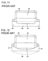
- the resilient receiving portions 106 are resiliently deformed in directions away from the locking projections 103 due to interference with the locking projections 103 as shown in FIG. 12 .
- the resilient receiving portions 106 are resiliently restored to be engaged with the locking projections 103 as shown in FIG. 11 and the holder 104 and the housing 100 are locked in an assembled state by this locking action.
- opposite end parts of the resilient receiving portion 106 serve as linking portions 107 linked to the inner surface of the lock hole 105.
- the linking portions 107 are deformed to a large extent as shown in FIG. 12 .
- stresses are concentrated on the linking portions 107 and improper deformation or breakage such as a crack may occur. If improper deformation, breakage or the like of the linking portions 107 occurs, the reliability of a lock function by the engagement of the resilient receiving portion 106 and the lock projection 102 is reduced.
- the present invention was completed in view of the above situation and an object thereof is to provide a connector with excellent reliability in a lock function.
- a connector comprising: a housing including at least one terminal accommodating chamber; at least one connector forming member to be assembled with the housing; at least one lock projection formed to project from either one of the housing and the connector forming member; at least one lock hole formed in the other of the housing and the connector forming member and enabling the at least partial insertion of the lock projection; at least one resiliently deformable resilient receiving portion arranged to traverse an opening area of the lock hole and linked to the inner surface of the lock hole at linking portions on substantially opposite ends in a longitudinal direction; at least one locking portion substantially projecting in the form of a rib along the longitudinal direction of the resilient receiving portion from the lock projection and configured to press the resilient receiving portion to resiliently curve and deform the resilient receiving portion in the process of assembling the housing and the connector forming member; and one or more escaping edge portions formed on the locking portion in a longitudinal direction, oblique to the longitudinal direction of the resilient receiving portion that is not resiliently deformed, and arranged to substantially face the linking portions.
- the escaping edge portion is not formed on the projecting edge portion of the locking portion, the opposite ends of the projecting end edge come into contact with the resilient receiving portion when the resilient receiving portion is curved and deformed to the maximum extent. Contrary to this, if the escaping edge portion is formed on the opposite ends of the projecting edge portion, the escaping edge portion comes into contact with the resilient receiving portion when the resilient receiving portion is curved and deformed to the maximum extent. Therefore, a lock function by the engagement of the resilient receiving portion and the lock projection has excellent reliability.
- plural escaping edge portions are formed on opposite ends of a projecting edge portion of the locking portion in a longitudinal direction.
- the escaping edge portion may come into contact with the resilient receiving portion at positions closer to the center than the opposite ends of the projecting edge portion.
- a spacing between the two lateral (left and right) contact positions of the escaping edge portions with the resilient receiving portion may be narrower than a spacing (i.e. maximum width of the locking portion) between two contact positions of the projecting edge portion (i.e. opposite ends of the projecting end edge) when the escaping edge portions are not formed.
- the spacing between the two contact positions of the projecting edge portion with the resilient receiving portion becomes narrower, the amount of resilient deformation of the resilient receiving portion may be reduced and/or stresses generated on the linking portions on the opposite ends of the resilient receiving portion are reduced.
- improper deformation, breakage and the like of the linking portions can further be prevented. Therefore, a lock function by the engagement of the resilient receiving portion and the lock projection has excellent reliability.
- a connector comprising a housing including a terminal accommodating chamber; a connector forming member to be assembled with the housing; a lock projection formed to project from either one of the housing and the connector forming member; a lock hole formed in the other of the housing and the connector forming member and enabling the insertion of the lock projection; a resiliently deformable resilient receiving portion arranged to traverse an opening area of the lock hole and linked to the inner surface of the lock hole at linking portions on opposite ends in a longitudinal direction; a locking portion projecting in the form of a rib along the longitudinal direction of the resilient receiving portion from the lock projection and configured to press the resilient receiving portion to resiliently curve and deform the resilient receiving portion in the process of assembling the housing and the connector forming member; and escaping edge portions formed on opposite ends of a projecting edge portion of the locking portion in a longitudinal direction, oblique to the longitudinal direction of the resilient receiving portion that is not resiliently deformed, and arranged to face the linking portions.
- the escaping edge portions are not formed on the projecting edge portion of the locking portion, the opposite ends of the projecting end edge come into contact with the resilient receiving portion when the resilient receiving portion is curved and deformed to the maximum extent. Contrary to this, if the escaping edge portions are formed on the opposite ends of the projecting edge portion, the escaping edge portions come into contact with the resilient receiving portion when the resilient receiving portion is curved and deformed to the maximum extent. The escaping edge portions come into contact with the resilient receiving portion at positions closer to the center than the opposite ends of the projecting edge portion. Thus, a spacing between the two left and right contact positions of the escaping edge portions with the resilient receiving portion is narrower than a spacing (i.e.
- one or more cut portions for locally reducing the width of the resilient receiving portion at the linking portions.
- the width of the resilient receiving portion is locally reduced at the linking portions, stresses generated when the resilient receiving portion is resiliently deformed are reduced. This reliably prevents improper deformation, breakage and the like at the linking portions and improves the reliability of the lock function.
- the cut portions are formed by cutting a warping edge portion, which is concavely curved and deformed, out of two warping edge portions which substantially extend along the longitudinal direction of the resilient receiving portion and are curved and deformed when the resilient receiving portion is resiliently deformed.
- a spacing between contact positions of the escaping edge portions with the resilient receiving portion is narrower than a maximum width of the locking portion.
- the escaping edge portion is substantially arcuate or bent or rounded.
- the escaping edge portion is arranged at a position closer to the center than the linking portions on the concave deformation side warping edge portion of the lock projection.
- the connector further comprises a resilient member to be held in contact with the housing, wherein the connector forming member is adapted to hold the resilient member thereby at least partly sandwiching the resilient member between the connector forming member and the housing.
- the connector forming member is formed with at least one insertion hole corresponding to the terminal accommodating chamber.
- a connector A of this embodiment includes a housing 10 made e.g. of synthetic resin and including one or more, particularly a plurality of terminal accommodating chambers 11, a resilient member (particularly a one-piece rubber plug) 20 provided to be held in contact with the rear surface of the housing 10, a holder 30 (as a particular connector forming member) made e.g.
- a connecting side with a mating connector is referred to as front or front side.
- the housing 10 is formed with one or more, particularly a pair of vertically symmetric lock projections 12 substantially projecting backward from the rear surface of the housing 10.
- the resilient member (particularly the one-piece rubber plug) 20 is formed with one or more, particularly a plurality of seal holes 21 particularly substantially in the form of through holes corresponding to the respective terminal accommodating chambers 11 as shown in FIGS. 1 and 2 and one or more, particularly a pair of vertically symmetric through holes 22 for allowing penetration of the lock projection(s) 12 as shown in FIG. 4 . As shown in FIGS.
- the holder 30 is formed with one or more, particularly a plurality of insertion holes 31 particularly substantially in the form of through holes corresponding to the respective terminal accommodating chamber(s) 11 and/or the seal hole(s) 21 and one or more, particularly a pair of vertically symmetric lock holes 32 particularly substantially in the form of through holes with which the lock projections 12 are to be engaged.
- the lock projection(s) 12 is/are engaged with the lock hole(s) 32, whereby the holder 30 is locked in an assembled state with the housing 10 and the resilient member (particularly the one-piece rubber plug) 20 is held in the assembled state.
- the connector A of this embodiment adopts a locking structure for locking the lock projection(s) 12 passed through the one-piece rubber plug 20 with the lock hole(s) 32, the outer peripheral surface of the resilient member (particularly the one-piece rubber plug) 20 is or can be held substantially in close contact with the inner periphery of a fitting tube portion of a mating connector (not shown) to which the connector A of this embodiment is to be connected.
- lock projection(s) 12 is described. Note that since the pair of lock projections 12 particularly are vertically symmetric, the lock projection 12 arranged at a lower side is described, but the lock projection 12 arranged at an upper side is not described below.
- the lock projection 12 is composed of or comprises a penetrating portion 13 which penetrates through the through hole 22 of the resilient member (particularly the one-piece rubber plug) 20 in a fluid or liquid tight manner and a lock portion 14 which substantially extends backward from the penetrating portion 13 and/or is to be at least partly inserted into the lock hole 32.
- the lock portion 14 particularly has a substantially laterally long rectangular rear shape (shape viewed in parallel to a projecting direction from the housing 10) in which a width (dimension in a horizontal direction HD) is larger than a vertical dimension (height).
- a locking portion 15 projecting in the form of a rib long in the horizontal direction HD particularly is formed at a projecting end part (rear end part) of the lock projection 12.
- the locking portion 15 projects laterally or downwardly (direction at an angle different from 0° or 180°, preferably substantially orthogonal to an assembling direction AD with the housing 10) particularly substantially over the entire width from the lateral or lower surface of the lock portion 14, and/or the rear surface of the locking portion 15 particularly is inclined with respect to an inserting direction ID of the lock projection 12 into the lock hole 32.
- the front surface of the locking portion 15 is at an angle different from 0° or 180°, preferably substantially perpendicular to the inserting direction ID of the lock projection 12 into the lock hole 32.
- a wide range of a projecting edge portion 16 (lower end edge) of the locking portion 15 excluding both left and right end parts particularly serves as a straight edge portion 17 horizontally extending substantially straight.
- a height difference between the lower surface of the lock portion 14 and the straight edge portion 17 i.e. a projecting distance of an area of the locking portion 15 where the straight edge portion 17 is formed from the lateral or lower surface of the lock portion 14
- a height difference between the lower surface of the lock portion 14 and the straight edge portion 17 particularly is substantially constant over the entire width of the straight edge portion 17.
- lock hole 32 is described. Note that since the pair of lock holes 32 particularly substantially are vertically symmetric, the lock hole 32 arranged at a lower side is described, but the lock hole 32 arranged at an upper side is not described below.
- an opening area of) the lock hole 32 is such that a positioning area 33 which particularly substantially has a laterally long rectangular shape and/or into which the lock portion 14 at least partly is to be tightly fitted and a locking area 34 which particularly substantially has a laterally long rectangular shape and/or is so arranged below the positioning area 33 as to communicate with the positioning area 33 substantially vertically communicate.
- the width of the locking area 34 particularly is larger than that of the positioning area 33, and both lateral (left and right) end parts of the locking area 34 project outwardly from those of the positioning area 33 in the width direction WD.
- the opening of the positioning area 33 particularly substantially has the same shape and/or the same dimension on the front and rear surfaces of the holder 30.
- the opening width of the locking area 34 on the front surface of the holder 30 particularly substantially is equal to that of the locking area 34 on the rear surface of the holder 30.
- a vertical opening range of the locking area 34 particularly extends more downward on the front surface of the holder 30 (surface closer to the housing 10) than on the rear surface of the holder 30. That is, as shown in FIG. 4 , a front side of the inner surface at the lower side (lower surface) of the lock hole 32 is lower than a rear side thereof with a step formed between the front and rear sides.
- a (particularly substantially long and narrow) resilient receiving portion 35 arranged to traverse the locking area 34 in a lateral direction (direction crossing both the inserting direction ID of the lock projection 12 into the lock hole 32 and a projecting direction of the locking portion 15 from the lock projection 12) is formed in or at the lock hole 32.
- the resilient receiving portion 35 particularly is linked to both lateral (left and right) inner side surfaces of the locking area 34 at linking portions 36 on substantially opposite end parts of the resilient receiving portion 35 in its longitudinal direction LD (width direction WD).
- a part of the resilient receiving portion 35 excluding the linking portions 36 on the opposite ends particularly serves as a deforming portion 37. That is, the linking portions 36 and the deforming portion 37 constitute or form part of the resilient receiving portion 35.
- the upper surface of the deforming portion 37 particularly is at an angle different from 0° or 180°, preferably substantially at a right angle to the inserting direction ID of the lock projection 12 into the lock hole 32.
- the resilient receiving portion 35 is so formed that the deforming portion 37 is resiliently deformable to be curved downwardly or outwardly (direction crossing the inserting direction ID of the lock projection 12 into the lock hole 32).
- the resilient receiving portion 35 is arranged at a front end side in the locking area 34. As shown in FIGS. 4 to 7 , a space of the locking area 34 below the resilient receiving portion 35 particularly serves as a deformation space 38 for permitting a curved deformation of the resilient receiving portion 35 to project downwardly.
- the upper surface (surface located in the positioning area 33 and substantially facing the lock portion 14) of the resilient receiving portion 35 particularly serves as a concave deformation side warping edge portion 39 which substantially extends in the longitudinal direction LD particularly over the substantially entire length of the resilient receiving portion 35 and/or particularly is concavely curved and deformed when the resilient receiving portion 35 is resiliently deformed.
- the lower surface of the resilient receiving portion 35 particularly serves as a convex deformation side warping edge portion 40 which substantially extends in the longitudinal direction LD particularly over the substantially entire length of the resilient receiving portion 35 and/or particularly is convexly curved and deformed when the resilient receiving portion 35 is resiliently deformed.
- the concave deformation side warping edge portion 39 and/or the convex deformation side warping edge portion 40 particularly substantially are both horizontal and flat surfaces in a state where the resilient receiving portion 35 is not resiliently deformed.
- the lock portion(s) 14 is/are at least partly inserted into the lock hole(s) 32 and/or the locking portion(s) 15 come into contact with the resilient receiving portion(s) 35. Thereafter, as the assembling of the holder 30 proceeds, the locking portion(s) 15 press(es) the resilient receiving portion(s) 35, wherefore the resilient receiving portion(s) 35 is/are curved and deformed.
- the resilient receiving portion 35 particularly is curved and deformed to project in a direction away from the lock portion 14 (downwardly or outwardly) in the lower lock hole 32, and the resilient receiving portion 35 is curved and deformed to project upwardly or outwardly in the upper lock hole 32.
- the resilient receiving portion(s) 35 is/are resiliently deformed to a maximum extent (i.e. a radius of curvature of the warping edge portions are smallest).
- the locking portion(s) 15 pass(es) the resilient receiving portion(s) 35 as shown in FIG. 4 , wherefore the resilient receiving portion(s) 35 is/are resiliently at least partly restored due to its/their resilient restoring forces. Since the resilient receiving portion(s) 35 particularly is/are engaged with (come into contact with or are proximately facing) the locking portion(s) 15 from front as shown in FIGS. 4 and 5 in this way, the holder 30 is locked in the assembled state by this locking action.
- the opposite end parts of the resilient receiving portion 35 particularly serve as the linking portions 36 linked to the inner surface of the lock hole 32.
- the deforming portion 37 is also curved and deformed as shown in FIG. 6 .
- the amount of deformation and stresses of the linking portions 36 are larger than those of the deformation portion 37. Due to this concentration of stresses, the linking portions 36 may undergo improper deformation or breakage such as cracks. If the linking portions 36 are improperly deformed or broken, the reliability of the lock function by the engagement of the resilient receiving portion 35 and the lock projection 12 is reduced.
- a measure against that particularly is provided at the lock projection 12 and the lock hole 32 (resilient receiving portion 35). This is described in detail below.
- the locking portion 15 presses the resilient receiving portion 35 at the both lateral (left and right) end parts of the projecting edge portion 16 thereof.
- the linking portions 36 on the substantially opposite ends of the resilient receiving portion 35 particularly are located at the outer sides of the lateral (left and right) ends of the locking portions 15 in the width direction WD.
- one or more escaping edge portions 18 which particularly are oblique to the straight edge portion 17 (longitudinal direction LD of the resilient receiving portion 35) when the resilient receiving portion 35 is not resiliently deformed and/or arranged to substantially face the linking portions 36 when viewed from behind (direction parallel to the inserting direction ID of the lock projection 12 into the lock hole 32) particularly substantially are bilaterally symmetrically formed on the both lateral (left and right) end parts of the projecting edge portion 16 of the locking portion 15.
- These escaping edge portions 18 particularly are substantially arcuate or bent or rounded and/or arranged at positions closer to the center than the linking portions 36 on the concave deformation side warping edge portion 39 of the lock projection 12.
- the escaping edge portions 18 and the straight edge portion 17 form (or form part of) the projecting edge portion 16 of the locking portion 15.
- the escaping edge portions 18 are not formed on the projecting edge portion 16 of the locking portion 15, the opposite ends of the projecting end edge come into contact with the resilient receiving portion 35 when the resilient receiving portion 35 is curved and deformed to the maximum extent. Contrary to this, if the escaping edge portions 18 are formed on the opposite ends of the projecting edge portion 16, the escaping edge portions 18 come into contact with the resilient receiving portion 35 when the resilient receiving portion 35 is curved and deformed to the maximum extent.
- the escaping edge portions 18 particularly substantially come into contact with the resilient receiving portion 35 at positions closer to the center than the opposite ends of the projecting edge portion 16. Thus, a spacing between the two lateral (left and right) contact positions of the escaping edge portions 18 with the resilient receiving portion 35 particularly is narrower than a spacing (i.e.
- the resilient receiving portion 35 particularly is formed with one or more cut portions 41 which locally reduce(s) the width of the resilient receiving portion 35 (dimension substantially parallel to a displacing direction when the resilient receiving portion 35 is resiliently deformed by being pressed by the locking portion 15) at the linking portions 36.
- a crack often occurs due to the action of a tensile load on the concave deformation side warping edge portion 39, which is concavely curved and deformed, out of the two warping edge portions 39, 40 that are curved and deformed.
- the one or more cut portions 41 of this embodiment particularly are formed by cutting the concave deformation side warping edge portion 39 that is concavely curved and deformed out of the two warping edge portions 39, 40 that extend in the longitudinal direction of the resilient receiving portion 35 and are curved and deformed when the resilient receiving portion 35 is resiliently deformed.
- the width of the resilient receiving portion 35 is locally reduced at the linking portions 36.
- stresses generated when the resilient receiving portion 35 is resiliently deformed are reduced. This reliably prevents improper deformation, breakage and the like at the linking portions 36 and improves the reliability of the lock function.
- the cut portions 41 particularly are formed by recessing the concave deformation side warping edge portion 39 that is concavely curved and deformed and is often cracked due to the action of a tensile load, improper deformation and breakage at the linking portions 36 can be more effectively prevented.
- a connector A includes at least one resiliently deformable resilient receiving portion 35 arranged to traverse an opening area of at least one lock hole 32 formed in a holder 30 (as a particular connector forming member) and linked to the inner surface of the lock hole 32 at linking portions 36 on opposite ends in a longitudinal direction LD, at least one locking portion 15 substantially projecting in the form of a rib along the longitudinal direction LD of the resilient receiving portion 35 from a lock projection 12 formed in a housing 10 and configured to press the resilient receiving portion 35 to resiliently curve and deform the resilient receiving portion 35 in the process of assembling the housing 10 and the holder 30, and one or more escaping edge portions 18 formed on (particularly substantially opposite ends of) a projecting edge portion 16 of the locking portion 15 in a longitudinal direction LD, oblique to the longitudinal direction LD of the resilient receiving portion 35 that is not resiliently deformed, and arranged to substantially face the linking portions 36.
Landscapes
- Connector Housings Or Holding Contact Members (AREA)
- Details Of Connecting Devices For Male And Female Coupling (AREA)
Abstract
Description
- The present invention relates to a connector.
- Japanese Unexamined Patent Publication No.
2002-110289 - In the connector disclosed in Japanese Unexamined Patent Publication No.
2002-110289 FIGS. 9 to 12 is thought as a locking means for engaging a lock projection with a lock hole without resiliently deforming the lock projection. As shown inFIG. 9 , ahousing 100 is formed withlock projections 102 projecting from the rear surface thereof and passing through a one-piece rubber plug 101, and alocking projection 103 projecting in a direction crossing a projecting direction of thelock projection 102 is formed at a projecting end part of eachlock projection 102. On the other hand, as shown inFIGS. 11 and 12 , aholder 104 is formed with resilientreceiving portions 106 which traverse in a direction crossing projecting directions of thelock projections 102 inlock holes 105 and have opposite ends supported on the inner surfaces of thelock holes 105. - When the
lock projections 102 is inserted into thelock holes 105 in the process of mounting theholder 104 into thehousing 100, the resilient receivingportions 106 are resiliently deformed in directions away from thelocking projections 103 due to interference with thelocking projections 103 as shown inFIG. 12 . When theholder 104 is properly assembled, the resilient receivingportions 106 are resiliently restored to be engaged with thelocking projections 103 as shown inFIG. 11 and theholder 104 and thehousing 100 are locked in an assembled state by this locking action. - In the above locking structure, opposite end parts of the resilient receiving
portion 106 serve as linkingportions 107 linked to the inner surface of thelock hole 105. When the resilient receivingportion 106 is resiliently deformed, the linkingportions 107 are deformed to a large extent as shown inFIG. 12 . Thus, stresses are concentrated on the linkingportions 107 and improper deformation or breakage such as a crack may occur. If improper deformation, breakage or the like of the linkingportions 107 occurs, the reliability of a lock function by the engagement of the resilient receivingportion 106 and thelock projection 102 is reduced. - The present invention was completed in view of the above situation and an object thereof is to provide a connector with excellent reliability in a lock function.
- This object is solved according to the invention by the features of the independent claim. Particular embodiments of the invention are subject of the dependent claims.
- According to the invention, there is provided a connector, comprising: a housing including at least one terminal accommodating chamber; at least one connector forming member to be assembled with the housing; at least one lock projection formed to project from either one of the housing and the connector forming member; at least one lock hole formed in the other of the housing and the connector forming member and enabling the at least partial insertion of the lock projection; at least one resiliently deformable resilient receiving portion arranged to traverse an opening area of the lock hole and linked to the inner surface of the lock hole at linking portions on substantially opposite ends in a longitudinal direction; at least one locking portion substantially projecting in the form of a rib along the longitudinal direction of the resilient receiving portion from the lock projection and configured to press the resilient receiving portion to resiliently curve and deform the resilient receiving portion in the process of assembling the housing and the connector forming member; and one or more escaping edge portions formed on the locking portion in a longitudinal direction, oblique to the longitudinal direction of the resilient receiving portion that is not resiliently deformed, and arranged to substantially face the linking portions.
- If the escaping edge portion is not formed on the projecting edge portion of the locking portion, the opposite ends of the projecting end edge come into contact with the resilient receiving portion when the resilient receiving portion is curved and deformed to the maximum extent. Contrary to this, if the escaping edge portion is formed on the opposite ends of the projecting edge portion, the escaping edge portion comes into contact with the resilient receiving portion when the resilient receiving portion is curved and deformed to the maximum extent. Therefore, a lock function by the engagement of the resilient receiving portion and the lock projection has excellent reliability.
- According to a particular embodiment, plural escaping edge portions are formed on opposite ends of a projecting edge portion of the locking portion in a longitudinal direction.
- The escaping edge portion may come into contact with the resilient receiving portion at positions closer to the center than the opposite ends of the projecting edge portion. Thus, a spacing between the two lateral (left and right) contact positions of the escaping edge portions with the resilient receiving portion may be narrower than a spacing (i.e. maximum width of the locking portion) between two contact positions of the projecting edge portion (i.e. opposite ends of the projecting end edge) when the escaping edge portions are not formed. As the spacing between the two contact positions of the projecting edge portion with the resilient receiving portion becomes narrower, the amount of resilient deformation of the resilient receiving portion may be reduced and/or stresses generated on the linking portions on the opposite ends of the resilient receiving portion are reduced. Thus, improper deformation, breakage and the like of the linking portions can further be prevented. Therefore, a lock function by the engagement of the resilient receiving portion and the lock projection has excellent reliability.
- According to a further particular embodiment, there is provided a connector, comprising a housing including a terminal accommodating chamber; a connector forming member to be assembled with the housing; a lock projection formed to project from either one of the housing and the connector forming member; a lock hole formed in the other of the housing and the connector forming member and enabling the insertion of the lock projection; a resiliently deformable resilient receiving portion arranged to traverse an opening area of the lock hole and linked to the inner surface of the lock hole at linking portions on opposite ends in a longitudinal direction; a locking portion projecting in the form of a rib along the longitudinal direction of the resilient receiving portion from the lock projection and configured to press the resilient receiving portion to resiliently curve and deform the resilient receiving portion in the process of assembling the housing and the connector forming member; and escaping edge portions formed on opposite ends of a projecting edge portion of the locking portion in a longitudinal direction, oblique to the longitudinal direction of the resilient receiving portion that is not resiliently deformed, and arranged to face the linking portions.
- If the escaping edge portions are not formed on the projecting edge portion of the locking portion, the opposite ends of the projecting end edge come into contact with the resilient receiving portion when the resilient receiving portion is curved and deformed to the maximum extent. Contrary to this, if the escaping edge portions are formed on the opposite ends of the projecting edge portion, the escaping edge portions come into contact with the resilient receiving portion when the resilient receiving portion is curved and deformed to the maximum extent. The escaping edge portions come into contact with the resilient receiving portion at positions closer to the center than the opposite ends of the projecting edge portion. Thus, a spacing between the two left and right contact positions of the escaping edge portions with the resilient receiving portion is narrower than a spacing (i.e. maximum width of the locking portion) between two contact positions of the projecting edge portion (i.e. opposite ends of the projecting end edge) when the escaping edge portions are not formed. As the spacing between the two contact positions of the projecting edge portion with the resilient receiving portion becomes narrower, the amount of resilient deformation of the resilient receiving portion is reduced and stresses generated on the linking portions on the opposite ends of the resilient receiving portion are reduced. Thus, improper deformation, breakage and the like of the linking portions are prevented. Therefore, a lock function by the engagement of the resilient receiving portion and the lock projection has excellent reliability.
- Particularly, there are further provided one or more cut portions for locally reducing the width of the resilient receiving portion at the linking portions.
- Since the width of the resilient receiving portion is locally reduced at the linking portions, stresses generated when the resilient receiving portion is resiliently deformed are reduced. This reliably prevents improper deformation, breakage and the like at the linking portions and improves the reliability of the lock function.
- Further particularly, the cut portions are formed by cutting a warping edge portion, which is concavely curved and deformed, out of two warping edge portions which substantially extend along the longitudinal direction of the resilient receiving portion and are curved and deformed when the resilient receiving portion is resiliently deformed.
- As the form of improper deformation and breakage caused due to an increase in stresses at the linking portions, a crack often occurs due to the action of a tensile load on the warping edge portion, which is concavely curved and deformed, out of the two warping edge portions that are curved and deformed. In view of this point, in the present invention, the warping edge portion that is concavely curved and deformed is recessed. Therefore, improper deformation and breakage at the linking portions can be more effectively prevented.
- Further particularly, a spacing between contact positions of the escaping edge portions with the resilient receiving portion is narrower than a maximum width of the locking portion.
- Further particularly, the escaping edge portion is substantially arcuate or bent or rounded.
- Further particularly, the escaping edge portion is arranged at a position closer to the center than the linking portions on the concave deformation side warping edge portion of the lock projection.
- Further particularly, the connector further comprises a resilient member to be held in contact with the housing, wherein the connector forming member is adapted to hold the resilient member thereby at least partly sandwiching the resilient member between the connector forming member and the housing.
- Further particularly, the connector forming member is formed with at least one insertion hole corresponding to the terminal accommodating chamber.
- These and other objects, features and advantages of the present invention will become more apparent upon reading of the following detailed description of preferred embodiments and accompanying drawings. It should be understood that even though embodiments are separately described, single features thereof may be combined to additional embodiments.
-
FIG. 1 is a rear view of a connector according to one embodiment, -
FIG. 2 is a rear view showing a state where resilient receiving portions are resiliently deformed, -
FIG. 3 is a rear view of a holder, -
FIG. 4 is a section of the connector, -
FIG. 5 is a partial enlarged rear view ofFIG. 1 , -
FIG. 6 is a partial enlarged rear view ofFIG. 2 , -
FIG. 7 is an enlarged rear view showing the shapes of a lock hole and the resilient receiving portion, -
FIG. 8 is an enlarged rear view showing the shape of a lock projection, -
FIG. 9 is a section of a conventional connector, -
FIG. 10 is a rear view of the conventional connector, -
FIG. 11 is a partial enlarged rear view ofFIG. 10 , and -
FIG. 12 is a partial enlarged rear view of the conventional connector showing a state where a resilient receiving portion is resiliently deformed. - Hereinafter, one specific embodiment of the present invention is described in detail with reference to
FIGS. 1 to 8 . As shown inFIG. 4 , a connector A of this embodiment includes ahousing 10 made e.g. of synthetic resin and including one or more, particularly a plurality ofterminal accommodating chambers 11, a resilient member (particularly a one-piece rubber plug) 20 provided to be held in contact with the rear surface of thehousing 10, a holder 30 (as a particular connector forming member) made e.g. of synthetic resin and adapted to hold the resilient member (particularly the one-piece rubber plug) 20 by at least partly sandwiching the resilient member (particularly the one-piece rubber plug) 20 between theholder 30 and the rear surface of thehousing 10 substantially from front and rear sides, and one or more terminal fittings (not shown) of a known form. In the following, a connecting side with a mating connector (not shown) is referred to as front or front side. - The
housing 10 is formed with one or more, particularly a pair of verticallysymmetric lock projections 12 substantially projecting backward from the rear surface of thehousing 10. The resilient member (particularly the one-piece rubber plug) 20 is formed with one or more, particularly a plurality of seal holes 21 particularly substantially in the form of through holes corresponding to the respectiveterminal accommodating chambers 11 as shown inFIGS. 1 and2 and one or more, particularly a pair of vertically symmetric throughholes 22 for allowing penetration of the lock projection(s) 12 as shown inFIG. 4 . As shown inFIGS. 1 to 3 , theholder 30 is formed with one or more, particularly a plurality of insertion holes 31 particularly substantially in the form of through holes corresponding to the respective terminal accommodating chamber(s) 11 and/or the seal hole(s) 21 and one or more, particularly a pair of vertically symmetric lock holes 32 particularly substantially in the form of through holes with which thelock projections 12 are to be engaged. - As shown in
FIG. 4 , in a state where thehousing 10, the resilient member (particularly the one-piece rubber plug) 20 and theholder 30 are assembled, the lock projection(s) 12 is/are engaged with the lock hole(s) 32, whereby theholder 30 is locked in an assembled state with thehousing 10 and the resilient member (particularly the one-piece rubber plug) 20 is held in the assembled state. Since the connector A of this embodiment adopts a locking structure for locking the lock projection(s) 12 passed through the one-piece rubber plug 20 with the lock hole(s) 32, the outer peripheral surface of the resilient member (particularly the one-piece rubber plug) 20 is or can be held substantially in close contact with the inner periphery of a fitting tube portion of a mating connector (not shown) to which the connector A of this embodiment is to be connected. - Next, the detailed form of the lock projection(s) 12 is described. Note that since the pair of
lock projections 12 particularly are vertically symmetric, thelock projection 12 arranged at a lower side is described, but thelock projection 12 arranged at an upper side is not described below. - As shown in
FIG. 4 , thelock projection 12 is composed of or comprises a penetratingportion 13 which penetrates through the throughhole 22 of the resilient member (particularly the one-piece rubber plug) 20 in a fluid or liquid tight manner and alock portion 14 which substantially extends backward from the penetratingportion 13 and/or is to be at least partly inserted into thelock hole 32. As shown inFIGS. 5, 6 and8 , thelock portion 14 particularly has a substantially laterally long rectangular rear shape (shape viewed in parallel to a projecting direction from the housing 10) in which a width (dimension in a horizontal direction HD) is larger than a vertical dimension (height). A lockingportion 15 projecting in the form of a rib long in the horizontal direction HD particularly is formed at a projecting end part (rear end part) of thelock projection 12. - The locking
portion 15 projects laterally or downwardly (direction at an angle different from 0° or 180°, preferably substantially orthogonal to an assembling direction AD with the housing 10) particularly substantially over the entire width from the lateral or lower surface of thelock portion 14, and/or the rear surface of the lockingportion 15 particularly is inclined with respect to an inserting direction ID of thelock projection 12 into thelock hole 32. The front surface of the lockingportion 15 is at an angle different from 0° or 180°, preferably substantially perpendicular to the inserting direction ID of thelock projection 12 into thelock hole 32. A wide range of a projecting edge portion 16 (lower end edge) of the lockingportion 15 excluding both left and right end parts particularly serves as astraight edge portion 17 horizontally extending substantially straight. A height difference between the lower surface of thelock portion 14 and the straight edge portion 17 (i.e. a projecting distance of an area of the lockingportion 15 where thestraight edge portion 17 is formed from the lateral or lower surface of the lock portion 14) particularly is substantially constant over the entire width of thestraight edge portion 17. - Next, the detailed form of the
lock hole 32 is described. Note that since the pair of lock holes 32 particularly substantially are vertically symmetric, thelock hole 32 arranged at a lower side is described, but thelock hole 32 arranged at an upper side is not described below. - As shown in
FIGS. 5 to 7 , (an opening area of) thelock hole 32 is such that apositioning area 33 which particularly substantially has a laterally long rectangular shape and/or into which thelock portion 14 at least partly is to be tightly fitted and a lockingarea 34 which particularly substantially has a laterally long rectangular shape and/or is so arranged below thepositioning area 33 as to communicate with thepositioning area 33 substantially vertically communicate. The width of the lockingarea 34 particularly is larger than that of thepositioning area 33, and both lateral (left and right) end parts of the lockingarea 34 project outwardly from those of thepositioning area 33 in the width direction WD. Further, the opening of thepositioning area 33 particularly substantially has the same shape and/or the same dimension on the front and rear surfaces of theholder 30. - The opening width of the locking
area 34 on the front surface of theholder 30 particularly substantially is equal to that of the lockingarea 34 on the rear surface of theholder 30. However, a vertical opening range of the lockingarea 34 particularly extends more downward on the front surface of the holder 30 (surface closer to the housing 10) than on the rear surface of theholder 30. That is, as shown inFIG. 4 , a front side of the inner surface at the lower side (lower surface) of thelock hole 32 is lower than a rear side thereof with a step formed between the front and rear sides. - As shown in
FIGS. 5 to 7 , a (particularly substantially long and narrow) resilient receivingportion 35 arranged to traverse the lockingarea 34 in a lateral direction (direction crossing both the inserting direction ID of thelock projection 12 into thelock hole 32 and a projecting direction of the lockingportion 15 from the lock projection 12) is formed in or at thelock hole 32. The resilient receivingportion 35 particularly is linked to both lateral (left and right) inner side surfaces of the lockingarea 34 at linkingportions 36 on substantially opposite end parts of the resilient receivingportion 35 in its longitudinal direction LD (width direction WD). A part of the resilient receivingportion 35 excluding the linkingportions 36 on the opposite ends particularly serves as a deformingportion 37. That is, the linkingportions 36 and the deformingportion 37 constitute or form part of the resilient receivingportion 35. Further, the upper surface of the deformingportion 37 particularly is at an angle different from 0° or 180°, preferably substantially at a right angle to the inserting direction ID of thelock projection 12 into thelock hole 32. - The resilient receiving
portion 35 is so formed that the deformingportion 37 is resiliently deformable to be curved downwardly or outwardly (direction crossing the inserting direction ID of thelock projection 12 into the lock hole 32). The resilient receivingportion 35 is arranged at a front end side in the lockingarea 34. As shown inFIGS. 4 to 7 , a space of the lockingarea 34 below the resilient receivingportion 35 particularly serves as adeformation space 38 for permitting a curved deformation of the resilient receivingportion 35 to project downwardly. - As shown in
FIGS. 5 to 7 , the upper surface (surface located in thepositioning area 33 and substantially facing the lock portion 14) of the resilient receivingportion 35 particularly serves as a concave deformation side warpingedge portion 39 which substantially extends in the longitudinal direction LD particularly over the substantially entire length of the resilient receivingportion 35 and/or particularly is concavely curved and deformed when the resilient receivingportion 35 is resiliently deformed. On the other hand, the lower surface of the resilient receivingportion 35 particularly serves as a convex deformation side warpingedge portion 40 which substantially extends in the longitudinal direction LD particularly over the substantially entire length of the resilient receivingportion 35 and/or particularly is convexly curved and deformed when the resilient receivingportion 35 is resiliently deformed. The concave deformation side warpingedge portion 39 and/or the convex deformation side warpingedge portion 40 particularly substantially are both horizontal and flat surfaces in a state where the resilient receivingportion 35 is not resiliently deformed. - In the process of assembling the
holder 30 with thehousing 10, in which the resilient member (particularly the one-piece rubber plug) 20 is mounted, particularly substantially from behind, the lock portion(s) 14 is/are at least partly inserted into the lock hole(s) 32 and/or the locking portion(s) 15 come into contact with the resilient receiving portion(s) 35. Thereafter, as the assembling of theholder 30 proceeds, the locking portion(s) 15 press(es) the resilient receiving portion(s) 35, wherefore the resilient receiving portion(s) 35 is/are curved and deformed. At this time, the resilient receivingportion 35 particularly is curved and deformed to project in a direction away from the lock portion 14 (downwardly or outwardly) in thelower lock hole 32, and the resilient receivingportion 35 is curved and deformed to project upwardly or outwardly in theupper lock hole 32. As the assembling of theholder 30 proceeds and the projecting edge portion(s) 16 of the locking portion(s) 15 come(s) into contact with the resilient receiving portion(s) 35 as shown inFIG. 6 , the resilient receiving portion(s) 35 is/are resiliently deformed to a maximum extent (i.e. a radius of curvature of the warping edge portions are smallest). - When the
holder 30 reaches a proper assembled position, the locking portion(s) 15 pass(es) the resilient receiving portion(s) 35 as shown inFIG. 4 , wherefore the resilient receiving portion(s) 35 is/are resiliently at least partly restored due to its/their resilient restoring forces. Since the resilient receiving portion(s) 35 particularly is/are engaged with (come into contact with or are proximately facing) the locking portion(s) 15 from front as shown inFIGS. 4 and5 in this way, theholder 30 is locked in the assembled state by this locking action. - In the locking structure of this embodiment, the opposite end parts of the resilient receiving
portion 35 particularly serve as the linkingportions 36 linked to the inner surface of thelock hole 32. When the resilient receivingportion 35 is resiliently deformed, the deformingportion 37 is also curved and deformed as shown inFIG. 6 . The amount of deformation and stresses of the linkingportions 36 are larger than those of thedeformation portion 37. Due to this concentration of stresses, the linkingportions 36 may undergo improper deformation or breakage such as cracks. If the linkingportions 36 are improperly deformed or broken, the reliability of the lock function by the engagement of the resilient receivingportion 35 and thelock projection 12 is reduced. Thus, in this embodiment, a measure against that particularly is provided at thelock projection 12 and the lock hole 32 (resilient receiving portion 35). This is described in detail below. - When the resilient receiving
portion 35 is resiliently deformed to the maximum extent in the process of assembling theholder 30, the lockingportion 15 presses the resilient receivingportion 35 at the both lateral (left and right) end parts of the projectingedge portion 16 thereof. Further, the linkingportions 36 on the substantially opposite ends of the resilient receivingportion 35 particularly are located at the outer sides of the lateral (left and right) ends of the lockingportions 15 in the width direction WD. Paying attention to these points, one or more escapingedge portions 18 which particularly are oblique to the straight edge portion 17 (longitudinal direction LD of the resilient receiving portion 35) when the resilient receivingportion 35 is not resiliently deformed and/or arranged to substantially face the linkingportions 36 when viewed from behind (direction parallel to the inserting direction ID of thelock projection 12 into the lock hole 32) particularly substantially are bilaterally symmetrically formed on the both lateral (left and right) end parts of the projectingedge portion 16 of the lockingportion 15. These escapingedge portions 18 particularly are substantially arcuate or bent or rounded and/or arranged at positions closer to the center than the linkingportions 36 on the concave deformation side warpingedge portion 39 of thelock projection 12. The escapingedge portions 18 and thestraight edge portion 17 form (or form part of) the projectingedge portion 16 of the lockingportion 15. - If the escaping
edge portions 18 are not formed on the projectingedge portion 16 of the lockingportion 15, the opposite ends of the projecting end edge come into contact with the resilient receivingportion 35 when the resilient receivingportion 35 is curved and deformed to the maximum extent. Contrary to this, if the escapingedge portions 18 are formed on the opposite ends of the projectingedge portion 16, the escapingedge portions 18 come into contact with the resilient receivingportion 35 when the resilient receivingportion 35 is curved and deformed to the maximum extent. The escapingedge portions 18 particularly substantially come into contact with the resilient receivingportion 35 at positions closer to the center than the opposite ends of the projectingedge portion 16. Thus, a spacing between the two lateral (left and right) contact positions of the escapingedge portions 18 with the resilient receivingportion 35 particularly is narrower than a spacing (i.e. maximum width of the locking portion 15) between two contact positions of the projecting edge portion 16 (i.e. substantially opposite ends of the projecting end edge) when the escapingedge portions 18 are not formed. As the spacing between the two contact positions of the projectingedge portion 16 with the resilient receivingportion 35 becomes narrower, the amount of resilient deformation of the resilient receivingportion 35 is reduced and stresses generated on the linkingportions 36 on the opposite ends of the resilient receivingportion 35 are reduced. Thus, improper deformation, breakage and the like of the linkingportions 36 are prevented. Therefore, the lock function by the engagement of the resilient receivingportion 35 and thelock projection 12 has excellent reliability. - Further, as a means for avoiding the concentration of stresses on the linking
portions 36, the resilient receivingportion 35 particularly is formed with one ormore cut portions 41 which locally reduce(s) the width of the resilient receiving portion 35 (dimension substantially parallel to a displacing direction when the resilient receivingportion 35 is resiliently deformed by being pressed by the locking portion 15) at the linkingportions 36. Further, as the form of improper deformation and breakage caused due to an increase in stresses at the linkingportions 36, a crack often occurs due to the action of a tensile load on the concave deformation side warpingedge portion 39, which is concavely curved and deformed, out of the two warpingedge portions more cut portions 41 of this embodiment particularly are formed by cutting the concave deformation side warpingedge portion 39 that is concavely curved and deformed out of the two warpingedge portions portion 35 and are curved and deformed when the resilient receivingportion 35 is resiliently deformed. - By particularly forming the
cut portions 41 in this way, the width of the resilient receivingportion 35 is locally reduced at the linkingportions 36. Thus, stresses generated when the resilient receivingportion 35 is resiliently deformed are reduced. This reliably prevents improper deformation, breakage and the like at the linkingportions 36 and improves the reliability of the lock function. In addition, since thecut portions 41 particularly are formed by recessing the concave deformation side warpingedge portion 39 that is concavely curved and deformed and is often cracked due to the action of a tensile load, improper deformation and breakage at the linkingportions 36 can be more effectively prevented. - Accordingly, to provide a connector with excellent reliability in a lock function, a connector A includes at least one resiliently deformable resilient receiving
portion 35 arranged to traverse an opening area of at least onelock hole 32 formed in a holder 30 (as a particular connector forming member) and linked to the inner surface of thelock hole 32 at linkingportions 36 on opposite ends in a longitudinal direction LD, at least one lockingportion 15 substantially projecting in the form of a rib along the longitudinal direction LD of the resilient receivingportion 35 from alock projection 12 formed in ahousing 10 and configured to press the resilient receivingportion 35 to resiliently curve and deform the resilient receivingportion 35 in the process of assembling thehousing 10 and theholder 30, and one or more escapingedge portions 18 formed on (particularly substantially opposite ends of) a projectingedge portion 16 of the lockingportion 15 in a longitudinal direction LD, oblique to the longitudinal direction LD of the resilient receivingportion 35 that is not resiliently deformed, and arranged to substantially face the linkingportions 36. - The present invention is not limited to the above described and illustrated embodiment. For example, the following embodiments are also included in the technical scope of the present invention.
- (1) Although the escaping edge portions are arcuate or bent in the above embodiment, they may be substantially straight.
- (2) Although the housing is formed with the one or more lock projections and the holder is formed with the one or more lock holes in the above embodiment, the holder may be formed with the one or more lock projections and the housing may be formed with the one or more lock holes.
- (3) Although the deformation space for the resilient receiving portion is open only in the front surface of the holder in the above embodiment, it may be open in the both front and rear surfaces of the holder or may be open only in the rear surface of the holder.
- (4) Although the cut portions for reducing the width of the linking portions particularly are formed only on the concave deformation side warping edge portion that is concavely curved and deformed out of the two warping edge portions extending along the longitudinal direction of the resilient receiving portion in the above embodiment, they may be formed only on the convex deformation side warping edge portion or may be formed on both the concave deformation side warping edge portion and the convex deformation side warping edge portion.
- (5) Although the cut portions particularly are formed by recessing the warping edge portion in the above embodiment, they may be holes penetrating through the linking portions instead of recesses on the warping edge portion.
- (6) Although the cut portions for reducing the width of the linking portions particularly are formed in the above embodiment, the width of the resilient receiving portion may be constant over the entire length without forming the cut portions at the linking portions.
- (7) Although the pair of lock projections and the pair of lock holes particularly substantially are vertically symmetric in the above embodiment, the pair of lock projections and the pair of lock holes may be asymmetric.
- (8) Although the pair of lock projections and the pair of lock holes particularly are provided in the above embodiment, one each of the lock projection and the lock hole may be provided or three or more of the lock projections and the lock holes may be provided.
- (9) Although the lock holes particularly substantially are in the form of through holes that are open in the rear surface of the holder in the above embodiment, they may be in the form of closed holes which are not open in the rear surface of the holder.
- (10) Although the housing and the holder particularly are locked in the assembled state in the above embodiment, the present invention is not limited to a combination of the housing and the holder and can be also applied in the case of assembling the housing and a member other than the holder (e.g. a retainer with a function of retaining the terminal fittings and a function of detecting inserted states of the terminal fittings or a front member forming front end parts of the terminal accommodating chambers in the housing).
-
- A
- connector
- 10
- housing
- 11
- terminal accommodating chamber
- 12
- lock projection
- 15
- locking portion
- 16
- projecting edge portion of locking portion
- 18
- escaping edge portion
- 30
- holder (connector forming member)
- 32
- lock hole
- 35
- resilient receiving portion
- 36
- linking portion
- 39
- concave deformation side warping edge portion (warping edge portion which is concavely curved and deformed)
- 40
- convex deformation side warping edge portion (warping edge portion)
- 41
- cut portion
Claims (9)
- A connector (A), comprising:a housing (10) including at least one terminal accommodating chamber (11);at least one connector forming member (30) to be assembled with the housing (10);at least one lock projection (12) formed to project from either one of the housing (10) and the connector forming member (30);at least one lock hole (32) formed in the other of the housing (10) and the connector forming member (30) and enabling the at least partial insertion of the lock projection (12);at least one resiliently deformable resilient receiving portion (35) arranged to traverse an opening area of the lock hole (32) and linked to the inner surface of the lock hole (32) at linking portions (36) on substantially opposite ends in a longitudinal direction (LD);at least one locking portion (15) substantially projecting in the form of a rib along the longitudinal direction (LD) of the resilient receiving portion (35) from the lock projection (12) and configured to press the resilient receiving portion (35) to resiliently curve and deform the resilient receiving portion (35) in the process of assembling the housing (10) and the connector forming member (30); andone or more escaping edge portions (18) formed on the locking portion (15) in a longitudinal direction (LD), oblique to the longitudinal direction (LD) of the resilient receiving portion (35) that is not resiliently deformed, and arranged to substantially face the linking portions (36).
- A connector according to claim 1, wherein plural escaping edge portions (18) are formed on opposite ends of a projecting edge portion (16) of the locking portion (15) in a longitudinal direction (LD).
- A connector according to any one of the preceding claims, further comprising one or more cut portions (41) for locally reducing the width of the resilient receiving portion (35) at the linking portions (36).
- A connector according to claim 3, wherein the cut portions (41) are formed by cutting a warping edge portion (39), which is concavely curved and deformed, out of two warping edge portions (39, 40) which substantially extend along the longitudinal direction (LD) of the resilient receiving portion (35) and are curved and deformed when the resilient receiving portion (35) is resiliently deformed.
- A connector according to any one of the preceding claims, wherein a spacing between contact positions of the escaping edge portions (18) with the resilient receiving portion (35) is narrower than a maximum width of the locking portion (15).
- A connector according to any one of the preceding claims, wherein the escaping edge portion (18) is substantially arcuate or bent or rounded.
- A connector according to any one of the preceding claims, wherein the escaping edge portion (18) is arranged at a position closer to the center than the linking portions (36) on the concave deformation side warping edge portion (39) of the lock projection (12).
- A connector according to any one of the preceding claims, further comprising a resilient member (20) to be held in contact with the housing (10), wherein the connector forming member (30) is adapted to hold the resilient member (20) thereby at least partly sandwiching the resilient member (20) between the connector forming member (30) and the housing (10).
- A connector according to claim 8, wherein the connector forming member (30) is formed with at least one insertion hole (31) corresponding to the terminal accommodating chamber (11).
Applications Claiming Priority (1)
| Application Number | Priority Date | Filing Date | Title |
|---|---|---|---|
| JP2011208290A JP5704031B2 (en) | 2011-09-24 | 2011-09-24 | connector |
Publications (2)
| Publication Number | Publication Date |
|---|---|
| EP2573879A1 true EP2573879A1 (en) | 2013-03-27 |
| EP2573879B1 EP2573879B1 (en) | 2015-09-16 |
Family
ID=47071041
Family Applications (1)
| Application Number | Title | Priority Date | Filing Date |
|---|---|---|---|
| EP12005852.4A Not-in-force EP2573879B1 (en) | 2011-09-24 | 2012-08-13 | Connector |
Country Status (5)
| Country | Link |
|---|---|
| US (1) | US8721373B2 (en) |
| EP (1) | EP2573879B1 (en) |
| JP (1) | JP5704031B2 (en) |
| KR (1) | KR101342229B1 (en) |
| CN (1) | CN103022791B (en) |
Families Citing this family (8)
| Publication number | Priority date | Publication date | Assignee | Title |
|---|---|---|---|---|
| JP5923898B2 (en) * | 2011-08-30 | 2016-05-25 | ブラザー工業株式会社 | Development device |
| JP5704031B2 (en) * | 2011-09-24 | 2015-04-22 | 住友電装株式会社 | connector |
| JP6243197B2 (en) * | 2013-11-12 | 2017-12-06 | 矢崎総業株式会社 | Battery cover |
| JP6358102B2 (en) * | 2015-01-14 | 2018-07-18 | 住友電装株式会社 | connector |
| JP6137737B2 (en) * | 2015-09-11 | 2017-05-31 | 株式会社安川電機 | Electrical equipment casing and power converter |
| JP2018200765A (en) * | 2017-05-25 | 2018-12-20 | 矢崎総業株式会社 | connector |
| JP6656206B2 (en) * | 2017-05-26 | 2020-03-04 | 矢崎総業株式会社 | connector |
| JP7087986B2 (en) * | 2018-12-21 | 2022-06-21 | 住友電装株式会社 | Split connector |
Citations (3)
| Publication number | Priority date | Publication date | Assignee | Title |
|---|---|---|---|---|
| JP2002110289A (en) | 2000-09-29 | 2002-04-12 | Sumitomo Wiring Syst Ltd | Connector |
| US20030176090A1 (en) * | 2002-03-18 | 2003-09-18 | Yazaki Corporation | Connector with cover |
| EP2112715A2 (en) * | 2008-04-23 | 2009-10-28 | Yazaki Corporation | Lock structure and cover lock structure of terminal cap |
Family Cites Families (35)
| Publication number | Priority date | Publication date | Assignee | Title |
|---|---|---|---|---|
| JPS58118684U (en) * | 1982-02-08 | 1983-08-12 | 住友電装株式会社 | connector |
| JP2509471Y2 (en) * | 1988-07-19 | 1996-09-04 | モレックス インコーポレーテッド | Waterproof electrical connector |
| US5782657A (en) * | 1995-04-13 | 1998-07-21 | The Whitaker Corporation | Electrical connector with secondary lock |
| US6004153A (en) * | 1996-03-27 | 1999-12-21 | The Whitaker Corporation | Electrical connector with connector position assurance device |
| JP3388569B2 (en) * | 1997-03-10 | 2003-03-24 | 矢崎総業株式会社 | Waterproof connector |
| US6004158A (en) * | 1997-03-27 | 1999-12-21 | The Whitaker Corporation | Electrical connector with secondary locking plates |
| US5928038A (en) * | 1998-04-24 | 1999-07-27 | Molex Incorporated | Electrical connector position assurance system |
| JP3983380B2 (en) * | 1998-06-08 | 2007-09-26 | 矢崎総業株式会社 | connector |
| JP3540164B2 (en) * | 1998-07-06 | 2004-07-07 | 矢崎総業株式会社 | Waterproof connector |
| JP3540197B2 (en) * | 1999-05-18 | 2004-07-07 | 矢崎総業株式会社 | Waterproof connector |
| JP3672229B2 (en) * | 2000-02-23 | 2005-07-20 | 矢崎総業株式会社 | Holder removal prevention connector |
| JP3777980B2 (en) | 2000-12-25 | 2006-05-24 | 住友電装株式会社 | Split connector |
| JP2002203643A (en) | 2000-12-28 | 2002-07-19 | Sumitomo Wiring Syst Ltd | Rubber stopper for waterproof connector |
| US6514098B2 (en) * | 2000-12-28 | 2003-02-04 | Tyco Electronics Corporation | Electrical connector with terminal and connector position assurance devices |
| JP3674774B2 (en) * | 2001-04-03 | 2005-07-20 | 住友電装株式会社 | connector |
| JP4089179B2 (en) * | 2001-06-06 | 2008-05-28 | 住友電装株式会社 | connector |
| JP2003031294A (en) * | 2001-07-12 | 2003-01-31 | Ryosei Electro-Circuit Systems Ltd | Waterproof connector |
| TWI255592B (en) * | 2002-08-23 | 2006-05-21 | Hon Hai Prec Ind Co Ltd | Electrical connector and method of making same |
| US6719590B1 (en) * | 2002-10-22 | 2004-04-13 | Hon Hai Precision Ind. Co., Ltd. | Electrical adapter |
| US6913486B2 (en) * | 2002-11-07 | 2005-07-05 | Sumitomo Wiring Systems, Ltd. | Waterproof electrical connector |
| US7201599B2 (en) * | 2004-03-23 | 2007-04-10 | Fci Americas Technology, Inc. | Electrical connector latch |
| JP2005317385A (en) * | 2004-04-28 | 2005-11-10 | Tyco Electronics Amp Kk | Waterproof connector and sealing member therefor |
| US7351102B2 (en) * | 2004-05-21 | 2008-04-01 | Delphi Technologies, Inc. | Electrical connector with terminal position assurance |
| JP4537966B2 (en) * | 2006-02-20 | 2010-09-08 | 矢崎総業株式会社 | Waterproof connector |
| DE102006017448A1 (en) * | 2006-04-13 | 2007-10-18 | Robert Bosch Gmbh | Plug with matt seal |
| JP4900026B2 (en) * | 2007-05-08 | 2012-03-21 | 住友電装株式会社 | connector |
| JP4924454B2 (en) * | 2008-01-29 | 2012-04-25 | 住友電装株式会社 | connector |
| CN102257681B (en) * | 2008-11-07 | 2013-09-04 | 富加宜汽车控股公司 | Sealed electrical connector |
| JP5423233B2 (en) * | 2009-08-18 | 2014-02-19 | 住友電装株式会社 | connector |
| JP5428730B2 (en) * | 2009-10-13 | 2014-02-26 | 住友電装株式会社 | Waterproof connector |
| JP5402861B2 (en) * | 2010-07-09 | 2014-01-29 | 住友電装株式会社 | connector |
| JP5569297B2 (en) * | 2010-09-24 | 2014-08-13 | 住友電装株式会社 | Waterproof connector |
| JP5625793B2 (en) * | 2010-11-18 | 2014-11-19 | 住友電装株式会社 | Waterproof connector |
| US8419485B2 (en) * | 2011-01-27 | 2013-04-16 | Tyco Electronics Corporation | Bulkhead connector assembly |
| JP5704031B2 (en) * | 2011-09-24 | 2015-04-22 | 住友電装株式会社 | connector |
-
2011
- 2011-09-24 JP JP2011208290A patent/JP5704031B2/en active Active
-
2012
- 2012-08-13 EP EP12005852.4A patent/EP2573879B1/en not_active Not-in-force
- 2012-09-12 US US13/611,032 patent/US8721373B2/en active Active
- 2012-09-24 KR KR1020120105730A patent/KR101342229B1/en not_active Expired - Fee Related
- 2012-09-24 CN CN201210359479.9A patent/CN103022791B/en active Active
Patent Citations (3)
| Publication number | Priority date | Publication date | Assignee | Title |
|---|---|---|---|---|
| JP2002110289A (en) | 2000-09-29 | 2002-04-12 | Sumitomo Wiring Syst Ltd | Connector |
| US20030176090A1 (en) * | 2002-03-18 | 2003-09-18 | Yazaki Corporation | Connector with cover |
| EP2112715A2 (en) * | 2008-04-23 | 2009-10-28 | Yazaki Corporation | Lock structure and cover lock structure of terminal cap |
Also Published As
| Publication number | Publication date |
|---|---|
| JP2013069592A (en) | 2013-04-18 |
| KR20130033315A (en) | 2013-04-03 |
| CN103022791A (en) | 2013-04-03 |
| JP5704031B2 (en) | 2015-04-22 |
| EP2573879B1 (en) | 2015-09-16 |
| US8721373B2 (en) | 2014-05-13 |
| KR101342229B1 (en) | 2013-12-16 |
| CN103022791B (en) | 2015-07-01 |
| US20130078843A1 (en) | 2013-03-28 |
Similar Documents
| Publication | Publication Date | Title |
|---|---|---|
| EP2573879B1 (en) | Connector | |
| US10615528B2 (en) | Electrical connector | |
| JP5388922B2 (en) | Connectors and electronic devices | |
| US8992235B2 (en) | Terminal fitting and a connection structure for a terminal fitting | |
| EP2511989A1 (en) | Connector and assembling method therefor | |
| TWI508393B (en) | Connectors and electronic machines | |
| EP2429041A1 (en) | Connector and method of producing it | |
| KR100972379B1 (en) | Connector and its assembly method | |
| CN107293875B (en) | Connector for substrate | |
| US8784133B2 (en) | Connector | |
| US20150017823A1 (en) | Connector | |
| US9387828B2 (en) | Adapter for windshield wiper assembly | |
| US11705654B2 (en) | Terminal fitting and chain terminal | |
| US10938156B2 (en) | Split connector | |
| US20130295791A1 (en) | Connector | |
| JP5067304B2 (en) | connector | |
| JP5939471B2 (en) | Terminal fitting | |
| JP2009123365A (en) | Connector | |
| US10069222B2 (en) | Terminal structure and female terminal | |
| JP2013073719A (en) | Connector | |
| JP2016012401A (en) | connector |
Legal Events
| Date | Code | Title | Description |
|---|---|---|---|
| PUAI | Public reference made under article 153(3) epc to a published international application that has entered the european phase |
Free format text: ORIGINAL CODE: 0009012 |
|
| AK | Designated contracting states |
Kind code of ref document: A1 Designated state(s): AL AT BE BG CH CY CZ DE DK EE ES FI FR GB GR HR HU IE IS IT LI LT LU LV MC MK MT NL NO PL PT RO RS SE SI SK SM TR |
|
| AX | Request for extension of the european patent |
Extension state: BA ME |
|
| 17P | Request for examination filed |
Effective date: 20130919 |
|
| RBV | Designated contracting states (corrected) |
Designated state(s): AL AT BE BG CH CY CZ DE DK EE ES FI FR GB GR HR HU IE IS IT LI LT LU LV MC MK MT NL NO PL PT RO RS SE SI SK SM TR |
|
| 17Q | First examination report despatched |
Effective date: 20150219 |
|
| RIC1 | Information provided on ipc code assigned before grant |
Ipc: H01R 13/52 20060101ALN20150417BHEP Ipc: H01R 13/506 20060101AFI20150417BHEP |
|
| GRAP | Despatch of communication of intention to grant a patent |
Free format text: ORIGINAL CODE: EPIDOSNIGR1 |
|
| INTG | Intention to grant announced |
Effective date: 20150603 |
|
| GRAS | Grant fee paid |
Free format text: ORIGINAL CODE: EPIDOSNIGR3 |
|
| GRAA | (expected) grant |
Free format text: ORIGINAL CODE: 0009210 |
|
| AK | Designated contracting states |
Kind code of ref document: B1 Designated state(s): AL AT BE BG CH CY CZ DE DK EE ES FI FR GB GR HR HU IE IS IT LI LT LU LV MC MK MT NL NO PL PT RO RS SE SI SK SM TR |
|
| REG | Reference to a national code |
Ref country code: GB Ref legal event code: FG4D |
|
| REG | Reference to a national code |
Ref country code: CH Ref legal event code: EP |
|
| REG | Reference to a national code |
Ref country code: IE Ref legal event code: FG4D |
|
| REG | Reference to a national code |
Ref country code: AT Ref legal event code: REF Ref document number: 750459 Country of ref document: AT Kind code of ref document: T Effective date: 20151015 |
|
| REG | Reference to a national code |
Ref country code: DE Ref legal event code: R096 Ref document number: 602012010553 Country of ref document: DE |
|
| REG | Reference to a national code |
Ref country code: NL Ref legal event code: MP Effective date: 20150916 |
|
| PG25 | Lapsed in a contracting state [announced via postgrant information from national office to epo] |
Ref country code: LT Free format text: LAPSE BECAUSE OF FAILURE TO SUBMIT A TRANSLATION OF THE DESCRIPTION OR TO PAY THE FEE WITHIN THE PRESCRIBED TIME-LIMIT Effective date: 20150916 Ref country code: GR Free format text: LAPSE BECAUSE OF FAILURE TO SUBMIT A TRANSLATION OF THE DESCRIPTION OR TO PAY THE FEE WITHIN THE PRESCRIBED TIME-LIMIT Effective date: 20151217 Ref country code: NO Free format text: LAPSE BECAUSE OF FAILURE TO SUBMIT A TRANSLATION OF THE DESCRIPTION OR TO PAY THE FEE WITHIN THE PRESCRIBED TIME-LIMIT Effective date: 20151216 Ref country code: LV Free format text: LAPSE BECAUSE OF FAILURE TO SUBMIT A TRANSLATION OF THE DESCRIPTION OR TO PAY THE FEE WITHIN THE PRESCRIBED TIME-LIMIT Effective date: 20150916 Ref country code: FI Free format text: LAPSE BECAUSE OF FAILURE TO SUBMIT A TRANSLATION OF THE DESCRIPTION OR TO PAY THE FEE WITHIN THE PRESCRIBED TIME-LIMIT Effective date: 20150916 |
|
| REG | Reference to a national code |
Ref country code: LT Ref legal event code: MG4D |
|
| REG | Reference to a national code |
Ref country code: AT Ref legal event code: MK05 Ref document number: 750459 Country of ref document: AT Kind code of ref document: T Effective date: 20150916 |
|
| PG25 | Lapsed in a contracting state [announced via postgrant information from national office to epo] |
Ref country code: HR Free format text: LAPSE BECAUSE OF FAILURE TO SUBMIT A TRANSLATION OF THE DESCRIPTION OR TO PAY THE FEE WITHIN THE PRESCRIBED TIME-LIMIT Effective date: 20150916 Ref country code: RS Free format text: LAPSE BECAUSE OF FAILURE TO SUBMIT A TRANSLATION OF THE DESCRIPTION OR TO PAY THE FEE WITHIN THE PRESCRIBED TIME-LIMIT Effective date: 20150916 Ref country code: SE Free format text: LAPSE BECAUSE OF FAILURE TO SUBMIT A TRANSLATION OF THE DESCRIPTION OR TO PAY THE FEE WITHIN THE PRESCRIBED TIME-LIMIT Effective date: 20150916 |
|
| PG25 | Lapsed in a contracting state [announced via postgrant information from national office to epo] |
Ref country code: NL Free format text: LAPSE BECAUSE OF FAILURE TO SUBMIT A TRANSLATION OF THE DESCRIPTION OR TO PAY THE FEE WITHIN THE PRESCRIBED TIME-LIMIT Effective date: 20150916 |
|
| PG25 | Lapsed in a contracting state [announced via postgrant information from national office to epo] |
Ref country code: IS Free format text: LAPSE BECAUSE OF FAILURE TO SUBMIT A TRANSLATION OF THE DESCRIPTION OR TO PAY THE FEE WITHIN THE PRESCRIBED TIME-LIMIT Effective date: 20160116 Ref country code: IT Free format text: LAPSE BECAUSE OF FAILURE TO SUBMIT A TRANSLATION OF THE DESCRIPTION OR TO PAY THE FEE WITHIN THE PRESCRIBED TIME-LIMIT Effective date: 20150916 Ref country code: ES Free format text: LAPSE BECAUSE OF FAILURE TO SUBMIT A TRANSLATION OF THE DESCRIPTION OR TO PAY THE FEE WITHIN THE PRESCRIBED TIME-LIMIT Effective date: 20150916 Ref country code: CZ Free format text: LAPSE BECAUSE OF FAILURE TO SUBMIT A TRANSLATION OF THE DESCRIPTION OR TO PAY THE FEE WITHIN THE PRESCRIBED TIME-LIMIT Effective date: 20150916 Ref country code: EE Free format text: LAPSE BECAUSE OF FAILURE TO SUBMIT A TRANSLATION OF THE DESCRIPTION OR TO PAY THE FEE WITHIN THE PRESCRIBED TIME-LIMIT Effective date: 20150916 Ref country code: SK Free format text: LAPSE BECAUSE OF FAILURE TO SUBMIT A TRANSLATION OF THE DESCRIPTION OR TO PAY THE FEE WITHIN THE PRESCRIBED TIME-LIMIT Effective date: 20150916 |
|
| PG25 | Lapsed in a contracting state [announced via postgrant information from national office to epo] |
Ref country code: AT Free format text: LAPSE BECAUSE OF FAILURE TO SUBMIT A TRANSLATION OF THE DESCRIPTION OR TO PAY THE FEE WITHIN THE PRESCRIBED TIME-LIMIT Effective date: 20150916 Ref country code: PL Free format text: LAPSE BECAUSE OF FAILURE TO SUBMIT A TRANSLATION OF THE DESCRIPTION OR TO PAY THE FEE WITHIN THE PRESCRIBED TIME-LIMIT Effective date: 20150916 Ref country code: PT Free format text: LAPSE BECAUSE OF FAILURE TO SUBMIT A TRANSLATION OF THE DESCRIPTION OR TO PAY THE FEE WITHIN THE PRESCRIBED TIME-LIMIT Effective date: 20160118 Ref country code: RO Free format text: LAPSE BECAUSE OF FAILURE TO SUBMIT A TRANSLATION OF THE DESCRIPTION OR TO PAY THE FEE WITHIN THE PRESCRIBED TIME-LIMIT Effective date: 20150916 |
|
| REG | Reference to a national code |
Ref country code: DE Ref legal event code: R097 Ref document number: 602012010553 Country of ref document: DE |
|
| PLBE | No opposition filed within time limit |
Free format text: ORIGINAL CODE: 0009261 |
|
| STAA | Information on the status of an ep patent application or granted ep patent |
Free format text: STATUS: NO OPPOSITION FILED WITHIN TIME LIMIT |
|
| 26N | No opposition filed |
Effective date: 20160617 |
|
| PG25 | Lapsed in a contracting state [announced via postgrant information from national office to epo] |
Ref country code: DK Free format text: LAPSE BECAUSE OF FAILURE TO SUBMIT A TRANSLATION OF THE DESCRIPTION OR TO PAY THE FEE WITHIN THE PRESCRIBED TIME-LIMIT Effective date: 20150916 |
|
| PG25 | Lapsed in a contracting state [announced via postgrant information from national office to epo] |
Ref country code: SI Free format text: LAPSE BECAUSE OF FAILURE TO SUBMIT A TRANSLATION OF THE DESCRIPTION OR TO PAY THE FEE WITHIN THE PRESCRIBED TIME-LIMIT Effective date: 20150916 |
|
| PG25 | Lapsed in a contracting state [announced via postgrant information from national office to epo] |
Ref country code: BE Free format text: LAPSE BECAUSE OF FAILURE TO SUBMIT A TRANSLATION OF THE DESCRIPTION OR TO PAY THE FEE WITHIN THE PRESCRIBED TIME-LIMIT Effective date: 20150916 |
|
| PG25 | Lapsed in a contracting state [announced via postgrant information from national office to epo] |
Ref country code: MC Free format text: LAPSE BECAUSE OF FAILURE TO SUBMIT A TRANSLATION OF THE DESCRIPTION OR TO PAY THE FEE WITHIN THE PRESCRIBED TIME-LIMIT Effective date: 20150916 |
|
| REG | Reference to a national code |
Ref country code: CH Ref legal event code: PL |
|
| GBPC | Gb: european patent ceased through non-payment of renewal fee |
Effective date: 20160813 |
|
| PG25 | Lapsed in a contracting state [announced via postgrant information from national office to epo] |
Ref country code: LI Free format text: LAPSE BECAUSE OF NON-PAYMENT OF DUE FEES Effective date: 20160831 Ref country code: CH Free format text: LAPSE BECAUSE OF NON-PAYMENT OF DUE FEES Effective date: 20160831 |
|
| REG | Reference to a national code |
Ref country code: FR Ref legal event code: ST Effective date: 20170428 |
|
| REG | Reference to a national code |
Ref country code: IE Ref legal event code: MM4A |
|
| PG25 | Lapsed in a contracting state [announced via postgrant information from national office to epo] |
Ref country code: GB Free format text: LAPSE BECAUSE OF NON-PAYMENT OF DUE FEES Effective date: 20160813 Ref country code: FR Free format text: LAPSE BECAUSE OF NON-PAYMENT OF DUE FEES Effective date: 20160831 Ref country code: IE Free format text: LAPSE BECAUSE OF NON-PAYMENT OF DUE FEES Effective date: 20160813 |
|
| PG25 | Lapsed in a contracting state [announced via postgrant information from national office to epo] |
Ref country code: LU Free format text: LAPSE BECAUSE OF NON-PAYMENT OF DUE FEES Effective date: 20160813 |
|
| PG25 | Lapsed in a contracting state [announced via postgrant information from national office to epo] |
Ref country code: HU Free format text: LAPSE BECAUSE OF FAILURE TO SUBMIT A TRANSLATION OF THE DESCRIPTION OR TO PAY THE FEE WITHIN THE PRESCRIBED TIME-LIMIT; INVALID AB INITIO Effective date: 20120813 Ref country code: CY Free format text: LAPSE BECAUSE OF FAILURE TO SUBMIT A TRANSLATION OF THE DESCRIPTION OR TO PAY THE FEE WITHIN THE PRESCRIBED TIME-LIMIT Effective date: 20150916 Ref country code: SM Free format text: LAPSE BECAUSE OF FAILURE TO SUBMIT A TRANSLATION OF THE DESCRIPTION OR TO PAY THE FEE WITHIN THE PRESCRIBED TIME-LIMIT Effective date: 20150916 |
|
| PG25 | Lapsed in a contracting state [announced via postgrant information from national office to epo] |
Ref country code: MT Free format text: LAPSE BECAUSE OF NON-PAYMENT OF DUE FEES Effective date: 20160831 Ref country code: TR Free format text: LAPSE BECAUSE OF FAILURE TO SUBMIT A TRANSLATION OF THE DESCRIPTION OR TO PAY THE FEE WITHIN THE PRESCRIBED TIME-LIMIT Effective date: 20150916 Ref country code: MK Free format text: LAPSE BECAUSE OF FAILURE TO SUBMIT A TRANSLATION OF THE DESCRIPTION OR TO PAY THE FEE WITHIN THE PRESCRIBED TIME-LIMIT Effective date: 20150916 |
|
| PG25 | Lapsed in a contracting state [announced via postgrant information from national office to epo] |
Ref country code: BG Free format text: LAPSE BECAUSE OF FAILURE TO SUBMIT A TRANSLATION OF THE DESCRIPTION OR TO PAY THE FEE WITHIN THE PRESCRIBED TIME-LIMIT Effective date: 20150916 |
|
| PG25 | Lapsed in a contracting state [announced via postgrant information from national office to epo] |
Ref country code: AL Free format text: LAPSE BECAUSE OF FAILURE TO SUBMIT A TRANSLATION OF THE DESCRIPTION OR TO PAY THE FEE WITHIN THE PRESCRIBED TIME-LIMIT Effective date: 20150916 |
|
| PGFP | Annual fee paid to national office [announced via postgrant information from national office to epo] |
Ref country code: DE Payment date: 20200729 Year of fee payment: 9 |
|
| REG | Reference to a national code |
Ref country code: DE Ref legal event code: R119 Ref document number: 602012010553 Country of ref document: DE |
|
| PG25 | Lapsed in a contracting state [announced via postgrant information from national office to epo] |
Ref country code: DE Free format text: LAPSE BECAUSE OF NON-PAYMENT OF DUE FEES Effective date: 20220301 |