EP2573866A1 - Universal coil antenna having respective portions thereof associated with different functional modules - Google Patents
Universal coil antenna having respective portions thereof associated with different functional modules Download PDFInfo
- Publication number
- EP2573866A1 EP2573866A1 EP12177065A EP12177065A EP2573866A1 EP 2573866 A1 EP2573866 A1 EP 2573866A1 EP 12177065 A EP12177065 A EP 12177065A EP 12177065 A EP12177065 A EP 12177065A EP 2573866 A1 EP2573866 A1 EP 2573866A1
- Authority
- EP
- European Patent Office
- Prior art keywords
- functional modules
- antenna
- single coil
- functional
- module
- Prior art date
- Legal status (The legal status is an assumption and is not a legal conclusion. Google has not performed a legal analysis and makes no representation as to the accuracy of the status listed.)
- Withdrawn
Links
- 239000003990 capacitor Substances 0.000 claims description 8
- 238000004891 communication Methods 0.000 claims description 8
- 239000011162 core material Substances 0.000 claims description 4
- 230000006870 function Effects 0.000 description 11
- 238000010586 diagram Methods 0.000 description 7
- 238000012986 modification Methods 0.000 description 4
- 230000004048 modification Effects 0.000 description 4
- 238000004804 winding Methods 0.000 description 4
- 230000010267 cellular communication Effects 0.000 description 3
- 230000001413 cellular effect Effects 0.000 description 3
- 238000013459 approach Methods 0.000 description 2
- 238000013461 design Methods 0.000 description 1
- 230000002093 peripheral effect Effects 0.000 description 1
- 238000012545 processing Methods 0.000 description 1
Images

Classifications
-
- H—ELECTRICITY
- H01—ELECTRIC ELEMENTS
- H01Q—ANTENNAS, i.e. RADIO AERIALS
- H01Q1/00—Details of, or arrangements associated with, antennas
- H01Q1/12—Supports; Mounting means
- H01Q1/22—Supports; Mounting means by structural association with other equipment or articles
- H01Q1/24—Supports; Mounting means by structural association with other equipment or articles with receiving set
- H01Q1/241—Supports; Mounting means by structural association with other equipment or articles with receiving set used in mobile communications, e.g. GSM
- H01Q1/242—Supports; Mounting means by structural association with other equipment or articles with receiving set used in mobile communications, e.g. GSM specially adapted for hand-held use
- H01Q1/243—Supports; Mounting means by structural association with other equipment or articles with receiving set used in mobile communications, e.g. GSM specially adapted for hand-held use with built-in antennas
-
- H—ELECTRICITY
- H01—ELECTRIC ELEMENTS
- H01Q—ANTENNAS, i.e. RADIO AERIALS
- H01Q5/00—Arrangements for simultaneous operation of antennas on two or more different wavebands, e.g. dual-band or multi-band arrangements
- H01Q5/30—Arrangements for providing operation on different wavebands
- H01Q5/307—Individual or coupled radiating elements, each element being fed in an unspecified way
- H01Q5/342—Individual or coupled radiating elements, each element being fed in an unspecified way for different propagation modes
- H01Q5/35—Individual or coupled radiating elements, each element being fed in an unspecified way for different propagation modes using two or more simultaneously fed points
-
- H—ELECTRICITY
- H01—ELECTRIC ELEMENTS
- H01Q—ANTENNAS, i.e. RADIO AERIALS
- H01Q7/00—Loop antennas with a substantially uniform current distribution around the loop and having a directional radiation pattern in a plane perpendicular to the plane of the loop
-
- H—ELECTRICITY
- H01—ELECTRIC ELEMENTS
- H01Q—ANTENNAS, i.e. RADIO AERIALS
- H01Q7/00—Loop antennas with a substantially uniform current distribution around the loop and having a directional radiation pattern in a plane perpendicular to the plane of the loop
- H01Q7/06—Loop antennas with a substantially uniform current distribution around the loop and having a directional radiation pattern in a plane perpendicular to the plane of the loop with core of ferromagnetic material
- H01Q7/08—Ferrite rod or like elongated core
Definitions
- the present invention relates to antennas and, more particular, to antennas used in electronic devices, such as mobile terminals.
- Electronic devices such as mobile terminal, are made with increasingly smaller dimensions. Moreover, the functionality provided by such devices is generally increasing over time. Many of the functions and features typically use a dedicated antenna or interface coil. The existence of multiple antennas or coils in a device, however, can consume a significant amount of space, which is often in short supply in newer devices. Moreover, the multiple antennas or coils may create performance issues in a device due to electromagnetic interference or other coexistence problems.
- an antenna used for receiving signals for a plurality of functional modules in an electronic devices comprises a single coil comprising a first portion associated with a first one of the functional modules and a second portion associated with a second one of the functional modules.
- the first portion of the single coil comprises a plurality of taps.
- the first portion of the single coil is disposed around a core material.
- the antenna further comprises a first terminating impedance coupled to the first portion of the single coil that is associated with the first one of the functional modules and a second terminating impedance coupled to the second portion of the single coil that is associated with the second one of the functional modules.
- the antenna further comprises a variable capacitor bank coupled to the single coil.
- the first one of the functional modules comprises a wireless charging functional module.
- the first one of the functional modules comprises a Near Field Communication (NFC) functional module.
- NFC Near Field Communication
- the first one of the functional modules comprises an Amplitude Modulation (AM) radio functional module.
- AM Amplitude Modulation
- the first one of the functional modules comprises a Frequency Modulation (FM) radio functional module.
- FM Frequency Modulation
- the first one of the functional modules comprises a hearing assistance functional module.
- the first one of the functional modules comprises a standard low frequency and time code signal functional module.
- an electronic device comprises a plurality of functional modules, a single coil comprising a plurality of portions associated with respective ones of the plurality of functional modules, and a switching network that is operable to connect the plurality of functional modules to the plurality of portions of the single coil, respectively.
- the electronic device further comprises a variable capacitor bank coupled to the single coil.
- one of the plurality of functional modules comprises a wireless charging functional module.
- one of the plurality of functional modules comprises a Near Field Communication (NFC) functional module.
- NFC Near Field Communication
- one of the plurality of functional modules comprises an Amplitude Modulation (AM) radio functional module.
- AM Amplitude Modulation
- one of the plurality of functional modules comprises a Frequency Modulation (FM) radio functional module.
- FM Frequency Modulation
- one of the plurality of functional modules comprises a hearing assistance functional module.
- one of the plurality of functional modules comprises a standard low frequency and time code signal functional module.
- the electronic device is a mobile terminal.
- the term "mobile terminal” may include a satellite or cellular radiotelephone with or without a multi-line display; a Personal Communications System (PCS) terminal that may combine a cellular radiotelephone with data processing, facsimile and data communications capabilities; a PDA that can include a radiotelephone, pager, Intemet/intranet access, Web browser, organizer, calendar and/or a global positioning system (GPS) receiver; and a conventional laptop and/or palmtop receiver or other appliance that includes a radiotelephone transceiver.
- Mobile terminals may also be referred to as "pervasive computing" devices.
- Some embodiments of the present invention arise from a realization that if many of the functions in an electronic device, such as a mobile terminal, are assigned their own antenna or coil, then valuable space inside the device could be taken up with the multiple antennas or coils and/or the multiple antennas or coils could create performance problems for a device due to electromagnetic interference or other coexistence issues.
- Some embodiments of the present invention provide an antenna that comprises a single universal coil where portions of the coil are associated with various functionality provided in an electronic device. Such a design may save space, reduce component count, and/or reduce coexistence issues that may be seen with separate antennas dedicated to individual functions.
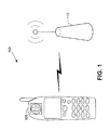
- FIG. 1 is a diagram of an electronic device 105 that is configured to transmit and/or receive wireless signals with a wireless station 110 using an antenna in accordance with some embodiments of the present invention.
- the electronic device 105 includes an antenna that comprises a single universal coil where portions of the coil are associated with various functionality provided in an electronic device 105.
- FIG. 1 illustrates exemplary communication between an electronic device 105 and a wireless station 110, it will be understood that the present invention is not limited to such configurations, but is intended to encompass any configuration capable of carrying out the operations described herein.
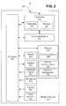
- an exemplary mobile terminal 200 that may be used to implement a device, such as the electronic device 105 of FIG. 1 , in accordance with some embodiments of the present invention, includes a video recorder 201, a camera 205, a microphone 210, a keyboard/keypad 215, a speaker 220, a display 225, a transceiver 230, and a memory 235 that communicate with a processor 240.
- the transceiver 230 comprises a transmitter circuit 245 and a receiver circuit 250, which respectively transmit outgoing radio frequency signals to base station transceivers and receive incoming radio frequency signals from the base station transceivers via an antenna 255.
- the radio frequency signals transmitted between the mobile terminal 200 and the base station transceivers may comprise both traffic and control signals (e.g., paging signals/messages for incoming calls), which are used to establish and maintain communication with another party or destination.
- the radio frequency signals may also comprise packet data information, such as, for example, cellular digital packet data (CDPD) information.
- CDPD cellular digital packet data
- the foregoing components of the mobile terminal 200 may be included in many conventional mobile terminals and their functionality is generally known to those skilled in the art.
- the mobile terminal also includes a plurality of functional modules 227 that provide various functionality and features that conventionally may be associated with a dedicated antenna or coil. According to some embodiments of the present invention, the functional modules 227 are respectively associated with portions of a universal coil that is used to implement the antenna 255.
- the processor 240 communicates with the memory 235 via an address/data bus.
- the processor 240 may be, for example, a commercially available or custom microprocessor.
- the memory 235 is representative of the one or more memory devices containing the software and data used to operate the mobile terminal 200 as well as to operate the functional modules 227 that are respectively associated with portions of the single coil comprising the antenna 255.
- the memory 235 may include, but is not limited to, the following types of devices: cache, ROM, PROM, EPROM, EEPROM, flash, SRAM, and DRAM.
- the memory 235 may contain three or more categories of software and/or data: the operating system 265, a cellular communication module 270, and/or a function management module 275.
- the operating system 265 generally controls the operation of the mobile terminal 200.
- the operating system 265 may manage the mobile terminal's software and/or hardware resources and may coordinate execution of programs by the processor 240.
- the cellular communication module 270 may be configured to manage the cellular communication protocols that are used to allow the mobile terminal 200 to communicate with other devices and systems.
- the function management module 275 may be configured to manage the various function and features provided through the functional modules 227.
- These functions/features may include, but are not limited to, a wireless charging module, a Near Field Communication (NFC) module, an Amplitude Modulation (AM) radio module, a Frequency Modulation (FM) radio module, a hearing assistance module, and a low frequencyltime code signal module.
- NFC Near Field Communication
- AM Amplitude Modulation
- FM Frequency Modulation
- hearing assistance module a low frequencyltime code signal module.
- FIG. 2 illustrates an exemplary software and hardware architecture that may be used by an electronic device, such as a mobile terminal, in which an antenna is implemented through a single universal coil comprising multiple portions associated with multiple functional modules, respectively, in accordance with some embodiments of the present invention, it will be understood that the present invention is not limited to such a configuration, but is intended to encompass any configuration capable of carrying out the operations described herein.
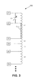
- FIG. 3 is a circuit diagram that illustrates an antenna 300 in accordance with some embodiments of the present invention.
- the antenna 300 comprises a single coil that is divided into multiple portions L1, L2, L3, and L4 using a plurality of taps.
- the different portions of the coil may be associated with the respective functional modules 227 of FIG. 2 .
- Each portion of the coil may, therefore, be tailored to implement the particular function or feature with which it is associated.
- the number of windings in a particular coil section, whether or not a core section is used to carry the windings, the type of core material used, the particular impedance Z1 - Z6 used to terminate the taps, whether a tuning capacitor C1 is used, and the like may be configured to best implement the particular function or feature.
- the tuning capacitor C1 may be referred to as a variable capacitor bank. Any tap could be connected, permanently or momentarily, to ground.
- a wireless charging module may use the entire coil and operate at a frequency of about 100kHz
- an NFC module may use a portion of the coil configured to operate at a frequency of about 13.56 MHz
- an AM radio module may use a portion of the coil configured to operate at frequencies between about 150 kHz and 1700 kHz
- an FM radio module may use a portion of the coil configured to operate at frequencies between about 76 MHz and 108 MHz
- a hearing assistance module may use the entire coil and operate at audio frequencies
- standard low frequency/time code signal module may use the entire coil and operate at a frequency about 40 kHz - 80 kHz.
- the coil could be used as an autotransformer to enhance Q while picking the signal at the number of windings where the impedance is well matched.
- the tap represented by impedance Z2 may be a variable tap where the number of windings is selected along the portion L1 and variable capacitor turning through capacitor C1 is used to fine tune the coil portion to a particular frequency.
- the multiple taps may be terminated using impedance values Z1 - Z6 to match the impedance of the particular functional module 227 with which a particular coil portion L1 - L4 is associated. This may reduce loss in communicating signals between the particular functional module 227 and the associated coil portion L1 - L4. Any one of the impedances Z1 - Z6 may be referred to as a terminating impedance.
- FIG. 4 is as block diagram that illustrates the connection between an antenna and a plurality of functional modules in accordance with some embodiments of the present invention.
- a single coil antenna 400 such as the antenna 300 of FIG. 3 , may have respective portions thereof coupled to a plurality of functional modules 410 using a switching network 425.
- the functional modules may include, but are not limited to, a wireless charging module 410A, an NFC module 410B, an AM radio module 410C, an FM radio module 410D, a hearing assistance module 410E, and a standard low frequency/time code signal module 410F.
- the switching network 425 may be operable to connect only one of the functional modules 410 to its associated portion of the single coil antenna 400 at a time. In other embodiments, however, where some functional modules are sufficiently separated in operating frequency and/or power the switching network 425 may couple multiple ones of the functional modules 410 to associated portions of the single coil antenna 400 at the same time.
- Some embodiments of the present invention may provide an antenna that comprises a single coil with portions thereof associated with various functional modules that provide various features of the electronic device that require an antenna.
- a single, universal coil approach may reduce space in the electronic device, may reduce the number of components used to implement the antenna function, and may improve performance by avoiding electromagnetic interference that can result from separate antennas and coils.
Landscapes
- Engineering & Computer Science (AREA)
- Computer Networks & Wireless Communication (AREA)
- Near-Field Transmission Systems (AREA)
Abstract
An antenna 300 used for receiving signals for a plurality of functional modules in an electronic devices includes a single coil including a first portion L1 associated with a first one of the functional modules and a second portion L2 associated with a second one of the functional modules.
Description
- The present invention relates to antennas and, more particular, to antennas used in electronic devices, such as mobile terminals.
- Electronic devices, such as mobile terminal, are made with increasingly smaller dimensions. Moreover, the functionality provided by such devices is generally increasing over time. Many of the functions and features typically use a dedicated antenna or interface coil. The existence of multiple antennas or coils in a device, however, can consume a significant amount of space, which is often in short supply in newer devices. Moreover, the multiple antennas or coils may create performance issues in a device due to electromagnetic interference or other coexistence problems.
- According to some embodiments of the present invention an antenna used for receiving signals for a plurality of functional modules in an electronic devices comprises a single coil comprising a first portion associated with a first one of the functional modules and a second portion associated with a second one of the functional modules.
- In other embodiments, the first portion of the single coil comprises a plurality of taps.
- In still other embodiments, the first portion of the single coil is disposed around a core material.
- In still other embodiments, the antenna further comprises a first terminating impedance coupled to the first portion of the single coil that is associated with the first one of the functional modules and a second terminating impedance coupled to the second portion of the single coil that is associated with the second one of the functional modules.
- In still other embodiments, the antenna further comprises a variable capacitor bank coupled to the single coil.
- In still other embodiments, the first one of the functional modules comprises a wireless charging functional module.
- In still other embodiments, the first one of the functional modules comprises a Near Field Communication (NFC) functional module.
- In still other embodiments, the first one of the functional modules comprises an Amplitude Modulation (AM) radio functional module.
- In still other embodiments, the first one of the functional modules comprises a Frequency Modulation (FM) radio functional module.
- In still other embodiments, the first one of the functional modules comprises a hearing assistance functional module.
- In still other embodiments, the first one of the functional modules comprises a standard low frequency and time code signal functional module.
- In further embodiments of the present invention, an electronic device comprises a plurality of functional modules, a single coil comprising a plurality of portions associated with respective ones of the plurality of functional modules, and a switching network that is operable to connect the plurality of functional modules to the plurality of portions of the single coil, respectively.
- In still further embodiments, the electronic device further comprises a variable capacitor bank coupled to the single coil.
- In still further embodiments, one of the plurality of functional modules comprises a wireless charging functional module.
- In still further embodiments, one of the plurality of functional modules comprises a Near Field Communication (NFC) functional module.
- In still further embodiments, one of the plurality of functional modules comprises an Amplitude Modulation (AM) radio functional module.
- In still further embodiments, one of the plurality of functional modules comprises a Frequency Modulation (FM) radio functional module.
- In still further embodiments, one of the plurality of functional modules comprises a hearing assistance functional module.
- In still further embodiments, one of the plurality of functional modules comprises a standard low frequency and time code signal functional module.
- In still further embodiments, the electronic device is a mobile terminal.
- Other features of the present invention will be more readily understood from the following detailed description of specific embodiments thereof when read in conjunction with the accompanying drawings, in which:
-
FIG. 1 is a diagram of an electronic device that is configured to transmit and/or receive wireless signals with a wireless station using an antenna in accordance with some embodiments of the present invention; -
FIG. 2 is a block diagram that illustrates an electronic device/mobile terminal in accordance with some embodiments of the present invention; -
FIG. 3 is a circuit diagram that illustrates an antenna in accordance with some embodiments of the present invention; and -
FIG. 4 is as block diagram that illustrates the connection between an antenna and a plurality of functional modules in accordance with some embodiments of the present invention. - While the invention is susceptible to various modifications and alternative forms, specific embodiments thereof are shown by way of example in the drawings and will herein be described in detail. It should be understood, however, that there is no intent to limit the invention to the particular forms disclosed, but on the contrary, the invention is to cover all modifications, equivalents, and alternatives falling within the spirit and scope of the invention as defined by the claims. Like reference numbers signify like elements throughout the description of the figures.
- As used herein, the singular forms "a," "an," and "the" are intended to include the plural forms as well, unless expressly stated otherwise. It should be further understood that the terms "comprises" and/or "comprising" when used in this specification is taken to specify the presence of stated features, integers, steps, operations, elements, and/or components, but does not preclude the presence or addition of one or more other features, integers, steps, operations, elements, components, and/or groups thereof. It will be understood that when an element is referred to as being "connected" or "coupled" to another element, it can be directly connected or coupled to the other element or intervening elements may be present. Furthermore, "connected" or "coupled" as used herein may include wirelessly connected or coupled. As used herein, the term "and/or" includes any and all combinations of one or more of the associated listed items.
- Unless otherwise defined, all terms (including technical and scientific terms) used herein have the same meaning as commonly understood by one of ordinary skill in the art to which this invention belongs. It will be further understood that terms, such as those defined in commonly used dictionaries, should be interpreted as having a meaning that is consistent with their meaning in the context of the relevant art and this specification and will not be interpreted in an idealized or overly formal sense unless expressly so defined herein.
- As used herein, the term "mobile terminal" may include a satellite or cellular radiotelephone with or without a multi-line display; a Personal Communications System (PCS) terminal that may combine a cellular radiotelephone with data processing, facsimile and data communications capabilities; a PDA that can include a radiotelephone, pager, Intemet/intranet access, Web browser, organizer, calendar and/or a global positioning system (GPS) receiver; and a conventional laptop and/or palmtop receiver or other appliance that includes a radiotelephone transceiver. Mobile terminals may also be referred to as "pervasive computing" devices.
- For purposes of illustration, embodiments of the present invention are described herein in the context of a mobile terminal. It will be understood, however, that the present invention is not limited to such embodiments and may be embodied generally as an electronic device that is configured to establish connections with one or more peripheral devices or accessories.
- Some embodiments of the present invention arise from a realization that if many of the functions in an electronic device, such as a mobile terminal, are assigned their own antenna or coil, then valuable space inside the device could be taken up with the multiple antennas or coils and/or the multiple antennas or coils could create performance problems for a device due to electromagnetic interference or other coexistence issues. Some embodiments of the present invention provide an antenna that comprises a single universal coil where portions of the coil are associated with various functionality provided in an electronic device. Such a design may save space, reduce component count, and/or reduce coexistence issues that may be seen with separate antennas dedicated to individual functions.
-
FIG. 1 is a diagram of anelectronic device 105 that is configured to transmit and/or receive wireless signals with awireless station 110 using an antenna in accordance with some embodiments of the present invention. Theelectronic device 105 includes an antenna that comprises a single universal coil where portions of the coil are associated with various functionality provided in anelectronic device 105. - Although
FIG. 1 illustrates exemplary communication between anelectronic device 105 and awireless station 110, it will be understood that the present invention is not limited to such configurations, but is intended to encompass any configuration capable of carrying out the operations described herein. - Referring now to
FIG. 2 , an exemplarymobile terminal 200 that may be used to implement a device, such as theelectronic device 105 ofFIG. 1 , in accordance with some embodiments of the present invention, includes avideo recorder 201, acamera 205, amicrophone 210, a keyboard/keypad 215, aspeaker 220, adisplay 225, atransceiver 230, and amemory 235 that communicate with aprocessor 240. Thetransceiver 230 comprises atransmitter circuit 245 and areceiver circuit 250, which respectively transmit outgoing radio frequency signals to base station transceivers and receive incoming radio frequency signals from the base station transceivers via anantenna 255. The radio frequency signals transmitted between themobile terminal 200 and the base station transceivers may comprise both traffic and control signals (e.g., paging signals/messages for incoming calls), which are used to establish and maintain communication with another party or destination. The radio frequency signals may also comprise packet data information, such as, for example, cellular digital packet data (CDPD) information. - The foregoing components of the
mobile terminal 200 may be included in many conventional mobile terminals and their functionality is generally known to those skilled in the art. - The mobile terminal also includes a plurality of
functional modules 227 that provide various functionality and features that conventionally may be associated with a dedicated antenna or coil. According to some embodiments of the present invention, thefunctional modules 227 are respectively associated with portions of a universal coil that is used to implement theantenna 255. - The
processor 240 communicates with thememory 235 via an address/data bus. Theprocessor 240 may be, for example, a commercially available or custom microprocessor. Thememory 235 is representative of the one or more memory devices containing the software and data used to operate themobile terminal 200 as well as to operate thefunctional modules 227 that are respectively associated with portions of the single coil comprising theantenna 255. Thememory 235 may include, but is not limited to, the following types of devices: cache, ROM, PROM, EPROM, EEPROM, flash, SRAM, and DRAM. - As shown in
FIG. 2 , thememory 235 may contain three or more categories of software and/or data: theoperating system 265, acellular communication module 270, and/or afunction management module 275. Theoperating system 265 generally controls the operation of themobile terminal 200. In particular, theoperating system 265 may manage the mobile terminal's software and/or hardware resources and may coordinate execution of programs by theprocessor 240. Thecellular communication module 270 may be configured to manage the cellular communication protocols that are used to allow themobile terminal 200 to communicate with other devices and systems. Thefunction management module 275 may be configured to manage the various function and features provided through thefunctional modules 227. These functions/features may include, but are not limited to, a wireless charging module, a Near Field Communication (NFC) module, an Amplitude Modulation (AM) radio module, a Frequency Modulation (FM) radio module, a hearing assistance module, and a low frequencyltime code signal module. - Although
FIG. 2 illustrates an exemplary software and hardware architecture that may be used by an electronic device, such as a mobile terminal, in which an antenna is implemented through a single universal coil comprising multiple portions associated with multiple functional modules, respectively, in accordance with some embodiments of the present invention, it will be understood that the present invention is not limited to such a configuration, but is intended to encompass any configuration capable of carrying out the operations described herein. -
FIG. 3 is a circuit diagram that illustrates anantenna 300 in accordance with some embodiments of the present invention. As shown inFIG. 3 , theantenna 300 comprises a single coil that is divided into multiple portions L1, L2, L3, and L4 using a plurality of taps. The different portions of the coil may be associated with the respectivefunctional modules 227 ofFIG. 2 . Each portion of the coil may, therefore, be tailored to implement the particular function or feature with which it is associated. For example, the number of windings in a particular coil section, whether or not a core section is used to carry the windings, the type of core material used, the particular impedance Z1 - Z6 used to terminate the taps, whether a tuning capacitor C1 is used, and the like may be configured to best implement the particular function or feature. The tuning capacitor C1 may be referred to as a variable capacitor bank. Any tap could be connected, permanently or momentarily, to ground. - In some embodiments, a wireless charging module may use the entire coil and operate at a frequency of about 100kHz, an NFC module may use a portion of the coil configured to operate at a frequency of about 13.56 MHz, an AM radio module may use a portion of the coil configured to operate at frequencies between about 150 kHz and 1700 kHz, an FM radio module may use a portion of the coil configured to operate at frequencies between about 76 MHz and 108 MHz, a hearing assistance module may use the entire coil and operate at audio frequencies, and standard low frequency/time code signal module may use the entire coil and operate at a frequency about 40 kHz - 80 kHz.
- In general for functions or features using higher frequencies and requiring a higher Quality (Q) factor, only a part of the coil with suitable inductance for high Q tuning is used. In some embodiments, the coil could be used as an autotransformer to enhance Q while picking the signal at the number of windings where the impedance is well matched. In the example shown in
FIG. 3 , the tap represented by impedance Z2 may be a variable tap where the number of windings is selected along the portion L1 and variable capacitor turning through capacitor C1 is used to fine tune the coil portion to a particular frequency. The multiple taps may be terminated using impedance values Z1 - Z6 to match the impedance of the particularfunctional module 227 with which a particular coil portion L1 - L4 is associated. This may reduce loss in communicating signals between the particularfunctional module 227 and the associated coil portion L1 - L4. Any one of the impedances Z1 - Z6 may be referred to as a terminating impedance. -
FIG. 4 is as block diagram that illustrates the connection between an antenna and a plurality of functional modules in accordance with some embodiments of the present invention. Asingle coil antenna 400, such as theantenna 300 ofFIG. 3 , may have respective portions thereof coupled to a plurality of functional modules 410 using aswitching network 425. The functional modules may include, but are not limited to, awireless charging module 410A, anNFC module 410B, anAM radio module 410C, anFM radio module 410D, ahearing assistance module 410E, and a standard low frequency/timecode signal module 410F. In accordance with various embodiments of the present invention, theswitching network 425 may be operable to connect only one of the functional modules 410 to its associated portion of thesingle coil antenna 400 at a time. In other embodiments, however, where some functional modules are sufficiently separated in operating frequency and/or power theswitching network 425 may couple multiple ones of the functional modules 410 to associated portions of thesingle coil antenna 400 at the same time. - Some embodiments of the present invention may provide an antenna that comprises a single coil with portions thereof associated with various functional modules that provide various features of the electronic device that require an antenna. In contrast with conventional approaches where a dedicated antenna or coil is provided to each functional module, a single, universal coil approach may reduce space in the electronic device, may reduce the number of components used to implement the antenna function, and may improve performance by avoiding electromagnetic interference that can result from separate antennas and coils.
- Many variations and modifications can be made to the embodiments without substantially departing from the principles of the present invention. All such variations and modifications are intended to be included herein within the scope of the present invention, as set forth in the following claims.
Claims (14)
- An antenna (255; 300; 400) for receiving signals for a plurality of functional modules (227) in an electronic device (105; 220), comprising:a single coil comprising a first portion (L1; L2; L3; L4) associated with a first one of the functional modules (227) and a second portion (L1; L2; L3; L4) associated with a second one of the functional modules (227).
- The antenna (255; 300; 400) of Claim 1, wherein the first portion (L1) of the single coil comprises a plurality of taps.
- The antenna (255; 300; 400) of Claim 1 or 2, wherein the first portion (L1) of the single coil is disposed around a core material.
- The antenna (255; 300; 400) of any one of the preceding Claims, further comprising:a first terminating impedance (Z1, Z2, Z3) coupled to the first portion (L1) of the single coil that is associated with the first one of the functional modules (227); anda second terminating impedance (Z3, Z4) coupled to the second portion (L2) of the single coil that is associated with the second one of the functional modules (227).
- The antenna (255; 300; 400) of any one of the preceding Claims, further comprising:a variable capacitor bank (C1) coupled to the single coil.
- The antenna (255; 300; 400) of any one of the preceding Claims, wherein the first one of the functional modules (227) comprises a wireless charging functional module (410A).
- The antenna (255; 300; 400) of any one of Claims 1 - 5, wherein the first one of the functional modules (227) comprises a Near Field Communication (NFC) functional module (410B).
- The antenna (255; 300; 400) of any one of Claims 1 - 5, wherein the first one of the functional modules (227) comprises an Amplitude Modulation (AM) radio functional module (410C).
- The antenna (255; 300; 400) of any one of Claims 1 - 5, wherein the first one of the functional modules (227) comprises a Frequency Modulation (FM) radio functional module (410D).
- The antenna (255; 300; 400) of any one of Claims 1 - 5, wherein the first one of the functional modules (227) comprises a hearing assistance functional module (41 OF).
- The antenna (255; 300; 400) of any one of Claims 1 - 5, wherein the first one of the functional modules (227) comprises a standard low frequency and time code signal functional module (410F).
- An electronic device (105), comprising:a plurality of functional modules (227);a single coil comprising a plurality of portions (L1 - L4) associated with respective ones of the plurality of functional modules (227); anda switching network (425) that is operable to connect the plurality of functional modules (227) to the plurality of portions of the single coil, respectively.
- The electronic device (105) of Claim 12, wherein the single coil is comprised in an antenna (255; 300; 400) according to any one of claims 1 - 11.
- The electronic device (105) of Claim 12 or 13, wherein the electronic device is a mobile terminal (200).
Applications Claiming Priority (1)
| Application Number | Priority Date | Filing Date | Title |
|---|---|---|---|
| US13/237,475 US20130072254A1 (en) | 2011-09-20 | 2011-09-20 | Universal Coil Antenna Having Respective Portions Thereof Associated with Different Functional Modules |
Publications (1)
| Publication Number | Publication Date |
|---|---|
| EP2573866A1 true EP2573866A1 (en) | 2013-03-27 |
Family
ID=46982359
Family Applications (1)
| Application Number | Title | Priority Date | Filing Date |
|---|---|---|---|
| EP12177065A Withdrawn EP2573866A1 (en) | 2011-09-20 | 2012-07-19 | Universal coil antenna having respective portions thereof associated with different functional modules |
Country Status (2)
| Country | Link |
|---|---|
| US (1) | US20130072254A1 (en) |
| EP (1) | EP2573866A1 (en) |
Cited By (2)
| Publication number | Priority date | Publication date | Assignee | Title |
|---|---|---|---|---|
| RU2604655C1 (en) * | 2013-06-09 | 2016-12-10 | Сяоми Инк. | Multifunctional circuit with multiturn coil, and method and device for control of multifunctional circuit with multi-turn coil |
| WO2017008384A1 (en) * | 2015-07-16 | 2017-01-19 | 中兴通讯股份有限公司 | Antenna structure and mobile terminal |
Families Citing this family (8)
| Publication number | Priority date | Publication date | Assignee | Title |
|---|---|---|---|---|
| US20140349572A1 (en) * | 2008-09-23 | 2014-11-27 | Powermat Technologies Ltd. | Integrated inductive power receiver and near field communicator |
| CN108111417B (en) * | 2013-08-15 | 2022-12-27 | 华为技术有限公司 | Method and device for forwarding MPLS data packet |
| KR101594380B1 (en) | 2015-03-04 | 2016-02-16 | 엘지전자 주식회사 | Mobile terminal and coil antenna moduel |
| US10412752B2 (en) * | 2016-07-26 | 2019-09-10 | Qualcomm Incorporated | Coexistence management of GNSS and wireless operations |
| KR20190065520A (en) * | 2017-12-02 | 2019-06-12 | 현대자동차주식회사 | Antenna apparatus and vehicle comprising the antenna apparatus |
| CN115206646A (en) * | 2021-04-12 | 2022-10-18 | 北京小米移动软件有限公司 | Coil mechanism and terminal equipment |
| CN113992235A (en) * | 2021-10-27 | 2022-01-28 | 维沃移动通信有限公司 | Antenna control method and related equipment |
| CN113992244A (en) * | 2021-10-27 | 2022-01-28 | 维沃移动通信有限公司 | Electronic apparatus and control method |
Citations (3)
| Publication number | Priority date | Publication date | Assignee | Title |
|---|---|---|---|---|
| GB2414083A (en) * | 2004-05-10 | 2005-11-16 | Risco Group Uk Ltd | Proximity sensor system |
| US20100123561A1 (en) * | 2008-11-19 | 2010-05-20 | Samsung Electronics Co., Ltd. | Radio frequency identification apparatus with a plurality of radio frequency identification schemes |
| US20100279734A1 (en) * | 2009-04-30 | 2010-11-04 | Nokia Corporation | Multiprotocol Antenna For Wireless Systems |
Family Cites Families (3)
| Publication number | Priority date | Publication date | Assignee | Title |
|---|---|---|---|---|
| EP2026406A1 (en) * | 2007-08-14 | 2009-02-18 | Oticon A/S | Multipurpose antenna unit |
| US8855353B2 (en) * | 2007-12-20 | 2014-10-07 | Nxp, B.V. | Headset loop antenna for audio devices |
| WO2010019961A2 (en) * | 2008-08-15 | 2010-02-18 | Ivi Smart Technologies, Inc. | Rf power conversion circuits & methods, both for use in mobile devices |
-
2011
- 2011-09-20 US US13/237,475 patent/US20130072254A1/en not_active Abandoned
-
2012
- 2012-07-19 EP EP12177065A patent/EP2573866A1/en not_active Withdrawn
Patent Citations (3)
| Publication number | Priority date | Publication date | Assignee | Title |
|---|---|---|---|---|
| GB2414083A (en) * | 2004-05-10 | 2005-11-16 | Risco Group Uk Ltd | Proximity sensor system |
| US20100123561A1 (en) * | 2008-11-19 | 2010-05-20 | Samsung Electronics Co., Ltd. | Radio frequency identification apparatus with a plurality of radio frequency identification schemes |
| US20100279734A1 (en) * | 2009-04-30 | 2010-11-04 | Nokia Corporation | Multiprotocol Antenna For Wireless Systems |
Cited By (3)
| Publication number | Priority date | Publication date | Assignee | Title |
|---|---|---|---|---|
| RU2604655C1 (en) * | 2013-06-09 | 2016-12-10 | Сяоми Инк. | Multifunctional circuit with multiturn coil, and method and device for control of multifunctional circuit with multi-turn coil |
| US9930239B2 (en) | 2013-06-09 | 2018-03-27 | Xiaomi Inc. | Multi-turn coil multiplex circuit and method and device for controlling multi-turn coil multiplex circuit |
| WO2017008384A1 (en) * | 2015-07-16 | 2017-01-19 | 中兴通讯股份有限公司 | Antenna structure and mobile terminal |
Also Published As
| Publication number | Publication date |
|---|---|
| US20130072254A1 (en) | 2013-03-21 |
Similar Documents
| Publication | Publication Date | Title |
|---|---|---|
| US20130072254A1 (en) | Universal Coil Antenna Having Respective Portions Thereof Associated with Different Functional Modules | |
| US9484977B2 (en) | RF transformer based TX/RX integrated RF switch | |
| US8405568B2 (en) | Wireless communication device antenna with tuning elements | |
| US6816711B2 (en) | GPS equipped mobile phone with single shared antenna | |
| US8232925B2 (en) | Impedance tuning of transmitting and receiving antennas | |
| EP2092656B1 (en) | Wireless communications circuitry with simultaneous receive capabilities for handheld electronic devices | |
| CN102158236A (en) | Near field communication (NFC) dual-mode mobile terminal and communication method thereof | |
| US20020037741A1 (en) | Wireless systems internet gateway | |
| CN115004560B (en) | Impedance Matching Transceiver | |
| EP2130303A1 (en) | Multiple impedance matching networks for multiband transceivers | |
| GB2459919A (en) | Combined communication and direction-finding apparatus | |
| EP3178168A1 (en) | Front end architecture for intermittent emissions and/or coexistence specifications | |
| US20130252562A1 (en) | High power high isolation low current cmos rf switch | |
| GB2395635A (en) | Accessing alternate wide area and local area wireless networks transitioning between them and between more than one local area network | |
| CN105490004A (en) | Mobile terminal antenna system and mobile terminal | |
| US20160126640A1 (en) | Diversity antenna apparatus of mobile terminal and implementation method thereof | |
| CN115241642B (en) | Multi-frequency broadband self-decoupling terminal antenna and electronic equipment | |
| US20130194136A1 (en) | Mobile wireless communications device with multiple-band antenna and related methods | |
| EP3002821A1 (en) | Wireless communication terminal | |
| CN218275054U (en) | A satellite antenna transceiver module and mobile terminal | |
| US20140210685A1 (en) | Electronic device and antenna control method thereof | |
| WO2017142555A1 (en) | Separate antennae | |
| US10411326B1 (en) | Single feed passive antenna for a metal back cover | |
| CN109688521B (en) | A speaker, preparation method, wireless communication module and terminal device | |
| JP2003309489A (en) | Portable radio equipment |
Legal Events
| Date | Code | Title | Description |
|---|---|---|---|
| PUAI | Public reference made under article 153(3) epc to a published international application that has entered the european phase |
Free format text: ORIGINAL CODE: 0009012 |
|
| 17P | Request for examination filed |
Effective date: 20120719 |
|
| AK | Designated contracting states |
Kind code of ref document: A1 Designated state(s): AL AT BE BG CH CY CZ DE DK EE ES FI FR GB GR HR HU IE IS IT LI LT LU LV MC MK MT NL NO PL PT RO RS SE SI SK SM TR |
|
| AX | Request for extension of the european patent |
Extension state: BA ME |
|
| STAA | Information on the status of an ep patent application or granted ep patent |
Free format text: STATUS: THE APPLICATION IS DEEMED TO BE WITHDRAWN |
|
| 18D | Application deemed to be withdrawn |
Effective date: 20130928 |