EP2573840A1 - Coating apparatus - Google Patents
Coating apparatus Download PDFInfo
- Publication number
- EP2573840A1 EP2573840A1 EP11783490A EP11783490A EP2573840A1 EP 2573840 A1 EP2573840 A1 EP 2573840A1 EP 11783490 A EP11783490 A EP 11783490A EP 11783490 A EP11783490 A EP 11783490A EP 2573840 A1 EP2573840 A1 EP 2573840A1
- Authority
- EP
- European Patent Office
- Prior art keywords
- electrode material
- kneaded
- temperature
- coating
- storage modulus
- Prior art date
- Legal status (The legal status is an assumption and is not a legal conclusion. Google has not performed a legal analysis and makes no representation as to the accuracy of the status listed.)
- Withdrawn
Links
Images

Classifications
-
- H—ELECTRICITY
- H01—ELECTRIC ELEMENTS
- H01M—PROCESSES OR MEANS, e.g. BATTERIES, FOR THE DIRECT CONVERSION OF CHEMICAL ENERGY INTO ELECTRICAL ENERGY
- H01M4/00—Electrodes
- H01M4/02—Electrodes composed of, or comprising, active material
- H01M4/04—Processes of manufacture in general
- H01M4/0402—Methods of deposition of the material
- H01M4/0404—Methods of deposition of the material by coating on electrode collectors
-
- B—PERFORMING OPERATIONS; TRANSPORTING
- B05—SPRAYING OR ATOMISING IN GENERAL; APPLYING FLUENT MATERIALS TO SURFACES, IN GENERAL
- B05C—APPARATUS FOR APPLYING FLUENT MATERIALS TO SURFACES, IN GENERAL
- B05C11/00—Component parts, details or accessories not specifically provided for in groups B05C1/00 - B05C9/00
- B05C11/10—Storage, supply or control of liquid or other fluent material; Recovery of excess liquid or other fluent material
-
- B—PERFORMING OPERATIONS; TRANSPORTING
- B05—SPRAYING OR ATOMISING IN GENERAL; APPLYING FLUENT MATERIALS TO SURFACES, IN GENERAL
- B05C—APPARATUS FOR APPLYING FLUENT MATERIALS TO SURFACES, IN GENERAL
- B05C11/00—Component parts, details or accessories not specifically provided for in groups B05C1/00 - B05C9/00
- B05C11/10—Storage, supply or control of liquid or other fluent material; Recovery of excess liquid or other fluent material
- B05C11/1042—Storage, supply or control of liquid or other fluent material; Recovery of excess liquid or other fluent material provided with means for heating or cooling the liquid or other fluent material in the supplying means upstream of the applying apparatus
-
- B—PERFORMING OPERATIONS; TRANSPORTING
- B05—SPRAYING OR ATOMISING IN GENERAL; APPLYING FLUENT MATERIALS TO SURFACES, IN GENERAL
- B05C—APPARATUS FOR APPLYING FLUENT MATERIALS TO SURFACES, IN GENERAL
- B05C5/00—Apparatus in which liquid or other fluent material is projected, poured or allowed to flow on to the surface of the work
- B05C5/02—Apparatus in which liquid or other fluent material is projected, poured or allowed to flow on to the surface of the work the liquid or other fluent material being discharged through an outlet orifice by pressure, e.g. from an outlet device in contact or almost in contact, with the work
-
- B—PERFORMING OPERATIONS; TRANSPORTING
- B05—SPRAYING OR ATOMISING IN GENERAL; APPLYING FLUENT MATERIALS TO SURFACES, IN GENERAL
- B05C—APPARATUS FOR APPLYING FLUENT MATERIALS TO SURFACES, IN GENERAL
- B05C5/00—Apparatus in which liquid or other fluent material is projected, poured or allowed to flow on to the surface of the work
- B05C5/02—Apparatus in which liquid or other fluent material is projected, poured or allowed to flow on to the surface of the work the liquid or other fluent material being discharged through an outlet orifice by pressure, e.g. from an outlet device in contact or almost in contact, with the work
- B05C5/0254—Coating heads with slot-shaped outlet
-
- H—ELECTRICITY
- H01—ELECTRIC ELEMENTS
- H01M—PROCESSES OR MEANS, e.g. BATTERIES, FOR THE DIRECT CONVERSION OF CHEMICAL ENERGY INTO ELECTRICAL ENERGY
- H01M4/00—Electrodes
- H01M4/02—Electrodes composed of, or comprising, active material
- H01M4/04—Processes of manufacture in general
- H01M4/0402—Methods of deposition of the material
- H01M4/0411—Methods of deposition of the material by extrusion
-
- H—ELECTRICITY
- H01—ELECTRIC ELEMENTS
- H01M—PROCESSES OR MEANS, e.g. BATTERIES, FOR THE DIRECT CONVERSION OF CHEMICAL ENERGY INTO ELECTRICAL ENERGY
- H01M4/00—Electrodes
- H01M4/02—Electrodes composed of, or comprising, active material
- H01M4/13—Electrodes for accumulators with non-aqueous electrolyte, e.g. for lithium-accumulators; Processes of manufacture thereof
- H01M4/139—Processes of manufacture
-
- H—ELECTRICITY
- H01—ELECTRIC ELEMENTS
- H01M—PROCESSES OR MEANS, e.g. BATTERIES, FOR THE DIRECT CONVERSION OF CHEMICAL ENERGY INTO ELECTRICAL ENERGY
- H01M10/00—Secondary cells; Manufacture thereof
- H01M10/04—Construction or manufacture in general
- H01M2010/0495—Nanobatteries
-
- Y—GENERAL TAGGING OF NEW TECHNOLOGICAL DEVELOPMENTS; GENERAL TAGGING OF CROSS-SECTIONAL TECHNOLOGIES SPANNING OVER SEVERAL SECTIONS OF THE IPC; TECHNICAL SUBJECTS COVERED BY FORMER USPC CROSS-REFERENCE ART COLLECTIONS [XRACs] AND DIGESTS
- Y02—TECHNOLOGIES OR APPLICATIONS FOR MITIGATION OR ADAPTATION AGAINST CLIMATE CHANGE
- Y02E—REDUCTION OF GREENHOUSE GAS [GHG] EMISSIONS, RELATED TO ENERGY GENERATION, TRANSMISSION OR DISTRIBUTION
- Y02E60/00—Enabling technologies; Technologies with a potential or indirect contribution to GHG emissions mitigation
- Y02E60/10—Energy storage using batteries
-
- Y—GENERAL TAGGING OF NEW TECHNOLOGICAL DEVELOPMENTS; GENERAL TAGGING OF CROSS-SECTIONAL TECHNOLOGIES SPANNING OVER SEVERAL SECTIONS OF THE IPC; TECHNICAL SUBJECTS COVERED BY FORMER USPC CROSS-REFERENCE ART COLLECTIONS [XRACs] AND DIGESTS
- Y02—TECHNOLOGIES OR APPLICATIONS FOR MITIGATION OR ADAPTATION AGAINST CLIMATE CHANGE
- Y02P—CLIMATE CHANGE MITIGATION TECHNOLOGIES IN THE PRODUCTION OR PROCESSING OF GOODS
- Y02P70/00—Climate change mitigation technologies in the production process for final industrial or consumer products
- Y02P70/50—Manufacturing or production processes characterised by the final manufactured product
-
- Y—GENERAL TAGGING OF NEW TECHNOLOGICAL DEVELOPMENTS; GENERAL TAGGING OF CROSS-SECTIONAL TECHNOLOGIES SPANNING OVER SEVERAL SECTIONS OF THE IPC; TECHNICAL SUBJECTS COVERED BY FORMER USPC CROSS-REFERENCE ART COLLECTIONS [XRACs] AND DIGESTS
- Y10—TECHNICAL SUBJECTS COVERED BY FORMER USPC
- Y10T—TECHNICAL SUBJECTS COVERED BY FORMER US CLASSIFICATION
- Y10T137/00—Fluid handling
- Y10T137/6416—With heating or cooling of the system
- Y10T137/6579—Circulating fluid in heat exchange relationship
-
- Y—GENERAL TAGGING OF NEW TECHNOLOGICAL DEVELOPMENTS; GENERAL TAGGING OF CROSS-SECTIONAL TECHNOLOGIES SPANNING OVER SEVERAL SECTIONS OF THE IPC; TECHNICAL SUBJECTS COVERED BY FORMER USPC CROSS-REFERENCE ART COLLECTIONS [XRACs] AND DIGESTS
- Y10—TECHNICAL SUBJECTS COVERED BY FORMER USPC
- Y10T—TECHNICAL SUBJECTS COVERED BY FORMER US CLASSIFICATION
- Y10T137/00—Fluid handling
- Y10T137/8593—Systems
- Y10T137/85978—With pump
- Y10T137/86035—Combined with fluid receiver
Definitions
- This invention relates to a coating apparatus.
- JP2007-66744A discloses a coating apparatus which suppresses a variation of a coating amount and performs stable coating by adjusting a pressure in applying a coating material.
- the kneaded electrode material in the case of applying a slurry-like kneaded electrode material prepared by kneading an electrode material and a solvent, the kneaded electrode material has received heat from coating apparatus components such as a pump. This causes unstable properties due to a temperature variation of the kneaded electrode material until a specified time elapses after the start of coating, whereby the coating amount varies and stable coating cannot be performed. Thus, there has been a problem of requiring time until the coating amount becomes constant from the start of coating.
- the present invention was developed in view of such a problem and an object thereof is to shorten a time required until a coating amount becomes constant after the start of coating.
- the present invention includes a coating unit for applying a slurry-like kneaded electrode material prepared by kneading an electrode material and a solvent, a pump for feeding the kneaded electrode material under pressure to the coating unit, and a temperature raising unit for raising the temperature of the electrode material before coating to a predetermined temperature range where a storage modulus of the kneaded electrode material becomes substantially constant.
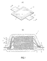
- FIGS. 1 are schematic views of a lithium-ion secondary battery 1.
- FIG. 1(A) is a perspective view of the lithium-ion secondary battery 1 and
- FIG. 1(B) is a sectional view along B-B of FIG. 1(A) .
- the lithium-ion secondary battery 1 includes a storage element 2 and an exterior case 3 for housing the storage element 2.
- the storage element 2 is formed as a laminated body in which positive electrodes 4, separators 5 as electrolyte layers and negative electrodes 6 are successively laminated.
- the positive electrode 4 includes positive electrode layers 4b on opposite surfaces of a plate-like positive electrode current collector 4a
- the negative electrode 6 includes negative electrode layers 6b on opposite surfaces of a plate-like negative electrode current collector 6a. Note that, for the positive electrode 4 arranged in the outermost layer of the storage element 2, the positive electrode layer 4b is formed only on one surface of the positive electrode current collector 4a.
- the adjacent positive electrode 4, separator 5 and negative electrode 6 form one unit cell 7, and the lithium-ion battery 1 is formed by electrically connecting a plurality of laminated unit cells 7 in parallel.
- the exterior case 3 is made of a polymer-metal complex laminated film sheet material in which a metal such as aluminum is covered with an insulator such as a polypropylene film. Outer peripheral parts of the exterior case 3 are joined by thermal fusion with the storage element 2 housed in the exterior case 3.
- This exterior case 3 is provided with a positive electrode tab 8 and a negative electrode tab 9 as external terminals to take out power from the storage element 2 to the outside.
- One end of the positive electrode tab 8 is located outside the exterior case 3 and the other end of the positive electrode tab 8 is connected to an aggregate of each positive electrode current collector 4a inside the exterior case 3.
- One end of the negative electrode tab 9 is located outside the exterior case 3 and the other end of the negative electrode tab 9 is connected to an aggregate of each negative electrode current collector 6a inside the exterior case 3.
- an electrode is manufactured by way of a coating process of applying a slurry-like kneaded electrode material prepared by kneading an electrode material and a solvent to a current collector (positive electrode current collector 4a or negative electrode current collector 6a) and then a drying process of volatizing the solvent of the kneaded electrode material to form an electrode layer (positive-electrode layer 4b or negative electrode layer 6b) which is 100 % of solid content.
- a time required for the coating process is shortened by suppressing a temperature variation of the kneaded electrode material in the coating process and making a coating amount stable in an early stage.
- FIG. 2 is a schematic configuration diagram of the electrode manufacturing apparatus 100 according to this embodiment used at the time of manufacturing the electrodes of the lithium-ion secondary battery 1.
- the electrode manufacturing apparatus 100 includes a conveying apparatus 10, a kneading apparatus 20, a coating apparatus 30, a drying apparatus 40 and a controller 50.
- the electrode manufacturing apparatus 100 is an apparatus for manufacturing an electrode by applying a kneaded electrode material 21 kneaded by the kneading apparatus 20 to a surface of a metal foil 14 conveyed by the conveying apparatus 10 by the coating apparatus 30 and drying the kneaded electrode material 21 by the drying apparatus 40. If necessary, the electrode may be pressed by a press apparatus after drying to adjust the thickness and the like.
- Each apparatus constituting the electrode manufacturing apparatus 100 is described in detail below.
- the conveying apparatus 10 includes an unwind roll 11, a take-up roll 12, and support rolls 13.
- the conveying apparatus 10 conveys a metal foil (having a thickness of 10 [ ⁇ m] to 40 [ ⁇ m]) 14 in the form of a thin film, which becomes the positive electrode current collector 4a or the negative electrode current collector 6a, from the unwind roll 11 to the take-up roll 12 by a roll-to-roll method.
- an aluminum foil is used as the metal foil 14 that becomes the positive electrode current collector 4a in the case of manufacturing the positive electrode 4 and a copper foil is used as the metal foil 14 that becomes the negative electrode current collector 6a in the case of manufacturing the negative electrode 6.
- a copper foil is used as the metal foil 14 that becomes the negative electrode current collector 6a in the case of manufacturing the negative electrode 6.
- the metal foil 14 is wound on the unwind roll 11.
- the unwind roll 11 includes a braking mechanism 15, and the rotation of the unwind roll 11 is appropriately restricted by this braking mechanism 15 to apply a predetermined tension to the metal foil 14.
- the take-up roll 12 is driven and rotated by a drive motor 16 and takes up the metal foil 14 pulled from the unwind roll 11.
- a plurality of support rolls 13 are provided in a metal foil conveyance path between the unwind roll 11 and the take-up roll 12 and hold the lower surface of the metal foil 14 being conveyed.
- the kneading apparatus 20 is a twin screw kneader and produces the slurry-like kneaded electrode material 21 by uniformly dispersing the electrode material in the solvent.
- the kneading apparatus 20 is not limited to the twin screw kneader and, for example, a planetary mixer or kneader may be used.
- the kneaded electrode material 21 includes a kneaded positive electrode material produced in the case of manufacturing the positive electrode 4 and a kneaded negative electrode material produced in the case of manufacturing the negative electrode 6.
- a positive electrode active material as the electrode material, a conductive assistant and a binder are poured into the kneading apparatus 20 and these are uniformly dispersed in the solvent.
- a negative electrode active material as the electrode material, a conductive assistant and a binder are poured into the kneading apparatus 20 and these are uniformly dispersed in the solvent.
- the positive electrode active material is a material which stores and releases lithium ions of lithium metal oxides and the like.
- lithium manganate is used as the positive electrode active material.
- the negative electrode active material is a material which stores and release lithium ions of hard carbons, graphites and the like.
- hard carbon is used as the negative electrode active material.
- the conductive assistant is a substance for improving conductivity of a carbon material (carbon powder, carbon fibers) and the like.
- Various carbon blacks such as acetylene black, furnace black and Ketjen Black and graphite powder can be used as the carbon powder.
- carbon black is used as the conductive assistant both in the case of producing the kneaded positive electrode material and in the case of producing the kneaded negative electrode material.
- the binder is a substance for binding active material fine particles to each other.
- PVDF polyvinylidene fluoride
- the solvent is a liquid for dissolving the electrode material.
- NMP N-methylpyrrolidone
- the coating apparatus 30 is an apparatus for applying the kneaded electrode material 21 produced in the kneading apparatus 20 to the surface of the metal foil 14 and includes a supply pipe 31, a supply pump 32, a slit die 33, a recovery pipe 34, a recovery valve 35, a hot water circulating pipe 36, a hot water tank 37 and a thermocouple 38.
- the supply pipe 31 is a pipe having one end connected to a lower side of the kneading apparatus 20 and the other end connected to the slit die 33.
- the supply pump 32 is provided in the supply pipe 31 and feeds the kneaded electrode material 21 produced in the kneading apparatus 20 to the slit ide 33 via the supply pipe 31.
- the slit die 33 extrudes the kneaded electrode material 21 fed from the supply pump 32 from a slit 331 formed at a leading end part and applies it to the surface of the metal foil 14 being conveyed.
- the slit die 33 extrudes and applies the kneaded electrode material 21 at specified intervals in a conveying direction of the metal foil 14 and at a right angle to the conveying direction.
- the recovery pipe 34 is a pipe having one end connected to the supply pipe 31 between the supply pump 32 and the slit die 33 and the other end connected to an upper side of the kneading apparatus 20.
- the recovery valve 35 is provided at a junction between the supply pipe 31 and the recovery pipe 34. If the recovery valve 35 is open, the kneaded electrode material 21 fed under pressure from the supply pump 32 is returned to the kneading apparatus 20 via the recovery pipe 34. On the other hand, if the recovery valve 35 is closed, the kneaded electrode material 21 fed under pressure from the supply pump 32 is supplied to the slit die 33 via the supply pipe 31.
- the hot water circulating pipe 36 is a pipe formed to cover the outer periphery of the supply pipe 31 from the supply pump 32 to the slit die 33, and both ends thereof are connected to the hot water tank 37 to circulate hot water.
- a double pipe structure is adopted from the supply pump 32 to the slit die 33, and the temperature of the kneaded electrode material 21 flowing in the supply pipe 31 from the supply pump 32 to the slit die 33 is maintained at a predetermined temperature, at which a degree of elasticity (hereinafter, referred to as a "storage modulus (G')") of the kneaded electrode material 21 becomes stable, by the hot water circulating in the hot water circulating pipe 36.
- G' storage modulus
- the hot water tank 37 stores water that circulates in the hot water circulating pipe 36.
- the hot water tank 37 includes a temperature raiser 371.
- the temperature raiser 371 raises the temperature of the stored water to a set temperature to obtain hot water.
- the thermocouple 38 detects the temperature of the kneaded electrode material 21 flowing in the recovery pipe 34.
- the drying apparatus 40 is, for example, a hot-air drying furnace and provided in the metal foil conveyance path.
- the drying apparatus 40 blows hot air to the kneaded electrode material 21 while maintaining a temperature in the apparatus at a predetermined temperature, thereby volatizing the solvent in the kneaded electrode material 21 to form an electrode layer which is 100 % of solid content.
- the controller 50 is configured by a microcomputer including a central processing unit (CPU), a read only memory (ROM), a random access memory (RAM) and an input/output interface (I/O interface).
- the temperature of the kneaded electrode material 21 detected by the thermocouple 38 is input to the controller 50.
- the controller 50 opens and closes the recovery valve 35 based on the input temperature of the kneaded electrode material 21. Specifically, the recovery valve 35 is open until the temperature of the kneaded electrode material 21 reaches the predetermined temperature at which the storage modulus of the kneaded electrode material 21 becomes stable, and is closed when the predetermined temperature is reached.
- the storage modulus of the kneaded electrode material 21 becomes stable means that a change rate of the storage modulus of the kneaded electrode material 21 when the temperature is raised by 1 [°C] is within 5 %.
- TABLE-1 is a table showing the storage moduli of the kneaded positive electrode material and the kneaded negative electrode material at each temperature when the temperature is raised by about 2 [°C] and the change rates of the storage moduli of the kneaded positive electrode material and the kneaded negative electrode material at that time.
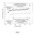
- FIG. 3 is a graph plotting the storage moduli of the kneaded positive electrode material and the kneaded negative electrode material at each temperature shown in TABLE-1.
- the storage modulus of the kneaded electrode material 21 at each temperature indicates different values between the kneaded positive electrode material and the kneaded negative electrode material, the change rate of the storage modulus largely varies and the storage modulus becomes unstable in a temperature range in the range between 20 to 29 [°C] normally set as a room temperature for both the kneaded positive electrode material and the kneaded negative electrode material.
- the kneaded electrode material 21 (kneaded positive electrode material and kneaded negative electrode material) is stable in a state where the active material, the conductive assistant and the binder are uniformly dispersed. At this time, in the vicinity of the room temperature, the kneaded electrode material 21 is stable in a state where binder molecules are adhering to the surfaces of active material fine particles and conductive assistant fine particles (colloidal state). However, if the temperature is raised from the vicinity of the room temperature, the binder molecules desorb from the surfaces of the active material fine particles and the conductive assistant fine particles as the temperature increases, whereby interaction, i.e. repulsive forces between the active material fine particles and the conductive assistant fine particles increase. This is thought to increase the storage modulus of the kneaded electrode material 21.
- the storage modulus takes a substantially constant value and the storage modulus becomes stable in a temperature range from about 35 [°C] to 65 [°C]. If 65 [°C] is exceeded, the storage modulus increases again, the change rate becomes larger and the storage modulus becomes unstable. This is thought to be because, in the case of the kneaded positive electrode material, cross-linking reaction of the binder molecules progresses and the gelling of the kneaded positive electrode material is promoted if 65 [°C] is exceeded.
- the storage modulus takes a substantially constant value and the storage modulus becomes stable in a temperature range from about 35 [°C] to 70 [°C].
- the storage modulus is thought to indicate repulsive forces resulting from steric hindrance between the active material fine particles and the conductive assistant fine particles in the kneaded electrode material 21. If the storage modulus of the kneaded electrode material 21 increases while the kneaded electrode material 21 is applied to the current collector, a feed amount changes and a coating amount is no longer stable even if the kneaded electrode material 21 is extruded at a constant pressure.
- the storage modulus largely varies even when the temperature of the kneaded electrode material 21 is raised by about several degrees Celsius by the supply pump 32 and the like.
- a fine adjustment is necessary to make the coating amount stable after the start of application of the kneaded electrode material 21 and time is required until stable coating can be performed.
- the kneaded electrode material 21 is applied to the current collector while the temperature of the kneaded electrode material 21 is maintained at the predetermined temperature at which the storage modulus of the kneaded electrode material 21 becomes stable (35 [°C] to 65 [°C] in the case of the kneaded positive electrode material, 35 [°C] to 70 [°C] in the case of the kneaded negative electrode material).
- the upper limit of the predetermined temperature is set at 70 [°C] in the case of applying the kneaded negative electrode material to the current collector because the kneaded negative electrode material is more likely to be dried and solidified at a discharge opening of the slit die 33 and it becomes difficult to apply the kneaded negative electrode material to have uniform thickness and the like if an upper limit higher than this is set.
- the kneaded electrode material 21 kneaded in the kneading apparatus 20 is first fed under pressure by the supply pump 32 with the recovery valve 35 opened. This causes the kneaded electrode material 21 to be filled in the supply pipe 31 from the supply pump 32 to the recovery valve 35.
- the temperature of the kneaded electrode material 21 is detected by the thermocouple 38 provided in the recovery pipe 34. After the temperature of the kneaded electrode material 21 reaches the predetermined temperature at which the storage modulus of the kneaded electrode material 21 becomes stable, the recovery valve 35 is closed, the kneaded electrode material 21 is supplied to the slit die 33, and the kneaded electrode material 21 is extruded through the slit die 33 to be applied to the metal foil 14.
- the kneaded electrode material 21 is not affected by a temperature change due to heat received from the coating apparatus components such as the supply pump 32 since the kneaded electrode material 21 is applied to the metal foil 14 after the temperature of the kneaded electrode material 21 is adjusted to the predetermined temperature at which the storage modulus of the kneaded electrode material 21 becomes stable.
- a property variation of the kneaded electrode material 21 due to a temperature change can be reduced and stable coating can be performed from the start of application of the kneaded electrode material 21.
- fine adjustments and the like to make the coating amount stable after the start of coating become unnecessary, wherefore an adjustment time for that can be shortened. Since this can shorten a time required for the coating process, production efficiency of the lithium-ion secondary battery can be improved.
- the predetermined temperature is desirably set within the range of 60 [°C] ⁇ 5 [°C].
- any slurry-like kneaded material having viscoelasticity can be stably applied using the coating apparatus according to this embodiment.
- a water-based material using water as a solvent and a mixture of styrene butadiene rubber (SBR) and methylcellulose acetate (CMC), which is a thickener, as a binder can be cited as the slurry-like kneaded material having viscoelasticity.
- the temperature of the kneaded electrode material 21 is kept at the predetermined temperature by circulating the hot water in the above embodiment
- the temperature of the kneaded electrode material 21 may be kept at the predetermined temperature by including a heating element such as a ribbon heater in the supply pipe 31.
- the method for circulating the hot water as in the above embodiment is more preferable in view of safety and facility maintainability.
Landscapes
- Engineering & Computer Science (AREA)
- Chemical & Material Sciences (AREA)
- Manufacturing & Machinery (AREA)
- Chemical Kinetics & Catalysis (AREA)
- Electrochemistry (AREA)
- General Chemical & Material Sciences (AREA)
- Materials Engineering (AREA)
- Battery Electrode And Active Subsutance (AREA)
- Coating Apparatus (AREA)
Abstract
Description
- This invention relates to a coating apparatus.
-
JP2007-66744A - However, in the conventional coating apparatus described above, in the case of applying a slurry-like kneaded electrode material prepared by kneading an electrode material and a solvent, the kneaded electrode material has received heat from coating apparatus components such as a pump. This causes unstable properties due to a temperature variation of the kneaded electrode material until a specified time elapses after the start of coating, whereby the coating amount varies and stable coating cannot be performed. Thus, there has been a problem of requiring time until the coating amount becomes constant from the start of coating.
- The present invention was developed in view of such a problem and an object thereof is to shorten a time required until a coating amount becomes constant after the start of coating.
- To achieve the above object, the present invention includes a coating unit for applying a slurry-like kneaded electrode material prepared by kneading an electrode material and a solvent, a pump for feeding the kneaded electrode material under pressure to the coating unit, and a temperature raising unit for raising the temperature of the electrode material before coating to a predetermined temperature range where a storage modulus of the kneaded electrode material becomes substantially constant.
- An embodiment and advantages of the present invention are described in detail below with reference to the accompanying drawings.
-
-
FIGS. 1 are schematic views of a lithium-ion secondary battery, -
FIG. 2 is a schematic configuration diagram of an electrode manufacturing apparatus, -
FIG 3 is a graph plotting storage moduli of a kneaded positive electrode material and a kneaded negative electrode material at each temperature shown in TABLE-1. - Hereinafter, an embodiment of the present invention is described with reference to the drawings and the like.
-
FIGS. 1 are schematic views of a lithium-ionsecondary battery 1.FIG. 1(A) is a perspective view of the lithium-ionsecondary battery 1 andFIG. 1(B) is a sectional view along B-B ofFIG. 1(A) . - As shown in
FIGS. 1(A) and 1(B) , the lithium-ionsecondary battery 1 includes astorage element 2 and anexterior case 3 for housing thestorage element 2. - The
storage element 2 is formed as a laminated body in whichpositive electrodes 4,separators 5 as electrolyte layers andnegative electrodes 6 are successively laminated. Thepositive electrode 4 includespositive electrode layers 4b on opposite surfaces of a plate-like positive electrodecurrent collector 4a, and thenegative electrode 6 includesnegative electrode layers 6b on opposite surfaces of a plate-like negativeelectrode current collector 6a. Note that, for thepositive electrode 4 arranged in the outermost layer of thestorage element 2, thepositive electrode layer 4b is formed only on one surface of the positive electrodecurrent collector 4a. - The adjacent
positive electrode 4,separator 5 andnegative electrode 6 form oneunit cell 7, and the lithium-ion battery 1 is formed by electrically connecting a plurality of laminatedunit cells 7 in parallel. - The
exterior case 3 is made of a polymer-metal complex laminated film sheet material in which a metal such as aluminum is covered with an insulator such as a polypropylene film. Outer peripheral parts of theexterior case 3 are joined by thermal fusion with thestorage element 2 housed in theexterior case 3. Thisexterior case 3 is provided with apositive electrode tab 8 and anegative electrode tab 9 as external terminals to take out power from thestorage element 2 to the outside. - One end of the
positive electrode tab 8 is located outside theexterior case 3 and the other end of thepositive electrode tab 8 is connected to an aggregate of each positive electrodecurrent collector 4a inside theexterior case 3. One end of thenegative electrode tab 9 is located outside theexterior case 3 and the other end of thenegative electrode tab 9 is connected to an aggregate of each negativeelectrode current collector 6a inside theexterior case 3. - Next, a general manufacturing method for an electrode (
positive electrode 4 or negative electrode 6) is briefly described. - Generally, an electrode is manufactured by way of a coating process of applying a slurry-like kneaded electrode material prepared by kneading an electrode material and a solvent to a current collector (positive
electrode current collector 4a or negativeelectrode current collector 6a) and then a drying process of volatizing the solvent of the kneaded electrode material to form an electrode layer (positive-electrode layer 4b ornegative electrode layer 6b) which is 100 % of solid content. - Here, to improve production efficiency of the lithium-ion
secondary battery 1, it is effective to shorten a time required for each process described above. Accordingly, in this embodiment, a time required for the coating process is shortened by suppressing a temperature variation of the kneaded electrode material in the coating process and making a coating amount stable in an early stage. Anelectrode manufacturing apparatus 100 according to this embodiment is described below. -
FIG. 2 is a schematic configuration diagram of theelectrode manufacturing apparatus 100 according to this embodiment used at the time of manufacturing the electrodes of the lithium-ionsecondary battery 1. - The
electrode manufacturing apparatus 100 includes aconveying apparatus 10, akneading apparatus 20, acoating apparatus 30, adrying apparatus 40 and acontroller 50. - The
electrode manufacturing apparatus 100 is an apparatus for manufacturing an electrode by applying a kneadedelectrode material 21 kneaded by the kneadingapparatus 20 to a surface of ametal foil 14 conveyed by the conveyingapparatus 10 by thecoating apparatus 30 and drying the kneadedelectrode material 21 by thedrying apparatus 40. If necessary, the electrode may be pressed by a press apparatus after drying to adjust the thickness and the like. - Each apparatus constituting the
electrode manufacturing apparatus 100 is described in detail below. - The
conveying apparatus 10 includes anunwind roll 11, a take-up roll 12, andsupport rolls 13. Theconveying apparatus 10 conveys a metal foil (having a thickness of 10 [µm] to 40 [µm]) 14 in the form of a thin film, which becomes the positive electrodecurrent collector 4a or the negativeelectrode current collector 6a, from theunwind roll 11 to the take-up roll 12 by a roll-to-roll method. - In this embodiment, an aluminum foil is used as the
metal foil 14 that becomes the positiveelectrode current collector 4a in the case of manufacturing thepositive electrode 4 and a copper foil is used as themetal foil 14 that becomes the negativeelectrode current collector 6a in the case of manufacturing thenegative electrode 6. However, there is no limitation to this. - The
metal foil 14 is wound on theunwind roll 11. Theunwind roll 11 includes abraking mechanism 15, and the rotation of theunwind roll 11 is appropriately restricted by thisbraking mechanism 15 to apply a predetermined tension to themetal foil 14. - The take-
up roll 12 is driven and rotated by adrive motor 16 and takes up themetal foil 14 pulled from theunwind roll 11. - A plurality of
support rolls 13 are provided in a metal foil conveyance path between theunwind roll 11 and the take-up roll 12 and hold the lower surface of themetal foil 14 being conveyed. - The
kneading apparatus 20 is a twin screw kneader and produces the slurry-like kneadedelectrode material 21 by uniformly dispersing the electrode material in the solvent. Thekneading apparatus 20 is not limited to the twin screw kneader and, for example, a planetary mixer or kneader may be used. - The kneaded
electrode material 21 includes a kneaded positive electrode material produced in the case of manufacturing thepositive electrode 4 and a kneaded negative electrode material produced in the case of manufacturing thenegative electrode 6. - In the case of manufacturing the kneaded positive electrode material, a positive electrode active material as the electrode material, a conductive assistant and a binder are poured into the
kneading apparatus 20 and these are uniformly dispersed in the solvent. In the case of manufacturing the kneaded negative electrode material, a negative electrode active material as the electrode material, a conductive assistant and a binder are poured into thekneading apparatus 20 and these are uniformly dispersed in the solvent. - The positive electrode active material is a material which stores and releases lithium ions of lithium metal oxides and the like. In this embodiment, lithium manganate is used as the positive electrode active material.
- The negative electrode active material is a material which stores and release lithium ions of hard carbons, graphites and the like. In this embodiment, hard carbon is used as the negative electrode active material.
- The conductive assistant is a substance for improving conductivity of a carbon material (carbon powder, carbon fibers) and the like. Various carbon blacks such as acetylene black, furnace black and Ketjen Black and graphite powder can be used as the carbon powder. In this embodiment, carbon black is used as the conductive assistant both in the case of producing the kneaded positive electrode material and in the case of producing the kneaded negative electrode material.
- The binder is a substance for binding active material fine particles to each other. In this embodiment, polyvinylidene fluoride (PVDF) is used as the binder both in the case of producing the kneaded positive electrode material and in the case of producing the kneaded negative electrode material, but there is no limitation to this.
- The solvent is a liquid for dissolving the electrode material. In this embodiment, N-methylpyrrolidone (NMP) is used as the solvent both in the case of producing the kneaded positive electrode material and in the case of producing the kneaded negative electrode material, but there is no limitation to this.
- The
coating apparatus 30 is an apparatus for applying the kneadedelectrode material 21 produced in thekneading apparatus 20 to the surface of themetal foil 14 and includes asupply pipe 31, asupply pump 32, aslit die 33, arecovery pipe 34, arecovery valve 35, a hotwater circulating pipe 36, ahot water tank 37 and a thermocouple 38. - The
supply pipe 31 is a pipe having one end connected to a lower side of thekneading apparatus 20 and the other end connected to theslit die 33. - The
supply pump 32 is provided in thesupply pipe 31 and feeds the kneadedelectrode material 21 produced in the kneadingapparatus 20 to theslit ide 33 via thesupply pipe 31. - The slit die 33 extrudes the kneaded
electrode material 21 fed from thesupply pump 32 from aslit 331 formed at a leading end part and applies it to the surface of themetal foil 14 being conveyed. The slit die 33 extrudes and applies the kneadedelectrode material 21 at specified intervals in a conveying direction of themetal foil 14 and at a right angle to the conveying direction. - The
recovery pipe 34 is a pipe having one end connected to thesupply pipe 31 between thesupply pump 32 and the slit die 33 and the other end connected to an upper side of the kneadingapparatus 20. - The
recovery valve 35 is provided at a junction between thesupply pipe 31 and therecovery pipe 34. If therecovery valve 35 is open, the kneadedelectrode material 21 fed under pressure from thesupply pump 32 is returned to the kneadingapparatus 20 via therecovery pipe 34. On the other hand, if therecovery valve 35 is closed, the kneadedelectrode material 21 fed under pressure from thesupply pump 32 is supplied to the slit die 33 via thesupply pipe 31. - The hot
water circulating pipe 36 is a pipe formed to cover the outer periphery of thesupply pipe 31 from thesupply pump 32 to the slit die 33, and both ends thereof are connected to thehot water tank 37 to circulate hot water. As just described, a double pipe structure is adopted from thesupply pump 32 to the slit die 33, and the temperature of the kneadedelectrode material 21 flowing in thesupply pipe 31 from thesupply pump 32 to the slit die 33 is maintained at a predetermined temperature, at which a degree of elasticity (hereinafter, referred to as a "storage modulus (G')") of the kneadedelectrode material 21 becomes stable, by the hot water circulating in the hotwater circulating pipe 36. - The
hot water tank 37 stores water that circulates in the hotwater circulating pipe 36. Thehot water tank 37 includes atemperature raiser 371. Thetemperature raiser 371 raises the temperature of the stored water to a set temperature to obtain hot water. - The thermocouple 38 detects the temperature of the kneaded
electrode material 21 flowing in therecovery pipe 34. - The drying
apparatus 40 is, for example, a hot-air drying furnace and provided in the metal foil conveyance path. The dryingapparatus 40 blows hot air to the kneadedelectrode material 21 while maintaining a temperature in the apparatus at a predetermined temperature, thereby volatizing the solvent in the kneadedelectrode material 21 to form an electrode layer which is 100 % of solid content. - The
controller 50 is configured by a microcomputer including a central processing unit (CPU), a read only memory (ROM), a random access memory (RAM) and an input/output interface (I/O interface). The temperature of the kneadedelectrode material 21 detected by the thermocouple 38 is input to thecontroller 50. Thecontroller 50 opens and closes therecovery valve 35 based on the input temperature of the kneadedelectrode material 21. Specifically, therecovery valve 35 is open until the temperature of the kneadedelectrode material 21 reaches the predetermined temperature at which the storage modulus of the kneadedelectrode material 21 becomes stable, and is closed when the predetermined temperature is reached. - Here, the reason why the temperature of the kneaded
electrode material 21 flowing in thesupply pipe 31 from thesupply pump 32 to the slit die 33 is maintained at the predetermined temperature, at which the storage modulus of the kneadedelectrode material 21 becomes stable, by the hot water circulating in the hotwater circulating pipe 36 is described with reference to TABLE-1 andFIG. 3 . - In this embodiment, that "the storage modulus of the kneaded
electrode material 21 becomes stable" means that a change rate of the storage modulus of the kneadedelectrode material 21 when the temperature is raised by 1 [°C] is within 5 %. The change rate of the storage modulus is defined by the following equation.
- TABLE-1 is a table showing the storage moduli of the kneaded positive electrode material and the kneaded negative electrode material at each temperature when the temperature is raised by about 2 [°C] and the change rates of the storage moduli of the kneaded positive electrode material and the kneaded negative electrode material at that time.
-
[TABLE-1] Storage Modulus G' (Pa) Change Rate (%) Temperature (°C) Positive Electrode Negative Electrode Positive Electrode Negative Electrode 25.6 9.8 3.3 27.7 11.1 5.6 13% 68% 29.9 11.5 7.8 3% 39% 32.2 11.6 8.3 1% 6% 34.5 12.1 8.3 4% 0% 36.8 11.9 8.7 -2% 5% 39.2 12.0 8.7 1% 0% 41.6 12.1 8.9 1% 2% 43.9 12.3 8.5 2% -5% 46.3 11.9 8.8 -4% 4% 48.6 12.1 8.9 2% 2% 51.0 12.2 8.8 1% -2% 53.3 12.2 9.0 0% 3% 55.8 12.5 8.7 3% -4% 58.1 12.4 9.0 -2% 3% 60.5 12.4 9.1 1% 2% 62.9 12.5 9.3 1% 2% 65.2 12.6 8.9 0% -4% 67.5 13.4 9.0 7% 0% 69.7 16.3 9.4 21% 5% -
FIG. 3 is a graph plotting the storage moduli of the kneaded positive electrode material and the kneaded negative electrode material at each temperature shown in TABLE-1. - As shown in TABLE-1 and
FIG. 3 , the storage modulus of the kneadedelectrode material 21 at each temperature indicates different values between the kneaded positive electrode material and the kneaded negative electrode material, the change rate of the storage modulus largely varies and the storage modulus becomes unstable in a temperature range in the range between 20 to 29 [°C] normally set as a room temperature for both the kneaded positive electrode material and the kneaded negative electrode material. - The kneaded electrode material 21 (kneaded positive electrode material and kneaded negative electrode material) is stable in a state where the active material, the conductive assistant and the binder are uniformly dispersed. At this time, in the vicinity of the room temperature, the kneaded
electrode material 21 is stable in a state where binder molecules are adhering to the surfaces of active material fine particles and conductive assistant fine particles (colloidal state). However, if the temperature is raised from the vicinity of the room temperature, the binder molecules desorb from the surfaces of the active material fine particles and the conductive assistant fine particles as the temperature increases, whereby interaction, i.e. repulsive forces between the active material fine particles and the conductive assistant fine particles increase. This is thought to increase the storage modulus of the kneadedelectrode material 21. - In the case of the kneaded positive electrode material, the storage modulus takes a substantially constant value and the storage modulus becomes stable in a temperature range from about 35 [°C] to 65 [°C]. If 65 [°C] is exceeded, the storage modulus increases again, the change rate becomes larger and the storage modulus becomes unstable. This is thought to be because, in the case of the kneaded positive electrode material, cross-linking reaction of the binder molecules progresses and the gelling of the kneaded positive electrode material is promoted if 65 [°C] is exceeded.
- On the other hand, in the case of the kneaded negative electrode material, the storage modulus takes a substantially constant value and the storage modulus becomes stable in a temperature range from about 35 [°C] to 70 [°C].
- As just described, the storage modulus is thought to indicate repulsive forces resulting from steric hindrance between the active material fine particles and the conductive assistant fine particles in the kneaded
electrode material 21. If the storage modulus of the kneadedelectrode material 21 increases while the kneadedelectrode material 21 is applied to the current collector, a feed amount changes and a coating amount is no longer stable even if the kneadedelectrode material 21 is extruded at a constant pressure. - Accordingly, in the case of applying the kneaded
electrode material 21 in the vicinity of the room temperature, the storage modulus largely varies even when the temperature of the kneadedelectrode material 21 is raised by about several degrees Celsius by thesupply pump 32 and the like. Thus, a fine adjustment is necessary to make the coating amount stable after the start of application of the kneadedelectrode material 21 and time is required until stable coating can be performed. - Accordingly, in this embodiment, the kneaded
electrode material 21 is applied to the current collector while the temperature of the kneadedelectrode material 21 is maintained at the predetermined temperature at which the storage modulus of the kneadedelectrode material 21 becomes stable (35 [°C] to 65 [°C] in the case of the kneaded positive electrode material, 35 [°C] to 70 [°C] in the case of the kneaded negative electrode material). Note that the upper limit of the predetermined temperature is set at 70 [°C] in the case of applying the kneaded negative electrode material to the current collector because the kneaded negative electrode material is more likely to be dried and solidified at a discharge opening of the slit die 33 and it becomes difficult to apply the kneaded negative electrode material to have uniform thickness and the like if an upper limit higher than this is set. - Next, functions of the electrode manufacturing apparatus according to this embodiment are described.
- The kneaded
electrode material 21 kneaded in the kneadingapparatus 20 is first fed under pressure by thesupply pump 32 with therecovery valve 35 opened. This causes the kneadedelectrode material 21 to be filled in thesupply pipe 31 from thesupply pump 32 to therecovery valve 35. - Subsequently, after the temperature of the water in the hot water tank is raised to a temperature at which the temperature of the kneaded
electrode material 21 can be raised to the predetermined temperature at which the storage modulus becomes stable, thereby obtaining hot water, this hot water is flowed and circulated in the hotwater recovery pipe 36. In this way, the temperature of the kneadedelectrode material 21 filled in thesupply pipe 31 from thesupply pump 32 to therecovery valve 35 is adjusted to the predetermined temperature at which the storage modulus of the kneadedelectrode material 21 becomes stable. - Then, the temperature of the kneaded
electrode material 21 is detected by the thermocouple 38 provided in therecovery pipe 34. After the temperature of the kneadedelectrode material 21 reaches the predetermined temperature at which the storage modulus of the kneadedelectrode material 21 becomes stable, therecovery valve 35 is closed, the kneadedelectrode material 21 is supplied to the slit die 33, and the kneadedelectrode material 21 is extruded through the slit die 33 to be applied to themetal foil 14. - In this way, according to this embodiment described above, the kneaded
electrode material 21 is not affected by a temperature change due to heat received from the coating apparatus components such as thesupply pump 32 since the kneadedelectrode material 21 is applied to themetal foil 14 after the temperature of the kneadedelectrode material 21 is adjusted to the predetermined temperature at which the storage modulus of the kneadedelectrode material 21 becomes stable. Thus, a property variation of the kneadedelectrode material 21 due to a temperature change can be reduced and stable coating can be performed from the start of application of the kneadedelectrode material 21. As a result, fine adjustments and the like to make the coating amount stable after the start of coating become unnecessary, wherefore an adjustment time for that can be shortened. Since this can shorten a time required for the coating process, production efficiency of the lithium-ion secondary battery can be improved. - Further, since the temperature of the kneaded
electrode material 21 to be applied is increased to the predetermined temperature higher than the room temperature in advance, the length of the drying furnace can be shortened and a drying time can also be shortened in the drying process after the coating process. Thus, production efficiency of the lithium-ionsecondary battery 1 can be further improved. To effectively achieve such an effect, the predetermined temperature is desirably set within the range of 60 [°C]±5 [°C]. - Although this invention has been described by way of the specific embodiment, this invention is not limited to the above embodiment. It is possible for a person skilled in the art to modify or alter the above embodiment in various manners within the technical scope of the present invention.
- For example, without being limited to the kneaded
electrode material 21 illustrated in the above embodiment, any slurry-like kneaded material having viscoelasticity can be stably applied using the coating apparatus according to this embodiment. A water-based material using water as a solvent and a mixture of styrene butadiene rubber (SBR) and methylcellulose acetate (CMC), which is a thickener, as a binder can be cited as the slurry-like kneaded material having viscoelasticity. - Further, although the temperature of the kneaded
electrode material 21 is kept at the predetermined temperature by circulating the hot water in the above embodiment, the temperature of the kneadedelectrode material 21 may be kept at the predetermined temperature by including a heating element such as a ribbon heater in thesupply pipe 31. However, the method for circulating the hot water as in the above embodiment is more preferable in view of safety and facility maintainability. - For the above description, the contents of Japanese Patent Application No.
2010-114297 filed on May 18, 2010
Claims (6)
- A coating apparatus, comprising:a coating unit for applying a slurry-like kneaded electrode material prepared by kneading an electrode material and a solvent;a pump for feeding the kneaded electrode material under pressure to the coating unit; anda temperature raising unit for raising the temperature of the kneaded electrode material before coating to a predetermined temperature range where a storage modulus of the kneaded electrode material becomes substantially constant.
- The coating apparatus according to claim 1, further comprising a pipe for connecting the coating unit and the pump,
wherein the temperature raising unit raises the temperature of the kneaded electrode material flowing in the pipe to the predetermined temperature range. - The coating apparatus according to claim 2, wherein the temperature raising unit is a pipe which is formed to cover the outer periphery of the pipe and in which hot water circulates.
- The coating apparatus according to any one of claims 1 to 3, wherein the predetermined temperature range is a temperature range where a change rate of the storage modulus of the kneaded electrode material is within 5 % when the temperature of the kneaded electrode material is raised by 1°C.
- The coating apparatus according to any one of claims 1 to 3, wherein the predetermined temperature range is a range from 35°C to 65°C when the kneaded electrode material is a kneaded positive electrode material.
- The coating apparatus according to any one of claims 1 to 3, wherein the predetermined temperature range is a range from 35°C to 70°C when the kneaded electrode material is a kneaded negative electrode material.
Applications Claiming Priority (2)
| Application Number | Priority Date | Filing Date | Title |
|---|---|---|---|
| JP2010114297 | 2010-05-18 | ||
| PCT/JP2011/061185 WO2011145556A1 (en) | 2010-05-18 | 2011-05-16 | Coating apparatus |
Publications (2)
| Publication Number | Publication Date |
|---|---|
| EP2573840A1 true EP2573840A1 (en) | 2013-03-27 |
| EP2573840A4 EP2573840A4 (en) | 2013-12-04 |
Family
ID=44991659
Family Applications (1)
| Application Number | Title | Priority Date | Filing Date |
|---|---|---|---|
| EP11783490.3A Withdrawn EP2573840A4 (en) | 2010-05-18 | 2011-05-16 | Coating apparatus |
Country Status (6)
| Country | Link |
|---|---|
| US (1) | US20130056092A1 (en) |
| EP (1) | EP2573840A4 (en) |
| JP (1) | JP5644856B2 (en) |
| KR (2) | KR20150043520A (en) |
| CN (1) | CN102884657B (en) |
| WO (1) | WO2011145556A1 (en) |
Cited By (4)
| Publication number | Priority date | Publication date | Assignee | Title |
|---|---|---|---|---|
| EP2667431A3 (en) * | 2012-05-22 | 2015-08-26 | Jtekt Corporation | Electrode production system |
| EP2667432A3 (en) * | 2012-05-22 | 2015-09-02 | Jtekt Corporation | Electrode production system |
| EP3327829A4 (en) * | 2015-07-17 | 2018-12-26 | Eliiy Power Co., Ltd. | Battery electrode slurry distribution device, battery electrode slurry treatment device, battery electrode slurry distribution method, suspension distribution device, suspension distribution method, battery electrode slurry treatment method, fabrication device, and fabrication method |
| EP4181226A4 (en) * | 2021-08-27 | 2025-04-16 | LG Energy Solution, Ltd. | Secondary battery electrode slurry coating apparatus and electrode slurry coating method therewith |
Families Citing this family (3)
| Publication number | Priority date | Publication date | Assignee | Title |
|---|---|---|---|---|
| KR102040511B1 (en) * | 2016-09-09 | 2019-11-05 | 주식회사 엘지화학 | Electrode coating apparatus |
| KR102748260B1 (en) * | 2021-11-18 | 2024-12-27 | 주식회사 엘지에너지솔루션 | Supply device for electrode slurry and supply method for the same |
| KR20240159131A (en) | 2023-04-28 | 2024-11-05 | 주식회사 엘지에너지솔루션 | Electrode slurry circulation system and electrode slurry circulation method using the same |
Family Cites Families (8)
| Publication number | Priority date | Publication date | Assignee | Title |
|---|---|---|---|---|
| US3853410A (en) * | 1971-10-22 | 1974-12-10 | R Busoni | Device for distributing hot-melt adhesive |
| DE69408917T2 (en) * | 1993-06-15 | 1998-06-25 | Fuji Photo Film Co Ltd | Process for the production of sheet-like plates |
| JP2004199916A (en) * | 2002-12-17 | 2004-07-15 | Matsushita Electric Ind Co Ltd | Method for producing electrode of lithium ion secondary battery |
| US20040119194A1 (en) * | 2002-12-24 | 2004-06-24 | Boyko Aladjov | Method for making electrodes for electrochemical cells |
| JP4157404B2 (en) * | 2003-03-27 | 2008-10-01 | 株式会社東芝 | Method for manufacturing sheet electrode plate and non-aqueous electrolyte battery |
| US7694894B2 (en) * | 2005-04-19 | 2010-04-13 | Warren Environmental, Inc. | Method and system for preheating epoxy coatings for spray application |
| JP2008029962A (en) * | 2006-07-28 | 2008-02-14 | Toyota Motor Corp | Apparatus and method for applying paste containing water repellent substance, and method for manufacturing fuel cell |
| JP5003695B2 (en) * | 2009-02-04 | 2012-08-15 | トヨタ自動車株式会社 | Electrode slurry manufacturing method and electrode slurry manufacturing apparatus |
-
2011
- 2011-05-16 WO PCT/JP2011/061185 patent/WO2011145556A1/en not_active Ceased
- 2011-05-16 KR KR1020157008206A patent/KR20150043520A/en not_active Ceased
- 2011-05-16 KR KR1020127032909A patent/KR20130030764A/en not_active Ceased
- 2011-05-16 JP JP2012515876A patent/JP5644856B2/en not_active Expired - Fee Related
- 2011-05-16 CN CN201180022026.0A patent/CN102884657B/en not_active Expired - Fee Related
- 2011-05-16 EP EP11783490.3A patent/EP2573840A4/en not_active Withdrawn
- 2011-05-16 US US13/697,454 patent/US20130056092A1/en not_active Abandoned
Cited By (5)
| Publication number | Priority date | Publication date | Assignee | Title |
|---|---|---|---|---|
| EP2667431A3 (en) * | 2012-05-22 | 2015-08-26 | Jtekt Corporation | Electrode production system |
| EP2667432A3 (en) * | 2012-05-22 | 2015-09-02 | Jtekt Corporation | Electrode production system |
| EP3327829A4 (en) * | 2015-07-17 | 2018-12-26 | Eliiy Power Co., Ltd. | Battery electrode slurry distribution device, battery electrode slurry treatment device, battery electrode slurry distribution method, suspension distribution device, suspension distribution method, battery electrode slurry treatment method, fabrication device, and fabrication method |
| US10566602B2 (en) | 2015-07-17 | 2020-02-18 | Eliiy Power Co., Ltd. | Distribution and processing of battery electrode slurry and similar suspensions |
| EP4181226A4 (en) * | 2021-08-27 | 2025-04-16 | LG Energy Solution, Ltd. | Secondary battery electrode slurry coating apparatus and electrode slurry coating method therewith |
Also Published As
| Publication number | Publication date |
|---|---|
| CN102884657A (en) | 2013-01-16 |
| JPWO2011145556A1 (en) | 2013-07-22 |
| KR20130030764A (en) | 2013-03-27 |
| US20130056092A1 (en) | 2013-03-07 |
| CN102884657B (en) | 2016-01-06 |
| JP5644856B2 (en) | 2014-12-24 |
| WO2011145556A1 (en) | 2011-11-24 |
| EP2573840A4 (en) | 2013-12-04 |
| KR20150043520A (en) | 2015-04-22 |
Similar Documents
| Publication | Publication Date | Title |
|---|---|---|
| US20130056092A1 (en) | Coating apparatus | |
| CN106804115B (en) | Method for manufacturing lithium ion secondary battery electrode | |
| JP3953911B2 (en) | Method for producing coating sheet | |
| US7307831B2 (en) | Method of manufacturing electrode and electrode | |
| JP5499537B2 (en) | Electrode manufacturing apparatus and electrode manufacturing method | |
| CN108352497B (en) | Electrode coating equipment | |
| CN100355124C (en) | Composite particle for electrode and its manufacturing method, electrode and its manufacturing method, electrochemical element and its manufacturing method | |
| WO2010082230A1 (en) | Method for producing plate of battery | |
| KR101510509B1 (en) | Method for manufacturing a battery electrode | |
| KR101361259B1 (en) | Electrode production method and repair material of electrode | |
| JP2016115576A (en) | Manufacturing method of lithium ion battery, manufacturing device of lithium ion battery and lithium ion battery | |
| JP2003151538A (en) | Manufacturing method of electrode composite for secondary battery and its device | |
| KR20130044160A (en) | Electrode, electrode manufacturing apparatus and electrode manufacturing method | |
| CN114695837B (en) | Method and device for producing electrode for non-aqueous electrolyte secondary battery | |
| CN115084442B (en) | Method for manufacturing electrode for secondary battery | |
| JP5509998B2 (en) | Electrode manufacturing apparatus and electrode manufacturing method | |
| JP4179758B2 (en) | Electrode manufacturing method and apparatus used in the method | |
| CN116134262A (en) | Secondary battery electrode slurry coating device and electrode slurry coating method using the same | |
| CN115050919B (en) | Method for producing electrode for secondary battery and method for producing secondary battery | |
| JP2015173034A (en) | Method and apparatus for producing electrode for non-aqueous electrolyte secondary battery | |
| KR101383054B1 (en) | Manufacturing method of cathode of lithium primary battery | |
| US20250316678A1 (en) | Apparatus and method for manufacturing secondary battery for improvement of brittleness of electrode plate |
Legal Events
| Date | Code | Title | Description |
|---|---|---|---|
| PUAI | Public reference made under article 153(3) epc to a published international application that has entered the european phase |
Free format text: ORIGINAL CODE: 0009012 |
|
| 17P | Request for examination filed |
Effective date: 20121218 |
|
| AK | Designated contracting states |
Kind code of ref document: A1 Designated state(s): AL AT BE BG CH CY CZ DE DK EE ES FI FR GB GR HR HU IE IS IT LI LT LU LV MC MK MT NL NO PL PT RO RS SE SI SK SM TR |
|
| DAX | Request for extension of the european patent (deleted) | ||
| A4 | Supplementary search report drawn up and despatched |
Effective date: 20131106 |
|
| RIC1 | Information provided on ipc code assigned before grant |
Ipc: B05C 5/02 20060101ALI20131030BHEP Ipc: H01M 4/139 20100101ALI20131030BHEP Ipc: H01M 10/04 20060101ALN20131030BHEP Ipc: B05C 11/10 20060101ALI20131030BHEP Ipc: H01M 4/04 20060101AFI20131030BHEP |
|
| 17Q | First examination report despatched |
Effective date: 20140425 |
|
| STAA | Information on the status of an ep patent application or granted ep patent |
Free format text: STATUS: THE APPLICATION HAS BEEN WITHDRAWN |
|
| 18W | Application withdrawn |
Effective date: 20160331 |