EP2573644A2 - Display, electronic unit, and supporting substrate - Google Patents
Display, electronic unit, and supporting substrate Download PDFInfo
- Publication number
- EP2573644A2 EP2573644A2 EP20120180704 EP12180704A EP2573644A2 EP 2573644 A2 EP2573644 A2 EP 2573644A2 EP 20120180704 EP20120180704 EP 20120180704 EP 12180704 A EP12180704 A EP 12180704A EP 2573644 A2 EP2573644 A2 EP 2573644A2
- Authority
- EP
- European Patent Office
- Prior art keywords
- region
- supporting substrate
- display
- section
- edge
- Prior art date
- Legal status (The legal status is an assumption and is not a legal conclusion. Google has not performed a legal analysis and makes no representation as to the accuracy of the status listed.)
- Withdrawn
Links
- 239000000758 substrate Substances 0.000 title claims abstract description 128
- 238000001514 detection method Methods 0.000 claims description 20
- 229920001971 elastomer Polymers 0.000 claims description 5
- 239000000806 elastomer Substances 0.000 claims description 5
- 230000007423 decrease Effects 0.000 claims description 4
- 230000003247 decreasing effect Effects 0.000 claims description 4
- 230000008878 coupling Effects 0.000 description 63
- 238000010168 coupling process Methods 0.000 description 63
- 238000005859 coupling reaction Methods 0.000 description 63
- 230000009471 action Effects 0.000 description 23
- 238000005452 bending Methods 0.000 description 19
- 230000007246 mechanism Effects 0.000 description 16
- 239000000463 material Substances 0.000 description 6
- 230000004048 modification Effects 0.000 description 5
- 238000012986 modification Methods 0.000 description 5
- 238000005401 electroluminescence Methods 0.000 description 4
- 239000011347 resin Substances 0.000 description 4
- 229920005989 resin Polymers 0.000 description 4
- 239000010408 film Substances 0.000 description 3
- 230000006870 function Effects 0.000 description 3
- 239000004973 liquid crystal related substance Substances 0.000 description 3
- 239000010409 thin film Substances 0.000 description 3
- PPBRXRYQALVLMV-UHFFFAOYSA-N Styrene Chemical compound C=CC1=CC=CC=C1 PPBRXRYQALVLMV-UHFFFAOYSA-N 0.000 description 2
- 238000001816 cooling Methods 0.000 description 2
- 230000001419 dependent effect Effects 0.000 description 2
- 230000000694 effects Effects 0.000 description 2
- 238000005516 engineering process Methods 0.000 description 2
- 229920002725 thermoplastic elastomer Polymers 0.000 description 2
- JOYRKODLDBILNP-UHFFFAOYSA-N Ethyl urethane Chemical compound CCOC(N)=O JOYRKODLDBILNP-UHFFFAOYSA-N 0.000 description 1
- PXGOKWXKJXAPGV-UHFFFAOYSA-N Fluorine Chemical compound FF PXGOKWXKJXAPGV-UHFFFAOYSA-N 0.000 description 1
- 230000001133 acceleration Effects 0.000 description 1
- 150000001336 alkenes Chemical class 0.000 description 1
- 230000004075 alteration Effects 0.000 description 1
- 150000001408 amides Chemical class 0.000 description 1
- 238000010586 diagram Methods 0.000 description 1
- 238000006073 displacement reaction Methods 0.000 description 1
- 230000002996 emotional effect Effects 0.000 description 1
- 150000002148 esters Chemical class 0.000 description 1
- 229910052731 fluorine Inorganic materials 0.000 description 1
- 239000011737 fluorine Substances 0.000 description 1
- 238000010438 heat treatment Methods 0.000 description 1
- 238000001746 injection moulding Methods 0.000 description 1
- 238000000034 method Methods 0.000 description 1
- 238000002156 mixing Methods 0.000 description 1
- JRZJOMJEPLMPRA-UHFFFAOYSA-N olefin Natural products CCCCCCCC=C JRZJOMJEPLMPRA-UHFFFAOYSA-N 0.000 description 1
- 239000004033 plastic Substances 0.000 description 1
- 229920001296 polysiloxane Polymers 0.000 description 1
- 230000004044 response Effects 0.000 description 1
- 230000011218 segmentation Effects 0.000 description 1
- 230000035945 sensitivity Effects 0.000 description 1
Images


Classifications
-
- G—PHYSICS
- G06—COMPUTING; CALCULATING OR COUNTING
- G06F—ELECTRIC DIGITAL DATA PROCESSING
- G06F1/00—Details not covered by groups G06F3/00 - G06F13/00 and G06F21/00
- G06F1/16—Constructional details or arrangements
- G06F1/1613—Constructional details or arrangements for portable computers
- G06F1/1633—Constructional details or arrangements of portable computers not specific to the type of enclosures covered by groups G06F1/1615 - G06F1/1626
- G06F1/1637—Details related to the display arrangement, including those related to the mounting of the display in the housing
- G06F1/1652—Details related to the display arrangement, including those related to the mounting of the display in the housing the display being flexible, e.g. mimicking a sheet of paper, or rollable
-
- Y—GENERAL TAGGING OF NEW TECHNOLOGICAL DEVELOPMENTS; GENERAL TAGGING OF CROSS-SECTIONAL TECHNOLOGIES SPANNING OVER SEVERAL SECTIONS OF THE IPC; TECHNICAL SUBJECTS COVERED BY FORMER USPC CROSS-REFERENCE ART COLLECTIONS [XRACs] AND DIGESTS
- Y10—TECHNICAL SUBJECTS COVERED BY FORMER USPC
- Y10T—TECHNICAL SUBJECTS COVERED BY FORMER US CLASSIFICATION
- Y10T428/00—Stock material or miscellaneous articles
- Y10T428/24—Structurally defined web or sheet [e.g., overall dimension, etc.]
- Y10T428/24479—Structurally defined web or sheet [e.g., overall dimension, etc.] including variation in thickness
Definitions
- the present disclosure relates to a thin and flexible display such as a so-called electronic paper.
- e-paper electronic paper
- e-book electronic book
- the above-mentioned displays are thin and highly flexible, it is possible to physically bend and twist the above-mentioned displays.
- This makes it possible to realize various kinds of user interfaces such as those in which a sensor configured to detect bending by a user and the like is incorporated to switch display content in response to such a user operation,
- a sensor configured to detect bending by a user and the like is incorporated to switch display content in response to such a user operation
- a display including a supporting substrate having flexibility; and a display section provided on the supporting substrate.
- the flexibility of the supporting substrate gradually increases toward an edge in a first region provided at at least a portion on a side of the edge in a plane thereof.
- an electronic unit with a display includes a supporting substrate having flexibility; and a display section provided on the supporting substrate.
- the flexibility of the supporting substrate gradually increases toward an edge in a first region provided at at least a portion on a side of the edge in a plane thereof.
- a supporting substrate configured to support a display section and having flexibility.
- the flexibility of the supporting substrate gradually increases toward an edge in a first region provided at at least a portion on a side of the edge in a plane thereof.
- the supporting substrate since the supporting substrate has flexibility, and in the first region provided at at least a portion on a side of an edge in a plane thereof, the flexibility of the supporting substrate gradually increases toward the edge, a user allowed to bend and twist a local portion on the edge side of the whole display with ease.
- the supporting substrate since the supporting substrate has flexibility, and in the first region provided at at least a portion on a side of an edge in a plane thereof, the flexibility of the supporting substrate gradually increases toward the edge, a user is allowed to readily bend and twist a local portion on the edge side of the whole display. Consequently, when display content is switched based on a user operation associated with a variation in a physical form, excellent operability is realized.
- FIGs. 1A and 1B each schematically show a perspective configuration of a display (electronic book 1) according to an embodiment of the present disclosure.
- FIG. 2 is an exploded perspective view of the electronic book 1 (one side portion).
- FIG. 3 is a plan view of the electronic book 1
- FIG. 4 is a bottom view
- FIG. 5 is a front view (similar to a back view)
- FIG. 6 is a right side view (similar to a left side view). It should be noted that, a hinge section 12 is not shown in FIG. 3 to FIG. 6 .
- the electronic book 1 is a thin and flexible display formed with use of a flexible material as a component, In the electronic book 1, the whole unit may be closed (folded) or opened as is the case with a real book made by putting together a plurality of papers (pages). A user is allowed to browse content (a page or the like of a book, for example) displayed on the electronic book 1 with a feeling like actually reading a book.
- the electronic book 1 is provided with, on a supporting substrate 10, a laminated body 11 including a display section 15, and, at a portion corresponding to a "spine" (spine la) of a book, the hinge section 12.
- a cover 13 is provided, and the top face side (a side that faces inside in a closed state) thereof is covered with a protect sheet 14.
- the supporting substrate 10 supports the laminated body 11 and has flexibility.
- the flexibility of the supporting substrate 10 differs among regions thereof.
- the thickness of the supporting substrate 10 varies in a plane thereof, and this results in the variation of flexibility. Detailed configuration of the supporting substrate 10 will be described later.
- the laminated body 11 has a structure in which a system board layer 17, a driving circuit section 18, a detection section 16, and the display section 15 are laminated in order from the supporting substrate 10 side.
- Each of these components is configured of a flexible material, and flexibility is obtained when these components are laminated.
- the laminated body 11 may be provided on only one of the left side face and the right side face.
- the display section 15 is a display panel that displays an image based on an image signal, and for example, has a structure in which an organic electro luminescence (EL) device, a liquid crystal display device, an electrophoretic device, or the like is sandwiched by a resin film of a plastic or the like.
- EL organic electro luminescence
- the detection section 16 detects an operation (operation performed mainly along a Z direction) of bending, pushingly moving, or the like by a user, and specifically, includes a bending sensor 16b.
- the bending sensor 16b is configured of, for example, an acceleration sensor, a force sensor, a pressure sensor, a deformation sensor, a gyro sensor, or the like.
- the detection section 16 also includes, in addition to the bending sensor 16b, a location sensor 16a, and is capable of detecting touch input (input using a stylus, finger(s), hand(s), or the like) by a user.
- the location sensor 16a detects a position touched by a user as a two-dimensional position coordinate of an X direction and a Y direction.
- Examples of the location sensor 16a include a pressure-sensitive sensor, a two-dimensional tracking sensor, a two-dimensional touch sensor, a mesh sensor, and one utilizing a capacitance system. It should be noted that, the location sensor 16a is preferably provided in an upper layer of the display section 15.
- the configuration of the detection section 16 is not limited to the combination of the location sensor 16a and the bending sensor 16b, and any three-axis sensors may be used.
- a system board on which electronic parts are mounted a hard disk drive (HDD), a cooling fan, and the like are disposed.
- electronic parts including a central processing unit (CPU), a main memory, a chipset, control circuits for various kinds of driving, and the like are mounted.
- the hard disk drive is connected to a connector terminal of the system board, and is configured to include therein a hard disk.
- the hard disk drive reads and writes information in the hard disk.
- the cooling fan cools a CPU mounted on the system board and other heating devices.
- the driving circuit section 18 is a circuit section including a thin film transistor (TFT) configured to drive each of the display section 15 and the detection section 16.
- TFT thin film transistor
- Examples of the TFT include an organic TFT.
- the cover 13 is an exterior member of the electronic book 1, and is configured of a flexible resin film.
- the cover 13 is attached to the supporting substrate 10 in such a manner as not to cover the whole surface of the supporting substrate 10, thereby exposing a raised portion (a portion near the vertex of the fold) of the spine 1a, for example.
- a pair of the covers 13 is provided so as to project to both sides from a tapered face of the spine 1a of the supporting substrate 10.
- Each cover 13 is bonded at a part of a region thereof facing the supporting substrate 10.
- each cover 13 is bonded at only both end portions thereof corresponding to two sides along the Y direction, and is not bonded to the supporting substrate 10 in a region between the both end portions.
- the cover 13 is provided in such a manner that an appropriate tension is maintained (or that excessive slackness is prevented) in a state where the electronic book 1 is opened, and the supporting substrate 10 is not folded but stretched (or in a state where the surface of the supporting substrate 10 has an angle of approximately 180 degrees).
- the protect sheet 14 protects the display section 15, and forms a display face of the electronic book 1.
- the protect sheet 14 is bonded to the supporting substrate 10 so as to cover the whole surface thereof, and is configured of a flexible resin film having transparency for display light.
- the hinge section 12 is provided at a portion (second region D2 described later) corresponding to the spine 1a of the supporting substrate 10, and desirably, the hinge section 12 is a curvature restriction hinge capable of maintaining a predetermined curvature regardless of the folding angle of the supporting substrate 10 (or the electronic book 1), for example.
- An exemplary configuration of the hinge section 12 will be described below.
- FIG. 7 is an enlarged view of a part of the hinge section 12.
- the hinge section 12 includes an articulated coupling mechanism 4 at an end portion of a frame body 5A configured to fix the hinge section 12 on the supporting substrate 10.
- the articulated coupling mechanism 4 includes a plurality of pairs of coupling mechanisms 4A.
- Each pair of coupling mechanisms 4A face each other at both ends of the spine 1a of the electronic book 1 (both ends in the longitudinal direction of the second region D2).
- Each coupling mechanism 4A is fitted to a hollow coupling member 4B provided coaxially along the turning axis of the coupling mechanism 4A.
- FIG. 7 illustrates only one of the pair of articulated coupling mechanisms 4A.
- Coupling plates 21 to 28 turnably coupled to one another are attached to the coupling mechanisms 4A.
- the coupling plate 21 is screw-fixed to the frame body 5A by a screw 30.
- the coupling plate 21 includes a turning axis X1.
- the axis diameter of the coupling plate 21 around the turning axis X1 is 3 mm to 5 mm for example.
- the coupling plate 22 has turning axes X1 and X2 at both end portions thereof, and overlaps an internal side of the coupling plate 21 with the turning axis X1 of the coupling plate 21 and the turning axis X1 of the coupling plate 22 being matched.
- the coupling plate 21 and the coupling plate 22 are turnably coupled together by a coupling pin 32 through a pair of rings 31 provided on external sides of the coupling plate 21 and the coupling plate 22.
- the coupling plates 23 to 27 each have a form similar to that of the coupling plate 22.
- the coupling plate 23 has turning axes X2 and X3 at both end portions thereof.
- the coupling plate 23 overlaps an external side of the coupling plate 22 with the turning axis X2 of the coupling plate 22 and the turning axis X2 of the coupling plate 23 being matched.
- the coupling plate 22 and the coupling plate 23 are turnably coupled together by a coupling pin 34 through a pair of rings 33 provided on external sides of the coupling plate 22 and the coupling plate 23.
- the coupling plates 24 to 28 are also turnably coupled in a similar manner. As described above, the coupling plates 21, 23, 25, and 27 are coupled to the coupling plates 22, 24, 26, and 28 so as to be located outward of the coupling plates 22, 24, 26, and 28.
- the coupling plates 21 to 28 are coupled in a staggered manner to thus be arranged in two rows.
- the coupling plates 21, 23, 25, and 27 in the first row are arranged on an external side of the width direction of the main body portion 3, and the coupling plates 22, 24, 26, and 28 in the second row are arranged on an internal side of the width direction of the main body portion 3.
- the articulated coupling mechanism 4 includes an interlock mechanism (gear) configured to interlock the coupling plates 21 to 28.
- the coupling plate 21 includes a plurality of gears 41 on a circumferential surface along a turning direction thereof.
- the plurality of gears 41 protrudes toward the coupling plate 23 side.
- An external surface 41A of each of the gear 41 is chamfered.
- the coupling plate 23 includes gears 42 that engage with the gears 41 of the coupling plate 21, on a circumferential surface along a turning direction thereof.
- the coupling plates 21 and 23 that are adjacent to each other each have the circumferential surface along the turning direction, and the circumferential surfaces are formed with the gears 41 and 42 that are engaged with each other.
- gears 43 of the coupling plate 22 and gears 44 of the coupling plate 24 are engaged with each other.
- Gears 45 of the coupling plate 23 and gears 46 of the coupling plate 25 are engaged with each other.
- Gears 47 of the coupling plate 24 and gears 48 of the coupling plate 26 are engaged with each other.
- Gears 49 of the coupling plate 25 and gears 50 of the coupling plate 27 are engaged with each other.
- Gears (not shown) of the coupling plate 26 and gears 51 of the coupling plate 28 are engaged with each other. These gears 41 to 51 function as an interlock mechanism and interlock the coupling plates 21 to 28.
- the articulated coupling mechanism 4 including the above-mentioned coupling mechanism 4A and the interlocking mechanism in the hinge section 12, it is possible to maintain a predetermined curvature of a curved shape of the spine 1a regardless of the folding angle (degree of opening) of the electronic book 1. In addition, it is possible to realize a smooth opening/closing operation without load.
- a portion abutting the hinge section 12 (a portion corresponding to the second region D2) is preliminarily formed to have a curved shape (a curved shape 10B described later) matching the curved shape of the hinge section 12.
- the thickness of the supporting substrate 10 varies in the plane thereof, and the supporting substrate 10 may be segmented into three main regions which are different in thickness (the first region D1, the second region D2, and a third region D3).
- a planar form (XY-plane form) of the supporting substrate 10 is a rectangular form, and the first region D1 corresponds to at least a part of a region on the edge side of the rectangular form (here, the whole edge region other than the portion overlapping the second region described later).
- the second region D2 is a region that extends so as to divide (in this instance, bisect) the rectangular planar form, and corresponds to the spine 1a.
- the third region D3 is a region sandwiched (surrounded) by the first region D1 and the second region D2.
- FIG. 10A is a sectional view taken along line I-I of FIG. 8
- FIG. 10B is a sectional view taken along line II-II of FIG. 8 . As illustrated in FIG.
- the thickness t2 thereof is smaller than the thickness t3 of the third region D3 adjacent to the second region D2 (t2 ⁇ t3), and the thickness continuously (successively) varies from the second region D2 toward the third region D3.
- the thickness t1 is smaller than the thickness t3 of the third region D3 adjacent to the first region D1 (t1 ⁇ t3), and the thickness continuously (successively) varies from the third region D3 toward the first region D1.
- the thicknesses t1 to t3 are preferably set such that the thickness varies in a range smaller than several tens of millimeters, for example.
- the width S1 of the first region D1 is set at several millimeters or more, specifically about 50 mm for example.
- the supporting substrate 10 has a structure in which the thickness is locally reduced in the first region D1 and the second region D2. It is to be noted that, in each of the first region D1, the second region D2, and the third region D3, the thickness may be gradually varied, or may be kept at a predetermined thickness.
- a taper e1 whose thickness is reduced toward the edge is formed in a region D1e in the vicinity of the edge, as illustrated in FIG. 10B .
- the width S1e of the region D1e is about several millimeters or less, for example.
- the supporting substrate 10 having the above-mentioned thickness variation is integrally formed with use of a thermoplastic elastomer or a heat-curable elastomer, for example.
- a thermoplastic elastomer or a heat-curable elastomer examples include various kinds of resin materials based on urethane, styrene, olefin, ester, amide, silicone, or fluorine.
- resin materials based on urethane, styrene, olefin, ester, amide, silicone, or fluorine are examples of these elastomers, in the case where a thermoplastic elastomer is used, it is possible to readily form the above-mentioned supporting substrate 10 by an injection molding method, for example.
- the electronic book 1 includes a signal acquiring section 111, a determination section 112, a display switching section 113, and an image signal processing section 114.
- the signal acquiring section 111 is connected to the location sensor 16a and the bending sensor 16b provided as components.
- the signal acquiring section 111 acquires a signal representing two-dimensional location information detected by the location sensor 16a.
- the signal acquiring section 111 also acquires a signal representing bend information (in a Z direction) detected by the bending sensor 16b.
- the determination section 112 determines whether the electronic book 1 is bent at a local portion, based on a result of a detection by the sensors.
- the display switching section 113 switches display content of the display section 15, based on a result of a detection by the sensors. Specifically, when the determination section 112 determines that a predetermined region of the electronic book 1 is bent, the display switching section 113 allows the display section 15 to display an image representing page turning (page flipping), scrolling, or the like.
- the image signal processing section 114 generates an image (image signal) to be displayed on the display section 15.
- the electronic book 1 displays a desired page of content downloaded through a network on the display section 15.
- each of the signal acquiring section 111, the determination section 112, the display switching section 113, and the image signal processing section 114 is realized by a dedicated control device or a processor (CPU) not shown in the figure configured to implement a program.
- a program and data representing a procedure to be implemented by a processor are stored in a hardware resource including storage devices such as a random access memory (RAM), a read only memory (ROM), and a hard disk drive (HDD).
- RAM random access memory
- ROM read only memory
- HDD hard disk drive
- each of the supporting substrate 10, the laminated body 11, the cover 13, and the protect sheet 14 is made of a flexible material (has flexibility), and the spine 1a is provided with the predetermine hinge section 12, a user is allowed to open and close the electronic book 1 in the same manner as handling a real paper book.
- a user is allowed to open and close the electronic book 1 in the same manner as handling a real paper book. For example, in a state where the electronic book 1 is opened as illustrated in FIG. 1A , when an image (an image of one page of a book for example) is displayed on the display section 15, a user is allowed to read the page while holding the electronic book 1 with one hand or both hands, or while opening (putting) the electronic book 1 on a stand or the like.
- the display switching section 113 switches display content.
- the detection section 16 detects local deflection (bending (including torsion, pushingly moving, and the like)) of the supporting substrate 10 (the electronic book 1)
- the display switching section 113 switches display content, and displays content representing, for example, a page turning action or a scroll action.
- an inputting operation such as a page turning action and a scroll action
- content corresponding to the perceived action is displayed (other page is displayed, other line is displayed, or the like).
- the signal acquiring section 111 acquires XY position coordinate information from the location sensor 16a, and acquires, from the bending sensor 16b, displacement in a Z direction as bend (deflection) information, and outputs the acquired information to the determination section 112.
- the determination section 112 specifies a location (a location contacted by finger (s) or the like) in the XY plane where an inputting action is performed by a user, based on the acquired XY position coordinate information, and determines whether the electronic book 1 is bent by the user, based on the acquired bend information.
- this determination is made by, for example, comparison with a threshold level of blending amount preliminarily held therein, and, for example, if the bending amount corresponding to the acquired bend information is smaller than the threshold level, then the determination result is "not being bent", whereas if the bending amount is greater than the threshold level, then the determination result is "being bent”. In this way, inputting operations by a user as illustrated in FIGs. 12A to 12C are perceived.
- an action A of bending an end region including corner portions and the like of the electronic book 1 to a near side as illustrated in FIG. 12A .
- an action B of bending and twisting an end portion of the electronic book 1 to a far side as illustrated in FIG. 12B and an action C of moving and pushing (pushingly moving) an end portion of the electronic book 1 as illustrated in FIG. 12C .
- the actions illustrated in FIGs. 12A and 12B are actions generally performed when a page is turned (flipped).
- the action illustrated in FIG. 12C is one of actions generally performed when a user performs a scroll action.
- the display switching section 113 switches the display content to, for example, the content representing the previous page or the next page of the page that has been displayed.
- the display switching section 113 switches the display content to, for example, content representing previous line (s) or next line (s) of a predetermined line (or paragraph) of a page that has been displayed.
- a user is allowed to perform an operation such as page turning and scrolling by the action of locally bending the electronic book 1.
- an operation such as page turning and scrolling by the action of locally bending the electronic book 1.
- a correlation between an inputting operation and display content to be actually changed is high, and the inputting operation and the display content to be actually changed is easily and intuitively connected for a user.
- the supporting substrate 10 has a thickness variation, and locally-varied flexibility.
- the first region D1 corresponding to the region on the edge side of the supporting substrate 10 is formed to be smaller in thickness than the third region D3 adjacent to the first region D1.
- the supporting substrate 10 is formed such that the second region D2 is smaller in thickness than the third region D3 adjacent to the second region D2, and further, the supporting substrate 10 is formed to have a curved shape matching the curved shape of the hinge section 12. This configuration allows a smooth opening/closing operation of the electronic book 1 while covering the hinge section 12 to maintain a design property.
- the taper e1 having an inclination in which the thickness is reduced toward the edge is provided in the vicinity of the edge, and thus it is possible to form an edge portion with a very small thickness. It is to be noted that, since the vicinity of the edge as mentioned above is typically not formed with a laminated body including the display section 15 and the like (or is exposed from the laminated body), there is no major problem even if it is formed to have a very small thickness. By making the edge portion of the supporting substrate 10 ultra-thin, a thickness closer to that of a paper is obtained, thereby improving operability.
- the supporting substrate 10 has flexibility, and in the first region D1 on the end portion side in the plane thereof, the thickness thereof is gradually decreased toward the edge, a user is allowed to readily bend and twist a local portion on the end portion side of the whole electronic book 1. Consequently, when display content is switched based on a user operation associated with a variation in a physical form, excellent operability is realized.
- the supporting substrate 10 is segmented into three regions in order to describe the thickness variation, the three regions are not limited to the above-described regions.
- the first region D1 may be only regions along two short sides of the rectangular form, or as illustrated in FIG. 13B , may be regions corresponding to four corner portions of the rectangular form.
- the first region D1 may be only regions along two long sides of the rectangular form (except for the portion corresponding to the second region D2).
- the first region D1 may not necessarily be provided symmetrically. In the case where the part to be used by a user for an inputting operation is specified in advance, it suffices to locally reduce the thickness of that part only as the first region D1.
- the content of the present disclosure is not limited to the embodiment and so forth, and various modifications may be made.
- a configuration in which the thickness of the supporting substrate 10 is varied in the plane thereof is exemplified, if a configuration in which flexibility is varied in the plane thereof is secured, the thickness variation may be unnecessary.
- a supporting substrate with use of a material whose hardness varies from region to region, it is possible to obtain an effect substantially similar to that of the above-mentioned embodiment.
- planar form of the supporting substrate 10 is rectangular is exemplified, the planar form of the supporting substrate 10 is not limited thereto, other forms such as a square form or other polygonal forms, a circular form, and an elliptical form may also be adopted.
- the form of the second region D2 is not limited thereto.
- the second region D2 may be formed to extend to either a region closer to the right side or left side of the supporting substrate 10.
- the number of the second region D2 is not limited to one, and may be plural.
- the display or the electronic unit of the embodiment of the present disclosure may also be employed in other electronic units such as various kinds of mobile units (note type personal computers (PCs), mobile audio players, mobile phones, personal digital assistants (PDAs), and the like).
- the display or the electronic unit of the embodiment of the present disclosure may be used not only as a book reader, but also as any of other displays and electronic units with which a music player, a movie player, a picture viewer, a map application, a web browser, or the like may be browsed.
- the hinge section attached to a part of the supporting substrate is provided to the electronic book 1 so that the electronic book 1 is foldable, it is not absolutely necessary to provide the hinge section 12. If the supporting substrate 10 is so formed that the thickness thereof is locally reduced in the second region D2, then the second region D2 is readily bent compared to other portions, and therefore it is possible to open and close the electronic book with the second region serving as the spine portion thereof. It should be noted, however, that, the opening/closing action may be more smoothly performed when the hinge section 12 is adopted.
- the supporting substrate of the embodiment of the present disclosure does not necessarily need to be foldable, and as illustrated in FIG. 14A for example, a display or an electronic unit of so-called tablet-type in which the supporting substrate 10 is formed in a single plate form is also applicable. In this case, it is only necessary to form a structure in which the thickness of at least a part of an end portion is reduced relative to that of a center portion.
- FIG. 14A for example, a display or an electronic unit of so-called tablet-type in which the supporting substrate 10 is formed in a single plate form is also applicable. In this case, it is only necessary to form a structure in which the thickness of at least a part of an end portion is reduced relative to that of a center portion.
- the supporting substrate 10 may also be formed in a band shape attachable to arm or the like, and in this case, it is only necessary that, for example, an image is displayed on a side face thereof, and the thickness of both end portions in the width direction of the supporting substrate 10 is reduced (see a sectional view taken along line I-I). With this structure, when an inputting operation is performed in such a manner that both ends in the width direction of the supporting substrate 10 are held (pinched) by fingers, operability is improved. Further, although not shown in the figures, the above-described foldable, or tablet-type display or electronic unit may also be configured in such a manner that other units such as a keyboard may be connected thereto.
- the display and the electronic unit according to the embodiments of the present disclosure may be configured as described in the following (1) to (18).
Abstract
There are provided a display and an electronic unit that realize excellent operability when display content is switched based on a user operation associated with a variation in a physical form, and a supporting substrate employed in such a display. The display includes: a supporting substrate having flexibility; and a display section provided on the supporting substrate. The flexibility of the supporting substrate gradually increases toward an edge in a first region provided at at least a portion on a side of the edge in a plane thereof.
Description
- The present disclosure relates to a thin and flexible display such as a so-called electronic paper.
- In recent years, manufacturers have developed various kinds of ultra-thin displays called electronic paper (e-paper) (for example, Japanese Unexamined Patent Application Publication Nos.
2010-218102 2010-157060 2010-218102 - Since the above-mentioned displays are thin and highly flexible, it is possible to physically bend and twist the above-mentioned displays. This makes it possible to realize various kinds of user interfaces such as those in which a sensor configured to detect bending by a user and the like is incorporated to switch display content in response to such a user operation, In such displays, in order to enhance operability, it is desirable that a correlation between a user operation and display content to be actually changed be high, and the user operation and the display content to be actually changed be easily and intuitively connected.
- It is desirable to provide a display and an electronic unit that realize excellent operability when display content is switched based on a user operation associated with a variation in a physical form, and a supporting substrate employed in such a display.
- According to an embodiment of the present disclosure, there is provided a display including a supporting substrate having flexibility; and a display section provided on the supporting substrate. The flexibility of the supporting substrate gradually increases toward an edge in a first region provided at at least a portion on a side of the edge in a plane thereof.
- According to an embodiment of the present disclosure, there is provided an electronic unit with a display. The display includes a supporting substrate having flexibility; and a display section provided on the supporting substrate. The flexibility of the supporting substrate gradually increases toward an edge in a first region provided at at least a portion on a side of the edge in a plane thereof.
- According to an embodiment of the present disclosure, there is provided a supporting substrate configured to support a display section and having flexibility. The flexibility of the supporting substrate gradually increases toward an edge in a first region provided at at least a portion on a side of the edge in a plane thereof.
- In the display and the electronic unit according to the embodiments of the present disclosure, since the supporting substrate has flexibility, and in the first region provided at at least a portion on a side of an edge in a plane thereof, the flexibility of the supporting substrate gradually increases toward the edge, a user allowed to bend and twist a local portion on the edge side of the whole display with ease.
- According to the display and the electronic unit according to the embodiments of the present disclosure, since the supporting substrate has flexibility, and in the first region provided at at least a portion on a side of an edge in a plane thereof, the flexibility of the supporting substrate gradually increases toward the edge, a user is allowed to readily bend and twist a local portion on the edge side of the whole display. Consequently, when display content is switched based on a user operation associated with a variation in a physical form, excellent operability is realized.
- It is to be understood that both the foregoing general description and the following detailed description are exemplary, and are intended to provide further explanation of the technology as claimed.
- Further particular and preferred aspects of the present invention are set out in the accompanying independent and dependent claims. Features of the dependent claims may be combined with features of the independent claims as appropriate, and in combinations other than those explicitly set out in the claims.
- Embodiments of the invention will now be described, by way of example only, with reference to the accompanying drawings, in which:
- The accompanying drawings are included to provide a further understanding of the disclosure, and are incorporated in and constitute a part of this specification. The drawings illustrate embodiments and, together with the specification, serve to explain the principles of the technology.
-
FIGs. 1A and 1B are perspective views each schematically showing a model configuration of a display (electronic book) according to an embodiment of the present disclosure, andFIGs. 1A and 1B illustrate an opened state and a closed state (folded state), respectively. -
FIG. 2 is an exploded perspective view of the display illustrated inFIGs. 1A and 1B . -
FIG. 3 is a plan view of the display illustrated inFIGs. 1A and 1B . -
FIG. 4 is a bottom view of the display illustrated inFIGs. 1A and 1B . -
FIG. 5 is a front view (or a back view) of the display illustrated inFIGs. 1A and 1B . -
FIG. 6 is a side view (right side view, left side view) of the display illustrated inFIGs. 1A and 1B . -
FIG. 7 is a view showing an exemplary configuration (articulated coupling mechanism) of a hinge section illustrated inFIGs. 1A and 1B . -
FIG. 8 is a schematic view showing region segmentation used to explain a thickness variation of a supporting substrate. -
FIG. 9 schematically shows the thickness variation of the supporting substrate. -
FIGs. 10A and 10B are enlarged sectional views each showing a vicinity of a boundary between regions of the supporting substrate. -
FIG. 11 is a functional block diagram of the display illustrated inFIGs. 1A and 1B . -
FIGs. 12A to 12C each schematically show an exemplary user operation. -
FIGs. 13A to 13C each schematically show another exemplary layout of a first region. -
FIGs. 14A and 14B are schematic views used to explain other exemplary electronic units. - Referring to the figures, an embodiment of the present disclosure will be described in detail. Description will be given in the following order.
- 1. Embodiment (exemplary electronic book including supporting substrate having predetermined thickness variation)
- 2. Modification (another exemplary layout of first region (thin-walled portion) of supporting substrate)
-
FIGs. 1A and 1B each schematically show a perspective configuration of a display (electronic book 1) according to an embodiment of the present disclosure.FIG. 2 is an exploded perspective view of the electronic book 1 (one side portion).FIG. 3 is a plan view of theelectronic book 1,FIG. 4 is a bottom view,FIG. 5 is a front view (similar to a back view), andFIG. 6 is a right side view (similar to a left side view). It should be noted that, ahinge section 12 is not shown inFIG. 3 to FIG. 6 . - The
electronic book 1 is a thin and flexible display formed with use of a flexible material as a component, In theelectronic book 1, the whole unit may be closed (folded) or opened as is the case with a real book made by putting together a plurality of papers (pages). A user is allowed to browse content (a page or the like of a book, for example) displayed on theelectronic book 1 with a feeling like actually reading a book. - The
electronic book 1 is provided with, on a supportingsubstrate 10, a laminatedbody 11 including adisplay section 15, and, at a portion corresponding to a "spine" (spine la) of a book, thehinge section 12. On the bottom face side (a side that faces outside in a closed state) of theelectronic book 1, acover 13 is provided, and the top face side (a side that faces inside in a closed state) thereof is covered with aprotect sheet 14. - As a base material of the
electronic book 1, the supportingsubstrate 10 supports thelaminated body 11 and has flexibility. The flexibility of the supportingsubstrate 10 differs among regions thereof. In the present embodiment, the thickness of the supportingsubstrate 10 varies in a plane thereof, and this results in the variation of flexibility. Detailed configuration of the supportingsubstrate 10 will be described later. - As illustrated in
FIG. 2 , for example, thelaminated body 11 has a structure in which asystem board layer 17, a drivingcircuit section 18, adetection section 16, and thedisplay section 15 are laminated in order from the supportingsubstrate 10 side. Each of these components is configured of a flexible material, and flexibility is obtained when these components are laminated. It is to be noted that, while an exemplary case where thelaminated body 11 is provided on two faces, a left side face and a right side face, of theelectronic book 1 in an opened state is illustrated in the present embodiment, thelaminated body 11 may be provided on only one of the left side face and the right side face. - The
display section 15 is a display panel that displays an image based on an image signal, and for example, has a structure in which an organic electro luminescence (EL) device, a liquid crystal display device, an electrophoretic device, or the like is sandwiched by a resin film of a plastic or the like. - The
detection section 16 detects an operation (operation performed mainly along a Z direction) of bending, pushingly moving, or the like by a user, and specifically, includes a bendingsensor 16b. The bendingsensor 16b is configured of, for example, an acceleration sensor, a force sensor, a pressure sensor, a deformation sensor, a gyro sensor, or the like. - The
detection section 16 also includes, in addition to the bendingsensor 16b, alocation sensor 16a, and is capable of detecting touch input (input using a stylus, finger(s), hand(s), or the like) by a user. Thelocation sensor 16a detects a position touched by a user as a two-dimensional position coordinate of an X direction and a Y direction. Examples of thelocation sensor 16a include a pressure-sensitive sensor, a two-dimensional tracking sensor, a two-dimensional touch sensor, a mesh sensor, and one utilizing a capacitance system. It should be noted that, thelocation sensor 16a is preferably provided in an upper layer of thedisplay section 15. With sensing in three axis directions of X, Y, and Z using thelocation sensor 16a and the bendingsensor 16b, it is possible to detect a location, a degree, and the like of a bending operation by a user. It should be noted that, the configuration of thedetection section 16 is not limited to the combination of thelocation sensor 16a and the bendingsensor 16b, and any three-axis sensors may be used. - In the
system board layer 17, for example, a system board on which electronic parts are mounted, a hard disk drive (HDD), a cooling fan, and the like are disposed. On the system board, for example, electronic parts including a central processing unit (CPU), a main memory, a chipset, control circuits for various kinds of driving, and the like are mounted. The hard disk drive is connected to a connector terminal of the system board, and is configured to include therein a hard disk. The hard disk drive reads and writes information in the hard disk. The cooling fan cools a CPU mounted on the system board and other heating devices. - The driving
circuit section 18 is a circuit section including a thin film transistor (TFT) configured to drive each of thedisplay section 15 and thedetection section 16. Examples of the TFT include an organic TFT. - The
cover 13 is an exterior member of theelectronic book 1, and is configured of a flexible resin film. In the present embodiment, thecover 13 is attached to the supportingsubstrate 10 in such a manner as not to cover the whole surface of the supportingsubstrate 10, thereby exposing a raised portion (a portion near the vertex of the fold) of thespine 1a, for example. In other words, as illustrated inFIG. 5 , a pair of thecovers 13 is provided so as to project to both sides from a tapered face of thespine 1a of the supportingsubstrate 10. Eachcover 13 is bonded at a part of a region thereof facing the supportingsubstrate 10. Specifically, each cover 13 is bonded at only both end portions thereof corresponding to two sides along the Y direction, and is not bonded to the supportingsubstrate 10 in a region between the both end portions. With this configuration, thecover 13 is provided in such a manner that an appropriate tension is maintained (or that excessive slackness is prevented) in a state where theelectronic book 1 is opened, and the supportingsubstrate 10 is not folded but stretched (or in a state where the surface of the supportingsubstrate 10 has an angle of approximately 180 degrees). - The
protect sheet 14 protects thedisplay section 15, and forms a display face of theelectronic book 1. Theprotect sheet 14 is bonded to the supportingsubstrate 10 so as to cover the whole surface thereof, and is configured of a flexible resin film having transparency for display light. - The
hinge section 12 is provided at a portion (second region D2 described later) corresponding to thespine 1a of the supportingsubstrate 10, and desirably, thehinge section 12 is a curvature restriction hinge capable of maintaining a predetermined curvature regardless of the folding angle of the supporting substrate 10 (or the electronic book 1), for example. An exemplary configuration of thehinge section 12 will be described below. -
FIG. 7 is an enlarged view of a part of thehinge section 12. Referring toFIG. 7 , for example, thehinge section 12 includes an articulated coupling mechanism 4 at an end portion of aframe body 5A configured to fix thehinge section 12 on the supportingsubstrate 10. The articulated coupling mechanism 4 includes a plurality of pairs ofcoupling mechanisms 4A. Each pair ofcoupling mechanisms 4A face each other at both ends of thespine 1a of the electronic book 1 (both ends in the longitudinal direction of the second region D2). Eachcoupling mechanism 4A is fitted to ahollow coupling member 4B provided coaxially along the turning axis of thecoupling mechanism 4A. It is to be noted that, for simplification,FIG. 7 illustrates only one of the pair of articulatedcoupling mechanisms 4A. Couplingplates 21 to 28 turnably coupled to one another are attached to thecoupling mechanisms 4A. - The
coupling plate 21 is screw-fixed to theframe body 5A by ascrew 30. Thecoupling plate 21 includes a turning axis X1. The axis diameter of thecoupling plate 21 around the turning axis X1 is 3 mm to 5 mm for example. Thecoupling plate 22 has turning axes X1 and X2 at both end portions thereof, and overlaps an internal side of thecoupling plate 21 with the turning axis X1 of thecoupling plate 21 and the turning axis X1 of thecoupling plate 22 being matched. Thecoupling plate 21 and thecoupling plate 22 are turnably coupled together by acoupling pin 32 through a pair ofrings 31 provided on external sides of thecoupling plate 21 and thecoupling plate 22. Thecoupling plates 23 to 27 each have a form similar to that of thecoupling plate 22. - The
coupling plate 23 has turning axes X2 and X3 at both end portions thereof. Thecoupling plate 23 overlaps an external side of thecoupling plate 22 with the turning axis X2 of thecoupling plate 22 and the turning axis X2 of thecoupling plate 23 being matched. Thecoupling plate 22 and thecoupling plate 23 are turnably coupled together by acoupling pin 34 through a pair ofrings 33 provided on external sides of thecoupling plate 22 and thecoupling plate 23. Thecoupling plates 24 to 28 are also turnably coupled in a similar manner. As described above, thecoupling plates coupling plates coupling plates coupling mechanism 4A, thecoupling plates 21 to 28 are coupled in a staggered manner to thus be arranged in two rows. Thecoupling plates main body portion 3, and thecoupling plates main body portion 3. It should be noted that the example in which therings coupling plates 21 to 28. - The
coupling plate 21 includes a plurality ofgears 41 on a circumferential surface along a turning direction thereof. The plurality ofgears 41 protrudes toward thecoupling plate 23 side. An external surface 41A of each of thegear 41 is chamfered. Thecoupling plate 23 includesgears 42 that engage with thegears 41 of thecoupling plate 21, on a circumferential surface along a turning direction thereof. In other words, thecoupling plates gears coupling plate 22 and gears 44 of thecoupling plate 24 are engaged with each other.Gears 45 of thecoupling plate 23 and gears 46 of thecoupling plate 25 are engaged with each other.Gears 47 of thecoupling plate 24 and gears 48 of thecoupling plate 26 are engaged with each other.Gears 49 of thecoupling plate 25 and gears 50 of thecoupling plate 27 are engaged with each other. Gears (not shown) of thecoupling plate 26 and gears 51 of thecoupling plate 28 are engaged with each other. Thesegears 41 to 51 function as an interlock mechanism and interlock thecoupling plates 21 to 28. - By employing the articulated coupling mechanism 4 including the above-mentioned
coupling mechanism 4A and the interlocking mechanism in thehinge section 12, it is possible to maintain a predetermined curvature of a curved shape of thespine 1a regardless of the folding angle (degree of opening) of theelectronic book 1. In addition, it is possible to realize a smooth opening/closing operation without load. In the supportingsubstrate 10 described below, a portion abutting the hinge section 12 (a portion corresponding to the second region D2) is preliminarily formed to have a curved shape (acurved shape 10B described later) matching the curved shape of thehinge section 12. - As described above, the thickness of the supporting
substrate 10 varies in the plane thereof, and the supportingsubstrate 10 may be segmented into three main regions which are different in thickness (the first region D1, the second region D2, and a third region D3). Specifically, as illustrated inFIG. 8 , a planar form (XY-plane form) of the supportingsubstrate 10 is a rectangular form, and the first region D1 corresponds to at least a part of a region on the edge side of the rectangular form (here, the whole edge region other than the portion overlapping the second region described later). The second region D2 is a region that extends so as to divide (in this instance, bisect) the rectangular planar form, and corresponds to thespine 1a. The third region D3 is a region sandwiched (surrounded) by the first region D1 and the second region D2. - Specifically, in the first region D1, the second region D2, and the third region D3, the thickness is gradually increased from the second region D2 toward the third region D3, and is gradually decreased from the third region D3 toward the first region D1, as illustrated in
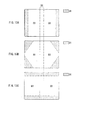
FIG. 9 . Here,FIGs. 10A and 10B each illustrate an enlarged view of a vicinity of the boundary between the regions. It is to be noted that,FIG. 10A is a sectional view taken along line I-I ofFIG. 8 , andFIG. 10B is a sectional view taken along line II-II ofFIG. 8 . As illustrated inFIG. 10A , in the second region D2, the thickness t2 thereof is smaller than the thickness t3 of the third region D3 adjacent to the second region D2 (t2<t3), and the thickness continuously (successively) varies from the second region D2 toward the third region D3. On the other hand, as illustrated inFIG. 10B , in the first region D1, the thickness t1 is smaller than the thickness t3 of the third region D3 adjacent to the first region D1 (t1<t3), and the thickness continuously (successively) varies from the third region D3 toward the first region D1. For example, the thicknesses t1 to t3 are preferably set such that the thickness varies in a range smaller than several tens of millimeters, for example. The width S1 of the first region D1 is set at several millimeters or more, specifically about 50 mm for example. - As described above, while keeping a stepless and smooth curved form or planar form, the supporting
substrate 10 has a structure in which the thickness is locally reduced in the first region D1 and the second region D2. It is to be noted that, in each of the first region D1, the second region D2, and the third region D3, the thickness may be gradually varied, or may be kept at a predetermined thickness. - It should be noted however that, more desirably, in the first region D1, a taper e1 whose thickness is reduced toward the edge is formed in a region D1e in the vicinity of the edge, as illustrated in
FIG. 10B . The width S1e of the region D1e is about several millimeters or less, for example. - The supporting
substrate 10 having the above-mentioned thickness variation is integrally formed with use of a thermoplastic elastomer or a heat-curable elastomer, for example. Examples of the elastomer include various kinds of resin materials based on urethane, styrene, olefin, ester, amide, silicone, or fluorine. Of these elastomers, in the case where a thermoplastic elastomer is used, it is possible to readily form the above-mentioned supportingsubstrate 10 by an injection molding method, for example. - Referring to
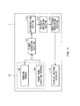
FIG. 11 , a functional configuration of theelectronic book 1 will be described. Theelectronic book 1 includes asignal acquiring section 111, adetermination section 112, adisplay switching section 113, and an imagesignal processing section 114. Thesignal acquiring section 111 is connected to thelocation sensor 16a and the bendingsensor 16b provided as components. - The
signal acquiring section 111. acquires a signal representing two-dimensional location information detected by thelocation sensor 16a. Thesignal acquiring section 111 also acquires a signal representing bend information (in a Z direction) detected by the bendingsensor 16b. - The
determination section 112 determines whether theelectronic book 1 is bent at a local portion, based on a result of a detection by the sensors. - The
display switching section 113 switches display content of thedisplay section 15, based on a result of a detection by the sensors. Specifically, when thedetermination section 112 determines that a predetermined region of theelectronic book 1 is bent, thedisplay switching section 113 allows thedisplay section 15 to display an image representing page turning (page flipping), scrolling, or the like. - The image
signal processing section 114 generates an image (image signal) to be displayed on thedisplay section 15. For example, theelectronic book 1 displays a desired page of content downloaded through a network on thedisplay section 15. - It is to be noted that, the function of each of the
signal acquiring section 111, thedetermination section 112, thedisplay switching section 113, and the imagesignal processing section 114 is realized by a dedicated control device or a processor (CPU) not shown in the figure configured to implement a program. A program and data representing a procedure to be implemented by a processor are stored in a hardware resource including storage devices such as a random access memory (RAM), a read only memory (ROM), and a hard disk drive (HDD). - Since, in the
electronic book 1, each of the supportingsubstrate 10, thelaminated body 11, thecover 13, and theprotect sheet 14 is made of a flexible material (has flexibility), and thespine 1a is provided with thepredetermine hinge section 12, a user is allowed to open and close theelectronic book 1 in the same manner as handling a real paper book. For example, in a state where theelectronic book 1 is opened as illustrated inFIG. 1A , when an image (an image of one page of a book for example) is displayed on thedisplay section 15, a user is allowed to read the page while holding theelectronic book 1 with one hand or both hands, or while opening (putting) theelectronic book 1 on a stand or the like. - As described above, in a state where certain content is displayed on the
display section 15, when a user performs a predetermined action associated with a variation in the physical form of theelectronic book 1, such an action is detected by thedetection section 16, and thedisplay switching section 113 switches display content. Specifically, in the case where thedetection section 16 detects local deflection (bending (including torsion, pushingly moving, and the like)) of the supporting substrate 10 (the electronic book 1), thedisplay switching section 113 switches display content, and displays content representing, for example, a page turning action or a scroll action. In other words, an inputting operation (such as a page turning action and a scroll action) by a user is perceived, and content corresponding to the perceived action is displayed (other page is displayed, other line is displayed, or the like). - Specifically, the
signal acquiring section 111 acquires XY position coordinate information from thelocation sensor 16a, and acquires, from the bendingsensor 16b, displacement in a Z direction as bend (deflection) information, and outputs the acquired information to thedetermination section 112. Thedetermination section 112 specifies a location (a location contacted by finger (s) or the like) in the XY plane where an inputting action is performed by a user, based on the acquired XY position coordinate information, and determines whether theelectronic book 1 is bent by the user, based on the acquired bend information. It is to be noted that, this determination is made by, for example, comparison with a threshold level of blending amount preliminarily held therein, and, for example, if the bending amount corresponding to the acquired bend information is smaller than the threshold level, then the determination result is "not being bent", whereas if the bending amount is greater than the threshold level, then the determination result is "being bent". In this way, inputting operations by a user as illustrated inFIGs. 12A to 12C are perceived. - In other words, it is possible to perceive an action A of bending an end region including corner portions and the like of the
electronic book 1 to a near side as illustrated inFIG. 12A . Likewise, it is also possible to perceive an action B of bending and twisting an end portion of theelectronic book 1 to a far side as illustrated inFIG. 12B , and an action C of moving and pushing (pushingly moving) an end portion of theelectronic book 1 as illustrated inFIG. 12C . Among them, for example, the actions illustrated inFIGs. 12A and 12B are actions generally performed when a page is turned (flipped). On the other hand, the action illustrated inFIG. 12C is one of actions generally performed when a user performs a scroll action. It is to be noted that, since the scroll operation entails movement in the XY plane, it is preferable to simultaneously determine whether the XY position coordinate is moving at the time of determining the bending state. It should be noted that, these actions are merely illustrative, and are representative examples of actions that are generally performed when a user turns (flips) a page of a book, or performs a scroll. - Then, if the user inputting operation perceived by the
detection section 16 is the page turning actions illustrated inFIGs. 12A and 12B for example, then thedisplay switching section 113 switches the display content to, for example, the content representing the previous page or the next page of the page that has been displayed. At this time, it is possible to perform a display in which a currently displayed page is instantly switched to the previous page or the next page on thedisplay section 15, or it is also possible to perform a simulated display for displaying a state in which content of the next page gradually becomes visible on a flipped part, as in the case of flipping a page of a real book. On the other hand, if the user inputting operation perceived by thedetection section 16 is the scroll action illustrated inFIG. 12C for example, then thedisplay switching section 113 switches the display content to, for example, content representing previous line (s) or next line (s) of a predetermined line (or paragraph) of a page that has been displayed. - As described above, a user is allowed to perform an operation such as page turning and scrolling by the action of locally bending the
electronic book 1. Specifically, since it is only necessary to operate theelectronic book 1 in a similar way to a book in real space, a correlation between an inputting operation and display content to be actually changed is high, and the inputting operation and the display content to be actually changed is easily and intuitively connected for a user. - In particular, in the present embodiment, the supporting
substrate 10 has a thickness variation, and locally-varied flexibility. Specifically, the first region D1 corresponding to the region on the edge side of the supportingsubstrate 10 is formed to be smaller in thickness than the third region D3 adjacent to the first region D1. With this configuration, at the time of the above-described inputting operation, a user is allowed to have a feeling of operation similar to a real book. In other words, when a user performs the actions of page turning, scrolling, and the like as illustrated inFIGs. 12A to 12C , since the first region D1 is formed to have a smaller thickness, it is easily bent like a page of a real paper. In addition, the higher flexibility increases the bending amount, and thus the detection sensitivity is improved. Consequently, when display content is switched based on a user operation associated with a variation in a physical form, excellent operability is realized. - In addition, at the portion corresponding to the
spine 1a of theelectronic book 1, the supportingsubstrate 10 is formed such that the second region D2 is smaller in thickness than the third region D3 adjacent to the second region D2, and further, the supportingsubstrate 10 is formed to have a curved shape matching the curved shape of thehinge section 12. This configuration allows a smooth opening/closing operation of theelectronic book 1 while covering thehinge section 12 to maintain a design property. - Further, in the vicinity of the boundaries between the first region D1, the second region D2, and the third region D3 of the supporting
substrate 10, there is no step, and the thickness thereof is continuously (successively) varied. Therefore, a smooth curved surface or plane is formed in whole, and thus it is possible to realize a form which is beautiful in terms of design and attains emotional attachment of a user. - Additionally, in the first region D1 of the supporting
substrate 10, the taper e1 having an inclination in which the thickness is reduced toward the edge is provided in the vicinity of the edge, and thus it is possible to form an edge portion with a very small thickness. It is to be noted that, since the vicinity of the edge as mentioned above is typically not formed with a laminated body including thedisplay section 15 and the like (or is exposed from the laminated body), there is no major problem even if it is formed to have a very small thickness. By making the edge portion of the supportingsubstrate 10 ultra-thin, a thickness closer to that of a paper is obtained, thereby improving operability. - As described hereinabove, since, in the present embodiment, the supporting
substrate 10 has flexibility, and in the first region D1 on the end portion side in the plane thereof, the thickness thereof is gradually decreased toward the edge, a user is allowed to readily bend and twist a local portion on the end portion side of the wholeelectronic book 1. Consequently, when display content is switched based on a user operation associated with a variation in a physical form, excellent operability is realized. - It is to be noted that, in the above-mentioned embodiment, the supporting
substrate 10 is segmented into three regions in order to describe the thickness variation, the three regions are not limited to the above-described regions. For example, as illustrated inFIG. 13A , the first region D1 may be only regions along two short sides of the rectangular form, or as illustrated inFIG. 13B , may be regions corresponding to four corner portions of the rectangular form. Alternatively, as illustrated inFIG. 13C , the first region D1 may be only regions along two long sides of the rectangular form (except for the portion corresponding to the second region D2). It is to be noted that, although not shown in the figures, the first region D1 may not necessarily be provided symmetrically. In the case where the part to be used by a user for an inputting operation is specified in advance, it suffices to locally reduce the thickness of that part only as the first region D1. - Hereinabove, while description has been made based on the embodiment and the modification, the content of the present disclosure is not limited to the embodiment and so forth, and various modifications may be made. For example, while, in the above-mentioned embodiment and so forth, a configuration in which the thickness of the supporting
substrate 10 is varied in the plane thereof is exemplified, if a configuration in which flexibility is varied in the plane thereof is secured, the thickness variation may be unnecessary. For example, by forming a supporting substrate with use of a material whose hardness varies from region to region, it is possible to obtain an effect substantially similar to that of the above-mentioned embodiment. - In addition, while, in the above-mentioned embodiment and so forth, a case in which the planar form of the supporting
substrate 10 is rectangular is exemplified, the planar form of the supportingsubstrate 10 is not limited thereto, other forms such as a square form or other polygonal forms, a circular form, and an elliptical form may also be adopted. - Further, while, in the above-mentioned embodiment and so forth, a case in which the region corresponding to the
spine 1a of the electronic book 1 (the second region D2 of the supporting substrate 10) is extendedly formed so as to bisect the supportingsubstrate 10 is exemplified, the form of the second region D2 is not limited thereto. For example, the second region D2 may be formed to extend to either a region closer to the right side or left side of the supportingsubstrate 10. In other words, such a configuration that one side of the supporting substrate is exposed from the other side in a folded state may also be adopted. In addition, the number of the second region D2 is not limited to one, and may be plural. - Additionally, while, in the above-mentioned embodiment and so forth, an electronic book is described as an example of the display or the electronic unit of the embodiment of present disclosure, the display or the electronic unit of the embodiment of the present disclosure may also be employed in other electronic units such as various kinds of mobile units (note type personal computers (PCs), mobile audio players, mobile phones, personal digital assistants (PDAs), and the like). In addition, the display or the electronic unit of the embodiment of the present disclosure may be used not only as a book reader, but also as any of other displays and electronic units with which a music player, a movie player, a picture viewer, a map application, a web browser, or the like may be browsed.
- In addition, while the hinge section attached to a part of the supporting substrate is provided to the
electronic book 1 so that theelectronic book 1 is foldable, it is not absolutely necessary to provide thehinge section 12. If the supportingsubstrate 10 is so formed that the thickness thereof is locally reduced in the second region D2, then the second region D2 is readily bent compared to other portions, and therefore it is possible to open and close the electronic book with the second region serving as the spine portion thereof. It should be noted, however, that, the opening/closing action may be more smoothly performed when thehinge section 12 is adopted. - Further, the supporting substrate of the embodiment of the present disclosure does not necessarily need to be foldable, and as illustrated in
FIG. 14A for example, a display or an electronic unit of so-called tablet-type in which the supportingsubstrate 10 is formed in a single plate form is also applicable. In this case, it is only necessary to form a structure in which the thickness of at least a part of an end portion is reduced relative to that of a center portion. In addition, as illustrated inFIG. 14B for example, the supportingsubstrate 10 may also be formed in a band shape attachable to arm or the like, and in this case, it is only necessary that, for example, an image is displayed on a side face thereof, and the thickness of both end portions in the width direction of the supportingsubstrate 10 is reduced (see a sectional view taken along line I-I). With this structure, when an inputting operation is performed in such a manner that both ends in the width direction of the supportingsubstrate 10 are held (pinched) by fingers, operability is improved. Further, although not shown in the figures, the above-described foldable, or tablet-type display or electronic unit may also be configured in such a manner that other units such as a keyboard may be connected thereto. - It is to be noted that the display and the electronic unit according to the embodiments of the present disclosure may be configured as described in the following (1) to (18).
- (1) A display including:
- a supporting substrate having flexibility; and
- a display section provided on the supporting substrate, wherein
- the flexibility of the supporting substrate gradually increases toward an edge in a first region provided at at least a portion on a side of the edge in a plane thereof.
- (2) The display according to (1), wherein, in the first region, a thickness of the supporting substrate gradually decreases toward the edge.
- (3) The display according to (1) or (2), wherein
the supporting substrate is foldable in whole when the supporting substrate is folded in a second region, the second region extending in one direction and dividing the plane, and
the second region is smaller in thickness than a nearby region thereof. - (4) The display according to (3), wherein
the supporting substrate includes a third region between the first region and the second region,
in a vicinity of a boundary between the second region and the third region, the thickness of the supporting substrate gradually increases from the second region toward the third region, and
in a vicinity of a boundary between the third region and the first region, the thickness of the supporting substrate gradually decreases from the third region toward the first region. - (5) The display according to any one of (1) to (4), wherein the supporting substrate includes, in a vicinity of the edge in the first region thereof, a taper whose thickness is decreased toward the edge to form an inclination.
- (6) The display according to (3) or (4), further including a hinge section in contact with the second region of the supporting substrate.
- (7) The display according to (6), wherein
the hinge section has a curved shape curved at a constant curvature regardless of an folding angle of the supporting substrate, and
the supporting substrate is formed to have a curved shape corresponding to the curved shape of the hinge section in the second region. - (8) The display according to any one of (1) to (7), wherein the supporting substrate is integrally formed.
- (9) The display according to (8), wherein the supporting substrate is made of an elastomer.
- (10) The display according to any one of (1) to (9), wherein
the supporting substrate has a planar form of a square form, and
the first region is a region corresponding to one or more sides of the square form. - (11) The display according to any one of (1) to (10), wherein
the supporting substrate has a planar form of a square form, and
the first region is a region corresponding to one or more corner portions of the square form. - (12) The display according to any one of (3), (4), and (6), wherein
the supporting substrate has a planar form of a square form, and
the second region is a region which is extendedly formed to bisect the square form. - (13) The display according to any one of (1) to (12), further including a detection section laminated on the supporting substrate together with the display section and configured to detect a local deflection of the supporting substrate.
- (14) The display according to (13), further including a display switching section configured to switch content displayed on the display section, based on a result of a detection by the detection section, wherein the display switching section performs an image display corresponding to page turning or scrolling on the display section when the detection section has detected a deflection in the first region of the supporting substrate.
- (15) The display according to any one of (1) to (14), wherein the display section includes an organic electroluminescence device, a liquid crystal device, or an electrophoretic device.
- (16) The display according to any one of (1) to (15), further including an organic thin film transistor as a drive device of the display section on the supporting substrate.
- (17) An electronic unit with a display, the display including:
- a supporting substrate having flexibility; and
- a display section provided on the supporting substrate, wherein
- the flexibility of the supporting substrate gradually increases toward an edge in a first region provided at at least a portion on a side of the edge in a plane thereof.
- (18) A supporting substrate configured to support a display section and having flexibility, the flexibility of the supporting substrate gradually increasing toward an edge in a first region provided at at least a portion on a side of the edge in a plane thereof.
- In some embodiments:
- the supporting substrate is integrally formed;
- wherein the display section includes an organic electroluminescence device, a liquid crystal device, or an electrophoretic device; and
- the display comprises an organic thin film transistor as a drive device of the display section on the supporting substrate.
- The present disclosure contains subject matter related to that disclosed in Japanese Priority Patent Application
JP 2011-205986 - It should be understood by those skilled in the art that various modifications, combinations, subcombinations, and alterations may occur depending on design requirements and other factors insofar as they are within the scope of the appended claims or the equivalents thereof.
Claims (15)
- A display comprising:a supporting substrate having flexibility; anda display section provided on the supporting substrate, whereinthe flexibility of the supporting substrate gradually increases toward an edge in a first region provided at at least a portion on a side of the edge in a plane thereof.
- The display according to, claim 1, wherein, in the first region, a thickness of the supporting substrate gradually decreases toward the edge.
- The display according to claim 2, wherein
the supporting substrate is foldable in whole when the supporting substrate is folded in a second region, the second region extending in one direction and dividing the plane, and
the second region is smaller in thickness than a nearby region thereof. - The display according to claim 3, wherein
the supporting substrate includes a third region between the first region and the second region,
in a vicinity of a boundary between the second region and the third region, the thickness of the supporting substrate gradually increases from the second region toward the third region, and
in a vicinity of a boundary between the third region and the first region, the thickness of the supporting substrate gradually decreases from the third region toward the first region. - The display according to claim 1, wherein the supporting substrate includes, in a vicinity of the edge in the first region thereof, a taper whose thickness is decreased toward the edge to form an inclination.
- The display according to claim 3, further comprising a hinge section in contact with the second region of the supporting substrate.
- The display according to claim 6, wherein
the hinge section has a curved shape curved at a constant curvature regardless of an folding angle of the supporting substrate, and
the supporting substrate is formed to have a curved shape corresponding to the curved shape of the hinge section in the second region. - The display according to claim 1, wherein the supporting substrate is made of an elastomer.
- The display according to claim 1, wherein
the supporting substrate has a planar form of a square form, and
the first region is a region corresponding to one or more sides of the square form. - The display according to claim 1, wherein
the supporting substrate has a planar form of a square form, and
the first region is a region corresponding to one or more corner portions of the square form. - The display according to claim 3, wherein
the supporting substrate has a planar form of a square form, and
the second region is a region which is extendedly formed to bisect the square form. - The display according to claim 1, further comprising a detection section laminated on the supporting substrate together with the display section and configured to detect a local deflection of the supporting substrate.
- The display according to claim 12, further comprising a display switching section configured to switch content displayed on the display section, based on a result of a detection by the detection section, wherein
the display switching section performs an image display corresponding to page turning or scrolling on the display section when the detection section has detected a deflection in the first region of the supporting substrate. - An electronic unit with a display, the display comprising:a supporting substrate having flexibility; anda display section provided on the supporting substrate, whereinthe flexibility of the supporting substrate gradually increases toward an edge in a first region provided at at least a portion on a side of the edge in a plane thereof.
- A supporting substrate configured to support a display section and having flexibility, the flexibility of the supporting substrate gradually increasing toward an edge in a first region provided at at least a portion on a side of the edge in a plane thereof.
Applications Claiming Priority (1)
| Application Number | Priority Date | Filing Date | Title |
|---|---|---|---|
| JP2011205986A JP5887790B2 (en) | 2011-09-21 | 2011-09-21 | Display device and electronic device |
Publications (1)
| Publication Number | Publication Date |
|---|---|
| EP2573644A2 true EP2573644A2 (en) | 2013-03-27 |
Family
ID=46934414
Family Applications (1)
| Application Number | Title | Priority Date | Filing Date |
|---|---|---|---|
| EP20120180704 Withdrawn EP2573644A2 (en) | 2011-09-21 | 2012-08-16 | Display, electronic unit, and supporting substrate |
Country Status (5)
| Country | Link |
|---|---|
| US (1) | US9013884B2 (en) |
| EP (1) | EP2573644A2 (en) |
| JP (1) | JP5887790B2 (en) |
| CN (2) | CN202887612U (en) |
| BR (1) | BR102012023277A2 (en) |
Cited By (10)
| Publication number | Priority date | Publication date | Assignee | Title |
|---|---|---|---|---|
| GB2517782A (en) * | 2013-09-02 | 2015-03-04 | Nokia Technologies Oy | An apparatus and method of providing an apparatus comprising a bendable portion |
| GB2520271A (en) * | 2013-11-13 | 2015-05-20 | Nokia Corp | An apparatus and method of providing an apparatus comprising a bendable portion |
| EP3015947A1 (en) * | 2014-10-27 | 2016-05-04 | LG Electronics Inc. | Hinge section for foldable portable electronic device |
| CN105900037A (en) * | 2014-01-29 | 2016-08-24 | 惠普发展公司,有限责任合伙企业 | Electronic device with flexible display |
| US9719665B2 (en) | 2013-07-12 | 2017-08-01 | Semiconductor Energy Laboratory Co., Ltd. | Light-emitting device |
| EP3177980A4 (en) * | 2014-08-09 | 2018-04-11 | Google LLC | Detecting a state of a wearable device |
| WO2018194605A1 (en) * | 2017-04-20 | 2018-10-25 | Hewlett-Packard Development Company, L.P. | Foldable hinge for electronic devices |
| US11004925B2 (en) | 2013-12-02 | 2021-05-11 | Semiconductor Energy Laboratory Co., Ltd. | Display device and method for manufacturing the same |
| US11322700B2 (en) | 2014-10-28 | 2022-05-03 | Semiconductor Energy Laboratory Co., Ltd. | Light-emitting device having light blocking layer overlapping non-light emitting region |
| US11360590B2 (en) | 2014-10-10 | 2022-06-14 | Semiconductor Energy Laboratory Co., Ltd. | Functional panel, device, and data processor |
Families Citing this family (53)
| Publication number | Priority date | Publication date | Assignee | Title |
|---|---|---|---|---|
| JP5887790B2 (en) * | 2011-09-21 | 2016-03-16 | ソニー株式会社 | Display device and electronic device |
| KR101386220B1 (en) * | 2012-06-26 | 2014-04-17 | 삼성디스플레이 주식회사 | A flexible display device |
| KR102020659B1 (en) | 2013-06-03 | 2019-09-11 | 삼성디스플레이 주식회사 | Foldable display device |
| US9356049B2 (en) * | 2013-07-26 | 2016-05-31 | Semiconductor Energy Laboratory Co., Ltd. | Display device with a transistor on an outer side of a bent portion |
| TWI688850B (en) | 2013-08-13 | 2020-03-21 | 飛利斯有限公司 | Article with electronic display |
| WO2015031501A1 (en) | 2013-08-27 | 2015-03-05 | Polyera Corporation | Attachable device having a flexible electronic component |
| WO2015031426A1 (en) | 2013-08-27 | 2015-03-05 | Polyera Corporation | Flexible display and detection of flex state |
| WO2015038684A1 (en) | 2013-09-10 | 2015-03-19 | Polyera Corporation | Attachable article with signaling, split display and messaging features |
| KR102091030B1 (en) * | 2013-10-18 | 2020-03-19 | 삼성디스플레이 주식회사 | Display apparatus |
| JP6228813B2 (en) * | 2013-10-31 | 2017-11-08 | 日本電産サンキョー株式会社 | Optical device |
| CN106030688B (en) | 2013-12-24 | 2020-01-24 | 飞利斯有限公司 | Flexible electronic article |
| CN106030687B (en) | 2013-12-24 | 2020-08-14 | 飞利斯有限公司 | Dynamically flexible article |
| JP6639400B2 (en) | 2013-12-24 | 2020-02-05 | フレックステラ, インコーポレイテッドFlexterra, Inc. | Support structure for attachable two-dimensional flexible electronic device |
| WO2015100224A1 (en) | 2013-12-24 | 2015-07-02 | Polyera Corporation | Flexible electronic display with user interface based on sensed movements |
| US20150227245A1 (en) | 2014-02-10 | 2015-08-13 | Polyera Corporation | Attachable Device with Flexible Electronic Display Orientation Detection |
| TWI654736B (en) | 2014-02-14 | 2019-03-21 | 日商半導體能源研究所股份有限公司 | Illuminating device |
| KR102435833B1 (en) | 2014-02-28 | 2022-08-24 | 가부시키가이샤 한도오따이 에네루기 켄큐쇼 | Electronic device |
| US9588549B2 (en) * | 2014-02-28 | 2017-03-07 | Semiconductor Energy Laboratory Co., Ltd. | Electronic device |
| EP3872599A1 (en) | 2014-05-23 | 2021-09-01 | Samsung Electronics Co., Ltd. | Foldable device and method of controlling the same |
| TWI692272B (en) | 2014-05-28 | 2020-04-21 | 美商飛利斯有限公司 | Device with flexible electronic components on multiple surfaces |
| USD769209S1 (en) * | 2014-05-30 | 2016-10-18 | Lg Electronics Inc. | Cellular phone |
| USD788726S1 (en) * | 2014-06-09 | 2017-06-06 | Lg Electronics Inc. | Cellular phone |
| KR102290479B1 (en) * | 2014-08-13 | 2021-08-18 | 삼성디스플레이 주식회사 | Display Device |
| WO2016043136A1 (en) * | 2014-09-19 | 2016-03-24 | 日本電気株式会社 | Display device and production method for same |
| KR102338003B1 (en) * | 2014-10-07 | 2021-12-10 | 삼성전자 주식회사 | Electronic device comprising a flexible display |
| KR102343141B1 (en) * | 2014-12-19 | 2021-12-27 | 삼성디스플레이 주식회사 | Device using stretchable display and controlling method of the same |
| JP6287814B2 (en) * | 2014-12-24 | 2018-03-07 | ブラザー工業株式会社 | Cover for information terminal |
| CN105988509A (en) * | 2015-02-02 | 2016-10-05 | 联想(北京)有限公司 | Laptop computer |
| CN107210011B (en) * | 2015-02-04 | 2019-09-03 | 夏普株式会社 | Display device and its manufacturing method |
| US10317934B2 (en) * | 2015-02-04 | 2019-06-11 | Dell Products, Lp | Gearing solution for an external flexible substrate on a multi-use product |
| WO2016138356A1 (en) | 2015-02-26 | 2016-09-01 | Polyera Corporation | Attachable device having a flexible electronic component |
| JP6512632B2 (en) * | 2015-03-20 | 2019-05-15 | デクセリアルズ株式会社 | ANISOTROPY CONNECTED STRUCTURE AND METHOD FOR MANUFACTURING ANISOTROPY CONNECTED STRUCTURE |
| KR102414855B1 (en) * | 2015-04-30 | 2022-07-01 | 삼성전자주식회사 | Flexible electronic device |
| CN107548478B (en) * | 2015-05-04 | 2020-08-11 | 惠普发展公司,有限责任合伙企业 | Hinge for foldable parts |
| US10073496B2 (en) | 2015-06-26 | 2018-09-11 | Hewlett-Packard Development Company, L.P. | Hinge for a foldable display unit |
| CN106325374A (en) * | 2015-06-30 | 2017-01-11 | 联想(北京)有限公司 | Electronic equipment and display processing method |
| CN106325373A (en) * | 2015-06-30 | 2017-01-11 | 联想(北京)有限公司 | Electronic equipment and information processing method |
| US9557772B1 (en) * | 2015-07-21 | 2017-01-31 | Lenovo (Beijing) Co., Ltd. | Electronic device |
| US10871803B2 (en) * | 2016-04-29 | 2020-12-22 | Hewlett-Packard Development Company, L.P. | Flexible structures |
| USD822658S1 (en) | 2016-06-30 | 2018-07-10 | Intel Corporation | Computer notebook |
| US9869114B1 (en) | 2016-08-05 | 2018-01-16 | Shin Zu Shing Co., Ltd. | Hinge assembly for electronic device |
| US10394274B2 (en) * | 2016-08-31 | 2019-08-27 | Microsoft Technology Licensing, Llc | Flexible electronic display devices |
| JP2018081186A (en) * | 2016-11-16 | 2018-05-24 | 株式会社半導体エネルギー研究所 | Information processor, display device, and electronic apparatus |
| TWI612207B (en) * | 2017-04-25 | 2018-01-21 | 華碩電腦股份有限公司 | Hinge assembly and electronic device using the same |
| USD883943S1 (en) * | 2018-01-31 | 2020-05-12 | Samsung Display Co., Ltd. | Display device |
| KR102583233B1 (en) * | 2018-02-12 | 2023-09-26 | 삼성디스플레이 주식회사 | Foldable display device |
| JPWO2019187735A1 (en) * | 2018-03-29 | 2021-04-15 | ソニー株式会社 | Display device |
| US10817030B2 (en) | 2019-01-14 | 2020-10-27 | Dell Products L.P. | Portable information handling system flexible display with alternating slide support frame |
| US10928863B2 (en) * | 2019-01-14 | 2021-02-23 | Dell Products L.P. | Portable information handling system midframe to sliding frame assembly |
| KR102136826B1 (en) * | 2019-09-04 | 2020-07-23 | 삼성디스플레이 주식회사 | Foldable display device |
| JP7243565B2 (en) * | 2019-10-17 | 2023-03-22 | 株式会社デンソー | Flexible display device |
| CN111811559A (en) * | 2020-08-31 | 2020-10-23 | 京东方科技集团股份有限公司 | Support device for flexible plate-like structures |
| CN113284422B (en) * | 2021-06-10 | 2023-07-25 | 维沃移动通信有限公司 | Electronic equipment |
Citations (3)
| Publication number | Priority date | Publication date | Assignee | Title |
|---|---|---|---|---|
| JP2010157060A (en) | 2008-12-26 | 2010-07-15 | Sony Corp | Display device |
| JP2010218102A (en) | 2009-03-16 | 2010-09-30 | Sony Corp | Electronic equipment |
| JP2011205986A (en) | 2010-03-30 | 2011-10-20 | Nippon Shokubai Co Ltd | Method for producing optically active mandelic acid derivative |
Family Cites Families (18)
| Publication number | Priority date | Publication date | Assignee | Title |
|---|---|---|---|---|
| DE19741453A1 (en) * | 1997-09-19 | 1999-03-25 | Packing Gmbh Agentur Fuer Desi | Digital book, esp. for reproducing textual information |
| JP4115818B2 (en) * | 2002-12-03 | 2008-07-09 | 富士フイルム株式会社 | Display device and display device control method |
| TWI233771B (en) * | 2002-12-13 | 2005-06-01 | Victor Company Of Japan | Flexible rigid printed circuit board and method of fabricating the board |
| JP3816457B2 (en) * | 2003-03-18 | 2006-08-30 | 株式会社東芝 | Display device |
| JP2006072115A (en) * | 2004-09-03 | 2006-03-16 | Fuji Photo Film Co Ltd | Image display device |
| JP2006092809A (en) * | 2004-09-21 | 2006-04-06 | Victor Co Of Japan Ltd | Sheet display |
| JP4739858B2 (en) * | 2005-08-12 | 2011-08-03 | 株式会社リコー | Display device, control device, information processing device, display control method, and display control program |
| JP5167624B2 (en) * | 2005-12-28 | 2013-03-21 | セイコーエプソン株式会社 | Electrophoretic display device and electronic apparatus |
| GB0702350D0 (en) * | 2007-02-07 | 2007-03-21 | Plastic Logic Ltd | Electronic reading devices |
| JP2011027814A (en) * | 2009-07-22 | 2011-02-10 | Seiko Epson Corp | Electrooptical device and electronic equipment |
| GB2524419B (en) * | 2009-10-23 | 2015-10-28 | Flexenable Ltd | Electronic document reading devices |
| US8759687B2 (en) * | 2010-02-12 | 2014-06-24 | Ibiden Co., Ltd. | Flex-rigid wiring board and method for manufacturing the same |
| JP5887790B2 (en) * | 2011-09-21 | 2016-03-16 | ソニー株式会社 | Display device and electronic device |
| US8837126B2 (en) * | 2012-02-28 | 2014-09-16 | Lg Electronics Inc. | Display device |
| KR101911047B1 (en) * | 2012-07-25 | 2018-10-24 | 삼성디스플레이 주식회사 | Case and display device |
| US8952911B2 (en) * | 2012-08-08 | 2015-02-10 | Creator Technology B.V. | Electronic device with a touch sensitive panel, method for operating the electronic device, and display system |
| KR102215080B1 (en) * | 2012-09-17 | 2021-02-10 | 삼성전자주식회사 | Flexible display apparatus and flexible display apparatus controlling method |
| KR102145533B1 (en) * | 2012-10-04 | 2020-08-18 | 삼성전자주식회사 | Flexible display apparatus and control method thereof |
-
2011
- 2011-09-21 JP JP2011205986A patent/JP5887790B2/en not_active Expired - Fee Related
-
2012
- 2012-08-16 EP EP20120180704 patent/EP2573644A2/en not_active Withdrawn
- 2012-09-10 US US13/608,028 patent/US9013884B2/en not_active Expired - Fee Related
- 2012-09-14 CN CN2012204776751U patent/CN202887612U/en not_active Expired - Fee Related
- 2012-09-14 BR BRBR102012023277-4A patent/BR102012023277A2/en not_active Application Discontinuation
- 2012-09-14 CN CN201210348966.5A patent/CN103021277B/en not_active Expired - Fee Related
Patent Citations (3)
| Publication number | Priority date | Publication date | Assignee | Title |
|---|---|---|---|---|
| JP2010157060A (en) | 2008-12-26 | 2010-07-15 | Sony Corp | Display device |
| JP2010218102A (en) | 2009-03-16 | 2010-09-30 | Sony Corp | Electronic equipment |
| JP2011205986A (en) | 2010-03-30 | 2011-10-20 | Nippon Shokubai Co Ltd | Method for producing optically active mandelic acid derivative |
Cited By (27)
| Publication number | Priority date | Publication date | Assignee | Title |
|---|---|---|---|---|
| US11143387B2 (en) | 2013-02-12 | 2021-10-12 | Semiconductor Energy Laboratory Co., Ltd. | Light-emitting device |
| US9719665B2 (en) | 2013-07-12 | 2017-08-01 | Semiconductor Energy Laboratory Co., Ltd. | Light-emitting device |
| US11639785B2 (en) | 2013-07-12 | 2023-05-02 | Semiconductor Energy Laboratory Co., Ltd. | Light-emitting device |
| US11371678B2 (en) | 2013-07-12 | 2022-06-28 | Semiconductor Energy Laboratory Co., Ltd. | Light-emitting device |
| US10119683B2 (en) | 2013-07-12 | 2018-11-06 | Semiconductor Energy Laboratory Co., Ltd. | Light-emitting device |
| US10125955B2 (en) | 2013-07-12 | 2018-11-13 | Semiconductor Energy Laboratory Co., Ltd. | Light-emitting device |
| US10711980B2 (en) | 2013-07-12 | 2020-07-14 | Semiconductor Energy Laboratory Co., Ltd. | Light-emitting device |
| GB2517782B (en) * | 2013-09-02 | 2020-08-19 | Nokia Technologies Oy | An apparatus and method of providing an apparatus comprising a bendable portion |
| GB2517782A (en) * | 2013-09-02 | 2015-03-04 | Nokia Technologies Oy | An apparatus and method of providing an apparatus comprising a bendable portion |
| US9506279B2 (en) | 2013-11-13 | 2016-11-29 | Nokia Technologies Oy | Apparatus and method of providing an apparatus comprising a bendable portion |
| GB2520271A (en) * | 2013-11-13 | 2015-05-20 | Nokia Corp | An apparatus and method of providing an apparatus comprising a bendable portion |
| USRE47619E1 (en) | 2013-11-13 | 2019-09-24 | Nokia Technologies Oy | Apparatus and method of providing an apparatus comprising a bendable portion |
| US11672148B2 (en) | 2013-12-02 | 2023-06-06 | Semiconductor Energy Laboratory Co., Ltd. | Display device and method for manufacturing the same |
| US11004925B2 (en) | 2013-12-02 | 2021-05-11 | Semiconductor Energy Laboratory Co., Ltd. | Display device and method for manufacturing the same |
| CN105900037B (en) * | 2014-01-29 | 2020-03-17 | 惠普发展公司,有限责任合伙企业 | Electronic device with flexible display |
| CN105900037A (en) * | 2014-01-29 | 2016-08-24 | 惠普发展公司,有限责任合伙企业 | Electronic device with flexible display |
| EP3177980A4 (en) * | 2014-08-09 | 2018-04-11 | Google LLC | Detecting a state of a wearable device |
| US11360590B2 (en) | 2014-10-10 | 2022-06-14 | Semiconductor Energy Laboratory Co., Ltd. | Functional panel, device, and data processor |
| US9625947B2 (en) | 2014-10-27 | 2017-04-18 | Lg Electronics Inc. | Portable electronic device |
| EP3015947A1 (en) * | 2014-10-27 | 2016-05-04 | LG Electronics Inc. | Hinge section for foldable portable electronic device |
| US11322700B2 (en) | 2014-10-28 | 2022-05-03 | Semiconductor Energy Laboratory Co., Ltd. | Light-emitting device having light blocking layer overlapping non-light emitting region |
| US11380860B2 (en) | 2014-10-28 | 2022-07-05 | Semiconductor Energy Laboratory Co., Ltd. | Foldable light-emitting device having trapezoid spacer |
| US11393995B2 (en) | 2014-10-28 | 2022-07-19 | Semiconductor Energy Laboratory Co., Ltd. | Light-emitting device having light blocking overlapping connection portion or spacer |
| US11476431B2 (en) | 2014-10-28 | 2022-10-18 | Semiconductor Energy Laboratory Co., Ltd. | Foldable electronic device having an elastic body in openings of the spacers |
| US11785835B2 (en) | 2014-10-28 | 2023-10-10 | Semiconductor Energy Laboratory Co., Ltd. | Touch panel having a photoelectric conversion element between the first and second flexible substrates |
| WO2018194605A1 (en) * | 2017-04-20 | 2018-10-25 | Hewlett-Packard Development Company, L.P. | Foldable hinge for electronic devices |
| US11553612B2 (en) | 2017-04-20 | 2023-01-10 | Hewlett-Packard Development Company, L.P. | Foldable hinge for electronic devices |
Also Published As
| Publication number | Publication date |
|---|---|
| BR102012023277A2 (en) | 2013-11-12 |
| US9013884B2 (en) | 2015-04-21 |
| CN103021277A (en) | 2013-04-03 |
| JP2013068719A (en) | 2013-04-18 |
| JP5887790B2 (en) | 2016-03-16 |
| CN202887612U (en) | 2013-04-17 |
| US20130070431A1 (en) | 2013-03-21 |
| CN103021277B (en) | 2017-05-17 |
Similar Documents
| Publication | Publication Date | Title |
|---|---|---|
| US9013884B2 (en) | Display, electronic unit, and supporting substrate | |
| US20150138103A1 (en) | Flexible display unit and electronic apparatus | |
| US10627868B2 (en) | Flexible device | |
| US20130258565A1 (en) | Display unit and electronic apparatus | |
| US20190073035A1 (en) | Haptic feedback for interactions with foldable-bendable displays | |
| US11343908B2 (en) | Display unit and electronic apparatus | |
| US9164547B1 (en) | Foldable display apparatus | |
| RU2494440C2 (en) | Electronic device with rotary panels arranged for display and adaptive interface | |
| US9304949B2 (en) | Sensing user input at display area edge | |
| US20050062715A1 (en) | Information processing apparatus having function of changing orientation of screen image | |
| US20120075236A1 (en) | Terminal with touch screen | |
| US11886255B2 (en) | Foldable display device with movable support body | |
| Wightman et al. | Bendflip: examining input techniques for electronic book readers with flexible form factors | |
| KR20150060278A (en) | Multistage folding display apparatus and function controlling method thereof | |
| EP3356920B1 (en) | Electronic device for displaying multiple screens and control method therefor | |
| CN110858088B (en) | Portable electronic device and method for controlling picture of display module | |
| KR20150094873A (en) | Portable device | |
| JP6830130B2 (en) | Electronics |
Legal Events
| Date | Code | Title | Description |
|---|---|---|---|
| PUAI | Public reference made under article 153(3) epc to a published international application that has entered the european phase |
Free format text: ORIGINAL CODE: 0009012 |
|
| 17P | Request for examination filed |
Effective date: 20120816 |
|
| AK | Designated contracting states |
Kind code of ref document: A2 Designated state(s): AL AT BE BG CH CY CZ DE DK EE ES FI FR GB GR HR HU IE IS IT LI LT LU LV MC MK MT NL NO PL PT RO RS SE SI SK SM TR |
|
| AX | Request for extension of the european patent |
Extension state: BA ME |
|
| STAA | Information on the status of an ep patent application or granted ep patent |
Free format text: STATUS: THE APPLICATION HAS BEEN WITHDRAWN |
|
| 18W | Application withdrawn |
Effective date: 20150108 |