EP2573527A1 - Automatic patient weight measurement for determining pressure relief set points - Google Patents
Automatic patient weight measurement for determining pressure relief set points Download PDFInfo
- Publication number
- EP2573527A1 EP2573527A1 EP12185378A EP12185378A EP2573527A1 EP 2573527 A1 EP2573527 A1 EP 2573527A1 EP 12185378 A EP12185378 A EP 12185378A EP 12185378 A EP12185378 A EP 12185378A EP 2573527 A1 EP2573527 A1 EP 2573527A1
- Authority
- EP
- European Patent Office
- Prior art keywords
- person
- pressure
- zone
- mode
- support apparatus
- Prior art date
- Legal status (The legal status is an assumption and is not a legal conclusion. Google has not performed a legal analysis and makes no representation as to the accuracy of the status listed.)
- Withdrawn
Links
- 238000005259 measurement Methods 0.000 title description 2
- 239000012530 fluid Substances 0.000 claims description 19
- 238000000034 method Methods 0.000 abstract description 12
- 238000002560 therapeutic procedure Methods 0.000 description 5
- 230000001419 dependent effect Effects 0.000 description 2
- 201000006353 Filariasis Diseases 0.000 description 1
- 241000244005 Wuchereria bancrofti Species 0.000 description 1
- 210000001217 buttock Anatomy 0.000 description 1
- 230000008602 contraction Effects 0.000 description 1
- 238000010586 diagram Methods 0.000 description 1
- 208000006036 elephantiasis Diseases 0.000 description 1
- 239000006260 foam Substances 0.000 description 1
- 238000003780 insertion Methods 0.000 description 1
- 230000037431 insertion Effects 0.000 description 1
- 238000012986 modification Methods 0.000 description 1
- 230000004048 modification Effects 0.000 description 1
- 238000009527 percussion Methods 0.000 description 1
- 230000001105 regulatory effect Effects 0.000 description 1
- 238000005303 weighing Methods 0.000 description 1
Images


Classifications
-
- G—PHYSICS
- G01—MEASURING; TESTING
- G01G—WEIGHING
- G01G19/00—Weighing apparatus or methods adapted for special purposes not provided for in the preceding groups
- G01G19/44—Weighing apparatus or methods adapted for special purposes not provided for in the preceding groups for weighing persons
- G01G19/445—Weighing apparatus or methods adapted for special purposes not provided for in the preceding groups for weighing persons in a horizontal position
-
- A—HUMAN NECESSITIES
- A61—MEDICAL OR VETERINARY SCIENCE; HYGIENE
- A61G—TRANSPORT, PERSONAL CONVEYANCES, OR ACCOMMODATION SPECIALLY ADAPTED FOR PATIENTS OR DISABLED PERSONS; OPERATING TABLES OR CHAIRS; CHAIRS FOR DENTISTRY; FUNERAL DEVICES
- A61G1/00—Stretchers
-
- A—HUMAN NECESSITIES
- A61—MEDICAL OR VETERINARY SCIENCE; HYGIENE
- A61G—TRANSPORT, PERSONAL CONVEYANCES, OR ACCOMMODATION SPECIALLY ADAPTED FOR PATIENTS OR DISABLED PERSONS; OPERATING TABLES OR CHAIRS; CHAIRS FOR DENTISTRY; FUNERAL DEVICES
- A61G5/00—Chairs or personal conveyances specially adapted for patients or disabled persons, e.g. wheelchairs
-
- A—HUMAN NECESSITIES
- A61—MEDICAL OR VETERINARY SCIENCE; HYGIENE
- A61G—TRANSPORT, PERSONAL CONVEYANCES, OR ACCOMMODATION SPECIALLY ADAPTED FOR PATIENTS OR DISABLED PERSONS; OPERATING TABLES OR CHAIRS; CHAIRS FOR DENTISTRY; FUNERAL DEVICES
- A61G7/00—Beds specially adapted for nursing; Devices for lifting patients or disabled persons
- A61G7/002—Beds specially adapted for nursing; Devices for lifting patients or disabled persons having adjustable mattress frame
- A61G7/015—Beds specially adapted for nursing; Devices for lifting patients or disabled persons having adjustable mattress frame divided into different adjustable sections, e.g. for Gatch position
-
- A—HUMAN NECESSITIES
- A61—MEDICAL OR VETERINARY SCIENCE; HYGIENE
- A61G—TRANSPORT, PERSONAL CONVEYANCES, OR ACCOMMODATION SPECIALLY ADAPTED FOR PATIENTS OR DISABLED PERSONS; OPERATING TABLES OR CHAIRS; CHAIRS FOR DENTISTRY; FUNERAL DEVICES
- A61G7/00—Beds specially adapted for nursing; Devices for lifting patients or disabled persons
- A61G7/05—Parts, details or accessories of beds
- A61G7/0527—Weighing devices
-
- A—HUMAN NECESSITIES
- A61—MEDICAL OR VETERINARY SCIENCE; HYGIENE
- A61G—TRANSPORT, PERSONAL CONVEYANCES, OR ACCOMMODATION SPECIALLY ADAPTED FOR PATIENTS OR DISABLED PERSONS; OPERATING TABLES OR CHAIRS; CHAIRS FOR DENTISTRY; FUNERAL DEVICES
- A61G7/00—Beds specially adapted for nursing; Devices for lifting patients or disabled persons
- A61G7/05—Parts, details or accessories of beds
- A61G7/057—Arrangements for preventing bed-sores or for supporting patients with burns, e.g. mattresses specially adapted therefor
- A61G7/05784—Arrangements for preventing bed-sores or for supporting patients with burns, e.g. mattresses specially adapted therefor with ventilating means, e.g. mattress or cushion with ventilating holes or ventilators
- A61G7/05792—Arrangements for preventing bed-sores or for supporting patients with burns, e.g. mattresses specially adapted therefor with ventilating means, e.g. mattress or cushion with ventilating holes or ventilators with low air loss function, e.g. in mattresses, overlays or beds
-
- G—PHYSICS
- G01—MEASURING; TESTING
- G01G—WEIGHING
- G01G5/00—Weighing apparatus wherein the balancing is effected by fluid action
- G01G5/006—Weighing apparatus wherein the balancing is effected by fluid action with pneumatic means
-
- G—PHYSICS
- G01—MEASURING; TESTING
- G01G—WEIGHING
- G01G5/00—Weighing apparatus wherein the balancing is effected by fluid action
- G01G5/04—Weighing apparatus wherein the balancing is effected by fluid action with means for measuring the pressure imposed by the load on a liquid
-
- A—HUMAN NECESSITIES
- A61—MEDICAL OR VETERINARY SCIENCE; HYGIENE
- A61G—TRANSPORT, PERSONAL CONVEYANCES, OR ACCOMMODATION SPECIALLY ADAPTED FOR PATIENTS OR DISABLED PERSONS; OPERATING TABLES OR CHAIRS; CHAIRS FOR DENTISTRY; FUNERAL DEVICES
- A61G2203/00—General characteristics of devices
- A61G2203/30—General characteristics of devices characterised by sensor means
- A61G2203/46—General characteristics of devices characterised by sensor means for temperature
-
- A—HUMAN NECESSITIES
- A61—MEDICAL OR VETERINARY SCIENCE; HYGIENE
- A61G—TRANSPORT, PERSONAL CONVEYANCES, OR ACCOMMODATION SPECIALLY ADAPTED FOR PATIENTS OR DISABLED PERSONS; OPERATING TABLES OR CHAIRS; CHAIRS FOR DENTISTRY; FUNERAL DEVICES
- A61G7/00—Beds specially adapted for nursing; Devices for lifting patients or disabled persons
- A61G7/05—Parts, details or accessories of beds
- A61G7/057—Arrangements for preventing bed-sores or for supporting patients with burns, e.g. mattresses specially adapted therefor
- A61G7/05769—Arrangements for preventing bed-sores or for supporting patients with burns, e.g. mattresses specially adapted therefor with inflatable chambers
Definitions
- a number of commercially available person-support apparatus include an air filled person support surface. Normally, the air within the person support surface can be regulated depending on the patient's requirement. It is preferable that the air pressure inside the person support surface be maintained such that the contact area between the patient and the person support surface is therapeutically optimal to minimize peak interface pressures. Air pressure should also be sufficient so that the weight of patient preferably does not cause the patient to touch the firm, structural bottom of the person support surface. An optimum value of pressure within the person support surface is called as the pressure relief set point. Pressure relief set point values can vary from patient to patient depending, for instance, on their weight as well as potentially other variables. While various systems and methods have been developed to accommodate patients of various weights on a person support surface in an optimal manner, there is still room for improvement. Thus a need persists for further contributions in this area of technology.
- the present disclosure includes one or more of the following features, alone or in any combination.
- Another embodiment of the present disclosure includes a method to determine the weight of a person supported on a person-support apparatus.
- the method includes the step of maintaining a predetermined pressure in at least one zone of the person support surface in a vacant mode.
- the next step includes measuring the pressure in at least one zone in a patient occupied mode.
- the next step includes calculating the volume of the medium in patient occupied mode based on pressure and volume in vacant mode and pressure in patient occupied mode in at least one zone.
- the next step includes determining the volume difference in a vacant mode and a patient occupied mode in at least one zone of the person support surface.
- the next step includes determining the air density in at least one zone using the pressure determined in patient occupied mode calculated for at least one zone.
- a further step includes determining the weight of the person using the density of the medium in the patient occupied mode and the volume difference from the at least one zone.
- a further step includes determining the pressure relief set point as a function of the weight of the person.
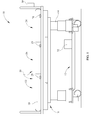
- Fig. 1 is a perspective side view of a person-support apparatus in the vacant mode
- Fig. 2 is a perspective side view of the person-support apparatus along with a person in a person occupied mode
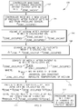
- Fig. 3 is a flow chart of the method used for the determination of pressure relief set points according to an embodiment of the disclosure.
- Fig. 4 is a force diagram showing buoyancy and weight equilibrium according to an embodiment of the disclosure.
- a person-support apparatus 10 according to one illustrative embodiment of the disclosure is shown in Fig. 1 .
- the person-support apparatus 10 in one embodiment would be a hospital bed. In another embodiment, the person-support apparatus 10 could be a stretcher, a wheelchair or any other type of person-support apparatus.
- the person-support apparatus 10 includes a lower frame 12 or base 12, at least one support 14 coupled with the lower frame 12, and an upper frame 16 supported on the supports 14 above the lower frame 12.
- the person-support apparatus 10 supports a person support surface 18 on the upper frame 16.
- the person-support surface 18 is configured to support a person P1 in multiple articulated positions.
- the person-support surface 18 includes at least one zone 20 capable of containing a medium such as air.
- the at least one zone 20 also include foam.
- the at least one zone delivers therapy to the person through expansion/or contraction and changes in pressure of the medium contained in the at least one zone.
- one or more zones of person support surface 18 provide alternating pressure therapy, continuous lateral rotation therapy, low air loss therapy, boost assistance, percussion/vibration therapy, or turn assistance.
- the person support surface includes a head zone 22 configured to support the head of the person P1, a foot zone 24 configured to support the feet of the person P1 and a seat zone 26 configured to support the gluteal region of person P1.
- the person-support apparatus 10 includes a system configured to measure the weight of the person P1 supported on the person-support apparatus 10. The measured weight in turn can be used to calculate pressure relief set points for the at least one zone 20 for the particular person. Pressure relief set points are an optimum pressure which the caregiver needs to maintain within the at least one zone 20. The pressure relief set points can be set inside the at least one zone 20 in such a way that the contact area between the person P1 and the person support surface 18 is optimum.
- the system includes at least one pressure sensor 28 and a controller 30 coupled with the at least one pressure sensor 28 as shown in Figure 1 and Figure 2 .
- the at least one pressure sensor 28 is configured to sense the pressure within the at least one zone 20 and send the sensed value to the controller 30.
- the person-support apparatus 10 further includes a fluid supply unit 32 configured to supply fluid to the at least one zone 20. The operation of the fluid supply unit 32 can be controlled by the controller 30 depending upon the pressure within the at least one zone 20.
- the controller 30 can be any device configured to receive at least one input signal and in one embodiment have the capability to provide at least one output signal. Several types of controllers are well known in the art, including but not limited to programmable or preprogrammed types.
- the system to determine weight of the patient includes at least two modes, with an additional mode to set pressure in the at least one zone in accordance to a pressure relief set point based on the calculated weight of the person obtained from the first two modes.
- this mode is referred to as the vacant mode.
- any pre existing feature such as motion sensors in the person-support apparatus 10, or placed in the room, to detect the presence of the person P1 on the person-support apparatus 10 is well within the scope of this disclosure.
- the person support surface 18 includes a head zone 22, the foot zone 24 and the seat zone 26 which are maintained at predetermined pressures P H1 , P F1 , and P S1 respectively in the vacant mode.
- the vacant mode pressures are maintained high enough such that a person weighing a pre-determined percentile weight of the population will not bottom out the person support surface 18 up on entering the person-support apparatus 10.
- the person support surface 18 comprises one zone.
- the person support surface may include a multitude of zones.
- the person P1 has just entered the person-support apparatus 10 as shown in Figure 2 and this mode is referred to as a person occupied mode. In one embodiment this mode is timed to last ten seconds from the time the person P1 enters the person-support apparatus 10.
- determination that a person is being supported by the person support surface may be made by means of patient switches (not shown) present on the person support surface 18.
- the determination that a person is being supported by the person-support surface 18 may be made from the variation in pressure readings obtained from the at least one pressure sensor 28. The entering of the person P1 on the person-support apparatus 10 will result in the increase of pressure within the at least one zone 20.
- pressure is recorded by the at least one pressure sensor 28 for the head zone 22, the foot zone 24 and the seat zone 26 as P H2 , P F2 , and P S2 respectively in the person occupied mode. Pressure recorded in the person-occupied mode and in the vacant mode is used to determine the weight of the person being supported by the person support surface 18.
- a third optional mode pressure within the at least one zone 20 is adjusted so as to maintain a pressure relief set point in the person support surface 18, accordingly the third optional mode is referred to as pressure relief mode.
- the optimal value of pressure is a discrete value.
- the optimal value of pressure, pressure relief set point may be specified as a range of acceptable pressure values.
- the controller 30 is configured to control the operation of the fluid supply unit 32 to maintain the pressure within the head zone 22, the foot zone 24 and the seat zone 26 at pressure relief set points in one embodiment.
- there may be one or a multitude of zones and the controller 30 is configured to control the operation of the fluid supply unit 32 to maintain the pressures within each zone at pressure relief set points.
- the pressure relief set point is specified as a range of pressure
- the controller 30 is configured to control the operation of the fluid supply unit 32 to maintain the pressure within at least one zone 20 within the specified range of pressure.
- the system is configured to determine the weight of the person P1 supported by the person-support apparatus 10 as shown in flowchart 100 of Figure 3 .
- the pressure within the at least one zone 20 i.e. the head zone 22, the foot zone 24 and the seat zone 26 can be maintained at P H_vacant , P F_vacant , and P S_vacant respectively in the vacant mode.
- pressure within the at least one zone 20 of the person support surface 18 changes.
- the at least one pressure sensor 28 senses the second pressure in the person occupied mode and communicates this value to the controller 30.
- pressures P H_occupied , P F_occupied , and P S_occupied in the head zone 22, the foot zone 24 and the seat zone 26 respectively are recorded.
- pressure P vacant and volume V vacant are known for the at least one zone 20. Therefore the controller 30 can calculate volume V occupied for the at least one zone 20.
- isothermal condition may be assumed and pressure P vacant and volume V vacant are not expected to change from the time the medium was inserted in the at least one zone.
- pressure at the time of insertion of the fluid P initial along with the volume V initial of medium inserted at a particular temperature T initial is recorded.
- T vacant is the temperature of the medium in the vacant mode which may be obtained using a temperature sensor.
- difference in volume is calculated between volume V vacant in the vacant mode and volume V occupied in the person occupied mode in the at least one zone 20.
- the difference in volume is calculated for the head zone 22, the foot zone 24 and the seat zone 26 as ⁇ V H , ⁇ V F and ⁇ V S respectively.
- the controller calculates the weight of the person P1 being supported by individual zones using equation (6) below. Equation (7) alternatively provides the total weight of the person P1 supported by all the zones, found by summing the weight of the person supported by each zone.
- W Person ⁇ ⁇ zone * ⁇ V ZONE
- ⁇ V ZONE can be ⁇ V H , ⁇ V F or ⁇ V S for the head zone 22, the foot zone 24 and the seat zone 26 respectively in one embodiment.
- the controller 30 determines the pressure relief set points for the at least one zone 20 for a particular person P1.
- the pressure relief set points can be changed from person to person depending upon the weight of the person supported on the person-support apparatus 10.
- the pressure relief set point may be defined as a function of the weight of the person.
- the buoyant forces or weight borne by each zone are compared to values from a pre-determined look-up table for optimal pressure relief set point and each zone is set to corresponding pressure relief set points.
- a pressure relief set point is defined as a function of the total weight of the person, or summation of weight borne by all the individual zones determined in the first two modes and all the zones are set to this singular pressure relief set point value.
- medical records obtained from electronic medical records may be used to obtain optimal relationship between patient weight and pressure relief set point or for verifying calculated patient weight.
- EMR electronic medical records
- factors may be taken into account when determining the relationship between weight borne by each zone and the ideal pressure relief set point, including but not limited to body type, whether or not patient is an amputee, medical conditions such as elephantiasis, hydrocephalous or any other medical condition.
Landscapes
- Health & Medical Sciences (AREA)
- Life Sciences & Earth Sciences (AREA)
- Animal Behavior & Ethology (AREA)
- General Health & Medical Sciences (AREA)
- Public Health (AREA)
- Veterinary Medicine (AREA)
- Physics & Mathematics (AREA)
- General Physics & Mathematics (AREA)
- Nursing (AREA)
- Invalid Beds And Related Equipment (AREA)
Abstract
A method and a system have been described to determine a pressure relief set point for a person-support apparatus. The method includes determining the change in pressure or volume in a pressurized zone from a vacant mode to a person occupied mode and computing the weight supported there from.
Description
- A number of commercially available person-support apparatus include an air filled person support surface. Normally, the air within the person support surface can be regulated depending on the patient's requirement. It is preferable that the air pressure inside the person support surface be maintained such that the contact area between the patient and the person support surface is therapeutically optimal to minimize peak interface pressures. Air pressure should also be sufficient so that the weight of patient preferably does not cause the patient to touch the firm, structural bottom of the person support surface. An optimum value of pressure within the person support surface is called as the pressure relief set point. Pressure relief set point values can vary from patient to patient depending, for instance, on their weight as well as potentially other variables. While various systems and methods have been developed to accommodate patients of various weights on a person support surface in an optimal manner, there is still room for improvement. Thus a need persists for further contributions in this area of technology.
- The present disclosure includes one or more of the following features, alone or in any combination.
- One embodiment includes a person-support apparatus comprising:
- a frame;
- a person support surface mounted over at least a portion of said frame, said person support surface comprising at least one pressurized zone;
- at least one pressure sensor configured to sense pressure of a medium in said at least one pressurized zone, said pressure sensor mounted to said person support surface;
- a controller configured to calculate weight of a person supported by at least one pressurized zone of said person support surface based on input received by said at least one pressure sensor.
- Another embodiment of the present disclosure includes a method to determine the weight of a person supported on a person-support apparatus. The method includes the step of maintaining a predetermined pressure in at least one zone of the person support surface in a vacant mode. The next step includes measuring the pressure in at least one zone in a patient occupied mode. The next step includes calculating the volume of the medium in patient occupied mode based on pressure and volume in vacant mode and pressure in patient occupied mode in at least one zone. The next step includes determining the volume difference in a vacant mode and a patient occupied mode in at least one zone of the person support surface. The next step includes determining the air density in at least one zone using the pressure determined in patient occupied mode calculated for at least one zone. A further step includes determining the weight of the person using the density of the medium in the patient occupied mode and the volume difference from the at least one zone. A further step includes determining the pressure relief set point as a function of the weight of the person.
- The invention will now be further described by way of example with reference to the accompanying drawings, in which:
-
Fig. 1 is a perspective side view of a person-support apparatus in the vacant mode; -
Fig. 2 is a perspective side view of the person-support apparatus along with a person in a person occupied mode; -
Fig. 3 is a flow chart of the method used for the determination of pressure relief set points according to an embodiment of the disclosure; and -
Fig. 4 is a force diagram showing buoyancy and weight equilibrium according to an embodiment of the disclosure. - A person-
support apparatus 10 according to one illustrative embodiment of the disclosure is shown inFig. 1 . The person-support apparatus 10 in one embodiment would be a hospital bed. In another embodiment, the person-support apparatus 10 could be a stretcher, a wheelchair or any other type of person-support apparatus. In one embodiment, the person-support apparatus 10 includes alower frame 12 orbase 12, at least onesupport 14 coupled with thelower frame 12, and anupper frame 16 supported on thesupports 14 above thelower frame 12. - The person-
support apparatus 10 supports aperson support surface 18 on theupper frame 16. The person-support surface 18 is configured to support a person P1 in multiple articulated positions. The person-support surface 18 includes at least onezone 20 capable of containing a medium such as air. In one embodiment the at least onezone 20 also include foam. In another embodiment, the at least one zone delivers therapy to the person through expansion/or contraction and changes in pressure of the medium contained in the at least one zone. In one embodiment, one or more zones ofperson support surface 18 provide alternating pressure therapy, continuous lateral rotation therapy, low air loss therapy, boost assistance, percussion/vibration therapy, or turn assistance. According to an illustrative embodiment of the disclosure shown inFigure 1 &Figure 2 , the person support surface includes ahead zone 22 configured to support the head of the person P1, afoot zone 24 configured to support the feet of the person P1 and aseat zone 26 configured to support the gluteal region of person P1. - The person-
support apparatus 10 includes a system configured to measure the weight of the person P1 supported on the person-support apparatus 10. The measured weight in turn can be used to calculate pressure relief set points for the at least onezone 20 for the particular person. Pressure relief set points are an optimum pressure which the caregiver needs to maintain within the at least onezone 20. The pressure relief set points can be set inside the at least onezone 20 in such a way that the contact area between the person P1 and the person supportsurface 18 is optimum. - The system includes at least one
pressure sensor 28 and acontroller 30 coupled with the at least onepressure sensor 28 as shown inFigure 1 andFigure 2 . The at least onepressure sensor 28 is configured to sense the pressure within the at least onezone 20 and send the sensed value to thecontroller 30. The person-support apparatus 10 further includes afluid supply unit 32 configured to supply fluid to the at least onezone 20. The operation of thefluid supply unit 32 can be controlled by thecontroller 30 depending upon the pressure within the at least onezone 20. Thecontroller 30 can be any device configured to receive at least one input signal and in one embodiment have the capability to provide at least one output signal. Several types of controllers are well known in the art, including but not limited to programmable or preprogrammed types. - In one embodiment, the system to determine weight of the patient includes at least two modes, with an additional mode to set pressure in the at least one zone in accordance to a pressure relief set point based on the calculated weight of the person obtained from the first two modes. In the first mode as shown in
Figure 1 , the person P1 is not supported on the person-support apparatus 10 or the person P1 has fully exited from the person-support apparatus 10. Therefore, this mode is referred to as the vacant mode. It should be appreciated that the use of any pre existing feature, such as motion sensors in the person-support apparatus 10, or placed in the room, to detect the presence of the person P1 on the person-support apparatus 10 is well within the scope of this disclosure. In one embodiment theperson support surface 18 includes ahead zone 22, thefoot zone 24 and theseat zone 26 which are maintained at predetermined pressures PH1, PF1, and PS1 respectively in the vacant mode. In one embodiment the vacant mode pressures are maintained high enough such that a person weighing a pre-determined percentile weight of the population will not bottom out theperson support surface 18 up on entering the person-support apparatus 10. In another embodiment, the person supportsurface 18 comprises one zone. In yet another embodiment, the person support surface may include a multitude of zones. - In the second mode, the person P1 has just entered the person-
support apparatus 10 as shown inFigure 2 and this mode is referred to as a person occupied mode. In one embodiment this mode is timed to last ten seconds from the time the person P1 enters the person-support apparatus 10. In one embodiment, determination that a person is being supported by the person support surface may be made by means of patient switches (not shown) present on theperson support surface 18. In another embodiment, the determination that a person is being supported by the person-support surface 18 may be made from the variation in pressure readings obtained from the at least onepressure sensor 28. The entering of the person P1 on the person-support apparatus 10 will result in the increase of pressure within the at least onezone 20. In one embodiment, pressure is recorded by the at least onepressure sensor 28 for thehead zone 22, thefoot zone 24 and theseat zone 26 as PH2, PF2, and PS2 respectively in the person occupied mode. Pressure recorded in the person-occupied mode and in the vacant mode is used to determine the weight of the person being supported by theperson support surface 18. - In a third optional mode, pressure within the at least one
zone 20 is adjusted so as to maintain a pressure relief set point in theperson support surface 18, accordingly the third optional mode is referred to as pressure relief mode. In one embodiment, the optimal value of pressure is a discrete value. In another embodiment, the optimal value of pressure, pressure relief set point, may be specified as a range of acceptable pressure values. In the third mode, thecontroller 30 is configured to control the operation of thefluid supply unit 32 to maintain the pressure within thehead zone 22, thefoot zone 24 and theseat zone 26 at pressure relief set points in one embodiment. In another embodiment, there may be one or a multitude of zones, and thecontroller 30 is configured to control the operation of thefluid supply unit 32 to maintain the pressures within each zone at pressure relief set points. In yet another embodiment, the pressure relief set point is specified as a range of pressure, and thecontroller 30 is configured to control the operation of thefluid supply unit 32 to maintain the pressure within at least onezone 20 within the specified range of pressure. - In operation, the system is configured to determine the weight of the person P1 supported by the person-
support apparatus 10 as shown inflowchart 100 ofFigure 3 . Atstep 102 the pressure within the at least onezone 20 i.e. thehead zone 22, thefoot zone 24 and theseat zone 26 can be maintained at PH_vacant, PF_vacant, and PS_vacant respectively in the vacant mode. Upon a person P1 entering the person-support apparatus 10, pressure within the at least onezone 20 of theperson support surface 18 changes. Atstep 104, the at least onepressure sensor 28 senses the second pressure in the person occupied mode and communicates this value to thecontroller 30. In one embodiment, pressures PH_occupied, PF_occupied, and PS_occupied in thehead zone 22, thefoot zone 24 and theseat zone 26 respectively are recorded. Thecontroller 30 may in one embodiment determine the difference between the first pressure and the second pressure i.e. ΔPH, ΔPF and ΔPS as follows:


- In
step 106, thecontroller 30 determines the volume of the medium, in the at least onezone 20 in the person occupied mode as follows:
Where, Pvacant is the pressure in the at least onezone 20 in vacant mode;
Vvacant is the volume of medium in the at least onezone 20 which is found from the amount of fluid initially inserted in the at least onezone 20;
Poccupied is the pressure in at least one zone in the person occupied mode; and
Voccupied is the volume of the at least one zone in the person occupied mode. - In equation (4) pressure Pvacant and volume Vvacant are known for the at least one
zone 20. Therefore thecontroller 30 can calculate volume Voccupied for the at least onezone 20. In equation (4), isothermal condition may be assumed and pressure Pvacant and volume Vvacant are not expected to change from the time the medium was inserted in the at least one zone. In another embodiment, pressure at the time of insertion of the fluid Pinitial, along with the volume Vinitial of medium inserted at a particular temperature Tinitial is recorded. Volume Vvacant in the vacant mode can be found as:
Where, Tvacant is the temperature of the medium in the vacant mode which may be obtained using a temperature sensor. - At
step 108, difference in volume is calculated between volume Vvacant in the vacant mode and volume Voccupied in the person occupied mode in the at least onezone 20. In one embodiment, the difference in volume is calculated for thehead zone 22, thefoot zone 24 and theseat zone 26 as ΔVH, ΔVF and ΔVS respectively. - At
step 110, thecontroller 30 calculates an air density ρzone inside the at least onezone 20 for the person occupied mode using following equation:
Where: Mmed is the molar mass of the medium in the at least one zone;
R is the universal gas constant; and
Toccupied is the ambient absolute temperature in the person occupied mode; since the time lag between vacant and patient occupied mode measurements is expected to be relatively small, temperature in the vacant mode can be used alternatively in equation (5) instead of that in the occupied mode. The difference in the two temperatures (vacant mode and patient occupied mode) is expected to be miniscule and is neglected in this embodiment. - At
step 112, the controller calculates the weight of the person P1 being supported by individual zones using equation (6) below. Equation (7) alternatively provides the total weight of the person P1 supported by all the zones, found by summing the weight of the person supported by each zone.

Where, ΔVZONE can be ΔVH, ΔVF or ΔVS for thehead zone 22, thefoot zone 24 and theseat zone 26 respectively in one embodiment. - As the person P1 settles on the
person support surface 18, the buoyant forces BZONE between the air in theperson support surface 18 and the person's weight WZONE balance to attain equilibrium as shown inFigure 4 . - In an
optional step 114 thecontroller 30 determines the pressure relief set points for the at least onezone 20 for a particular person P1. The pressure relief set points can be changed from person to person depending upon the weight of the person supported on the person-support apparatus 10. The pressure relief set point may be defined as a function of the weight of the person. In one embodiment, the buoyant forces or weight borne by each zone are compared to values from a pre-determined look-up table for optimal pressure relief set point and each zone is set to corresponding pressure relief set points. In yet another embodiment, a pressure relief set point is defined as a function of the total weight of the person, or summation of weight borne by all the individual zones determined in the first two modes and all the zones are set to this singular pressure relief set point value. In another embodiment medical records obtained from electronic medical records (EMR) may be used to obtain optimal relationship between patient weight and pressure relief set point or for verifying calculated patient weight. Several factors may be taken into account when determining the relationship between weight borne by each zone and the ideal pressure relief set point, including but not limited to body type, whether or not patient is an amputee, medical conditions such as elephantiasis, hydrocephalous or any other medical condition. - Any theory, mechanism of operation, proof, or finding stated herein is meant to further enhance understanding of principles of the present disclosure and is not intended to make the present disclosure in any way dependent upon such theory, mechanism of operation, illustrative embodiment, proof, or finding. It should be understood that while the use of the word preferable, preferably or preferred in the description above indicates that the feature so described can be more desirable, it nonetheless can not be necessary and embodiments lacking the same are contemplated.
- While embodiments of the disclosure have been illustrated and described in detail in the drawings and foregoing description, the same are to be considered as illustrative and not intended to be exhaustive or to limit the disclosure to the precise forms disclosed. Additional alternatives, modifications and variations can be apparent to those skilled in the art. Also, while multiple inventive aspects and principles can have been presented, they need not be utilized in combination, and various combinations of inventive aspects and principles are possible in light of the various embodiments provided above.
- Embodiments of the invention can be described with reference to the following numbered clauses, with preferred features laid out in the dependent clauses:
- 1. A method of determining the weight of patient supported by a person support surface comprising:
- maintaining a predetermined pressure in at least one zone in said person support surface while said patient is not supported by said person support surface in a first mode;
- recording a second value of pressure in said at least one zone in said person support surface after said patient exerts weight on and is supported by said person support surface in a second mode;
- determining volume of a medium in said at least one zone of said person support surface in said second mode using said predetermined pressure in first mode, said second value of pressure in second mode and volume of the medium in first mode;
- determining a volume difference between said volume of medium in first mode and said volume of medium in second mode;
- determining density of medium in second mode using at least said second value of pressure;
- approximating weight of the person using said density of medium in said second mode and said volume difference.
- 2. The method of clause 1, said person support surface including at least one pressure sensor in said at least one zone to measure said second value of pressure.
- 3. The method of clause 2, said second value of pressure, said volume difference and said density of medium are calculated for at least two zones.
- 4. The method of
clause 3, further comprising the step of determining individual pressure relief set points for each said zone by comparing approximated weight borne by each said zone with a pre-determined relationship with optimal pressure relief set point values. - 5. The method of
clause 3, said weight of the person is determined by summing components of weight of the person supported by each of said at least two zones, said components of weight of the person for each of said at least two zones are calculated based on said density of medium in said second mode and said volume difference in each of said at least two zones between said first mode and said second mode. - 6. The method of clause 5, further comprising the step of determining a pressure relief point based on comparing the summed components of the person's weight supported by said zones with a pre-determined relationship with optimal pressure relief set point values.
- 7. A person-support apparatus comprising:
- a frame;
- a person support surface mounted over at least a portion of said frame, said person support surface comprising at least one pressurized zone;
- at least one pressure sensor configured to sense pressure of a medium in said at least one pressurized zone, said pressure sensor mounted to said person support surface;
- a controller configured to calculate weight of a person supported by at least one pressurized zone of said person support surface based on input received by said at least one pressure sensor.
- 8. The person-support apparatus of clause 7, further comprising a fluid supply unit, said controller configured to control said fluid supply unit to vary pressure of said medium in said at least one zone.
- 9. The person-support apparatus of clause 8, said controller configured to determine at least one pressure relief set point based on said calculated weight of person.
- 10. The person-support apparatus of clause 9, said controller configured to determine said at least one pressure relief set point based on at least one value in a look-up table correlating said at least one pressure relief set point and said calculated weight of person.
- 11. The person-support apparatus of clause 9, said controller configured to control said fluid supply unit to maintain pressure in said at least one pressurized zone at said pressure relief set point.
- 12. The person-support apparatus of clause 7, said controller configured to determine volume of medium in said at least one pressurized zone of said person support surface in an occupied mode using a predetermined pressure in a vacant mode, a value of pressure in said occupied mode and a volume of medium in said vacant mode.
- 13. The person-support apparatus of
clause 12, said controller configured to determine a volume difference between said volume of medium in said vacant mode and said volume of medium in said at least one pressurized zone of said person support surface in said occupied mode. - 14. The person-support apparatus of clause 13, said controller configured to determine density of medium in said occupied mode using at least said value of pressure in said occupied mode.
- 15. The person-support apparatus of
clause 14, said controller configured to approximate weight of a person supported by said person support surface using said density of medium in said occupied mode and said volume difference. - 16. The person-support apparatus of clause 15, said controller configured to control said fluid supply unit to maintain pressure in said at least one pressurized zone at a pressure relief set point.
- 17. A person-support apparatus with a frame, a person support surface mounted over at least a portion of the frame comprising:
- at least one pressure sensor configured to sense pressure in at least one pressurized zone of said person support surface;
- a controller configured to calculate the weight of a person supported by at least one pressurized zone of said person support surface based on input received by said at least one pressure sensor.
- 18. The person-support apparatus of clause 17, further comprising a fluid supply unit, said controller configured to control said fluid supply unit to vary pressure of said medium in said at least one zone.
- 19. The person-support apparatus of
clause 18, said controller configured to determine at least one pressure relief set point based on said calculated weight of person. - 20. The person-support apparatus of clause 19, said controller configured to control said fluid supply unit to maintain pressure in said at least one zone at said pressure relief set point.
Claims (10)
- A person-support apparatus comprising
a frame,
a person support surface mounted over at least a portion of said frame, said person support surface comprising at least one pressurized zone,
at least one pressure sensor configured to sense pressure of a medium in said at least one pressurized zone, said pressure sensor mounted to said person support surface, and
a controller configured to calculate weight of a person supported by at least one pressurized zone of said person support surface based on input received by said at least one pressure sensor. - The person-support apparatus of claim 1, further comprising a fluid supply unit, said controller configured to control said fluid supply unit to vary pressure of said medium in said at least one zone.
- The person-support apparatus of claim 2, said controller configured to determine at least one pressure relief set point based on said calculated weight of person.
- The person-support apparatus of claim 3, said controller configured to determine said at least one pressure relief set point based on at least one value in a look-up table correlating said at least one pressure relief set point and said calculated weight of person.
- The person-support apparatus of either claim 3 or claim 4, said controller configured to control said fluid supply unit to maintain pressure in said at least one pressurized zone at said pressure relief set point.
- The person-support apparatus of any preceding claim, said controller configured to determine volume of medium in said at least one pressurized zone of said person support surface in an occupied mode using a predetermined pressure in a vacant mode, a value of pressure in said occupied mode and a volume of medium in said vacant mode.
- The person-support apparatus of claim 6, said controller configured to determine a volume difference between said volume of medium in said vacant mode and said volume of medium in said at least one pressurized zone of said person support surface in said occupied mode.
- The person-support apparatus of claim 7, said controller configured to determine density of medium in said occupied mode using at least said value of pressure in said occupied mode.
- The person-support apparatus of claim 8, said controller configured to approximate weight of a person supported by said person support surface using said density of medium in said occupied mode and said volume difference.
- The person-support apparatus of claim 9, said controller configured to control said fluid supply unit to maintain pressure in said at least one pressurized zone at a pressure relief set point.
Applications Claiming Priority (1)
| Application Number | Priority Date | Filing Date | Title |
|---|---|---|---|
| US13/242,048 US9009891B2 (en) | 2011-09-23 | 2011-09-23 | Automatic patient weight measurement for determining pressure relief set points |
Publications (1)
| Publication Number | Publication Date |
|---|---|
| EP2573527A1 true EP2573527A1 (en) | 2013-03-27 |
Family
ID=47022485
Family Applications (1)
| Application Number | Title | Priority Date | Filing Date |
|---|---|---|---|
| EP12185378A Withdrawn EP2573527A1 (en) | 2011-09-23 | 2012-09-21 | Automatic patient weight measurement for determining pressure relief set points |
Country Status (3)
| Country | Link |
|---|---|
| US (1) | US9009891B2 (en) |
| EP (1) | EP2573527A1 (en) |
| AU (1) | AU2012227273A1 (en) |
Families Citing this family (27)
| Publication number | Priority date | Publication date | Assignee | Title |
|---|---|---|---|---|
| US20140000030A1 (en) * | 2012-06-18 | 2014-01-02 | Hill-Rom Services, Inc. | Lift system for a person support apparatus |
| US11243110B2 (en) * | 2014-05-09 | 2022-02-08 | Daniel Lin | Method and system to track weight without stepping on a weight scale |
| US10466094B2 (en) * | 2014-05-09 | 2019-11-05 | Daniel Lin | Method and system to track weight without stepping on a weight scale |
| WO2016112023A1 (en) | 2015-01-05 | 2016-07-14 | Select Comfort Corporation | Bed with user occupancy tracking |
| CN105708628A (en) * | 2016-01-14 | 2016-06-29 | 浙江海洋学院 | Multifunctional stretcher for boats |
| US11173085B2 (en) | 2017-12-28 | 2021-11-16 | Stryker Corporation | Mattress cover for a mattress providing rotation therapy to a patient |
| US11246775B2 (en) | 2017-12-28 | 2022-02-15 | Stryker Corporation | Patient turning device for a patient support apparatus |
| USD888964S1 (en) | 2018-09-28 | 2020-06-30 | Stryker Corporation | Crib assembly for a patient support |
| USD977109S1 (en) | 2018-09-28 | 2023-01-31 | Stryker Corporation | Crib assembly for a patient support |
| USD888963S1 (en) | 2018-09-28 | 2020-06-30 | Stryker Corporation | Cover assembly for a patient support |
| USD879966S1 (en) | 2018-09-28 | 2020-03-31 | Stryker Corporation | Crib assembly |
| USD877915S1 (en) | 2018-09-28 | 2020-03-10 | Stryker Corporation | Crib assembly |
| USD888962S1 (en) | 2018-09-28 | 2020-06-30 | Stryker Corporation | Cover assembly for a patient support |
| USD894956S1 (en) | 2018-10-31 | 2020-09-01 | Stryker Corporation | Display screen or portion thereof with graphical user interface |
| USD894223S1 (en) | 2018-10-31 | 2020-08-25 | Stryker Corporation | Display screen with animated graphical user interface |
| USD894957S1 (en) | 2018-10-31 | 2020-09-01 | Stryker Corporation | Display screen or portion thereof with graphical user interface |
| USD894226S1 (en) | 2018-10-31 | 2020-08-25 | Stryker Corporation | Display screen or portion thereof with graphical user interface |
| USD893543S1 (en) | 2018-10-31 | 2020-08-18 | Stryker Corporation | Display screen with graphical user interface |
| USD890914S1 (en) | 2018-10-31 | 2020-07-21 | Stryker Corporation | Pump |
| USD892159S1 (en) | 2018-10-31 | 2020-08-04 | Stryker Corporation | Display screen with animated graphical user interface |
| CN109199768A (en) * | 2018-11-05 | 2019-01-15 | 张树忠 | A kind of movably connected Neurology clinical diagnosis device |
| US11931312B2 (en) * | 2019-03-29 | 2024-03-19 | Hill-Rom Services, Inc. | User interface for a patient support apparatus with integrated patient therapy device |
| CN109998795B (en) * | 2019-04-25 | 2023-11-21 | 西安交通大学医学院第一附属医院 | Pressure injury prevention mattress used on flat car |
| CN110200763A (en) * | 2019-04-26 | 2019-09-06 | 浙江大学 | A kind of medical suspension bed weighing system and method |
| CN111924189B (en) * | 2020-07-30 | 2022-04-01 | 胡中大 | Assembly line weighing and packaging table with chain type plate scale |
| US12510400B1 (en) * | 2021-06-18 | 2025-12-30 | Hinckley Medical, Inc. | Patient weighing system for a patient transport device |
| US12117334B1 (en) | 2021-06-18 | 2024-10-15 | Hinkley Medical, Inc. | Patient weighing system for a patient transport device |
Citations (3)
| Publication number | Priority date | Publication date | Assignee | Title |
|---|---|---|---|---|
| US5957491A (en) * | 1996-12-19 | 1999-09-28 | Automotive Systems Laboratory, Inc. | Seat weight sensor having fluid filled bladder |
| US20070272450A1 (en) * | 2003-12-12 | 2007-11-29 | Hill-Rom Services, Inc. | Seat Force Sensor |
| GB2453371A (en) * | 2007-10-05 | 2009-04-08 | Harvest Healthcare | A method of weighing a patient using a fluid-fillable mattress |
Family Cites Families (6)
| Publication number | Priority date | Publication date | Assignee | Title |
|---|---|---|---|---|
| EP0408636A4 (en) | 1988-03-23 | 1992-01-02 | Robert Ferrand | Patient support system |
| US6065166A (en) * | 1996-10-17 | 2000-05-23 | O.R. Comfort, Llc | Surgical support cushion apparatus and method |
| US5963997A (en) | 1997-03-24 | 1999-10-12 | Hagopian; Mark | Low air loss patient support system providing active feedback pressure sensing and correction capabilities for use as a bed mattress and a wheelchair seating system |
| FR2774573B1 (en) | 1998-02-09 | 2000-04-28 | Support Systems International | METHOD AND APPARATUS FOR SUPPORTING A SUPPORTING ELEMENT, IN PARTICULAR THE BODY OF A PATIENT, WITH AN INTEGRATED DYNAMIC AND AUTOMATIC PRESSURE BALANCE SYSTEM |
| ATE482635T1 (en) * | 2002-03-18 | 2010-10-15 | Hill Rom Services Inc | HOSPITAL BED WITH A REGULATED INFLATABLE PAD |
| US8832883B2 (en) * | 2010-06-12 | 2014-09-16 | American Home Health Care, Inc. | Patient support systems |
-
2011
- 2011-09-23 US US13/242,048 patent/US9009891B2/en active Active
-
2012
- 2012-09-21 EP EP12185378A patent/EP2573527A1/en not_active Withdrawn
- 2012-09-21 AU AU2012227273A patent/AU2012227273A1/en not_active Abandoned
Patent Citations (3)
| Publication number | Priority date | Publication date | Assignee | Title |
|---|---|---|---|---|
| US5957491A (en) * | 1996-12-19 | 1999-09-28 | Automotive Systems Laboratory, Inc. | Seat weight sensor having fluid filled bladder |
| US20070272450A1 (en) * | 2003-12-12 | 2007-11-29 | Hill-Rom Services, Inc. | Seat Force Sensor |
| GB2453371A (en) * | 2007-10-05 | 2009-04-08 | Harvest Healthcare | A method of weighing a patient using a fluid-fillable mattress |
Also Published As
| Publication number | Publication date |
|---|---|
| US20130074262A1 (en) | 2013-03-28 |
| AU2012227273A1 (en) | 2013-04-11 |
| US9009891B2 (en) | 2015-04-21 |
Similar Documents
| Publication | Publication Date | Title |
|---|---|---|
| US9009891B2 (en) | Automatic patient weight measurement for determining pressure relief set points | |
| EP1700088B1 (en) | Seat force sensor | |
| EP1572059B1 (en) | Hospital bed with controlled inflatable portion of patient support | |
| US8087113B2 (en) | Inflatable support | |
| EP2995242B1 (en) | Patient support apparatus | |
| IE64768B1 (en) | Inflation control for air supports | |
| US20090076756A1 (en) | Weight measuring apparatus | |
| KR20180079957A (en) | Sleep management mattress | |
| EP2893847B1 (en) | Smart adjustable bed and method for adjusting of stiffness of a bed in real time | |
| EP2068133A1 (en) | Apparatus and method for measuring the body weight | |
| DK1482891T3 (en) | Inflatable support | |
| US7842892B2 (en) | Apparatus and method for measuring the body weight | |
| JP2019148579A (en) | Cushion comprising weighing machine | |
| EP0482267B1 (en) | Method for weighing human body and the like | |
| WO2004073577A1 (en) | Pad | |
| EP2735293A1 (en) | Apparatus with inflatable mattress and method for supporting a patient with said apparatus | |
| EP4702956A1 (en) | Pressure controlled mattress for an infant care device | |
| CN121419712A (en) | System for measuring hemodynamic parameters |
Legal Events
| Date | Code | Title | Description |
|---|---|---|---|
| PUAI | Public reference made under article 153(3) epc to a published international application that has entered the european phase |
Free format text: ORIGINAL CODE: 0009012 |
|
| AK | Designated contracting states |
Kind code of ref document: A1 Designated state(s): AL AT BE BG CH CY CZ DE DK EE ES FI FR GB GR HR HU IE IS IT LI LT LU LV MC MK MT NL NO PL PT RO RS SE SI SK SM TR |
|
| AX | Request for extension of the european patent |
Extension state: BA ME |
|
| STAA | Information on the status of an ep patent application or granted ep patent |
Free format text: STATUS: THE APPLICATION IS DEEMED TO BE WITHDRAWN |
|
| 18D | Application deemed to be withdrawn |
Effective date: 20130928 |