EP2573326A1 - Airfoil tip air seal assembly - Google Patents
Airfoil tip air seal assembly Download PDFInfo
- Publication number
- EP2573326A1 EP2573326A1 EP12182687A EP12182687A EP2573326A1 EP 2573326 A1 EP2573326 A1 EP 2573326A1 EP 12182687 A EP12182687 A EP 12182687A EP 12182687 A EP12182687 A EP 12182687A EP 2573326 A1 EP2573326 A1 EP 2573326A1
- Authority
- EP
- European Patent Office
- Prior art keywords
- assembly
- airfoil
- rotor
- blade
- tip
- Prior art date
- Legal status (The legal status is an assumption and is not a legal conclusion. Google has not performed a legal analysis and makes no representation as to the accuracy of the status listed.)
- Withdrawn
Links
- 238000000576 coating method Methods 0.000 claims abstract description 99
- 239000011248 coating agent Substances 0.000 claims abstract description 85
- 229910001069 Ti alloy Inorganic materials 0.000 claims description 5
- 238000000342 Monte Carlo simulation Methods 0.000 claims description 4
- 239000000919 ceramic Substances 0.000 claims description 3
- 239000011159 matrix material Substances 0.000 claims description 3
- 229910052582 BN Inorganic materials 0.000 claims description 2
- PZNSFCLAULLKQX-UHFFFAOYSA-N Boron nitride Chemical compound N#B PZNSFCLAULLKQX-UHFFFAOYSA-N 0.000 claims description 2
- 239000000463 material Substances 0.000 description 11
- 239000007789 gas Substances 0.000 description 8
- 230000000712 assembly Effects 0.000 description 6
- 238000000429 assembly Methods 0.000 description 6
- 230000000694 effects Effects 0.000 description 6
- 238000012545 processing Methods 0.000 description 5
- 239000012720 thermal barrier coating Substances 0.000 description 5
- 238000005452 bending Methods 0.000 description 4
- 238000009826 distribution Methods 0.000 description 4
- 229910052751 metal Inorganic materials 0.000 description 4
- 239000002184 metal Substances 0.000 description 4
- 238000004088 simulation Methods 0.000 description 4
- 239000003082 abrasive agent Substances 0.000 description 3
- PXHVJJICTQNCMI-UHFFFAOYSA-N nickel Substances [Ni] PXHVJJICTQNCMI-UHFFFAOYSA-N 0.000 description 3
- 238000007789 sealing Methods 0.000 description 3
- 238000012360 testing method Methods 0.000 description 3
- RTAQQCXQSZGOHL-UHFFFAOYSA-N Titanium Chemical compound [Ti] RTAQQCXQSZGOHL-UHFFFAOYSA-N 0.000 description 2
- 238000013459 approach Methods 0.000 description 2
- 230000015572 biosynthetic process Effects 0.000 description 2
- 238000002485 combustion reaction Methods 0.000 description 2
- 230000005484 gravity Effects 0.000 description 2
- 229910052759 nickel Inorganic materials 0.000 description 2
- 239000002245 particle Substances 0.000 description 2
- 239000007921 spray Substances 0.000 description 2
- 239000010936 titanium Substances 0.000 description 2
- 238000011144 upstream manufacturing Methods 0.000 description 2
- 229910001233 yttria-stabilized zirconia Inorganic materials 0.000 description 2
- 229910000990 Ni alloy Inorganic materials 0.000 description 1
- 229910000883 Ti6Al4V Inorganic materials 0.000 description 1
- 230000002159 abnormal effect Effects 0.000 description 1
- 230000001133 acceleration Effects 0.000 description 1
- 230000002411 adverse Effects 0.000 description 1
- 229910045601 alloy Inorganic materials 0.000 description 1
- 239000000956 alloy Substances 0.000 description 1
- 230000008901 benefit Effects 0.000 description 1
- 238000005229 chemical vapour deposition Methods 0.000 description 1
- 230000002301 combined effect Effects 0.000 description 1
- 150000001875 compounds Chemical class 0.000 description 1
- 230000006835 compression Effects 0.000 description 1
- 238000007906 compression Methods 0.000 description 1
- 238000007796 conventional method Methods 0.000 description 1
- 238000001816 cooling Methods 0.000 description 1
- 238000013461 design Methods 0.000 description 1
- 238000009713 electroplating Methods 0.000 description 1
- 239000012530 fluid Substances 0.000 description 1
- 239000000446 fuel Substances 0.000 description 1
- 238000003754 machining Methods 0.000 description 1
- 230000014759 maintenance of location Effects 0.000 description 1
- 238000000034 method Methods 0.000 description 1
- 238000012986 modification Methods 0.000 description 1
- 230000004048 modification Effects 0.000 description 1
- 238000005240 physical vapour deposition Methods 0.000 description 1
- 239000011253 protective coating Substances 0.000 description 1
- 230000008439 repair process Effects 0.000 description 1
- 125000006850 spacer group Chemical group 0.000 description 1
- 239000000758 substrate Substances 0.000 description 1
- 229910000601 superalloy Inorganic materials 0.000 description 1
- 229910052719 titanium Inorganic materials 0.000 description 1
- RUDFQVOCFDJEEF-UHFFFAOYSA-N yttrium(III) oxide Inorganic materials [O-2].[O-2].[O-2].[Y+3].[Y+3] RUDFQVOCFDJEEF-UHFFFAOYSA-N 0.000 description 1
Images



Classifications
-
- F—MECHANICAL ENGINEERING; LIGHTING; HEATING; WEAPONS; BLASTING
- F01—MACHINES OR ENGINES IN GENERAL; ENGINE PLANTS IN GENERAL; STEAM ENGINES
- F01D—NON-POSITIVE DISPLACEMENT MACHINES OR ENGINES, e.g. STEAM TURBINES
- F01D5/00—Blades; Blade-carrying members; Heating, heat-insulating, cooling or antivibration means on the blades or the members
- F01D5/12—Blades
- F01D5/14—Form or construction
- F01D5/20—Specially-shaped blade tips to seal space between tips and stator
-
- F—MECHANICAL ENGINEERING; LIGHTING; HEATING; WEAPONS; BLASTING
- F01—MACHINES OR ENGINES IN GENERAL; ENGINE PLANTS IN GENERAL; STEAM ENGINES
- F01D—NON-POSITIVE DISPLACEMENT MACHINES OR ENGINES, e.g. STEAM TURBINES
- F01D11/00—Preventing or minimising internal leakage of working-fluid, e.g. between stages
- F01D11/08—Preventing or minimising internal leakage of working-fluid, e.g. between stages for sealing space between rotor blade tips and stator
- F01D11/12—Preventing or minimising internal leakage of working-fluid, e.g. between stages for sealing space between rotor blade tips and stator using a rubstrip, e.g. erodible. deformable or resiliently-biased part
-
- F—MECHANICAL ENGINEERING; LIGHTING; HEATING; WEAPONS; BLASTING
- F01—MACHINES OR ENGINES IN GENERAL; ENGINE PLANTS IN GENERAL; STEAM ENGINES
- F01D—NON-POSITIVE DISPLACEMENT MACHINES OR ENGINES, e.g. STEAM TURBINES
- F01D11/00—Preventing or minimising internal leakage of working-fluid, e.g. between stages
- F01D11/08—Preventing or minimising internal leakage of working-fluid, e.g. between stages for sealing space between rotor blade tips and stator
- F01D11/12—Preventing or minimising internal leakage of working-fluid, e.g. between stages for sealing space between rotor blade tips and stator using a rubstrip, e.g. erodible. deformable or resiliently-biased part
- F01D11/122—Preventing or minimising internal leakage of working-fluid, e.g. between stages for sealing space between rotor blade tips and stator using a rubstrip, e.g. erodible. deformable or resiliently-biased part with erodable or abradable material
-
- F—MECHANICAL ENGINEERING; LIGHTING; HEATING; WEAPONS; BLASTING
- F05—INDEXING SCHEMES RELATING TO ENGINES OR PUMPS IN VARIOUS SUBCLASSES OF CLASSES F01-F04
- F05D—INDEXING SCHEME FOR ASPECTS RELATING TO NON-POSITIVE-DISPLACEMENT MACHINES OR ENGINES, GAS-TURBINES OR JET-PROPULSION PLANTS
- F05D2260/00—Function
- F05D2260/96—Preventing, counteracting or reducing vibration or noise
- F05D2260/961—Preventing, counteracting or reducing vibration or noise by mistuning rotor blades or stator vanes with irregular interblade spacing, airfoil shape
Definitions
- the invention relates generally to air seal assemblies for a gas turbine engine, and more specifically to rotor assemblies for air seal assemblies.
- each operative section of a gas turbine engine includes a variety of seals and coatings. Maintaining appropriate clearances between moving parts and adjacent stationary parts is critical to balancing efficiency and improving stability to limit damage to the engine. Too small of a clearance results in increased contact severity and frequency between components, particularly due to maneuver loads, rapid temperature changes, and other sudden changes in engine operation. Excessive clearance can cause efficiency losses from lost work embodied in the compressed gases escaping through gaps between respective rotor and stator elements. Large clearances also increase the risk and severity of operational instability such as compressor surge.
- every blade tip on a rotor is abrasively coated to run a groove into an abradable coating on the casing to form a seal.
- stator vanes include an abradable seal coating on all of the vane tips or shrouds that are rubbed by an abrasive coating on the rotor land.
- coating every blade tip or every vane is quite expensive and time-consuming. The coating process itself is subject to error which can also result in additional repair or scrapping of the entire component or assembly.
- An air seal assembly for a gas turbine engine the air seal comprises a first assembly and a second assembly.
- One of the first assembly and the second assembly is rotatable relative to the other of the first assembly and the second assembly.
- the second assembly is aligned annularly with the first assembly and includes a circumferential surface with an abradable coating disposed annularly adjacent to the first and second airfoil tips.
- the first assembly includes at least one first airfoil with a first tip having an abrasive coating, and at least one second airfoil with a second tip absent the abrasive coating, the at least one first airfoil co-aligned axially and intermingled with a respective at least one second airfoil around a periphery of the first assembly.
- a rotor assembly comprises a rotor disc, at least one first rotor blade and at least one second rotor blade.
- the at least one first rotor blade includes a first airfoil tip with an abrasive coating.
- the at least one second rotor blade includes a second airfoil tip absent an abrasive coating.
- the at least one first rotor blade is intermingled and co-aligned with a respective at least one second rotor blade axially around a periphery of the rotor disc.
- FIG. 1A schematically depicts a cross-section of a gas turbine engine.
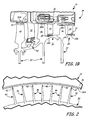
- FIG. 1B shows a cross-section of a portion of the high pressure compressor (HPC) section of the engine.
- HPC high pressure compressor
- FIG. 2 is a magnified portion of a blade outer air seal (BOAS) in the HPC prior to engine run-in.
- BOAS blade outer air seal
- FIG. 3A is magnified view of one portion of the BOAS prior to run-in.
- FIG. 3B shows the magnified portion of the BOAS from FIG. 3A after run-in.
- FIG. 3C is a magnified first blade tip with an abrasive coating.
- FIG. 3D is a magnified uncoated second blade tip absent an abrasive coating.
- FIG. 4 shows a first blade prior to being coated adjacent a second uncoated blade.
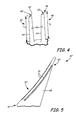
- FIG. 5 is a magnified view of a processed first blade with squealer tip cuts.
- FIG. 6 is a magnified view of a portion of an inner air seal.
- FIG. 7 depicts an alternative embodiment of the integrally bladed rotor (IBR) with individual first and second blades secured to a traditional rotor disc.
- IBR integrally bladed rotor
- FIG. 1A shows engine 10, fan section 12, low-pressure compressor section 14, high-pressure compressor section 16, combustor section 18, high-pressure turbine section 20, low-pressure turbine section 22, bypass 24, low-pressure shaft 26, and high-pressure shaft 28.
- FIG. 1A schematically depicts an axial cross-section of an example dual-spool turbofan engine 10.
- a portion of atmospheric air pulled in by rotation of fan section 12 is directed toward low-pressure compressor section 14, while the remainder is directed through bypass section 24.
- Air entering low-pressure compressor section 14 is further compressed by high-pressure compressor section 16.
- Fuel is added to the compressed air and ignited in combustor section 18.
- Blades in turbine sections 20 and 22 capture a portion of the energy from expanding combustion products.
- Both fan section 12 and low-pressure compressor section 14 are rotatably linked via low-pressure shaft 26 to low-pressure power turbine section 22.
- High-pressure compressor section 16 is rotatably connected to high-pressure turbine section 22 via high-pressure shaft 28. Thrust is generated in engine 10 by the force of the air drawn in by fan section 12 and pushed through bypass section 24, and by the force of exhaust gases exiting from low-pressure turbine section 22.
- Engine 10 is shown as a dual-spool turbofan engine. However, this is merely one application of the inventive concepts described herein.
- the blade, vane, and seal arrangements described below can be readily adapted to other compressor sections as well as to fan section 12, low-pressure compressor 14, and turbine sections 20, 22.
- the concepts can also be adapted to other turbofan engines with a single spool or with multiple spools, as well as to other types of gas turbine engines including industrial gas turbines (IGTs), turboprops, and turboshafts.
- IGTs industrial gas turbines
- turboprops turboprops
- turboshafts turboshafts
- FIG. 1B includes low-pressure compressor section 16, IBR assemblies 30, shrouded stator vane 31, first cantilevered stator vane 32, second cantilevered stator vane 33, casing 34, first coated stator vane tip 35, seal ring 36, second uncoated stator vane tip 37, outer and inner abradable seal coatings 38A, 38B, rotor lands 39, first blades 40, coated first blade tips 42, second rotor blades 46, uncoated second blade tips 48, and knife edge seals 50.
- FIG. 1B is an axial cross-section of a portion of compressor section 16, which includes multiple compressor stages where each stage has a rotor assembly 30 and a respective stator assembly.
- rotor assembly 30 includes blades extending radially outward adjacent to an adjacent circumferential surface such as seal ring 36 secured to casing 34.
- Rotor assembly 30 cooperates with a stator disposed axially downstream to progressively compress and direct inlet air axially into subsequent stages toward combustor 18 (shown in FIG. 1A ).
- Stator vanes are mounted circumferentially and extend radially inward from compressor casing 34 toward an adjacent circumferential surface such as rotor lands 39.
- compressor section 16 includes shrouded stator vanes 31 at the initial upstream stages, and cantilevered vanes 32, 33 in the higher downstream stages.
- rotor assemblies 30 are integrally bladed rotors (IBR's), which are also known in the art as blisks.
- IBR assemblies 30 include both first blades 40 and second blades 46 integrally secured thereto.
- Each IBR 30 has at least one first blade 40 with abrasively coated airfoil tip 42 and at least one second blade 46 with uncoated airfoil tip 48.
- Coated first airfoil tips 42 interact with seal rings 36 to form a groove for a blade outer air seal (BOAS) in outer abradable coating 38A.
- BOAS blade outer air seal
- shrouded vanes 31 are mounted conventionally to casing 34.
- Shrouded vanes 31 include conventional labyrinth seal 50 to minimize airflow therepast.
- labyrinth seals 50 are disposed in lower compressor stages while the upper compressor stages can include the inner air seal as described below. The particular number and distribution of inner air seals and labyrinth seals can be determined via simulation.
- cantilevered vanes 32, 33 can be adapted to interact with inner abradable coatings 38B on adjacent rotor lands 39 to form an inner air seal.
- Casing 34 includes one seal ring 36 at each stator stage. At least one first cantilevered vane 32 is intermingled circumferentially with at least one second cantilevered vane 33 around each seal ring 36. First vane 32 has abrasively coated first airfoil tip 35 and second vane has second airfoil tip 37 absent an abrasive coating.
- Airfoils which can include one or both of rotor blades and stator vanes, previously included abrasive coatings on the tip of each and every airfoil tip for a given stage to facilitate formation of inner and outer air seals.
- abrasive coatings on the tip of each and every airfoil tip for a given stage to facilitate formation of inner and outer air seals.
- not every airfoil includes an abrasively coated tip, which saves processing time and effort.
- coated airfoil tips and numerous other elements have been exaggerated for clarity.
- Other useful elements in the various stator and rotor stages, such as dampers and anti-rotation devices have also been omitted for clarity.
- FIG. 2 shows IBR assembly 30, casing 34, outer seal ring 36, outer abradable seal coating 38A, first blades 40, coated first blade tips 42, second blades 46, and uncoated second blade tips 48.
- FIG. 2 depicts a portion of compressor rotor assembly 30 and casing 34 prior to run-in.
- IBR assembly 30 is a single rotor stage of high-pressure compressor 16 (shown in FIGS. 1A and 1B ).
- at least one first rotor blade 40 with an abrasively coated first airfoil tip 42 is intermingled around the periphery of IBR assembly 30 with second blades 46 absent an abrasive coating on second airfoil tip 48.
- the coated airfoils and non-coated airfoils of a rotor assembly and/or a stator assembly are coaxially aligned with each other and intermingled. They are generally or substantially radially extending airfoils (either radially outwardly for a rotor assembly or radially inwardly for a stator assembly) positioned substantially in the same plane which is transverse to a central axis i.e., the airfoils are positioned about an outer or inner circumferential line.
- Casing 34 includes outer seal ring 36 secured annularly around rotor 30 with outer abradable coating 38 disposed radially adjacent to coated blade tips 42 and uncoated blade tips 48. These combine to form a BOAS according to the details below.
- abrasively coated first airfoil tips 42 closely approach or actually contact the annularly adjacent abradable coating 38A.
- there is a larger gap between the surfaces of abradable coating 38A and uncoated blade tips 48 as compared to the gap between abradable coating 38A and abrasively coated tips 42. This shorter length helps ensure the abrasive coated tips 42 contact abradable coating 38A rather than uncoated tips 48 both during run-in mode and normal operational mode.
- coated blade tips 42 When the engine is cold, newly assembled or refurbished, and has not yet been operated in a run-in mode, coated blade tips 42 will nearly or actually touch abradable coating 38, while uncoated tips 48 generally avoid contact.
- the speed is quickly ramped up and down, on the order of only a few seconds per cycle, to take advantage of the centrifugal expansion of IBR assembly 30. This simulates the effects of a quick excursion to full engine throttle under normal operation, which can occur for example during takeoff and emergency maneuvers. Centrifugal expansion caused by quick acceleration of IBR assembly 30 results in first blades 40 extending spanwise, where abrasively coated first airfoil tips 42 wear into abradable coating 38A.
- second blades 46 generally avoid contact with abradable coating 38.
- both coated tips 44 and uncoated tips 48 form a seal with the groove. This minimizes surge (backward airflow) through the compressor and eccentricity of rotor 30.
- FIG. 3A is a magnified view of the seal shown in FIG. 2 prior to run-in, while FIG. 3B shows a magnified view of the same arrangement after run-in.
- FIGS. 3A and 3B include seal ring 36, outer abradable coating 38A, first rotor blade 40, coated first airfoil tip 42, second rotor blade 46, and uncoated second airfoil tip 48.
- FIG. 3B also shows outer seal groove 52A.
- each IBR assembly 30 has at least one first blade 40 each with coated first airfoil tips 42 intermingled with at least one second blade 46 each with uncoated airfoil tips 48.
- first blade 40 is approximately or actually in contact with the surface of outer abradable seal coating 38A, while second blade 46 includes a gap between tip 48 and coating 38A.
- blades 40, 46 expand spanwise toward seal ring 36, but the rapid speed transients of run-in mode minimize thermal expansion of seal ring 36 as shown in FIG. 2 . This leaves outer coating 38A in substantially the same radial position allowing coated first airfoil tips 42 to form groove 52A.
- first blades 40 perform most or all of the work in wearing outer seal groove 52A into outer abradable coating 38A.
- Groove 52A is a path for the thermally and/or centrifugally expanded blades to travel as they rotate, forming an effective seal around blade tips 42, 48 during the operational life of the engine.
- blades 40, 46 are both thermally and centrifugally expanded into groove 52A, they together form a seal to minimize airflow past tips 42, 48.
- Depth of blades 40, 46 in groove 52A determines the degree of backflow past blade tips 42, 48, minimizing surge in the compressor. This arrangement also removes eccentricity between the rotor and stator.
- blades 40, 46 including respective blade tips 44, 48 may have additional features and/or more complex geometries than shown in FIGS. 2A and 2B .
- blades 40, 46 are shown without any additional features that further reduce tip leakage.
- leakage reducing features may be provided in certain embodiments to the extent they do not adversely affect run-in or normal operation of the engine. As such, the particular arrangements may not be precisely as shown in FIGS. 2 , 3A, and 3B .
- Abradable coating 38A (as well as inner coating 38B shown in FIG. 1B ) is more abradable than the material used for seal ring 36.
- abradable coatings 38A, 38B are boro-nitride ceramic.
- Abradable coatings 38A, 38B can additionally include a thermal barrier coating such as a ceramic thermal barrier coating (TBC) like yttria-stabilized zirconia (YSZ) disposed between it and seal ring 36.
- TBC ceramic thermal barrier coating
- the TBC can also be an MCrAlY coating, where M is one of Ni, Co, or Fe and Y is an oxide like yttria or ytterbia.
- Some MCrAlY TBCs are also abradable and can thus also serve in those instances as both abradable coating 38 and as a thermal coating. Such coatings are abradable enough to be worn away by contact with coated tips 42 while still providing sufficient thermal protection to seal ring 36.
- Each coating is applied using conventional techniques appropriate for the particular compounds and substrate materials. The techniques can include but are not limited to electroplating, physical or chemical vapor deposition, plasma spray, and combustion flame spray.
- abradable coating 38 is provided as a strip adhesively or mechanically applied to seal ring 36.
- first blades 40 can remain slightly longer than second blades 46 both before and after run-in. In this way, first blades 40 will continue to preferentially contact abradable coating 38A as opposed to second blades 46. In situations such as during high maneuver loads, rotor 30 is displaced relative to casing 34. This could cause both types of blades 40, 46 to penetrate beyond abradable coating 38, and potentially an underlying thermal coating strike or seal ring 36. In such a case, it is preferable that coated first airfoil tips 42 rather than uncoated tips 48 absorb the majority of the contact forces. When blades 40, 46 comprise titanium alloys, they are less abradable than seal ring 36, which is itself less abradable than coating 38. Continued friction between the components can produce excessive heat and cause a titanium fire. In the case of nickel or other superalloy blades, significant wearing of both second blade 46 and seal ring 36 are likely in the event of inadvertent contact.
- each and every blade tip is coated with abrasive material. This is done because varying the blade weight increased the risk of rotor imbalance either during or after run-in. Increased stresses on blade tips was also thought to increase risk of tip or blade damage caused by fewer tips performing more of the work in forming the seal groove. Similarly, it was also required that all vanes in an individual stage have an abradable coating to form inner seal grooves because leaving some vane tips uncoated could cause metal buildup around the vane tips when the abrasively coated rotor lands strike the uncoated metal. This eventually led to larger clearances and greater efficiency losses.
- coating each and every airfoil tip with abrasive material introduces several complications in addition to increased costs. The coating process weakens the airfoil itself, making it more susceptible to bending stresses particularly around the tip. In addition, coating every airfoil tip increases processing time, effort, and opportunity for blade damage and scrapping.
- IBR assembly 30 can be balanced to help minimize damage due to uneven rotational moments and wearing in of groove 52A. Particular intermingling of first blades 40 with second blades 46 is done with the goal of balancing the center of gravity of IBR assembly 30.
- the minimum number and distribution of coated blade tips 42 relative to uncoated tips 48, will depend on a confluence of factors, including the CTE of airfoil, rotor, coating, and casing materials, centrifugal expansion of the rotor, operating temperatures and pressures, rotational speed and harmonics based on blade and rotor shape, desired and minimum tip clearances, removal of airfoil material to facilitate coating, among others.
- Modem analytic and predictive software tools such as SIMULIA®, available from Dassault Systèmes of Paris, France, can be used model and analyze the combined effects of these and other blade and operational characteristics in an effort to balance IBR assembly 30 during both run-in mode and normal operational mode.
- first rotor blades 40 with second blades 46 can be determined and tested over a wide range of normal and abnormal conditions, including bird strike and blade-off. These analytic tools can also be used to identify optimal conditions for run-in, including slower rotation, preheating or cooling of inlet air to expand blades relative to the casing, etc.
- the ratio of second rotor blades 46 with uncoated tips 48 to first rotor blades 40 with coated tips 42 ranges from about 12:1 to about 1:1. In certain of those embodiments, the ratio of second blades 46 to first blades 40 ranges from about 9:1 to about 3:1.
- the ratio of second blades 46 to first blades 40 is about 6:1. These blades will generally but are not required to be evenly distributed. The ratio of second blades 46 to first blades 40 tends to decrease with the overall swept diameter of IBR 30 because more energy is absorbed by blade tips to form a larger groove 52A in abradable coating 38.
- IBR assembly 30 shows first blade 40 with abrasive coated tips 42 on either end and five second blades 46 with uncoated tips 48 therebetween.
- first blades 40 and second blades 46 are intermingled in the manner depicted in FIG. 2 , there will be a total of ten first blades 40 and fifty second blades 46.
- FIG. 2 shows a single first blade 40 adjacent second blades 46, first blades 40 can alternatively be arranged in groups of two or three.
- Blades 40, 46 can be welded around the periphery of a rotor disc or alternatively, the entire IBR assembly 30 can be machined out of a single block of metal like a titanium or nickel alloy.
- IBR 30, including blades 40, 46 comprises a Ti-6A1-4V alloy.
- IBR assembly 30 can alternatively be a traditionally bladed rotor with individually formed blades removably secured around the periphery of a rotor disc.
- Many engines combine traditionally bladed rotors and integrally-bladed rotors in the same engine; however each particular section is often limited to the same type of rotor in each section (e.g. LPC, HPC, etc.).
- FIG. 3C shows a magnified view of coated first airfoil tip 42, abrasive tip coating 54, matrix 56, and abrasive particles 58.
- FIG. 3D shows uncoated second airfoil tip 48 with tip edge 60.
- abrasive coating 54 includes a jagged surface made up of abrasive particles protruding unevenly to various degrees from matrix 56. Comparing FIGS. 3C and 3D , uncoated blade tips 48 provide a smoother profile relative to coated tips 42, improving airflow. When a substantial number of second blades 46 are on IBR 30 (shown in FIG. 2 ), this offers overall efficiency and stability comparable to fully coating every blade tip without the attendant increases in processing time, expense, and risks.
- the clearance between coated tip 42 and the deepest point of seal groove 52A can range from about 1.0 mil (about 0.25 mm) to about 5.0 mils (about 1.3 mm) while the corresponding clearance for uncoated tips 48 can range from about 2.0 mils (about 0.50 mm) to about 10.0 mils (about 2.5 mm).
- first vanes 32 shown in FIG. 1B
- first vanes 32 can be similarly coated to form seal groove 52B on rotor land 39 (shown in FIG. 6 ).
- tip coating 54 is an abrasive coating, such as a cubic boron nitride (CBN) based material, while the blade material is a titanium alloy such as Ti-6Al-4V. Blades in higher compression stages or in the turbine may require a more temperature resistant blade or abrasive coating. Coating 54 can be added any time after the airfoil tips 42 are formed, such as is shown in FIGS. 4 and 5 . For example, due to logistical considerations, blades 40 often will not be coated until machining of IBR 30 is otherwise completed. In addition, coating of blades 40 can be coordinated with other coating processes, including with the addition of leading edge protective coatings used to prevent thermal, corrosive, and/or mechanical damage.
- CBN cubic boron nitride
- FIG. 4 shows unprocessed first blade 40' with spanwise length L 1 , unprocessed blade tip 42', second blade 46 with spanwise length L 2 , uncoated blade tip 48, blade leading edge regions 62, blade trailing edge regions 64, and blade suction surfaces 66.
- Unprocessed first blade 40' with spanwise length L 1 is adjacent to second blade 46 with spanwise length L 2 .
- Unprocessed first blade 40' is shown prior to processing and adding abrasive coating 54 (shown in FIG. 3C ) of tip 42'.
- Blade spanwise lengths L 1 and L 2 are determined based on a number of considerations.
- blades 40' prior to coating, are machined or otherwise formed to a slightly shorter spanwise length L 1 than remaining second blades 46, which are machined to length L 2 (i.e. L 1 ⁇ L 2 ). This can be done to provide room for a thicker coating to be added to blades 40 if needed to balance the weight, rotational moment, and harmonics of rotor 30 (shown in FIG. 2 ).
- blades 40' can also be machined or otherwise formed into a slightly different shape around tip 42' as compared to uncoated tips 48 to substantially equalize the mass and/or center of gravity of blades 40 and 46.
- unprocessed coated tips 42' can then be further processed and coated to form blade 40 seen in FIGS. 3A and 3B .
- FIG. 5 One example of additional processing is shown in FIG. 5 .
- second blades 46 can have substantially the same underlying spanwise length and other dimensions (within an acceptable tolerance) as blade 40'. It should be noted that in the previous example where L 1 ⁇ L 2 , seal ring 36 has a lesser CTE than the rotor assembly 30 to limit the depth of groove 50 formed by first blades 40, as well as reducing the chances of second blades 46 striking the interior of seal groove 50 (shown in FIG. 2B ). However, blades 40, 46 can be adapted for rotors and seal rings with more similar CTE's. In one example, seal ring 36 has approximately the same CTE as rotor assembly 30. In such an example, finished first blades 40 (shown in FIG.
- FIG. 5 shows processed blade 40", processed first airfoil tip 42", leading edge region 62, trailing edge region 64, pressure surface 68, and squealer tip cuts 70.
- first airfoil tip 42" The strength of blade material around first airfoil tip 42" can be weakened by the heat and pressure of the coating process, making them more susceptible to bending stresses.
- all airfoils on a rotor or stator coated with an abrasive material they are susceptible to damage during the run-in mode and during high maneuver loads.
- titanium alloy blades sometimes included two 45° chamfer cuts chordwise along one or both the suction and pressure surfaces between the leading and trailing edges.
- Replacing chamfers with rounded squealer tip cuts 70 moves the stress peaks, particularly those resulting from second- and third-order bending resonances, into the thicker uncoated part of finished first blade 40.
- first blade 40 can better absorb contact with abradable coating 38A (shown in FIGS. 3A and 3B ). With a more resilient first airfoil tip 42, it is therefore not necessary that all first blades 40 be coated when forming groove 50A.
- first vanes 32 with similar or identical geometries as blades 40 can include similar squealer tip cuts on the suction and pressure sides of first coated airfoil tips 35 (shown in FIG. 6 ). This similarly enables first vanes 32 to better absorb contact with abradable coating 38B on rotor land 39 during formation of groove 50B, which in turn allows a number of second vanes 33 to remain uncoated at tip 37.
- Squealer tip cuts 70 have previously been used on many types of uncoated airfoils to reduce tip leakage. This is ordinarily accomplished by allowing for a smaller tip clearance while reducing the risk and magnitude of damage in the event that the blade strikes the casing or other outer stationary structure. Such tip cuts are thus most frequently made at the center of the tip between the suction and pressure surfaces rather than on the periphery as seen above.
- Squealer tip cuts 70 also can improve the balance of rotor 30 (shown in FIGS. 2A and 2B ) by better balancing weights of intermingled first blades 40 and second blades 46. With lower density abrasive coatings replacing blade material around tip cuts 70, overall density of first blade 40 can be less than that of blade 46, especially at respective airfoil tips 42, 48. By equalizing weight around tips 42, 48, where imbalance can have the largest effects, IBR 30 is more likely to remain balanced during various operational parameters.
- FIG. 6 schematically shows first vane 32, second vane 33, coated vane tip 37, uncoated vane tip 35, inner abradable seal 38B, rotor land 39, and inner seal groove 52B.
- First and second vanes 32, 33 can also be adapted with an alternative version of the invention described above.
- FIG. 6 shows adjacent first vane 32 and second vane 33 with respective coated tip 35 and uncoated tip 37.
- the abrasive coating on tip 35 interacts with inner abradable seal 38B on rotor land 39 in a similar manner to form inner seal grooves 50B.
- First and second vanes 32, 33 are analogous to first and second rotor blades 40, 46 shown in previous figures.
- the first airfoils (vanes 32 and blades 40) include abrasive coatings on the respective first airfoil tips, which rub a seal groove (50A or 50B) into an adjacent abradable seal coating region (38A or 38B).
- abrasively coated rotor land and uncoated vane tips led to larger clearances and greater efficiency losses caused by buildup of metal rubbed from the vane tips.
- vanes 33 By slightly reducing the length of vanes 32 and/or providing a slightly thicker abrasive coating on vanes 32, some of the vanes 33 can remain uncoated similar to FIG. 4 .
- each abrasive surface is performing more work relative to the prior case. This causes abrasive first airfoil tips 35 to experience slightly more wear and during run-in and during high maneuver loads. Thus they end up shorter than they otherwise would with a full coating run. These factors can be also evaluated for a particular design by including the various parameters into a software package. Over time, first tips 35 and second uncoated tips 37 result in a similar overall clearance and similar sealing effects in groove 50B as compared to seal groove 50A.
- each abrasive surface is performing more work and experiences increased bending stresses relative to the conventional approach of coating all airfoil tips.
- first vanes 32 can similarly withstand these forces with lower risk of wear and breakage.
- first and second blades 40, 46 significant time and money is saved by only coating first vanes 32 and leaving second vanes 33 without an abrasive. Generally, only one vane per cluster needs be coated. However, the number of coated vanes and their relative coating thickness is determined using similar considerations as for identifying the number of abrasively coated rotor blades. Thus a greater or lesser number of coated tips 35 may be required relative to uncoated tips 37.
- the effects of both inner and outer seal grooves 50A, 50B (shown respectively in FIG. 3B and FIG. 6 ) can be further enhanced by performing a computational fluid dynamic (CFD) analysis as a parameter of the software simulation.
- CFD computational fluid dynamic
- FIG. 7 includes individually bladed rotor assembly 130 with first blade 140, coated blade tip section 142, rotor disc 144, second blade 146, uncoated blade tip section 148, blade leading edges 162, blade trailing edges 164, blade pressure surfaces 168, platforms 172, and root sections 174.
- Bladed rotor assembly 130 is an alternative embodiment of IBR assembly 30, and includes a plurality of second blades 146 and first blades 140 distributed around rotor disc 144 in a manner similar to that shown in FIG. 2 .
- individual blades 140, 146 are similar to corresponding IBR blades 40, 46.
- Blades 140, 146 each include platforms 172 and root sections 174 for retention by a traditional rotor disc 144.
- Blades 140 and 146 can be removably secured to rotor disc 144 with a ring or other structure corresponding to root sections 174. It should be noted that other features that may form a part of rotor disc 144, such as rotor lands or spacer arms have been omitted for clarity.
- first blades 140 and second blades 146 include respective coated blade tips 142 and uncoated tips 148 (like those shown in FIG. 4 ).
- coated individual blades 140 can be distributed equally around rotor disc 144 to ensure balance during and after run-in.
- both first blades 40 or 140 can be distributed in groups of one, two, three, to help balance second blades 46 or 146. Groupings and the particular coating characteristics for a particular rotor can then be optimized, for example, using the software packages described above along side empirical testing. A Monte Carlo type simulation can also be used in order to determine suitable blade intermingling in this configuration (as described with reference to IBR 30), and to evaluate the likelihood of imbalance and failure under randomized operational scenarios.
Landscapes
- Engineering & Computer Science (AREA)
- Mechanical Engineering (AREA)
- General Engineering & Computer Science (AREA)
- Structures Of Non-Positive Displacement Pumps (AREA)
- Turbine Rotor Nozzle Sealing (AREA)
Abstract
Description
- The invention relates generally to air seal assemblies for a gas turbine engine, and more specifically to rotor assemblies for air seal assemblies.
- To maximize efficiency and minimize clearances, each operative section of a gas turbine engine (fan, compressor, and turbine) includes a variety of seals and coatings. Maintaining appropriate clearances between moving parts and adjacent stationary parts is critical to balancing efficiency and improving stability to limit damage to the engine. Too small of a clearance results in increased contact severity and frequency between components, particularly due to maneuver loads, rapid temperature changes, and other sudden changes in engine operation. Excessive clearance can cause efficiency losses from lost work embodied in the compressed gases escaping through gaps between respective rotor and stator elements. Large clearances also increase the risk and severity of operational instability such as compressor surge.
- In one relatively simple example, every blade tip on a rotor is abrasively coated to run a groove into an abradable coating on the casing to form a seal. In another simple example, stator vanes include an abradable seal coating on all of the vane tips or shrouds that are rubbed by an abrasive coating on the rotor land. However, coating every blade tip or every vane is quite expensive and time-consuming. The coating process itself is subject to error which can also result in additional repair or scrapping of the entire component or assembly.
- An air seal assembly for a gas turbine engine the air seal comprises a first assembly and a second assembly. One of the first assembly and the second assembly is rotatable relative to the other of the first assembly and the second assembly. The second assembly is aligned annularly with the first assembly and includes a circumferential surface with an abradable coating disposed annularly adjacent to the first and second airfoil tips. The first assembly includes at least one first airfoil with a first tip having an abrasive coating, and at least one second airfoil with a second tip absent the abrasive coating, the at least one first airfoil co-aligned axially and intermingled with a respective at least one second airfoil around a periphery of the first assembly.
- A rotor assembly comprises a rotor disc, at least one first rotor blade and at least one second rotor blade. The at least one first rotor blade includes a first airfoil tip with an abrasive coating. The at least one second rotor blade includes a second airfoil tip absent an abrasive coating. The at least one first rotor blade is intermingled and co-aligned with a respective at least one second rotor blade axially around a periphery of the rotor disc.
-
FIG. 1A schematically depicts a cross-section of a gas turbine engine. -
FIG. 1B shows a cross-section of a portion of the high pressure compressor (HPC) section of the engine. -
FIG. 2 is a magnified portion of a blade outer air seal (BOAS) in the HPC prior to engine run-in. -
FIG. 3A is magnified view of one portion of the BOAS prior to run-in. -
FIG. 3B shows the magnified portion of the BOAS fromFIG. 3A after run-in. -
FIG. 3C is a magnified first blade tip with an abrasive coating. -
FIG. 3D is a magnified uncoated second blade tip absent an abrasive coating. -
FIG. 4 shows a first blade prior to being coated adjacent a second uncoated blade. -
FIG. 5 is a magnified view of a processed first blade with squealer tip cuts. -
FIG. 6 is a magnified view of a portion of an inner air seal. -
FIG. 7 depicts an alternative embodiment of the integrally bladed rotor (IBR) with individual first and second blades secured to a traditional rotor disc. -
FIG. 1A showsengine 10,fan section 12, low-pressure compressor section 14, high-pressure compressor section 16,combustor section 18, high-pressure turbine section 20, low-pressure turbine section 22,bypass 24, low-pressure shaft 26, and high-pressure shaft 28. -
FIG. 1A schematically depicts an axial cross-section of an example dual-spool turbofan engine 10. A portion of atmospheric air pulled in by rotation offan section 12 is directed toward low-pressure compressor section 14, while the remainder is directed throughbypass section 24. Air entering low-pressure compressor section 14 is further compressed by high-pressure compressor section 16. Fuel is added to the compressed air and ignited incombustor section 18. Blades inturbine sections fan section 12 and low-pressure compressor section 14 are rotatably linked via low-pressure shaft 26 to low-pressurepower turbine section 22. High-pressure compressor section 16 is rotatably connected to high-pressure turbine section 22 via high-pressure shaft 28. Thrust is generated inengine 10 by the force of the air drawn in byfan section 12 and pushed throughbypass section 24, and by the force of exhaust gases exiting from low-pressure turbine section 22. -
Engine 10 is shown as a dual-spool turbofan engine. However, this is merely one application of the inventive concepts described herein. In the example dual-spool engine, the blade, vane, and seal arrangements described below can be readily adapted to other compressor sections as well as tofan section 12, low-pressure compressor 14, andturbine sections -
FIG. 1B includes low-pressure compressor section 16,IBR assemblies 30, shroudedstator vane 31, first cantileveredstator vane 32, second cantileveredstator vane 33,casing 34, first coatedstator vane tip 35,seal ring 36, second uncoatedstator vane tip 37, outer and innerabradable seal coatings rotor lands 39,first blades 40, coatedfirst blade tips 42,second rotor blades 46, uncoatedsecond blade tips 48, andknife edge seals 50. -
FIG. 1B is an axial cross-section of a portion ofcompressor section 16, which includes multiple compressor stages where each stage has arotor assembly 30 and a respective stator assembly. During rotation,rotor assembly 30 includes blades extending radially outward adjacent to an adjacent circumferential surface such asseal ring 36 secured tocasing 34.Rotor assembly 30 cooperates with a stator disposed axially downstream to progressively compress and direct inlet air axially into subsequent stages toward combustor 18 (shown inFIG. 1A ). Stator vanes are mounted circumferentially and extend radially inward fromcompressor casing 34 toward an adjacent circumferential surface such asrotor lands 39. In this example,compressor section 16 includes shroudedstator vanes 31 at the initial upstream stages, and cantileveredvanes - Here,
rotor assemblies 30 are integrally bladed rotors (IBR's), which are also known in the art as blisks.IBR assemblies 30 include bothfirst blades 40 andsecond blades 46 integrally secured thereto. EachIBR 30 has at least onefirst blade 40 with abrasivelycoated airfoil tip 42 and at least onesecond blade 46 withuncoated airfoil tip 48. Coatedfirst airfoil tips 42 interact withseal rings 36 to form a groove for a blade outer air seal (BOAS) in outerabradable coating 38A. Since not everyblade rotor 30, the example depicted inFIG. 1B includes both coatedfirst tips 42 and uncoatedsecond airfoil tips 48 at various stages to better illustrate the differences and similarities therebetween. - At lower pressure stages, shrouded
vanes 31 are mounted conventionally tocasing 34. Shroudedvanes 31 includeconventional labyrinth seal 50 to minimize airflow therepast. In some embodiments, labyrinth seals 50 are disposed in lower compressor stages while the upper compressor stages can include the inner air seal as described below. The particular number and distribution of inner air seals and labyrinth seals can be determined via simulation. - Similar to the BOAS, cantilevered
vanes abradable coatings 38B on adjacent rotor lands 39 to form an inner air seal.Casing 34 includes oneseal ring 36 at each stator stage. At least one firstcantilevered vane 32 is intermingled circumferentially with at least one secondcantilevered vane 33 around eachseal ring 36.First vane 32 has abrasively coatedfirst airfoil tip 35 and second vane hassecond airfoil tip 37 absent an abrasive coating. - Airfoils, which can include one or both of rotor blades and stator vanes, previously included abrasive coatings on the tip of each and every airfoil tip for a given stage to facilitate formation of inner and outer air seals. However, as will be seen in detail below, not every airfoil includes an abrasively coated tip, which saves processing time and effort. It should be noted that coated airfoil tips and numerous other elements have been exaggerated for clarity. Other useful elements in the various stator and rotor stages, such as dampers and anti-rotation devices, have also been omitted for clarity.
-
FIG. 2 showsIBR assembly 30, casing 34,outer seal ring 36, outerabradable seal coating 38A,first blades 40, coatedfirst blade tips 42,second blades 46, and uncoatedsecond blade tips 48.FIG. 2 depicts a portion ofcompressor rotor assembly 30 andcasing 34 prior to run-in.IBR assembly 30 is a single rotor stage of high-pressure compressor 16 (shown inFIGS. 1A and1B ). In this example, at least onefirst rotor blade 40 with an abrasively coatedfirst airfoil tip 42 is intermingled around the periphery ofIBR assembly 30 withsecond blades 46 absent an abrasive coating onsecond airfoil tip 48. - The coated airfoils and non-coated airfoils of a rotor assembly and/or a stator assembly are coaxially aligned with each other and intermingled. They are generally or substantially radially extending airfoils (either radially outwardly for a rotor assembly or radially inwardly for a stator assembly) positioned substantially in the same plane which is transverse to a central axis i.e., the airfoils are positioned about an outer or inner circumferential line.
-
Casing 34 includesouter seal ring 36 secured annularly aroundrotor 30 with outer abradable coating 38 disposed radially adjacent tocoated blade tips 42 anduncoated blade tips 48. These combine to form a BOAS according to the details below. Depending on exact tolerances, abrasively coatedfirst airfoil tips 42 closely approach or actually contact the annularly adjacentabradable coating 38A. In this example, prior to operating in run-in mode for the first time, there is a larger gap between the surfaces ofabradable coating 38A anduncoated blade tips 48, as compared to the gap betweenabradable coating 38A and abrasivelycoated tips 42. This shorter length helps ensure the abrasivecoated tips 42contact abradable coating 38A rather thanuncoated tips 48 both during run-in mode and normal operational mode. - When the engine is cold, newly assembled or refurbished, and has not yet been operated in a run-in mode,
coated blade tips 42 will nearly or actually touch abradable coating 38, whileuncoated tips 48 generally avoid contact. As the engine is run in for the first time with new or refurbished seal components, the speed is quickly ramped up and down, on the order of only a few seconds per cycle, to take advantage of the centrifugal expansion ofIBR assembly 30. This simulates the effects of a quick excursion to full engine throttle under normal operation, which can occur for example during takeoff and emergency maneuvers. Centrifugal expansion caused by quick acceleration ofIBR assembly 30 results infirst blades 40 extending spanwise, where abrasively coatedfirst airfoil tips 42 wear intoabradable coating 38A. - During run-in operation,
second blades 46 generally avoid contact with abradable coating 38. However, when the engine is operating normally and bothrotor 30 andseal ring 36 have centrifugally and thermally expanded, both coated tips 44 anduncoated tips 48 form a seal with the groove. This minimizes surge (backward airflow) through the compressor and eccentricity ofrotor 30. -
FIG. 3A is a magnified view of the seal shown inFIG. 2 prior to run-in, whileFIG. 3B shows a magnified view of the same arrangement after run-in.FIGS. 3A and 3B includeseal ring 36, outerabradable coating 38A,first rotor blade 40, coatedfirst airfoil tip 42,second rotor blade 46, and uncoatedsecond airfoil tip 48.FIG. 3B also showsouter seal groove 52A. - As was seen in
FIG. 1B and FIG. 2 , eachIBR assembly 30 has at least onefirst blade 40 each with coatedfirst airfoil tips 42 intermingled with at least onesecond blade 46 each withuncoated airfoil tips 48. As described with respect toFIG. 2 , prior to run-in,first blade 40 is approximately or actually in contact with the surface of outerabradable seal coating 38A, whilesecond blade 46 includes a gap betweentip 48 andcoating 38A. As the engine is run-in,blades seal ring 36, but the rapid speed transients of run-in mode minimize thermal expansion ofseal ring 36 as shown inFIG. 2 . This leavesouter coating 38A in substantially the same radial position allowing coatedfirst airfoil tips 42 to formgroove 52A. - Minimizing tip clearances between stages optimizes the seal to improve efficiency and operational stability of the engine. As IBR 30 (shown in
FIG. 2 ) spins up and down during run-in,first blades 40 perform most or all of the work in wearingouter seal groove 52A into outerabradable coating 38A.Groove 52A is a path for the thermally and/or centrifugally expanded blades to travel as they rotate, forming an effective seal aroundblade tips blades groove 52A, they together form a seal to minimize airflow pasttips blades groove 52A determines the degree of backflowpast blade tips first blades 40 andsecond blades 46 are long enough to extend intogroove 52A when thermally expanded, most or all of the sealing effect provided bygroove 52A can be maintained. - It should be noted that
blades respective blade tips 44, 48 may have additional features and/or more complex geometries than shown inFIGS. 2A and 2B . For simplicity,blades FIGS. 2 ,3A, and 3B . - Abradable coating 38A (as well as
inner coating 38B shown inFIG. 1B ) is more abradable than the material used forseal ring 36. In this example,abradable coatings Abradable coatings seal ring 36. The TBC can also be an MCrAlY coating, where M is one of Ni, Co, or Fe and Y is an oxide like yttria or ytterbia. Some MCrAlY TBCs are also abradable and can thus also serve in those instances as both abradable coating 38 and as a thermal coating. Such coatings are abradable enough to be worn away by contact withcoated tips 42 while still providing sufficient thermal protection toseal ring 36. Each coating is applied using conventional techniques appropriate for the particular compounds and substrate materials. The techniques can include but are not limited to electroplating, physical or chemical vapor deposition, plasma spray, and combustion flame spray. In some cases, abradable coating 38 is provided as a strip adhesively or mechanically applied toseal ring 36. - As seen here,
first blades 40 can remain slightly longer thansecond blades 46 both before and after run-in. In this way,first blades 40 will continue to preferentially contactabradable coating 38A as opposed tosecond blades 46. In situations such as during high maneuver loads,rotor 30 is displaced relative tocasing 34. This could cause both types ofblades seal ring 36. In such a case, it is preferable that coatedfirst airfoil tips 42 rather thanuncoated tips 48 absorb the majority of the contact forces. Whenblades seal ring 36, which is itself less abradable than coating 38. Continued friction between the components can produce excessive heat and cause a titanium fire. In the case of nickel or other superalloy blades, significant wearing of bothsecond blade 46 andseal ring 36 are likely in the event of inadvertent contact. - To form a conventional BOAS, each and every blade tip is coated with abrasive material. This is done because varying the blade weight increased the risk of rotor imbalance either during or after run-in. Increased stresses on blade tips was also thought to increase risk of tip or blade damage caused by fewer tips performing more of the work in forming the seal groove. Similarly, it was also required that all vanes in an individual stage have an abradable coating to form inner seal grooves because leaving some vane tips uncoated could cause metal buildup around the vane tips when the abrasively coated rotor lands strike the uncoated metal. This eventually led to larger clearances and greater efficiency losses. However, coating each and every airfoil tip with abrasive material introduces several complications in addition to increased costs. The coating process weakens the airfoil itself, making it more susceptible to bending stresses particularly around the tip. In addition, coating every airfoil tip increases processing time, effort, and opportunity for blade damage and scrapping.
-
IBR assembly 30 can be balanced to help minimize damage due to uneven rotational moments and wearing in ofgroove 52A. Particular intermingling offirst blades 40 withsecond blades 46 is done with the goal of balancing the center of gravity ofIBR assembly 30. The minimum number and distribution ofcoated blade tips 42 relative touncoated tips 48, will depend on a confluence of factors, including the CTE of airfoil, rotor, coating, and casing materials, centrifugal expansion of the rotor, operating temperatures and pressures, rotational speed and harmonics based on blade and rotor shape, desired and minimum tip clearances, removal of airfoil material to facilitate coating, among others. Modem analytic and predictive software tools, such as SIMULIA®, available from Dassault Systèmes of Paris, France, can be used model and analyze the combined effects of these and other blade and operational characteristics in an effort to balanceIBR assembly 30 during both run-in mode and normal operational mode. - These tools operate by using existing CAD definitions of the various components and modifying variable characteristics of the simulated components within the required parameters. Simulation occurs under different operating conditions to identify suitable and optimal blade distributions. For example, Monte Carlo simulations can be performed with these or other software tools in order to identify and analyze suitable blade distributions as well as to calculate and minimize failure risks given the randomness of possible operating conditions. When the airfoils are rotor blades the coated and non-coated airfoils are intermingled for rotational balance of the rotor assembly, the intermingling being determined using a Monte Carlo simulation.
- Using this or similar software, in combination with empirical testing, suitable and/or optimal intermingling of
first rotor blades 40 withsecond blades 46 can be determined and tested over a wide range of normal and abnormal conditions, including bird strike and blade-off. These analytic tools can also be used to identify optimal conditions for run-in, including slower rotation, preheating or cooling of inlet air to expand blades relative to the casing, etc. In certain embodiments, the ratio ofsecond rotor blades 46 withuncoated tips 48 tofirst rotor blades 40 withcoated tips 42 ranges from about 12:1 to about 1:1. In certain of those embodiments, the ratio ofsecond blades 46 tofirst blades 40 ranges from about 9:1 to about 3:1. In yet certain of those embodiments, the ratio ofsecond blades 46 tofirst blades 40 is about 6:1. These blades will generally but are not required to be evenly distributed. The ratio ofsecond blades 46 tofirst blades 40 tends to decrease with the overall swept diameter ofIBR 30 because more energy is absorbed by blade tips to form alarger groove 52A in abradable coating 38. - In the example shown in
FIG. 2 ,IBR assembly 30 showsfirst blade 40 with abrasivecoated tips 42 on either end and fivesecond blades 46 withuncoated tips 48 therebetween. Thus, in anexample IBR assembly 30 having sixty total blades, wherefirst blades 40 andsecond blades 46 are intermingled in the manner depicted inFIG. 2 , there will be a total of tenfirst blades 40 and fiftysecond blades 46. ThoughFIG. 2 shows a singlefirst blade 40 adjacentsecond blades 46,first blades 40 can alternatively be arranged in groups of two or three. -
Blades entire IBR assembly 30 can be machined out of a single block of metal like a titanium or nickel alloy. In some examples, such as for cold-side applications infan section 12 andcompressor sections 14, 16 (shown inFIG. 1A ),IBR 30, includingblades FIG. 7 ,IBR assembly 30 can alternatively be a traditionally bladed rotor with individually formed blades removably secured around the periphery of a rotor disc. Many engines combine traditionally bladed rotors and integrally-bladed rotors in the same engine; however each particular section is often limited to the same type of rotor in each section (e.g. LPC, HPC, etc.). -
FIG. 3C shows a magnified view of coatedfirst airfoil tip 42,abrasive tip coating 54,matrix 56, andabrasive particles 58.FIG. 3D shows uncoatedsecond airfoil tip 48 withtip edge 60. Even with a slightly larger gap as compared tocoated tip 42,abrasive coating 54 includes a jagged surface made up of abrasive particles protruding unevenly to various degrees frommatrix 56. ComparingFIGS. 3C and 3D ,uncoated blade tips 48 provide a smoother profile relative tocoated tips 42, improving airflow. When a substantial number ofsecond blades 46 are on IBR 30 (shown inFIG. 2 ), this offers overall efficiency and stability comparable to fully coating every blade tip without the attendant increases in processing time, expense, and risks. - In certain embodiments, the clearance between
coated tip 42 and the deepest point ofseal groove 52A can range from about 1.0 mil (about 0.25 mm) to about 5.0 mils (about 1.3 mm) while the corresponding clearance foruncoated tips 48 can range from about 2.0 mils (about 0.50 mm) to about 10.0 mils (about 2.5 mm). It will be noted that first vanes 32 (shown inFIG. 1B ) can be similarly coated to formseal groove 52B on rotor land 39 (shown inFIG. 6 ). - Here,
tip coating 54 is an abrasive coating, such as a cubic boron nitride (CBN) based material, while the blade material is a titanium alloy such as Ti-6Al-4V. Blades in higher compression stages or in the turbine may require a more temperature resistant blade or abrasive coating.Coating 54 can be added any time after theairfoil tips 42 are formed, such as is shown inFIGS. 4 and 5 . For example, due to logistical considerations,blades 40 often will not be coated until machining ofIBR 30 is otherwise completed. In addition, coating ofblades 40 can be coordinated with other coating processes, including with the addition of leading edge protective coatings used to prevent thermal, corrosive, and/or mechanical damage. -
FIG. 4 shows unprocessed first blade 40' with spanwise length L1, unprocessed blade tip 42',second blade 46 with spanwise length L2,uncoated blade tip 48, blade leadingedge regions 62, blade trailingedge regions 64, and blade suction surfaces 66. Unprocessed first blade 40' with spanwise length L1 is adjacent tosecond blade 46 with spanwise length L2. Unprocessed first blade 40' is shown prior to processing and adding abrasive coating 54 (shown inFIG. 3C ) of tip 42'. Blade spanwise lengths L1 and L2 are determined based on a number of considerations. In certain embodiments, prior to coating, blades 40' are machined or otherwise formed to a slightly shorter spanwise length L1 than remainingsecond blades 46, which are machined to length L2 (i.e. L1<L2). This can be done to provide room for a thicker coating to be added toblades 40 if needed to balance the weight, rotational moment, and harmonics of rotor 30 (shown inFIG. 2 ). In some embodiments, given different densities of blade material and coating material, blades 40' can also be machined or otherwise formed into a slightly different shape around tip 42' as compared touncoated tips 48 to substantially equalize the mass and/or center of gravity ofblades blade 40 seen inFIGS. 3A and 3B . One example of additional processing is shown inFIG. 5 . - Alternatively, depending on the results of simulation and real-life testing,
second blades 46 can have substantially the same underlying spanwise length and other dimensions (within an acceptable tolerance) as blade 40'. It should be noted that in the previous example where L1 < L2,seal ring 36 has a lesser CTE than therotor assembly 30 to limit the depth ofgroove 50 formed byfirst blades 40, as well as reducing the chances ofsecond blades 46 striking the interior of seal groove 50 (shown inFIG. 2B ). However,blades seal ring 36 has approximately the same CTE asrotor assembly 30. In such an example, finished first blades 40 (shown inFIG. 3A ) are substantially longer thansecond blades 46 withuncoated tips 48. This can be done by starting withblades 40' and 46 having substantially the same respective lengths L1 and L2, then adding coating 52 (shown inFIG. 3C ) to extend the finished length ofblades 40. Thus, in certain alternative embodiments, all blades are manufactured prior to coating to substantially the same length (within tolerance limits) assecond blades 46. In these embodiments, L1 is approximately equal to L2. This arrangement can complicate balance ofrotor 30 and limit the number of ways to suitably intermingleblades first blades 40 during both run-in and normal operation can be accounted for in the blade definitions of the software package as described above. -
FIG. 5 shows processedblade 40", processedfirst airfoil tip 42", leadingedge region 62, trailingedge region 64,pressure surface 68, and squealer tip cuts 70. - The strength of blade material around
first airfoil tip 42" can be weakened by the heat and pressure of the coating process, making them more susceptible to bending stresses. Thus with all airfoils on a rotor or stator coated with an abrasive material, they are susceptible to damage during the run-in mode and during high maneuver loads. To partially alleviate this risk, titanium alloy blades sometimes included two 45° chamfer cuts chordwise along one or both the suction and pressure surfaces between the leading and trailing edges. - Replacing chamfers with rounded squealer tip cuts 70 moves the stress peaks, particularly those resulting from second- and third-order bending resonances, into the thicker uncoated part of finished
first blade 40. With the stress peaks pushed past the runout oftip cuts 70 to points adjacent leadingedge 62 and trailingedge 64,first blade 40 can better absorb contact withabradable coating 38A (shown inFIGS. 3A and 3B ). With a more resilientfirst airfoil tip 42, it is therefore not necessary that allfirst blades 40 be coated when forming groove 50A. Similarly,first vanes 32 with similar or identical geometries asblades 40, can include similar squealer tip cuts on the suction and pressure sides of first coated airfoil tips 35 (shown inFIG. 6 ). This similarly enablesfirst vanes 32 to better absorb contact withabradable coating 38B onrotor land 39 during formation of groove 50B, which in turn allows a number ofsecond vanes 33 to remain uncoated attip 37. - Squealer tip cuts 70 have previously been used on many types of uncoated airfoils to reduce tip leakage. This is ordinarily accomplished by allowing for a smaller tip clearance while reducing the risk and magnitude of damage in the event that the blade strikes the casing or other outer stationary structure. Such tip cuts are thus most frequently made at the center of the tip between the suction and pressure surfaces rather than on the periphery as seen above.
- Regarding second blades 48 (and
second vanes 33 shown inFIG. 6 ), neither a chamfer nor a squealer cut is required on airfoils that have uncoated tips. Sinceuncoated tips 48 are not weakened from the coating process, squealer tip cuts 70 need only be provided on first processedblades 40" and not on second uncoated blades 46 (shown inFIG. 3B ). Thus, in addition to saving on coating costs, effort, and the attendant issues therein, coating onlyfirst blade tips 42 eliminates the time and effort needed to form squealer tip cuts 70 or chamfers on a substantial number ofuncoated blade tips 48. Uncoated airfoil provide a much smoother profile in the respective seal groove, improving the sealing effect and reducing backflow into upstream compressor stages. - Squealer tip cuts 70 also can improve the balance of rotor 30 (shown in
FIGS. 2A and 2B ) by better balancing weights of intermingledfirst blades 40 andsecond blades 46. With lower density abrasive coatings replacing blade material aroundtip cuts 70, overall density offirst blade 40 can be less than that ofblade 46, especially atrespective airfoil tips tips IBR 30 is more likely to remain balanced during various operational parameters. -
FIG. 6 schematically showsfirst vane 32,second vane 33,coated vane tip 37,uncoated vane tip 35, innerabradable seal 38B,rotor land 39, andinner seal groove 52B. First andsecond vanes FIG. 6 shows adjacentfirst vane 32 andsecond vane 33 with respectivecoated tip 35 anduncoated tip 37. The abrasive coating ontip 35 interacts with innerabradable seal 38B onrotor land 39 in a similar manner to form inner seal grooves 50B. - First and
second vanes second rotor blades vanes 32 and blades 40) include abrasive coatings on the respective first airfoil tips, which rub a seal groove (50A or 50B) into an adjacent abradable seal coating region (38A or 38B). In contrast, using an abrasively coated rotor land and uncoated vane tips led to larger clearances and greater efficiency losses caused by buildup of metal rubbed from the vane tips. - By slightly reducing the length of
vanes 32 and/or providing a slightly thicker abrasive coating onvanes 32, some of thevanes 33 can remain uncoated similar toFIG. 4 . In both cases, each abrasive surface is performing more work relative to the prior case. This causes abrasivefirst airfoil tips 35 to experience slightly more wear and during run-in and during high maneuver loads. Thus they end up shorter than they otherwise would with a full coating run. These factors can be also evaluated for a particular design by including the various parameters into a software package. Over time,first tips 35 and seconduncoated tips 37 result in a similar overall clearance and similar sealing effects in groove 50B as compared to seal groove 50A. In both cases, each abrasive surface is performing more work and experiences increased bending stresses relative to the conventional approach of coating all airfoil tips. Thus applying squealer tip cuts 70 (shown inFIG. 5 ) under abrasive coating offirst tips 35,first vanes 32 can similarly withstand these forces with lower risk of wear and breakage. - Also similar to first and
second blades first vanes 32 and leavingsecond vanes 33 without an abrasive. Generally, only one vane per cluster needs be coated. However, the number of coated vanes and their relative coating thickness is determined using similar considerations as for identifying the number of abrasively coated rotor blades. Thus a greater or lesser number ofcoated tips 35 may be required relative touncoated tips 37. The effects of both inner and outer seal grooves 50A, 50B (shown respectively inFIG. 3B andFIG. 6 ) can be further enhanced by performing a computational fluid dynamic (CFD) analysis as a parameter of the software simulation. -
FIG. 7 includes individually bladedrotor assembly 130 withfirst blade 140, coatedblade tip section 142,rotor disc 144,second blade 146, uncoatedblade tip section 148,blade leading edges 162,blade trailing edges 164, blade pressure surfaces 168,platforms 172, androot sections 174.Bladed rotor assembly 130 is an alternative embodiment ofIBR assembly 30, and includes a plurality ofsecond blades 146 andfirst blades 140 distributed aroundrotor disc 144 in a manner similar to that shown inFIG. 2 . In this alternative embodiment,individual blades corresponding IBR blades Blades platforms 172 androot sections 174 for retention by atraditional rotor disc 144.Blades rotor disc 144 with a ring or other structure corresponding to rootsections 174. It should be noted that other features that may form a part ofrotor disc 144, such as rotor lands or spacer arms have been omitted for clarity. - In this alternative embodiment,
first blades 140 andsecond blades 146 include respective coatedblade tips 142 and uncoated tips 148 (like those shown inFIG. 4 ). Likecoated IBR blades 40, coatedindividual blades 140 can be distributed equally aroundrotor disc 144 to ensure balance during and after run-in. For example, depending on whether the rotor is an IBR or a traditionally bladed rotor, bothfirst blades second blades - While the invention has been described with reference to an exemplary embodiment(s), it will be understood by those skilled in the art that various changes may be made and equivalents may be substituted for elements thereof without departing from the scope of the invention defined by the attached claims. In addition, many modifications may be made to adapt a particular situation or material to the teachings of the invention without departing from the essential scope thereof. Therefore, it is intended that the invention not be limited to the particular embodiment(s) disclosed, but that the invention will include all embodiments falling within the scope of the appended claims.
- The following clauses set out features of the invention which may not presently be claimed but which may provide basis for a future amendment or divisional application.
- 1. A rotor assembly comprising:
- a rotor disc;
- at least one first rotor blade including a first airfoil tip with an abrasive coating;
and - at least one second rotor blade including a second airfoil tip absent an abrasive coating, the at least one first rotor blade intermingled and co-aligned with
- a respective at least one second rotor blade axially around a periphery of the rotor disc.
- 2. The rotor assembly of clause 1, wherein the at least one first rotor blade is intermingled with the respective at least one second rotor blade for rotational balance of the rotor assembly, the intermingling determined using a Monte Carlo simulation.
- 3. The rotor assembly of clause 1, wherein a ratio of the at least one first rotor blade and the at least one second rotor blade is between about 1:12 and about 1:1.
- 4. The rotor assembly of clause 3, wherein the ratio of the at least one first rotor blade and the at least one second rotor blade is between about 1:3 and about 1:9.
- 5. The rotor assembly of clause 4, wherein the ratio of the at least one first rotor blade and the at least one second rotor blade is about 1:6.
- 6. The rotor assembly of clause 1, wherein the at least one first rotor blade and the at least one second rotor blade are integrally formed with the rotor disc.
- 7. The rotor assembly of clause 1, wherein the first airfoil tip includes at least one squealer tip cut under the abrasive coating.
Claims (15)
- An assembly for a gas turbine engine, the assembly comprising at least one first airfoil (40;32) with a first tip (42;35) having an abrasive coating, and at least one second airfoil (46;33) with a second tip (48;37) absent the abrasive coating, each of the at least one first airfoil co-aligned axially with a respective at least one second airfoil around a periphery of the assembly.
- The assembly of claim 1, wherein the at least one first airfoil tip (42;35) includes at least one squealer tip cut under the abrasive coating.
- The assembly of claim 2, wherein the at least one first airfoil tip (42;35) includes a first squealer tip cut proximate the pressure surface and a second squealer tip cut proximate the suction surface.
- The assembly of claim 1, 2 or 3 wherein the abrasive coating comprises cubic boron nitride (CBN) suspended in a matrix.
- The assembly of any preceding claim, wherein the at least one first airfoil (40;32) and the at least one second airfoil (46;33) each comprise a titanium alloy.
- The assembly of any preceding claim, wherein the at least one first airfoil (40;32) is intermingled with the respective at least one second airfoil (46;33) based at least in part on results of a Monte Carlo simulation.
- The assembly of any preceding claim, wherein the first and second airfoils (40,46) are rotor blades and are preferably integrally formed with a rotor disc (30).
- The assembly of any one of claims 1 to 6, wherein the first and second airfoils (32,33) are cantilevered stator vanes.
- The rotor assembly of claim 7, wherein a ratio of the at least one first rotor blade (40) and the at least one second rotor blade (46) is between about 1:12 and about 1:1.
- The rotor assembly of claim 9, wherein the ratio of the at least one first rotor blade (40) and the at least one second rotor blade (46) is between about 1:3 and about 1:9, and is preferably about 1:6.
- An air seal assembly for a gas turbine engine (10) the air seal comprising:the assembly of any preceding claim, wherein the assembly is a first assembly;
anda second assembly (36;39) aligned annularly with the first assembly, the second assembly including a circumferential surface with an abradable coating (38A;38B) disposed annularly adjacent to the first and second airfoil tips, with one of the first assembly and the second assembly being rotatable relative to the other of the first assembly and the second assembly. - The air seal assembly of claim 11, wherein the engine (10) is operable in at least a run-in mode and an operational mode, the run-in mode including rotating the rotatable assembly intermittently to centrifugally expand the rotatable assembly for abrasively forming a circumferential seal groove into the abradable coating (38A;38B) with the at least one first airfoil tip (40;32), and the operational mode including rotating the rotatable assembly continuously to centrifugally and thermally expand the rotatable assembly forming an air seal.
- The blade outer air seal assembly of claim 11 or 12, wherein the seal assembly is installed into a compressor section (16) of the gas turbine engine.
- The air seal assembly of claim 11, 12 or 13, wherein the abradable coating (38A;38B) comprises a boro-nitride ceramic.
- The air seal assembly of any one of claims 11 to 14, wherein the first assembly is a rotor assembly and the second assembly is a stator assembly, or wherein the first assembly is a stator assembly, and the second assembly is a rotor assembly.
Applications Claiming Priority (1)
| Application Number | Priority Date | Filing Date | Title |
|---|---|---|---|
| US13/242,297 US20130078084A1 (en) | 2011-09-23 | 2011-09-23 | Airfoil air seal assembly |
Publications (1)
| Publication Number | Publication Date |
|---|---|
| EP2573326A1 true EP2573326A1 (en) | 2013-03-27 |
Family
ID=46880960
Family Applications (1)
| Application Number | Title | Priority Date | Filing Date |
|---|---|---|---|
| EP12182687A Withdrawn EP2573326A1 (en) | 2011-09-23 | 2012-08-31 | Airfoil tip air seal assembly |
Country Status (2)
| Country | Link |
|---|---|
| US (1) | US20130078084A1 (en) |
| EP (1) | EP2573326A1 (en) |
Cited By (6)
| Publication number | Priority date | Publication date | Assignee | Title |
|---|---|---|---|---|
| EP3012411A1 (en) * | 2014-10-23 | 2016-04-27 | United Technologies Corporation | Integrally bladed rotor having axial arm and pocket |
| EP3056742A1 (en) * | 2015-02-16 | 2016-08-17 | United Technologies Corporation | Compressor airfoil |
| EP3061849A1 (en) * | 2015-02-25 | 2016-08-31 | United Technologies Corporation | Method for coating compressor blade tips |
| EP3318719A1 (en) * | 2016-11-07 | 2018-05-09 | United Technologies Corporation | Coated turbomachinery component |
| US10465536B2 (en) | 2015-05-20 | 2019-11-05 | Rolls-Royce Plc | Gas turbine engine component with an abrasive coating |
| EP3204614B1 (en) * | 2014-10-10 | 2022-01-26 | Universität Stuttgart | Device for influencing the flow in a turbomachine |
Families Citing this family (16)
| Publication number | Priority date | Publication date | Assignee | Title |
|---|---|---|---|---|
| DE102013212741A1 (en) * | 2013-06-28 | 2014-12-31 | Siemens Aktiengesellschaft | Gas turbine and heat shield for a gas turbine |
| DE102014212652A1 (en) | 2014-06-30 | 2016-01-14 | MTU Aero Engines AG | flow machine |
| EP2966269A1 (en) * | 2014-07-08 | 2016-01-13 | MTU Aero Engines GmbH | Wear protection assembly for a turbomachine, method and compressor |
| US20160237832A1 (en) * | 2015-02-12 | 2016-08-18 | United Technologies Corporation | Abrasive blade tip with improved wear at high interaction rate |
| US10156147B2 (en) | 2015-12-18 | 2018-12-18 | United Technologies Corporation | Method and apparatus for cooling gas turbine engine component |
| US20180010617A1 (en) * | 2016-07-11 | 2018-01-11 | General Electric Company | Gas turbine compressor passive clearance control |
| FR3067405B1 (en) * | 2017-06-13 | 2020-08-14 | Safran Aircraft Engines | TURBOMACHINE AND PROCESS FOR SEALING BY AIR BLOWING |
| US11002293B2 (en) | 2017-09-15 | 2021-05-11 | Pratt & Whitney Canada Corp. | Mistuned compressor rotor with hub scoops |
| US10865806B2 (en) | 2017-09-15 | 2020-12-15 | Pratt & Whitney Canada Corp. | Mistuned rotor for gas turbine engine |
| US10443411B2 (en) * | 2017-09-18 | 2019-10-15 | Pratt & Whitney Canada Corp. | Compressor rotor with coated blades |
| US10837459B2 (en) | 2017-10-06 | 2020-11-17 | Pratt & Whitney Canada Corp. | Mistuned fan for gas turbine engine |
| CN109339868B (en) * | 2018-12-10 | 2020-05-05 | 湘潭大学 | A Turbine Model for Simulation Test of Thermal Barrier Coating Service Conditions |
| DE102019116746A1 (en) * | 2019-06-20 | 2020-12-24 | Rolls-Royce Deutschland Ltd & Co Kg | Rotor assembly and manufacturing process |
| US11299993B2 (en) | 2019-10-28 | 2022-04-12 | Honeywell International Inc. | Rotor assembly for in-machine grinding of shroud member and methods of using the same |
| FR3133886B1 (en) * | 2022-03-24 | 2024-03-01 | Safran Helicopter Engines | MODULE FOR AIRCRAFT TURBOMACHINE |
| US20250207504A1 (en) * | 2023-12-20 | 2025-06-26 | Whisper Aero Inc. | Cartridge for Inlet Seal and Liner |
Citations (10)
| Publication number | Priority date | Publication date | Assignee | Title |
|---|---|---|---|---|
| US3199836A (en) * | 1964-05-04 | 1965-08-10 | Gen Electric | Axial flow turbo-machine blade with abrasive tip |
| US4671735A (en) * | 1984-01-19 | 1987-06-09 | Mtu-Motoren-Und Turbinen-Union Munchen Gmbh | Rotor of a compressor, more particularly of an axial-flow compressor |
| GB2225388A (en) * | 1988-10-01 | 1990-05-30 | Rolls Royce Plc | Rotor blade tip clearance setting in gas turbine engines |
| GB2282856A (en) * | 1993-10-15 | 1995-04-19 | United Technologies Corp | Reducing stress on the tips of turbine or compressor blades |
| US5551840A (en) * | 1993-12-08 | 1996-09-03 | United Technologies Corporation | Abrasive blade tip |
| US5704759A (en) * | 1996-10-21 | 1998-01-06 | Alliedsignal Inc. | Abrasive tip/abradable shroud system and method for gas turbine compressor clearance control |
| EP1462617A2 (en) * | 2003-03-26 | 2004-09-29 | ALSTOM Technology Ltd | Blading for an axial-flow turbomachine |
| WO2004090290A2 (en) * | 2003-04-14 | 2004-10-21 | Alstom Technology Ltd | Impeller blades comprising different lengths and abrasive layers |
| DE102009033618A1 (en) * | 2009-07-17 | 2011-01-20 | Mtu Aero Engines Gmbh | Method for frequency detuning of rotor body of rotor of gas turbine, involves providing rotor raw body that is made of base material |
| EP2309097A1 (en) * | 2009-09-30 | 2011-04-13 | Siemens Aktiengesellschaft | Airfoil and corresponding guide vane, blade, gas turbine and turbomachine |
Family Cites Families (3)
| Publication number | Priority date | Publication date | Assignee | Title |
|---|---|---|---|---|
| DE3500692A1 (en) * | 1985-01-11 | 1986-07-17 | MTU Motoren- und Turbinen-Union München GmbH, 8000 München | Axial- or radial-rotor blade array with devices for stabilising blade tip play |
| US6887530B2 (en) * | 2002-06-07 | 2005-05-03 | Sulzer Metco (Canada) Inc. | Thermal spray compositions for abradable seals |
| GB2481582A (en) * | 2010-06-28 | 2012-01-04 | Rolls Royce Plc | A method for predicting initial unbalance in a component such as a blisk |
-
2011
- 2011-09-23 US US13/242,297 patent/US20130078084A1/en not_active Abandoned
-
2012
- 2012-08-31 EP EP12182687A patent/EP2573326A1/en not_active Withdrawn
Patent Citations (10)
| Publication number | Priority date | Publication date | Assignee | Title |
|---|---|---|---|---|
| US3199836A (en) * | 1964-05-04 | 1965-08-10 | Gen Electric | Axial flow turbo-machine blade with abrasive tip |
| US4671735A (en) * | 1984-01-19 | 1987-06-09 | Mtu-Motoren-Und Turbinen-Union Munchen Gmbh | Rotor of a compressor, more particularly of an axial-flow compressor |
| GB2225388A (en) * | 1988-10-01 | 1990-05-30 | Rolls Royce Plc | Rotor blade tip clearance setting in gas turbine engines |
| GB2282856A (en) * | 1993-10-15 | 1995-04-19 | United Technologies Corp | Reducing stress on the tips of turbine or compressor blades |
| US5551840A (en) * | 1993-12-08 | 1996-09-03 | United Technologies Corporation | Abrasive blade tip |
| US5704759A (en) * | 1996-10-21 | 1998-01-06 | Alliedsignal Inc. | Abrasive tip/abradable shroud system and method for gas turbine compressor clearance control |
| EP1462617A2 (en) * | 2003-03-26 | 2004-09-29 | ALSTOM Technology Ltd | Blading for an axial-flow turbomachine |
| WO2004090290A2 (en) * | 2003-04-14 | 2004-10-21 | Alstom Technology Ltd | Impeller blades comprising different lengths and abrasive layers |
| DE102009033618A1 (en) * | 2009-07-17 | 2011-01-20 | Mtu Aero Engines Gmbh | Method for frequency detuning of rotor body of rotor of gas turbine, involves providing rotor raw body that is made of base material |
| EP2309097A1 (en) * | 2009-09-30 | 2011-04-13 | Siemens Aktiengesellschaft | Airfoil and corresponding guide vane, blade, gas turbine and turbomachine |
Cited By (8)
| Publication number | Priority date | Publication date | Assignee | Title |
|---|---|---|---|---|
| EP3204614B1 (en) * | 2014-10-10 | 2022-01-26 | Universität Stuttgart | Device for influencing the flow in a turbomachine |
| EP3012411A1 (en) * | 2014-10-23 | 2016-04-27 | United Technologies Corporation | Integrally bladed rotor having axial arm and pocket |
| US10502062B2 (en) | 2014-10-23 | 2019-12-10 | United Technologies Corporation | Integrally bladed rotor having axial arm and pocket |
| EP3056742A1 (en) * | 2015-02-16 | 2016-08-17 | United Technologies Corporation | Compressor airfoil |
| EP3061849A1 (en) * | 2015-02-25 | 2016-08-31 | United Technologies Corporation | Method for coating compressor blade tips |
| US10465536B2 (en) | 2015-05-20 | 2019-11-05 | Rolls-Royce Plc | Gas turbine engine component with an abrasive coating |
| EP3318719A1 (en) * | 2016-11-07 | 2018-05-09 | United Technologies Corporation | Coated turbomachinery component |
| US10400786B2 (en) | 2016-11-07 | 2019-09-03 | United Technologies Corporation | Coated turbomachinery component |
Also Published As
| Publication number | Publication date |
|---|---|
| US20130078084A1 (en) | 2013-03-28 |
Similar Documents
| Publication | Publication Date | Title |
|---|---|---|
| EP2573326A1 (en) | Airfoil tip air seal assembly | |
| JP3987899B2 (en) | Turbine blade with pre-segmented squealer tip | |
| US9284845B2 (en) | Turbine airfoil tip shelf and squealer pocket cooling | |
| EP1967699B1 (en) | Gas turbine engine with an abradable seal | |
| US9228442B2 (en) | Turbine airfoil tip shelf and squealer pocket cooling | |
| US10156144B2 (en) | Turbine airfoil and method of cooling | |
| EP2644836B1 (en) | Gas turbine assembly having an effusion cooled shroud segment with an abradable coating | |
| US9429027B2 (en) | Turbine airfoil tip shelf and squealer pocket cooling | |
| WO2015038341A1 (en) | Blade outer air seal having angled retention hook | |
| JP7516399B2 (en) | Controlling the degree of TBC sheet crushing | |
| US10422233B2 (en) | Baffle insert for a gas turbine engine component and component with baffle insert | |
| CA2844646C (en) | Rotor seal wire groove repair | |
| CN102678187A (en) | Turbine bucket for use in gas turbine engines and methods for fabricating the same | |
| EP3118413B1 (en) | Turbine airfoil tip shelf and squealer pocket cooling | |
| US20160153286A1 (en) | Turbine clearance control utilizing low alpha material | |
| CN101624920A (en) | Labyrinth seal for turbine blade dovetail root and corresponding sealing method | |
| US20180135646A1 (en) | Abradable coating composition for compressor blade and methods for forming the same | |
| EP3255250A1 (en) | System and method for simultaneously depositing multiple coatings on a turbine blade of a gas turbine engine | |
| Sporer et al. | Ceramics for abradable shroud seal applications | |
| CN110662884B (en) | Turbine blade with recessed tip and dense oxide dispersion strengthened layer | |
| JP7682649B2 (en) | Turbomachinery airfoil having a thermal barrier coating of variable thickness - Patents.com | |
| EP2960009B1 (en) | Rotor blade manufacture | |
| EP2434099B1 (en) | Blade for a gas turbine engine | |
| EP3056742A1 (en) | Compressor airfoil | |
| EP4729743A1 (en) | Turbine blade outermost abrasive layer using graded ceramics |
Legal Events
| Date | Code | Title | Description |
|---|---|---|---|
| PUAI | Public reference made under article 153(3) epc to a published international application that has entered the european phase |
Free format text: ORIGINAL CODE: 0009012 |
|
| AK | Designated contracting states |
Kind code of ref document: A1 Designated state(s): AL AT BE BG CH CY CZ DE DK EE ES FI FR GB GR HR HU IE IS IT LI LT LU LV MC MK MT NL NO PL PT RO RS SE SI SK SM TR |
|
| AX | Request for extension of the european patent |
Extension state: BA ME |
|
| 17P | Request for examination filed |
Effective date: 20130927 |
|
| RBV | Designated contracting states (corrected) |
Designated state(s): AL AT BE BG CH CY CZ DE DK EE ES FI FR GB GR HR HU IE IS IT LI LT LU LV MC MK MT NL NO PL PT RO RS SE SI SK SM TR |
|
| RAP1 | Party data changed (applicant data changed or rights of an application transferred) |
Owner name: UNITED TECHNOLOGIES CORPORATION |
|
| STAA | Information on the status of an ep patent application or granted ep patent |
Free format text: STATUS: THE APPLICATION HAS BEEN WITHDRAWN |
|
| 18W | Application withdrawn |
Effective date: 20200616 |