EP2573315A2 - Centralizer - Google Patents
Centralizer Download PDFInfo
- Publication number
- EP2573315A2 EP2573315A2 EP12185143A EP12185143A EP2573315A2 EP 2573315 A2 EP2573315 A2 EP 2573315A2 EP 12185143 A EP12185143 A EP 12185143A EP 12185143 A EP12185143 A EP 12185143A EP 2573315 A2 EP2573315 A2 EP 2573315A2
- Authority
- EP
- European Patent Office
- Prior art keywords
- centralizer
- outer blade
- wedging member
- bore
- main body
- Prior art date
- Legal status (The legal status is an assumption and is not a legal conclusion. Google has not performed a legal analysis and makes no representation as to the accuracy of the status listed.)
- Granted
Links
- 230000007246 mechanism Effects 0.000 claims abstract description 61
- 230000003213 activating effect Effects 0.000 claims description 20
- 230000013011 mating Effects 0.000 claims description 11
- 238000000034 method Methods 0.000 claims description 9
- 230000005484 gravity Effects 0.000 claims description 7
- 239000004020 conductor Substances 0.000 abstract description 36
- 238000009434 installation Methods 0.000 abstract description 10
- 238000004519 manufacturing process Methods 0.000 abstract description 8
- 238000005553 drilling Methods 0.000 abstract description 2
- 229910000831 Steel Inorganic materials 0.000 description 9
- 239000010959 steel Substances 0.000 description 9
- 239000000463 material Substances 0.000 description 4
- XLYOFNOQVPJJNP-UHFFFAOYSA-N water Substances O XLYOFNOQVPJJNP-UHFFFAOYSA-N 0.000 description 3
- 230000000694 effects Effects 0.000 description 2
- 238000005304 joining Methods 0.000 description 2
- 239000004215 Carbon black (E152) Substances 0.000 description 1
- 238000009429 electrical wiring Methods 0.000 description 1
- 238000000605 extraction Methods 0.000 description 1
- 229930195733 hydrocarbon Natural products 0.000 description 1
- 150000002430 hydrocarbons Chemical class 0.000 description 1
- 238000003780 insertion Methods 0.000 description 1
- 230000037431 insertion Effects 0.000 description 1
- 230000036316 preload Effects 0.000 description 1
- 238000007790 scraping Methods 0.000 description 1
- 238000000926 separation method Methods 0.000 description 1
- 238000003860 storage Methods 0.000 description 1
- 230000000007 visual effect Effects 0.000 description 1
Images




Classifications
-
- E—FIXED CONSTRUCTIONS
- E21—EARTH OR ROCK DRILLING; MINING
- E21B—EARTH OR ROCK DRILLING; OBTAINING OIL, GAS, WATER, SOLUBLE OR MELTABLE MATERIALS OR A SLURRY OF MINERALS FROM WELLS
- E21B17/00—Drilling rods or pipes; Flexible drill strings; Kellies; Drill collars; Sucker rods; Cables; Casings; Tubings
- E21B17/10—Wear protectors; Centralising devices, e.g. stabilisers
- E21B17/1014—Flexible or expansible centering means, e.g. with pistons pressing against the wall of the well
-
- E—FIXED CONSTRUCTIONS
- E21—EARTH OR ROCK DRILLING; MINING
- E21B—EARTH OR ROCK DRILLING; OBTAINING OIL, GAS, WATER, SOLUBLE OR MELTABLE MATERIALS OR A SLURRY OF MINERALS FROM WELLS
- E21B17/00—Drilling rods or pipes; Flexible drill strings; Kellies; Drill collars; Sucker rods; Cables; Casings; Tubings
- E21B17/10—Wear protectors; Centralising devices, e.g. stabilisers
- E21B17/1078—Stabilisers or centralisers for casing, tubing or drill pipes
-
- E—FIXED CONSTRUCTIONS
- E21—EARTH OR ROCK DRILLING; MINING
- E21B—EARTH OR ROCK DRILLING; OBTAINING OIL, GAS, WATER, SOLUBLE OR MELTABLE MATERIALS OR A SLURRY OF MINERALS FROM WELLS
- E21B17/00—Drilling rods or pipes; Flexible drill strings; Kellies; Drill collars; Sucker rods; Cables; Casings; Tubings
- E21B17/10—Wear protectors; Centralising devices, e.g. stabilisers
- E21B17/12—Devices for placing or drawing out wear protectors
Definitions
- abutments 18 are spaced apart around the main body 2. Each abutment extends radially outwards from an external surface 20 of the central tube 2.
- the abutments 18 extend the complete length of the central tube 2 and, in this embodiment, first and second, or upper and lower, abutment end portions 22, 24 extend beyond first and second, or upper and lower, ends 26, 28 of the central tube 2, as shown most clearly in Figure 2 .
- Both the wedging member 36 and outer blade 34 are formed from the same thickness of steel plate material.
- the wedging member in this example is therefore also in the form of a blade 36, which is radially in-line with the outer blade 34.
- both these blade members together form part of an adjustment mechanism for making a radially adjustable abutting contact with an outer bore 7 inside of which the centralizer 1 is to be used.
- the latching mechanism 90 is used to temporarily secure the deployment collar 10 to the centralizer, as shown in Figure 17 , thereby forming the centralizer deployment assembly 50.
- the latching mechanism pistons 70 When the latching mechanism pistons 70 are extended, these pass through the latching holes 58 in each guiding member 132 and through each of the clearance hole 83 in the flange plates 77, 79.
- the top edge 181 of the movable wedge plate 136 is also shaped to accommodate the piston 70, but does not engage with the piston, so that the wedge plate is free to be driven downwards by the activating piston 63 once the wedging member release pin 80 has been withdrawn, for example by a remotely operated vehicle.
- the force applied to the movable wedge plate 136 by the cylinder 73 could be sufficient to sheer through the pin.
Landscapes
- Engineering & Computer Science (AREA)
- Life Sciences & Earth Sciences (AREA)
- Geology (AREA)
- Mining & Mineral Resources (AREA)
- Mechanical Engineering (AREA)
- Physics & Mathematics (AREA)
- Environmental & Geological Engineering (AREA)
- Fluid Mechanics (AREA)
- General Life Sciences & Earth Sciences (AREA)
- Geochemistry & Mineralogy (AREA)
- Earth Drilling (AREA)
Abstract
Description
- This invention relates to the field of centralizers for use in maintaining a tubular member such a conductor or string in a substantially co-axial arrangement within a bore, for example a platform guide or an outer tubular member or conductor. In particular, this invention relates to a centralizer suitable for use in a hydrocarbon drilling or extraction installation.
- Where one tubular member extends lengthwise within a bore, for example another tubular member, it may be advantageous to maintain the two tubular members substantially co-axial.
- In particular, offshore oil production platforms have vertically extending pipelines, referred to as conductors or casing strings, which connect the platform to the oil or gas resource being extracted from underneath the seabed. Typically the installation will include a number of casing strings arranged concentrically. Additionally, the outermost casing string will pass through a number of guides, each of which may comprise a relatively short sleeve and each of which is securely attached to the structural framework of the platform.
- Usually, one such guide is provided above the water surface and is known as a splash-level jacket conductor guide and, depending upon the depth of water above the well head, one or more further jacket conductor guides may be provided below the water surface.
- It is clearly important for safety reasons, and to ensure that the conductors function for their designed lifetime, that the conductors are securely held concentrically within the guides, even under the influence of waves and storms. It is also preferable if the inner casing strings are also held concentrically with respect to each other and to the outer conductor to prevent damage occurring to any of the casing strings.
- It is, therefore, usual practice to install one or more centralizers between the outer conductor and the guides, and between the inner casing strings. The centralizers act to locate an inner member co-axially with respect to the outer surrounding member. Centralizers typically include a cylindrical main body portion, which is clamped to the inner tubular member, and a number of protrusions, longitudinally extending abutments or fins that are spaced apart around the main body and which each extend radially outwards from the main body portion towards the inner surface of the bore or outer tubular member to minimise the gap for movement between the two members.
- However, due to the manufacturing tolerances and discontinuities which may be encountered on well platforms and at pipe joints, as well as temperature and pressure effects, it remains necessary to provide such centralizers with relatively large clearances, in order to ensure that binding or seizure between the two tubular members will not occur in use. In the case of an external string, which is exposed to currents in the sea and wave motion, these clearances may allow the outer string to bend and cause excessive flow-line movement at the top of the conductors leading to fatigue damage. Another issue is the tendency of the outer string to vibrate and slam against the external conductor guide, which may in turn transmit significant noise and vibration to the platform. Similarly, when the well is in production, the inner string may also vibrate and generate noise which is transmitted to the platform.
- Centralizers may be one of two distinct types. Fixed centralizers provide a constant radial extension and adjustable centralizers provide a variable radial extension in order to provide a better fit (i.e. a smaller gap) between the inner and outer tubular elements. However, even with the use of adjustable centralizers, such as those described in
GB 2381280 A - It is an object of the present invention to provide an improved centralizer, suitable for use in an oil or gas production installation, which minimises the clearance between an inner tubular member and an outer bore and which, in particular, may be used to reduce conductor movement within the bore to a controlled minimum.
- According to a first aspect of the invention, there is provided a centralizer suitable designed for centralising a tubular member within a bore, the centralizer comprising a main body adapted to be connectable around a tubular member to be centralised, the main body defining a longitudinal axis of the centralizer, and a plurality of longitudinally extending abutments spaced apart around the main body, each abutment extending radially outwards from the main body for making abutting contact with said bore and at least one of said abutments having an adjustment mechanism for making a radially adjustable abutting contact with said bore, said adjustment mechanism comprising a radially movable outer blade for making said abutting contact, a longitudinally movable wedging member located between the outer blade and the main body for moving the outer blade radially into said abutting contact, at least one guiding mount for guiding said radial movement of the outer blade, and at least one longitudinally extending ramp surface, said at least one ramp surface being inclined with respect to said axis, wherein:
- the outer blade is constrained to move in a substantially radial direction by said at least one guiding mount; and
- the wedging member is constrained between the outer blade and the main body to move in a substantially longitudinal direction, the wedging member and said at least one ramp surface being configured to engage with one another such that as the wedging member moves longitudinally, the wedging member causes the outer blade to move radially,
characterized in that the arrangement of the wedging member and the outer blade is such that when the longitudinal axis is substantially vertical, the weight of the wedging member automatically causes the wedging member to drop, thereby moving the outer blade in said radially outwards direction. - In this arrangement, the wedging member and the outer blade are both relatively movable with respect to the main body and to each other.
- Because of the gravity-driven movement and engagement of the outer blade with the bore surrounding the centralizer, there is no need to provide a motor or separate drive mechanism to move the wedging member to move the outer blade outwards into engagement with the bore.
- There are preferably at least three of the longitudinally extending abutments. Most conveniently, a minimum of two adjustment mechanisms may be mounted at right angles to each other. In a preferred embodiment of the invention there are four such abutments spaced equidistantly apart around the main body, all of which have the adjustment mechanism for making a radially adjustable abutting contact with the bore. Preferably, these form two opposing pairs of radially extending projections which extend longitudinally along at least half of the length of the centralizer.
- The main body may comprise two separable halves which may be secured together to clamp the main body around the tubular member.
- The, or each, ramp surface is separate from the wedging member. In preferred embodiments of the invention, the at least one ramp surface is provided on the outer blade. It would however, alternatively be possible for the at least one ramp surface to be provided on the main body.
- The wedging member may be in the form of a blade, in which case the wedging member is an inner blade relative to the outer, radially movable blade. The outer blade and wedging member may, for example, be sheet material of the same thickness. Preferably, the outer blade and the inner blade forming wedging member are in-line with each other in the radial direction.
- The wedging member and the ramp surface may have therebetween mating surfaces, which may include a ramp surface on the outer blade or a ramp surface on the main body. In preferred embodiments of the invention, these mating surfaces are inclined relative to the longitudinal axis of the centralizer so that the movement of the wedging member in a first longitudinal direction causes the movement of the outer blade in a radially outwards direction as the wedging member moves relative to the ramp surface.
- There may be a plurality of pairs of the inclined mating surfaces, these pairs being spaced longitudinally apart and being separated by substantially radially extending steps in each of the mating surfaces.
- To prevent retraction of the adjustment mechanism after installation of the centralizer, at least one of the wedging member and the outer blade may comprise securing means to prevent movement of the wedging member in the longitudinal direction in which the wedging member would cause or permit the outer blade to move radially inwards.
- The securing means may be provided on opposing surfaces between the wedging member and ramp surface. The opposing surfaces may be textured with a saw-tooth profile such that the opposing surfaces engage to prevent movement of the wedging member in said longitudinal direction in which the wedging member causes or permits the outer blade to move radially inwards. The securing means should not, however, hinder or prevent movement in an opposite longitudinal direction.
- The guiding mount preferably comprises a pair of plates extending radially outwards from the main body, the wedging member and the outer blade being mounted, for example slidably mounted, between this pair of plates.
- The outer blade may then be mounted to the pair of plates in such a way as to limit the extent of radial movement of the outer blade from a retracted position, nearest the main body, to an extended position, furthest from the main body.
- The outer blade may then include a slot, with a pin, for example the shaft of a bolt, carried by the pair of plates extending through the slot so as to adjustably mount the outer blade to the plates.
- To prevent movement of the adjustment mechanism prior to installation of the centralizer, the centralizer may further comprise a wedging member release means connectable to the wedging member. The release means retains the wedging member in a first, retracted position and prevents the wedging member moving in a longitudinal direction under gravity until the centralizer is in position for installation.
- If the wedging member and the outer blade are mounted between a pair of plates, the wedging member release means may comprise a hole in the wedging member, a corresponding hole in at least one of the plates and a removable wedging member release pin extending through these holes when aligned. The wedging member release means may also comprise release cables attached at one end of this pin so that the pin may be pulled out remotely.
- To prevent movement of the adjustment mechanism prior to installation of the centralizer, the centralizer may further comprise outer blade release means connectable to said wedging member and the outer blade, these release means retaining the wedging member in a first, retracted position and preventing the wedging member moving in a longitudinal direction under gravity.
- If the wedging member and the outer blade are mounted between a pair of plates, then the outer blade release means may comprise a hole in the outer blade, a corresponding hole in at least one of the plates and a removable outer blade release pin extending through these holes when aligned. The outer blade release means may also comprise release cables attached at one end of this pin so that the pin may be pulled out remotely.
- According to a second aspect of the invention, there is provided a deployment collar for temporary mounting to a substantially cylindrical centralizer for centralising a tubular member within a bore, the deployment collar comprising a ring-like main body defining a longitudinal axis of the deployment collar and having mounted to the collar main body a latching mechanism and an activating mechanism, wherein:
- the latching mechanism is provided around the collar main body for latching to and de-latching from an upper end of a centralizer so that, in use, the deployment collar may be temporarily mounted to said centralizer; and
- the activating mechanism includes at least one actuator, said actuator being configured, in use, to applying a force in an axial direction for activating a radial adjustment mechanism of said centralizer.
- The latching mechanism may comprise at least one and preferably a set of hydraulically or electrically operable ram actuators, these ram actuators including a piston for engaging and disengaging with the centralizer, the piston being movable in a tangential direction relative to the axis of the deployment collar as the centralizer deployment assembly latches and de-latches from the centralizer.
- The, or each, actuator of the activating mechanism may include a hydraulically or electrically operable ram actuator, this ram actuator including a piston, the piston being movable in a direction parallel with the axis of the deployment collar as the centralizer deployment assembly activates the radial adjustment mechanism of the centralizer.
- According to a third aspect of the invention, there is provided a centralizer deployment assembly comprising a centralizer suitable for centralising a tubular member within a bore, and a deployment collar for temporary mounting to said centralizer when said centralizer is to be connected to said tubular member, the centralizer being in accordance with the first aspect of the invention and the deployment collar being in accordance with the second aspect of the invention, wherein the deployment collar is temporarily mountable to said centralizer by means of the latching mechanism in such a way that said activating mechanism is configured relative to the centralizer to activate the wedging member of an adjustment mechanism of one of said abutments in order to make said radially adjustable abutting contact of said abutment with said bore.
- According to a fourth aspect of the invention, there is provided a method of using a centralizer to centralise a tubular member within a bore, the centralizer being in accordance with the first aspect of the invention, the method comprising the steps of:
- fixing the main body of the centralizer to the tubular member to be centralised;
- inserting the tubular member into the bore, the bore presenting a gap between the main body and the bore and the abutments extending partially across said gap so that the centralizer is free to move axially in said bore; and
- moving the wedging member in a substantially longitudinal direction such that the wedging member and said at least one ramp surface engage with one another thereby causing the outer blade to move radially outwards into contact with the bore to centralise the tubular member within the bore.
- According to a fifth aspect of the invention, there is provided a method of using a centralizer deployment assembly to centralise a tubular member within a bore, the centralizer deployment assembly being in accordance with the third aspect of the invention, the method comprising the steps of:
- fixing the main body of the centralizer to the tubular member to be centralised;
- inserting the tubular member into the bore, the bore presenting a gap between the main body and the bore and the abutments extending partially across said gap so that the centralizer is free to move axially in said bore;
- inserting the deployment collar into the bore between the tubular member and the bore;
- using the latching mechanism to temporarily mount the deployment collar to the centralizer in such a way that said activating mechanism is located to activate the wedging member of a corresponding adjustment mechanism;
- using said activating mechanism to move the wedging member in an axial direction so that the wedging member engages with the ramp surface, thereby causing the outer blade to move radially outwards into contact with the bore to centralise the tubular member within the bore;
- using the latching mechanism to dismount the deployment collar from the centralizer; and
- removing the deployment collar from the bore.
- The invention will now be further described, by way of example only, and with reference to the accompanying drawings, in which:
-
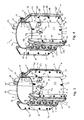
Figure 1 is a perspective view from above of a centralizer according to a first preferred embodiment of the invention, having a main body attached to a tubular member and with four abutments extending radially from the main body, each abutment having an adjustment mechanism including a movable blade member, each of which is in an extended position making contact with a surrounding bore; -
Figure 2 is a plan view from the side of the centralizer ofFigure 1 ; -
Figure 3 is a perspective view from above of the centralizer ofFigure 1 showing the blade members in a retracted position; -
Figure 4 a perspective view from above of the centralizer ofFigure 1 showing the blade members in an extended position; -
Figure 5 is a perspective view from above of the centralizer ofFigure 1 showing the blade members in a retracted position; -
Figure 6 is a cross-sectional view along the line VI-VI ofFigure 5 ; -
Figure 7 is a cross-sectional view along the line VII-VII ofFigure 1 ; -
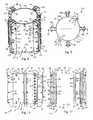
Figure 8 is a perspective view from above of a centralizer according to a second preferred embodiment of the invention, having a main body for attaching to a tubular member and with four abutments extending radially from the main body, each abutment having an adjustment mechanism including a movable blade member, each of which is in a retracted position; -
Figure 9 is a plan view from above of the centralizer ofFigure 8 ; -
Figure 10 is a side view of the centralizer ofFigure 8 ; -
Figure 11 is a cross-sectional view along the line XI-XI ofFigure 9 ; -
Figure 12 is a plan view from above of a deployment collar for temporary attachment to the centralizer ofFigure 8 when the main body of the centralizer is to be attached to a tubular member; -
Figure 13 is a side view of the deployment collar ofFigure 12 along the line XIII-XIII ofFigure 12 ; -
Figure 14 is a cross-sectional view along the line XIV-XIV ofFigure 12 ; -
Figure 15 is a side view of a centralizer deployment assembly according to a third preferred embodiment of the invention, composed of the deployment collar ofFigure 12 connected to an upper end of the centralizer ofFigure 8 ; -
Figure 16 is a cross section view through the centralizer deployment assembly ofFigure 15 , showing one of the abutments and a longitudinal hydraulic ram of the deployment mechanism for activating a wedging member of the adjustment mechanism; -
Figure 17 is a perspective view from above of the centralizer deployment assembly ofFigure 15 , showing the blade members in a retracted position; and -
Figure 18 a perspective view from above of the centralizer deployment assembly ofFigure 15 , showing the blade members in an extended position. -
Figures 1 and 2 show a centralizer 1 according to a first preferred embodiment of the present invention. The centralizer 1 is designed to locate between atubular member 5, for example a conductor or a casing string, and abore 7, for example a platform guide located either just above or just below the splash zone, in order to reduce conductor movement to a minimum. - The centralizer 1 comprises a
main body 2, which in this example is in the form of a steel split central tube defining alongitudinal axis 4 of the centralizer 1. Thecentral tube 2 is formed from twosemi-cylindrical tube portions flange 11 extending radially outwards from each of the four longitudinally extendingfree edges 12 of thetube portions flanges 11 are used to secure the twotube portions central tube 2 to be clamped around the innertubular member 5. On one side of thecentral tube 2, one pair offlanges 11 supports at each of its longitudinal ends 15, 17 ahinge mechanism hinge mechanism cylinder halves tubular member 5. - After clamping of the
central tube 2 around the innertubular member 5, both pairs offlanges 11 are then secured together using suitable fastening means such asnuts 14 andbolts 16 which pass through aligned holes (not shown) in theflanges 11, as shown most clearly inFigure 3 . - The
central tube 2 should, ideally, have an inner diameter that is approximately equal to an outer diameter of thetubular member 5 so that, when thecentral tube 2 is clamped around the tubular member, it may be fastened to grip tightly around thetubular member 5 so that it remains in position and does not slide longitudinally along the tubular member. - Four longitudinally extending fin-
like abutments 18 are spaced apart around themain body 2. Each abutment extends radially outwards from anexternal surface 20 of thecentral tube 2. Theabutments 18 extend the complete length of thecentral tube 2 and, in this embodiment, first and second, or upper and lower,abutment end portions central tube 2, as shown most clearly inFigure 2 . - A series of guide members or
fairleads 30 also project outwards from theexternal surface 20 of thecentral tube 2, the function of which will be described later. There are foursuch guide members 30, each guide member being located near and associated with one of theabutments 18. - The arrangement of
abutments 18 andguide members 30 is such that there are twoabutments 18 and twoguide members 30 extending from each of thetube portions abutments 18 are positioned equidistantly around thecentral tube 2 so as to form two opposing pairs ofabutments 18. - As shown in
Figures 3 to 7 , each of theabutments 18 includes guidingmounts 3 and an outermovable member 34 and a movable inner wedgingmember 36 which cooperate with each other such that the position of the outer movable member is radially adjustable. The movement of thesemembers parallel guide plates 32 between which the outer and innermovable members - The
guide plates 32 extend parallel to each other and parallel to thelongitudinal axis 4 beyond the upper andlower edges semi-cylindrical tube portions abutment end portions outer edge 31 to aid insertion of the centralizer 1 into thebore 7. Theguide plates 32 are spaced apart by a distance approximately equal to the width of themovable members movable members guide plates 32. - The innermost movable member is a wedging
member 36, most clearly shown inFigures 6 and 7 , and includes a flatlongitudinal edge 38 that is in sliding contact with theexternal surface 20 of thecentral tube 2 and a second opposing radially outwards edge that includes a series of ramped surfaces 42. The ramped surfaces 42 are inclined with respect to thelongitudinal axis 4 of the centralizer 1 and, in this embodiment, each of the ramped surfaces 42 slopes downwards and inwards with respect to thecentral tube 2 when the axis is vertically oriented, as in the drawings. Relatively short separating steps 44 extend between alower end 46 of one rampedsurface 42 and anupper end 48 of an adjacent rampedsurface 42 and, as such, thesteps 44 extend generally perpendicular to the ramped surfaces 42 and transverse to the flatlongitudinal edge 38. - The outermost movable member is a radially
movable blade 34 that includes a first radially inwards edge having a series ofinclined surfaces 52 and separatingsteps 54 that correspond and engage with the ramped surfaces 42 and separatingsteps 44 of the wedgingmember 36. Theouter blade 34 also includes a flatlongitudinal edge 56 that forms an outer contact surface of thisblade 34. - As can be seen from the drawings, this arrangement provides a plurality of pairs of inclined mating surfaces 42, 52 separated by the separating steps 44, 54 and together with the guiding
plates 32, this constrains both the radial and longitudinal movement of the outermovable member 34, and therefore serves to retain the wedging member to the main body. - Both the wedging
member 36 andouter blade 34 are formed from the same thickness of steel plate material. The wedging member in this example is therefore also in the form of ablade 36, which is radially in-line with theouter blade 34. As will be explained in detail below, both these blade members together form part of an adjustment mechanism for making a radially adjustable abutting contact with anouter bore 7 inside of which the centralizer 1 is to be used. - When the inner wedging and
outer blades guide plates 32, the flatlongitudinal edge 56 of theouter blade 34 is parallel to the flatlongitudinal edge 38 of thewedging blade 36. - As shown in
Figures 4 and5 , each of theguide plates 32 includes a plurality ofholes holes 60, 60' is located proximate an outerlongitudinal edge 66 of each of theguide plates 32, as shown inFigure 4 . One of theseholes 60 is located towards the first, taperedupper end 22 of theguide plate 32 and the other one of these holes 60' is located towards the second, taperedlower end 24 of theguide plate 32. As shown inFigure 6 , a corresponding pair ofholes 72, 72' is formed in theouter blade 34. When theouter blade 34 is in a retracted position, as will be explained below, the pair ofholes 60, 60' in each of theguide plates 32 aligns with the pair ofholes 72, 72' in theouter blade 34. As shown inFigure 3 , atransportation bolt 74 may be located through the alignedholes nut 75 in order to secure theouter blade 34 in position with respect to theguide plates 32 during transportation and storage of the centralizer 1. - As shown in
Figure 4 , asingle hole 62 is located proximate a radiallyinner edge 76 of theguide plates 32, and towards theupper end 22 of each of theguide plates 32. As shown inFigure 7 , a correspondinghole 78 is formed in theinner wedging blade 36. When thewedging blade 36 is in a retracted position, as will be explained below, theseholes 62 in theguide plates 32 align with thehole 78 in thewedging blade 36. A wedgingmember release pin 80 is preferably a split pin secured at one end with acotter pin 13. Therelease pin 80 is located through the alignedholes guide plates 32 andinner wedging blade 36. The function of this release pin will be described further below. - As shown in
Figure 5 in dashed outline, a set ofholes 64 is located proximate theouter edge 66 of each of theguide plates 32. In this example, there are threesuch holes 64, spaced apart along the length of each guide plate. A corresponding series ofslots 82 is formed in theouter blade 34 so that, when theouter blade 34 is in a retracted position, afirst end 84 of each of theslots 82 aligns with the correspondinghole 64 and, when theouter blade 34 is in an extended position, asecond end 86 of each of theslots 82 aligns with thehole 64. A blade guide bolt passes through each of the alignedholes 64 andslots 82. The blade guide bolt includes a pin orshaft 87, ahead portion 89 at one end of the shaft and a lockingnut 97 that is secured to the other end of the shaft. When in position through theguide plates 32 and theouter blade 34, thehead portion 89 locates against anouter surface 91 of one of theguide plates 32 and the lockingnut 97 locates against anouter surface 93 of the other one of theguide plates 32. As such, thehead portion 89 and lockingnut 97 retain theguide bolt shaft 87 through theouter blade 34. - In this embodiment, and as shown most clearly in
Figures 3 and 4 , theguide members 30 each include anarm portion 92 that extends from theexternal surface 20 of thecentral tube 2 and aloop section 94 located at afree end 95 of thearm portion 92. In addition, the wedging member release pins 80 include aring portion 96 at one end of the release pin. When the release pin is located through theguide plates 32 and theouter blade 34 it is oriented such that thering portion 96 is located on the same side of theabutment fin 18 as thecorresponding guide member 30. - Flexible,
elongate release cables 98, in the form of a rope or wire, are fixed at theirends 99 to each of thering portions 96 of the wedging member release pins 80. Eachrelease cable 98 passes through theloop section 94 of thecorresponding guide member 30 and extends upwards beyond theupper end 26 of the centralizer 1. Typically therelease cable 98 runs up to the surface or up to a production platform (not shown). - To install the centralizer 1, the
central tube 2 is first clamped around an innertubular member 5, which in this example is a hollow conductor. Thetransportation bolts 74 are then removed so that the outer andinner blade members inner wedging blade 36 are aligned with the first and second ends 26, 28 of thecentral tube 2, and the flatlongitudinal edge 56 of theouter blade 34 protrudes only slightly from theouter edge 66 of theguide plates 32. - The
conductor 5 is then run and located in the desired position in the sea floor and platform structure. Because the outer andinner blade members bore 7, for example a conductor guide, so that thetubular member 5, for example a conductor, passes easily through the conductor guide. - Once the
conductor 5 is in the correct position, the centralizer 1 is lowered within the conductor guide bore 7 by means of steel ropes (not shown) attached to lugs 33. Therelease cables 98 are then pulled which causes the wedging member release pins 80 to be pulled out of theholes guide plates 32 andouter blade 34. By continued pulling on therelease cables 98, the wedging member release pins 80 may be retrieved to the surface or the production platform. - With the wedging member release pins 80 removed there is nothing preventing the
inner wedging blade 36 from dropping down under its own weight. As thewedging blade 36 drops, so that thelower end 83 of thewedging blade 36 extends beyond thelower end 28 of thecentral tube 2, the matching ramped andinclined surfaces wedging blade 36 andouter blade 34 slide over each other. Due to the angle of the ramped and inclined surfaces and the fact that the movement of thewedging blade 36 is constrained by the first flatlongitudinal edge 38 of the wedging blade sliding along theexternal surface 20 of thecentral tube 2, the downward movement of theinner wedging blade 36 causes radially outward movement of theouter blade 34. - The movement of the
outer blade 34 is, in turn, constrained by the sliding of theshafts 87 of the guide bolts along theslots 82, as the outer blade moves from the retracted to an extended position. The shafts and slots therefore comprise together with theparallel guide plates 32 the guiding mounts 3. In this example, the slots are inclined slightly so that as theouter blade 34 moves outwards there is also a small component of movement in the downwards direction. Theslots 82 are angled downwards and radially outwards preferably at between about 5° to 15° below horizontal, so that the outwards movement of theouter blade 34 is substantially in a radial direction. The angle of theslot 82 causes the outer blade to move downwards as well as outwards, so the movement of the outer blade is assisted, and not hindered, by gravity and the weight of the outer blade. - The
outer blades 34 move outwards until theouter contact surface 56 of theouter blade 34 contacts theinner surface 7 of the conductor guide. In this extended position, the flatlongitudinal edge 56 of theouter blade 34 protrudes significantly from theouter edge 66 of theguide plates 32. - In this embodiment, the mating ramped and
inclined surfaces wedging blade 36 andouter blade 34 are serrated in order to provide a securing means to prevent the outer blade from moving radially inwards. As such, each of the ramped andinclined surfaces angled teeth 85, as shown most clearly in the insert ofFigure 7 . Once the wedginginner blade 36 has dropped to its longitudinally extended position, the corresponding saw-tooth projections 85 on each of the ramped andinclined surfaces tooth projections 85 form a linear ratchet mechanism to prevent the outer andinner blades - Because the centralizer 1 includes four
abutments 18 spaced around the circumference of the centralizer 1, theguide plates 32 act to centralise theconductor 5 within the conductor guide bore 7 to some degree while the outer andinner blades outer blades 34 then further minimises the gap between the centralizer 1 and the conductor guide bore 7 to prevent or minimise lateral movement of theconductor 5 within the conductor guide. - Typically the loads and force directions on the
conductor 5 and the conductor guide are such that thewedging blade 36 will not be pushed in an upwards direction. As such, theouter blade 34 will always fill the gap between the centralizer 1 and the conductor guide bore 7 with minimum clearance and without preload on the centralizer 1 or guide. - Although in the above embodiment the wedging member release pins 80 were removed by the use of flexible,
elongate release cables 98, in other embodiments it may be preferable to use other release means to remove the wedging member release pins 80. For example, the release pins 80 may be removed by the use of remotely operated hydraulic cylinders (not shown). -
Figures 8 to 11 show various views of acentralizer 101 according to a second preferred embodiment of the present invention. Features which are the same as those of the first embodiment are indicated using the same reference numerals, and as such features work in the same way as those of the first embodiment, these will not be described again in full detail. Features which have been modified in some way as compared with the first embodiment are indicated using reference numerals incremented by 100, and will be described insofar the functioning of these features differs from the first embodiment. - As with the first embodiment, the
centralizer 101 is designed to locate between atubular member 5, for example a conductor, and abore 7 in order to reduce conductor movement to a minimum. As will be explained below, thecentralizer 101 is adapted to be used in more remote locations than the first embodiment, for example near the sea bed. - The second embodiment of
centralizer 101 differs from the first embodiment mainly in that each pair of guidingplates 132 is truncated at thetop end 122, and in that each guiding plate is provided with aclearance hole 58. The top ends 122 of the guidingplates 132 together present aligned uppermost surfaces 25 which lie just above and parallel with theupper edge 22 of the tubularmain body 102. These uppermost surfaces 25 of thecentralizer 101 provide a flat platform on which adeployment collar 10 is located. Thedeployment collar 10 is shown separately inFigures 12 to 14 . During installation of thecentralizer 101, thedeployment collar 10 is temporarily attached to thecentralizer 101 to form acentralizer deployment assembly 50, as illustrated inFigures 15 to 18 . - The
deployment collar 10 is substantially ring-shaped, having a split annularmain body 27 formed in twosemi-circular rings ring hinge 39 by which one pair of opposed ends 35, 35' of the half rings 23, 29 are joined. The hinge includes a pair of joiningplates 41 welded on opposite sides to one of the half rings 29 and a pivot, which is provided by abolt 45, fixed to theother half ring 23. Thebolt 45 which passes through aligned holes (not shown) in the joiningplates 41 and the rounded end 35' of onehalf ring 23 to engage with a nut 47. - The other pair of opposed ends 35 of the half rings may be connected and disconnected by means of a pair of locking
plates 43 welded on opposite sides to one of the half rings 29 and by a pair ofbolts 49 then extend through holes (not shown) in both thelocking plates 43 and one of the half ring ends 35 which slots between the locking plates when therings bolts 45 can then be tightened or released by means of a pair ofnuts 51 threaded on the bolts in order to place or remove the deployment ring around thetubular member 5 to which thecentralizer 101 is to be secured. - The
deployment collar 10 has a plurality ofsteel lifting brackets 53, in this example eight, each of which extends in an axial direction from anupper side 55 of the annularmain body 27. Each lifting bracket is topped by a liftinglug 57 by which the collar may be lowered into place, after assembling around thetubular member 5 and prior to connection to thecentralizer 101. Although not illustrated, steel ropes and shackles would, in use, be connected to each of the lifting lugs 57. A radial inner side of each liftingbracket 53 is provided with aroller 59 to minimise scraping and prevent snagging of thedeployment collar 10 on the tubular member as the collar is being lowered or raised. - Also on the
upper side 55 of the annularmain body 27 is provided a plurality ofcylinders 61, of ahydraulic ram actuator 40 having a longitudinallymovable piston 63, shown schematically inFigure 16 . In this example, there are foursuch actuators 40. These actuators are an activating mechanism for controllably applying a force in an axial direction away from the collar main body for activating a radial adjustment mechanism of the centralizer. In this example, this force is applied to themovable wedge plate 136. Parts of the activating mechanism not shown include hydraulic lines and associated hydraulic control equipment. The hydraulic lines will be connected atports 68 on each cylinder and routed throughapertures 69 in each liftingbracket 53 to be fixed to arouting bracket 71 extending upwards from theupper side 55 of the annularmain body 27. From the routing bracket, hydraulic lines may extend back to the surface, or may terminate at a manifold to which a remotely operated vehicle may be connected. - Two of the
actuators 40 for the activating mechanism are mounted to each of the half rings 23, 29, so the ram actuators are spaced equidistantly around the annularmain body 27 of thedeployment collar 10. As shown inFigure 16 , eachpiston 63 when activated moves axially downwardly through acorresponding clearance hole 65 in the flat plate of steel material forming thehalf ring - A plurality of latching mechanisms, in this example four, are provided around the ring of the collar
main body 27 for latching to and de-latching from theupper end 26 of the centralizer main body so that, in use, thedeployment collar 10 may be temporarily mounted to the centralizer. In this example, the latching mechanism includes a plurality ofram actuators 90 each having acylinder 73 and a tangentiallymovable piston 70. Each of the latching ram actuators is oriented in a circumferential direction, being mounted on a firststeel flange plate 77. A secondsteel flange plate 79 is provided on an opposite side of thefirst flange plate 77 from thecylinder 73. The first andsecond flange plates lower side 67 of the annularmain body 27. - Each pair of
flange plates flange plate Figure 15 , these clearance holes being aligned to receive thepiston 70 when the latching ram actuator is activated. Parts of the latching mechanism not shown include hydraulic lines, would be connected to inlet andoutlet ports 88 and associated hydraulic control equipment. The hydraulic lines will be routed back to therouting bracket 71. - The
deployment collar 10 also includes fourcameras 9, mounted on thelower side 67 of the collarmain body 27. Although electrical wiring to each camera is not illustrated, this wiring will be routed back to therouting bracket 71. - The
deployment collar 10 is lowered towards the centralizer with thepistons 70 of the latching rams 90 fully retracted into the correspondingcylinders 73. The separation between theflange plates plates 132, so that as thedeployment collar 10 is lowered towards theupper edges 25 of the guidingplates 132, theupper end 122 of each guidingplate 132 slots in between theflange plates deployment collar 10 relative to thecentralizer 101 may then be verified using thecamera 9. When correctly aligned, the latchingclearance holes 58 in the guidingplates 132 will be aligned with the clearance holes 83 in theflange plates - Once in place, the
latching mechanism 90 is used to temporarily secure thedeployment collar 10 to the centralizer, as shown inFigure 17 , thereby forming thecentralizer deployment assembly 50. When thelatching mechanism pistons 70 are extended, these pass through the latching holes 58 in each guidingmember 132 and through each of theclearance hole 83 in theflange plates movable wedge plate 136 is also shaped to accommodate thepiston 70, but does not engage with the piston, so that the wedge plate is free to be driven downwards by the activatingpiston 63 once the wedgingmember release pin 80 has been withdrawn, for example by a remotely operated vehicle. Alternatively, the force applied to themovable wedge plate 136 by thecylinder 73 could be sufficient to sheer through the pin. - As with the first embodiment 1, the
outer blade 134 then moves outwards with the meshed saw teeth providing a ratchet effect which, together with the ambient force of gravity on thewedge plate 136, prevents the outer blade from becoming disengaged with thebore 7 once theadjustable abutments 118 of thecentralizer 101 have been fully extended, as shown inFigure 18 . - During this operation, the four
cameras 9 can also be used to make a visual check that each of the outer blades contact surfaces 56 is making a proper contact with thebore 7. - The
pistons 75 can then be retracted, thereby releasing thedeployment collar 10 from thecentralizer 101. The deployment collar can then be pulled up to the surface, and, if necessary, disengaged from thetubular member 5. - Typically, the
centralizer 1, 101 will include fourabutments - The present invention, therefore, provides an improved centralizer, suitable for use in an oil or gas production installation, which minimises the clearance between inner tubular member and an outer bore such as a platform guide or outer tubular member or guide, and which, in particular, may be used to reduce to a minimum any conductor movement within a conductor guide.
Claims (17)
- A centralizer (1, 101) suitable for centralising a tubular member (5) within a bore (7), the centralizer comprising a main body (2, 102) adapted to be connectable around a tubular member (5) to be centralised, the main body defining a longitudinal axis (4) of the centralizer, and a plurality of longitudinally extending abutments (18, 118) spaced apart around the main body (2, 102), each abutment extending radially outwards from the main body for making abutting contact with said bore and at least one of said abutments having an adjustment mechanism (3, 103, 34, 134, 36, 136, 42) for making a radially adjustable abutting contact with said bore, said adjustment mechanism comprising a radially movable outer blade (34, 134) for making said abutting contact, a longitudinally movable wedging member (36, 136) located between the outer blade and the main body (2, 102) for moving the outer blade radially into said abutting contact, at least one guiding mount (3, 103) for guiding said radial movement of the outer blade, and at least one longitudinally extending ramp surface (42), said ramp surface being inclined with respect to said axis (4), wherein:- the outer blade (34, 134) is constrained to move in a substantially radial direction by said at least one guiding mount (3, 103); and- the wedging member is constrained between the outer blade and the main body (2, 102) to move in a substantially longitudinal direction, the wedging member and said at least one ramp surface being configured to engage with one another such that as the wedging member moves longitudinally, the wedging member causes the outer blade to move radially,
characterized in that the arrangement of the wedging member (36, 136) and the outer blade (34, 134) is such that when the longitudinal axis (4) is substantially vertical, the weight of the wedging member automatically causes the wedging member to drop, thereby moving the outer blade in said radially outwards direction. - A centralizer (1, 101) as claimed in Claim 1, in which the wedging member (36, 136) and said ramp surface (42) have therebetween mating surfaces (42, 52) including said at least one ramp surface, said mating surfaces being inclined relative to said longitudinal axis (4) so that said movement of the wedging member (36, 136) in a first longitudinal direction causes said movement of the outer blade (34, 134) in a radially outwards direction as the wedging member moves relative to said ramp surface, there being a plurality of pairs of said inclined mating surfaces, said pairs being spaced longitudinally apart and being separated by substantially radially extending steps in each of said mating surfaces.
- A centralizer (1, 101) as claimed in Claim 2, in which said at least one guiding mount comprises a pair of guiding plates and said plurality of pairs of said inclined mating surfaces and said plurality of separating steps, together with said pair of said guiding plates, serve to retain the wedging member to the main body (2, 102).
- A centralizer (1, 101) as claimed in any preceding claim, in which at least one of the wedging member (36, 136) and the outer blade (34, 134) comprise securing means (85) to prevent movement of the wedging member in a longitudinal direction in which the wedging member causes or permits the outer blade to move radially inwards, said securing means being provided on opposing surfaces (42, 52) between the wedging member (36, 136) and ramp surface said opposing surfaces being textured with a saw-tooth profile (85) such that the opposing surfaces engage to prevent movement of the wedging member in said longitudinal direction in which the wedging member causes or permits the outer blade to move radially inwards but does not prevent movement in an opposite longitudinal direction.
- A centralizer (1, 101) as claimed in any preceding claim, in which said at least one guiding mount (3, 103) comprises a pair of plates (32, 132), said plates extending radially outwards from the main body (2, 102), the wedging member and the outer blade being mounted between said pair of plates.
- A centralizer (1, 101) as claimed in Claim 5, in which the outer blade (34, 134) is mounted to the pair of plates (32, 132) in such a way as to limit the extent of radial movement of the outer blade from a retracted position, nearest the main body (2, 102), to an extended position, furthest from the main body.
- A centralizer (1, 101) as claimed in Claim 6, in which the outer blade (34, 134) includes a slot (82), and a pin (87) carried by the pair of plates (32, 132) extends through the slot so as to adjustably mount the outer blade to the plates.
- A centralizer (1, 101) as claimed in any preceding claim, in which the centralizer further comprises a wedging member release means (13, 62, 78, 80) connectable to said wedging member (36, 136), said release means retaining the wedging member in a first, retracted position and preventing the wedging member moving in a longitudinal direction under gravity.
- A centralizer (1, 101) as claimed in Claim 8, in which the wedging member (36, 136) and the outer blade (34, 134) are mounted between a pair of plates (32, 132), and the wedging member release means comprises a hole (78) in the wedging member, a corresponding hole (62) in at least one of the plates and a removable wedging member release pin (80) extending through said holes in the wedging member and at least one of the plates.
- A centralizer (1, 101) as claimed in any preceding claim, in which the centralizer further comprises outer blade release means (60, 60' 72, 72', 74, 75) connectable to said wedging member (36, 136) and the outer blade (34, 134), said release means retaining the wedging member in a first, retracted position and preventing the wedging member moving in a longitudinal direction under gravity.
- A centralizer (1, 101) as claimed in Claim 10, in which the wedging member and the outer blade are mounted between a pair of plates (32, 132), and the outer blade release means comprises a hole (72, 72') in the outer blade, a corresponding hole (60, 60') in at least one of the plates (32, 132) and a removable outer blade release pin (74, 75) extending through said holes in the outer blade and at least one of the plates.
- A deployment collar (10) for temporary mounting to a substantially cylindrical centralizer (101) for centralising a tubular member (5) within a bore (7), the deployment collar comprising a ring-like main body (27) defining a longitudinal axis (104) of the deployment collar and having mounted to the collar main body (27) a latching mechanism (70, 73, 77, 79, 90) and an activating mechanism (40, 61, 63), wherein:- the latching mechanism is provided around the collar main body (27) for latching to and de-latching from an upper end (26) of a centralizer so that, in use, the deployment collar may be temporarily mounted to said centralizer (101); and- the activating mechanism includes at least one actuator (40), said actuator being configured, in use, to applying a force in an axial direction for activating a radial adjustment mechanism of said centralizer (101).
- A deployment collar (10) as claimed in Claim 12, in which the latching mechanism comprises at least one hydraulically or electrically operable ram actuators (90), said ram actuators including a piston (70) for engaging and disengaging with said centralizer (101), the piston being movable in a tangential direction relative to said axis (104) of the deployment collar as the centralizer deployment assembly latches and de-latches from said centralizer (101).
- A deployment collar (10) as claimed in Claim 12 or Claim 13, in which said at least one actuator of the activating mechanism includes a hydraulically or electrically operable ram actuator (40), said ram actuator including a piston (63), the piston being movable in a direction parallel with said axis (104) of the deployment collar as the centralizer deployment assembly activates the radial adjustment mechanism of said centralizer (101).
- A centralizer deployment assembly (50) comprising a centralizer (101) suitable for centralising a tubular member (5) within a bore (7), and a deployment collar (10) for temporary mounting to said centralizer when said centralizer is to be connected to said tubular member (5), the centralizer (101) being as claimed in any one of Claims 1 to 11 and the deployment collar (10) being as claimed in any one of Claims 12 to 14, wherein the deployment collar is temporarily mountable to said centralizer by means of the latching mechanism (70, 73, 77, 79, 90) in such a way that said activating mechanism (40, 61, 63) is configured relative to the centralizer to activate the wedging member (136) of an adjustment mechanism of one of said abutments (118) in order to make said radially adjustable abutting contact of said abutment with said bore.
- A method of using a centralizer (1, 101) to centralise a tubular member (5) within a bore (7), the centralizer being as claimed in any one of Claims 1 to 11, the method comprising the steps of:- fixing the main body (2, 102) of the centralizer to the tubular member (5) to be centralised;- inserting the tubular member (5) into the bore (7), the bore presenting a gap between the main body (2, 102) and the bore and the abutments (18, 118) extending partially across said gap so that the centralizer is free to move axially in said bore; and- moving the wedging member (36, 136) in a substantially longitudinal direction such that the wedging member and said at least one ramp surface (42) engage with one another thereby causing the outer blade (34, 134) to move radially outwards into contact with the bore to centralise the tubular member (5) within the bore (7).
- A method of using a centralizer deployment assembly (50) to centralise a tubular member (5) within a bore (7), the centralizer deployment assembly being as claimed in Claim 15, the method comprising the steps of:- fixing the main body (102) of the centralizer (101) to the tubular member (5) to be centralised;- inserting the tubular member (5) into the bore (7), the bore presenting a gap between the main body (102) and the bore and the abutments (118) extending partially across said gap so that the centralizer is free to move axially in said bore;- inserting the deployment collar (10) into the bore between the tubular member and the bore;- using the latching mechanism to temporarily mount the deployment collar (10) to the centralizer (101) in such a way that said activating mechanism (40, 61, 63) is located to activate the wedging member (136) of a corresponding adjustment mechanism;- using said activating mechanism to move the wedging member in an axial direction so that the wedging member engages with the ramp surface (42), thereby causing the outer blade (134) to move radially outwards into contact with the bore to centralise the tubular member (5) within the bore (7);- using the latching mechanism (70, 73, 77, 79, 90) to dismount the deployment collar (10) from the centralizer (101); and- removing the deployment collar from the bore (7).
Applications Claiming Priority (1)
| Application Number | Priority Date | Filing Date | Title |
|---|---|---|---|
| GBGB1116236.9A GB201116236D0 (en) | 2011-09-20 | 2011-09-20 | Centralizer |
Publications (3)
| Publication Number | Publication Date |
|---|---|
| EP2573315A2 true EP2573315A2 (en) | 2013-03-27 |
| EP2573315A3 EP2573315A3 (en) | 2015-11-18 |
| EP2573315B1 EP2573315B1 (en) | 2018-11-07 |
Family
ID=44937562
Family Applications (1)
| Application Number | Title | Priority Date | Filing Date |
|---|---|---|---|
| EP12185143.0A Not-in-force EP2573315B1 (en) | 2011-09-20 | 2012-09-20 | Centralizer |
Country Status (4)
| Country | Link |
|---|---|
| EP (1) | EP2573315B1 (en) |
| AU (1) | AU2012227158A1 (en) |
| DK (1) | DK2573315T3 (en) |
| GB (3) | GB201116236D0 (en) |
Cited By (3)
| Publication number | Priority date | Publication date | Assignee | Title |
|---|---|---|---|---|
| EP3959412A1 (en) * | 2019-04-25 | 2022-03-02 | South Offshore | Wedging device |
| CN115853501A (en) * | 2022-12-28 | 2023-03-28 | 基康仪器股份有限公司 | Detachable flexible inclinometer positioning guide wheel assembly structure |
| CN116808883A (en) * | 2023-06-14 | 2023-09-29 | 江苏浚和建设工程有限公司 | An intelligent soot spraying machine for building construction |
Families Citing this family (3)
| Publication number | Priority date | Publication date | Assignee | Title |
|---|---|---|---|---|
| GB2518417A (en) * | 2013-09-20 | 2015-03-25 | Hhr Entpr Ltd | A device for protecting a conductor passing through a guide on a sea based oil drilling platform |
| GB201915215D0 (en) | 2019-10-21 | 2019-12-04 | Mako Offshore Ltd | Conductor assembly and methods |
| CN111005377B (en) * | 2019-12-26 | 2021-07-27 | 黑龙江省八达路桥建设有限公司 | Drilling tool supporting limiting descending device for bored pile construction |
Citations (1)
| Publication number | Priority date | Publication date | Assignee | Title |
|---|---|---|---|---|
| GB2381280A (en) | 2001-10-23 | 2003-04-30 | Uwg Ltd | Adjustable centraliser with separate control tool |
Family Cites Families (5)
| Publication number | Priority date | Publication date | Assignee | Title |
|---|---|---|---|---|
| GB2277336B (en) * | 1993-04-06 | 1996-07-24 | Uwg Ltd | Centraliser |
| US6513223B1 (en) * | 2000-05-30 | 2003-02-04 | Tesco Corporation | Method for installing a centralizer retaining collar and outer sleeve |
| GB0218312D0 (en) * | 2002-08-07 | 2002-09-11 | Paramode Ltd | An adjustable centralising device |
| US7104318B2 (en) * | 2004-04-07 | 2006-09-12 | Plexus Ocean Systems, Ltd. | Self-contained centralizer system |
| GB2417505B (en) * | 2004-08-28 | 2008-06-25 | U W G Ltd | Centraliser |
-
2011
- 2011-09-20 GB GBGB1116236.9A patent/GB201116236D0/en not_active Ceased
-
2012
- 2012-09-18 AU AU2012227158A patent/AU2012227158A1/en not_active Abandoned
- 2012-09-20 EP EP12185143.0A patent/EP2573315B1/en not_active Not-in-force
- 2012-09-20 DK DK12185143.0T patent/DK2573315T3/en active
- 2012-09-20 GB GB1216828.2A patent/GB2494991B/en not_active Expired - Fee Related
- 2012-09-20 GB GB1216831.6A patent/GB2494994A/en not_active Withdrawn
Patent Citations (1)
| Publication number | Priority date | Publication date | Assignee | Title |
|---|---|---|---|---|
| GB2381280A (en) | 2001-10-23 | 2003-04-30 | Uwg Ltd | Adjustable centraliser with separate control tool |
Cited By (3)
| Publication number | Priority date | Publication date | Assignee | Title |
|---|---|---|---|---|
| EP3959412A1 (en) * | 2019-04-25 | 2022-03-02 | South Offshore | Wedging device |
| CN115853501A (en) * | 2022-12-28 | 2023-03-28 | 基康仪器股份有限公司 | Detachable flexible inclinometer positioning guide wheel assembly structure |
| CN116808883A (en) * | 2023-06-14 | 2023-09-29 | 江苏浚和建设工程有限公司 | An intelligent soot spraying machine for building construction |
Also Published As
| Publication number | Publication date |
|---|---|
| EP2573315B1 (en) | 2018-11-07 |
| DK2573315T3 (en) | 2019-01-28 |
| EP2573315A3 (en) | 2015-11-18 |
| GB201116236D0 (en) | 2011-11-02 |
| GB2494994A (en) | 2013-03-27 |
| GB201216828D0 (en) | 2012-11-07 |
| AU2012227158A1 (en) | 2013-04-04 |
| GB2494991A (en) | 2013-03-27 |
| GB201216831D0 (en) | 2012-11-07 |
| GB2494991B (en) | 2015-12-09 |
Similar Documents
| Publication | Publication Date | Title |
|---|---|---|
| EP2573315B1 (en) | Centralizer | |
| US5437518A (en) | Device for mounting a flexible line comprising a curvature limiter | |
| EP2238378B1 (en) | Tool for connecting pipelines | |
| US11248447B2 (en) | Moving tools on offshore structures with a walking carriage | |
| EP2281997A2 (en) | Split tubular support device | |
| US4024718A (en) | Subsea cable apparatus and method of handling same | |
| CN1860283A (en) | Method for installing and connecting a sub-sea riser | |
| US9598832B2 (en) | Assembly for mooring a pile with a mooring line and method implemented with said assembly | |
| EP3631266B1 (en) | Method and system for laying a submarine pipeline | |
| US11708727B2 (en) | Connection system for a marine drilling riser | |
| MX2013001352A (en) | Control line installation unit. | |
| EP4394130A2 (en) | Subsea foundation | |
| GB2494993A (en) | Deployment collar for a centralizer | |
| WO2024121579A1 (en) | A latch mechanism for a female connector of a subsea assembly | |
| US9982495B1 (en) | Tubular handling assembly and method | |
| EP1871973A1 (en) | Flexible riser and method for pulling-in and hanging up thereof | |
| WO2015093969A1 (en) | Method and machinery for operations in or through a tubular structure |
Legal Events
| Date | Code | Title | Description |
|---|---|---|---|
| PUAI | Public reference made under article 153(3) epc to a published international application that has entered the european phase |
Free format text: ORIGINAL CODE: 0009012 |
|
| AK | Designated contracting states |
Kind code of ref document: A2 Designated state(s): AL AT BE BG CH CY CZ DE DK EE ES FI FR GB GR HR HU IE IS IT LI LT LU LV MC MK MT NL NO PL PT RO RS SE SI SK SM TR |
|
| AX | Request for extension of the european patent |
Extension state: BA ME |
|
| RAP1 | Party data changed (applicant data changed or rights of an application transferred) |
Owner name: CLAXTON ENGINEERING SERVICES LIMITED |
|
| RIC1 | Information provided on ipc code assigned before grant |
Ipc: E21B 17/10 20060101AFI20150624BHEP |
|
| PUAL | Search report despatched |
Free format text: ORIGINAL CODE: 0009013 |
|
| AK | Designated contracting states |
Kind code of ref document: A3 Designated state(s): AL AT BE BG CH CY CZ DE DK EE ES FI FR GB GR HR HU IE IS IT LI LT LU LV MC MK MT NL NO PL PT RO RS SE SI SK SM TR |
|
| AX | Request for extension of the european patent |
Extension state: BA ME |
|
| RIC1 | Information provided on ipc code assigned before grant |
Ipc: E21B 17/10 20060101AFI20151015BHEP |
|
| 17P | Request for examination filed |
Effective date: 20160517 |
|
| RBV | Designated contracting states (corrected) |
Designated state(s): AL AT BE BG CH CY CZ DE DK EE ES FI FR GB GR HR HU IE IS IT LI LT LU LV MC MK MT NL NO PL PT RO RS SE SI SK SM TR |
|
| GRAP | Despatch of communication of intention to grant a patent |
Free format text: ORIGINAL CODE: EPIDOSNIGR1 |
|
| STAA | Information on the status of an ep patent application or granted ep patent |
Free format text: STATUS: GRANT OF PATENT IS INTENDED |
|
| INTG | Intention to grant announced |
Effective date: 20180418 |
|
| GRAJ | Information related to disapproval of communication of intention to grant by the applicant or resumption of examination proceedings by the epo deleted |
Free format text: ORIGINAL CODE: EPIDOSDIGR1 |
|
| STAA | Information on the status of an ep patent application or granted ep patent |
Free format text: STATUS: REQUEST FOR EXAMINATION WAS MADE |
|
| GRAR | Information related to intention to grant a patent recorded |
Free format text: ORIGINAL CODE: EPIDOSNIGR71 |
|
| GRAS | Grant fee paid |
Free format text: ORIGINAL CODE: EPIDOSNIGR3 |
|
| STAA | Information on the status of an ep patent application or granted ep patent |
Free format text: STATUS: GRANT OF PATENT IS INTENDED |
|
| INTC | Intention to grant announced (deleted) | ||
| INTG | Intention to grant announced |
Effective date: 20180830 |
|
| GRAA | (expected) grant |
Free format text: ORIGINAL CODE: 0009210 |
|
| STAA | Information on the status of an ep patent application or granted ep patent |
Free format text: STATUS: THE PATENT HAS BEEN GRANTED |
|
| AK | Designated contracting states |
Kind code of ref document: B1 Designated state(s): AL AT BE BG CH CY CZ DE DK EE ES FI FR GB GR HR HU IE IS IT LI LT LU LV MC MK MT NL NO PL PT RO RS SE SI SK SM TR |
|
| REG | Reference to a national code |
Ref country code: GB Ref legal event code: FG4D |
|
| REG | Reference to a national code |
Ref country code: CH Ref legal event code: EP Ref country code: AT Ref legal event code: REF Ref document number: 1062263 Country of ref document: AT Kind code of ref document: T Effective date: 20181115 |
|
| REG | Reference to a national code |
Ref country code: IE Ref legal event code: FG4D |
|
| REG | Reference to a national code |
Ref country code: DE Ref legal event code: R096 Ref document number: 602012053111 Country of ref document: DE |
|
| REG | Reference to a national code |
Ref country code: DK Ref legal event code: T3 Effective date: 20190123 |
|
| REG | Reference to a national code |
Ref country code: NL Ref legal event code: FP |
|
| REG | Reference to a national code |
Ref country code: LT Ref legal event code: MG4D |
|
| REG | Reference to a national code |
Ref country code: AT Ref legal event code: MK05 Ref document number: 1062263 Country of ref document: AT Kind code of ref document: T Effective date: 20181107 |
|
| REG | Reference to a national code |
Ref country code: NO Ref legal event code: T2 Effective date: 20181107 |
|
| PG25 | Lapsed in a contracting state [announced via postgrant information from national office to epo] |
Ref country code: IS Free format text: LAPSE BECAUSE OF FAILURE TO SUBMIT A TRANSLATION OF THE DESCRIPTION OR TO PAY THE FEE WITHIN THE PRESCRIBED TIME-LIMIT Effective date: 20190307 Ref country code: FI Free format text: LAPSE BECAUSE OF FAILURE TO SUBMIT A TRANSLATION OF THE DESCRIPTION OR TO PAY THE FEE WITHIN THE PRESCRIBED TIME-LIMIT Effective date: 20181107 Ref country code: AT Free format text: LAPSE BECAUSE OF FAILURE TO SUBMIT A TRANSLATION OF THE DESCRIPTION OR TO PAY THE FEE WITHIN THE PRESCRIBED TIME-LIMIT Effective date: 20181107 Ref country code: LV Free format text: LAPSE BECAUSE OF FAILURE TO SUBMIT A TRANSLATION OF THE DESCRIPTION OR TO PAY THE FEE WITHIN THE PRESCRIBED TIME-LIMIT Effective date: 20181107 Ref country code: LT Free format text: LAPSE BECAUSE OF FAILURE TO SUBMIT A TRANSLATION OF THE DESCRIPTION OR TO PAY THE FEE WITHIN THE PRESCRIBED TIME-LIMIT Effective date: 20181107 Ref country code: ES Free format text: LAPSE BECAUSE OF FAILURE TO SUBMIT A TRANSLATION OF THE DESCRIPTION OR TO PAY THE FEE WITHIN THE PRESCRIBED TIME-LIMIT Effective date: 20181107 Ref country code: BG Free format text: LAPSE BECAUSE OF FAILURE TO SUBMIT A TRANSLATION OF THE DESCRIPTION OR TO PAY THE FEE WITHIN THE PRESCRIBED TIME-LIMIT Effective date: 20190207 Ref country code: HR Free format text: LAPSE BECAUSE OF FAILURE TO SUBMIT A TRANSLATION OF THE DESCRIPTION OR TO PAY THE FEE WITHIN THE PRESCRIBED TIME-LIMIT Effective date: 20181107 |
|
| PG25 | Lapsed in a contracting state [announced via postgrant information from national office to epo] |
Ref country code: PT Free format text: LAPSE BECAUSE OF FAILURE TO SUBMIT A TRANSLATION OF THE DESCRIPTION OR TO PAY THE FEE WITHIN THE PRESCRIBED TIME-LIMIT Effective date: 20190307 Ref country code: AL Free format text: LAPSE BECAUSE OF FAILURE TO SUBMIT A TRANSLATION OF THE DESCRIPTION OR TO PAY THE FEE WITHIN THE PRESCRIBED TIME-LIMIT Effective date: 20181107 Ref country code: SE Free format text: LAPSE BECAUSE OF FAILURE TO SUBMIT A TRANSLATION OF THE DESCRIPTION OR TO PAY THE FEE WITHIN THE PRESCRIBED TIME-LIMIT Effective date: 20181107 Ref country code: GR Free format text: LAPSE BECAUSE OF FAILURE TO SUBMIT A TRANSLATION OF THE DESCRIPTION OR TO PAY THE FEE WITHIN THE PRESCRIBED TIME-LIMIT Effective date: 20190208 Ref country code: RS Free format text: LAPSE BECAUSE OF FAILURE TO SUBMIT A TRANSLATION OF THE DESCRIPTION OR TO PAY THE FEE WITHIN THE PRESCRIBED TIME-LIMIT Effective date: 20181107 |
|
| PG25 | Lapsed in a contracting state [announced via postgrant information from national office to epo] |
Ref country code: CZ Free format text: LAPSE BECAUSE OF FAILURE TO SUBMIT A TRANSLATION OF THE DESCRIPTION OR TO PAY THE FEE WITHIN THE PRESCRIBED TIME-LIMIT Effective date: 20181107 Ref country code: PL Free format text: LAPSE BECAUSE OF FAILURE TO SUBMIT A TRANSLATION OF THE DESCRIPTION OR TO PAY THE FEE WITHIN THE PRESCRIBED TIME-LIMIT Effective date: 20181107 |
|
| REG | Reference to a national code |
Ref country code: DE Ref legal event code: R097 Ref document number: 602012053111 Country of ref document: DE |
|
| PG25 | Lapsed in a contracting state [announced via postgrant information from national office to epo] |
Ref country code: SM Free format text: LAPSE BECAUSE OF FAILURE TO SUBMIT A TRANSLATION OF THE DESCRIPTION OR TO PAY THE FEE WITHIN THE PRESCRIBED TIME-LIMIT Effective date: 20181107 Ref country code: EE Free format text: LAPSE BECAUSE OF FAILURE TO SUBMIT A TRANSLATION OF THE DESCRIPTION OR TO PAY THE FEE WITHIN THE PRESCRIBED TIME-LIMIT Effective date: 20181107 Ref country code: RO Free format text: LAPSE BECAUSE OF FAILURE TO SUBMIT A TRANSLATION OF THE DESCRIPTION OR TO PAY THE FEE WITHIN THE PRESCRIBED TIME-LIMIT Effective date: 20181107 Ref country code: SK Free format text: LAPSE BECAUSE OF FAILURE TO SUBMIT A TRANSLATION OF THE DESCRIPTION OR TO PAY THE FEE WITHIN THE PRESCRIBED TIME-LIMIT Effective date: 20181107 |
|
| PLBE | No opposition filed within time limit |
Free format text: ORIGINAL CODE: 0009261 |
|
| STAA | Information on the status of an ep patent application or granted ep patent |
Free format text: STATUS: NO OPPOSITION FILED WITHIN TIME LIMIT |
|
| 26N | No opposition filed |
Effective date: 20190808 |
|
| PG25 | Lapsed in a contracting state [announced via postgrant information from national office to epo] |
Ref country code: SI Free format text: LAPSE BECAUSE OF FAILURE TO SUBMIT A TRANSLATION OF THE DESCRIPTION OR TO PAY THE FEE WITHIN THE PRESCRIBED TIME-LIMIT Effective date: 20181107 |
|
| PGFP | Annual fee paid to national office [announced via postgrant information from national office to epo] |
Ref country code: DE Payment date: 20190830 Year of fee payment: 8 Ref country code: FR Payment date: 20190729 Year of fee payment: 8 Ref country code: DK Payment date: 20190715 Year of fee payment: 8 Ref country code: NL Payment date: 20190903 Year of fee payment: 8 Ref country code: NO Payment date: 20190716 Year of fee payment: 8 |
|
| PGFP | Annual fee paid to national office [announced via postgrant information from national office to epo] |
Ref country code: GB Payment date: 20190703 Year of fee payment: 8 |
|
| PGFP | Annual fee paid to national office [announced via postgrant information from national office to epo] |
Ref country code: IT Payment date: 20190926 Year of fee payment: 8 |
|
| PG25 | Lapsed in a contracting state [announced via postgrant information from national office to epo] |
Ref country code: TR Free format text: LAPSE BECAUSE OF FAILURE TO SUBMIT A TRANSLATION OF THE DESCRIPTION OR TO PAY THE FEE WITHIN THE PRESCRIBED TIME-LIMIT Effective date: 20181107 |
|
| PG25 | Lapsed in a contracting state [announced via postgrant information from national office to epo] |
Ref country code: MC Free format text: LAPSE BECAUSE OF FAILURE TO SUBMIT A TRANSLATION OF THE DESCRIPTION OR TO PAY THE FEE WITHIN THE PRESCRIBED TIME-LIMIT Effective date: 20181107 |
|
| REG | Reference to a national code |
Ref country code: CH Ref legal event code: PL |
|
| PG25 | Lapsed in a contracting state [announced via postgrant information from national office to epo] |
Ref country code: LU Free format text: LAPSE BECAUSE OF NON-PAYMENT OF DUE FEES Effective date: 20190920 Ref country code: CH Free format text: LAPSE BECAUSE OF NON-PAYMENT OF DUE FEES Effective date: 20190930 Ref country code: LI Free format text: LAPSE BECAUSE OF NON-PAYMENT OF DUE FEES Effective date: 20190930 Ref country code: IE Free format text: LAPSE BECAUSE OF NON-PAYMENT OF DUE FEES Effective date: 20190920 |
|
| REG | Reference to a national code |
Ref country code: BE Ref legal event code: MM Effective date: 20190930 |
|
| PG25 | Lapsed in a contracting state [announced via postgrant information from national office to epo] |
Ref country code: BE Free format text: LAPSE BECAUSE OF NON-PAYMENT OF DUE FEES Effective date: 20190930 |
|
| REG | Reference to a national code |
Ref country code: DE Ref legal event code: R119 Ref document number: 602012053111 Country of ref document: DE |
|
| REG | Reference to a national code |
Ref country code: NO Ref legal event code: MMEP Ref country code: DK Ref legal event code: EBP Effective date: 20200930 |
|
| REG | Reference to a national code |
Ref country code: NL Ref legal event code: MM Effective date: 20201001 |
|
| GBPC | Gb: european patent ceased through non-payment of renewal fee |
Effective date: 20200920 |
|
| PG25 | Lapsed in a contracting state [announced via postgrant information from national office to epo] |
Ref country code: CY Free format text: LAPSE BECAUSE OF FAILURE TO SUBMIT A TRANSLATION OF THE DESCRIPTION OR TO PAY THE FEE WITHIN THE PRESCRIBED TIME-LIMIT Effective date: 20181107 |
|
| PG25 | Lapsed in a contracting state [announced via postgrant information from national office to epo] |
Ref country code: NL Free format text: LAPSE BECAUSE OF NON-PAYMENT OF DUE FEES Effective date: 20201001 |
|
| PG25 | Lapsed in a contracting state [announced via postgrant information from national office to epo] |
Ref country code: HU Free format text: LAPSE BECAUSE OF FAILURE TO SUBMIT A TRANSLATION OF THE DESCRIPTION OR TO PAY THE FEE WITHIN THE PRESCRIBED TIME-LIMIT; INVALID AB INITIO Effective date: 20120920 Ref country code: NO Free format text: LAPSE BECAUSE OF NON-PAYMENT OF DUE FEES Effective date: 20200930 Ref country code: MT Free format text: LAPSE BECAUSE OF FAILURE TO SUBMIT A TRANSLATION OF THE DESCRIPTION OR TO PAY THE FEE WITHIN THE PRESCRIBED TIME-LIMIT Effective date: 20181107 Ref country code: DE Free format text: LAPSE BECAUSE OF NON-PAYMENT OF DUE FEES Effective date: 20210401 Ref country code: FR Free format text: LAPSE BECAUSE OF NON-PAYMENT OF DUE FEES Effective date: 20200930 |
|
| PG25 | Lapsed in a contracting state [announced via postgrant information from national office to epo] |
Ref country code: GB Free format text: LAPSE BECAUSE OF NON-PAYMENT OF DUE FEES Effective date: 20200920 |
|
| PG25 | Lapsed in a contracting state [announced via postgrant information from national office to epo] |
Ref country code: IT Free format text: LAPSE BECAUSE OF NON-PAYMENT OF DUE FEES Effective date: 20200920 |
|
| PG25 | Lapsed in a contracting state [announced via postgrant information from national office to epo] |
Ref country code: DK Free format text: LAPSE BECAUSE OF NON-PAYMENT OF DUE FEES Effective date: 20200930 |
|
| PG25 | Lapsed in a contracting state [announced via postgrant information from national office to epo] |
Ref country code: MK Free format text: LAPSE BECAUSE OF FAILURE TO SUBMIT A TRANSLATION OF THE DESCRIPTION OR TO PAY THE FEE WITHIN THE PRESCRIBED TIME-LIMIT Effective date: 20181107 |