EP2573207A2 - Nickel oxide mitigation layer for vandium on thermal barrier coatings - Google Patents
Nickel oxide mitigation layer for vandium on thermal barrier coatings Download PDFInfo
- Publication number
- EP2573207A2 EP2573207A2 EP12183113A EP12183113A EP2573207A2 EP 2573207 A2 EP2573207 A2 EP 2573207A2 EP 12183113 A EP12183113 A EP 12183113A EP 12183113 A EP12183113 A EP 12183113A EP 2573207 A2 EP2573207 A2 EP 2573207A2
- Authority
- EP
- European Patent Office
- Prior art keywords
- gas turbine
- thermal barrier
- turbine engine
- barrier coating
- nio
- Prior art date
- Legal status (The legal status is an assumption and is not a legal conclusion. Google has not performed a legal analysis and makes no representation as to the accuracy of the status listed.)
- Withdrawn
Links
- 239000012720 thermal barrier coating Substances 0.000 title claims abstract description 81
- 230000000116 mitigating effect Effects 0.000 title claims abstract description 11
- 229910000480 nickel oxide Inorganic materials 0.000 title description 6
- GNRSAWUEBMWBQH-UHFFFAOYSA-N oxonickel Chemical compound [Ni]=O GNRSAWUEBMWBQH-UHFFFAOYSA-N 0.000 title description 6
- GNTDGMZSJNCJKK-UHFFFAOYSA-N divanadium pentaoxide Chemical compound O=[V](=O)O[V](=O)=O GNTDGMZSJNCJKK-UHFFFAOYSA-N 0.000 claims abstract description 42
- 239000010410 layer Substances 0.000 claims abstract description 38
- 238000000576 coating method Methods 0.000 claims abstract description 32
- 238000000034 method Methods 0.000 claims abstract description 31
- 239000011248 coating agent Substances 0.000 claims abstract description 30
- 229940078487 nickel acetate tetrahydrate Drugs 0.000 claims abstract description 23
- OINIXPNQKAZCRL-UHFFFAOYSA-L nickel(2+);diacetate;tetrahydrate Chemical compound O.O.O.O.[Ni+2].CC([O-])=O.CC([O-])=O OINIXPNQKAZCRL-UHFFFAOYSA-L 0.000 claims abstract description 23
- 239000012047 saturated solution Substances 0.000 claims abstract description 12
- 238000006243 chemical reaction Methods 0.000 claims abstract description 10
- 150000001875 compounds Chemical class 0.000 claims abstract description 10
- 239000007788 liquid Substances 0.000 claims abstract description 8
- 239000011253 protective coating Substances 0.000 claims abstract description 7
- 239000011241 protective layer Substances 0.000 claims abstract description 7
- 229910052720 vanadium Inorganic materials 0.000 claims description 23
- LEONUFNNVUYDNQ-UHFFFAOYSA-N vanadium atom Chemical compound [V] LEONUFNNVUYDNQ-UHFFFAOYSA-N 0.000 claims description 23
- 239000000243 solution Substances 0.000 claims description 15
- 238000012360 testing method Methods 0.000 claims description 15
- 238000010438 heat treatment Methods 0.000 claims description 9
- 229910000601 superalloy Inorganic materials 0.000 claims description 9
- PXHVJJICTQNCMI-UHFFFAOYSA-N nickel Substances [Ni] PXHVJJICTQNCMI-UHFFFAOYSA-N 0.000 claims description 8
- 230000003647 oxidation Effects 0.000 claims description 8
- 238000007254 oxidation reaction Methods 0.000 claims description 8
- 239000007787 solid Substances 0.000 claims description 7
- 239000000758 substrate Substances 0.000 claims description 7
- 238000011156 evaluation Methods 0.000 claims description 2
- 239000002244 precipitate Substances 0.000 claims description 2
- 230000035515 penetration Effects 0.000 claims 1
- 239000007921 spray Substances 0.000 claims 1
- 239000007789 gas Substances 0.000 description 52
- 239000000446 fuel Substances 0.000 description 30
- 230000007797 corrosion Effects 0.000 description 9
- 238000005260 corrosion Methods 0.000 description 9
- 239000000463 material Substances 0.000 description 9
- 239000004215 Carbon black (E152) Substances 0.000 description 8
- 229930195733 hydrocarbon Natural products 0.000 description 8
- 150000002430 hydrocarbons Chemical class 0.000 description 8
- 239000011777 magnesium Substances 0.000 description 8
- FYYHWMGAXLPEAU-UHFFFAOYSA-N Magnesium Chemical compound [Mg] FYYHWMGAXLPEAU-UHFFFAOYSA-N 0.000 description 7
- 229910052749 magnesium Inorganic materials 0.000 description 7
- 230000008569 process Effects 0.000 description 7
- 229910001233 yttria-stabilized zirconia Inorganic materials 0.000 description 6
- CSNNHWWHGAXBCP-UHFFFAOYSA-L Magnesium sulfate Chemical compound [Mg+2].[O-][S+2]([O-])([O-])[O-] CSNNHWWHGAXBCP-UHFFFAOYSA-L 0.000 description 4
- MCMNRKCIXSYSNV-UHFFFAOYSA-N Zirconium dioxide Chemical compound O=[Zr]=O MCMNRKCIXSYSNV-UHFFFAOYSA-N 0.000 description 4
- 238000010586 diagram Methods 0.000 description 4
- 238000005194 fractionation Methods 0.000 description 4
- 239000007792 gaseous phase Substances 0.000 description 4
- 239000000395 magnesium oxide Substances 0.000 description 4
- CPLXHLVBOLITMK-UHFFFAOYSA-N magnesium oxide Inorganic materials [Mg]=O CPLXHLVBOLITMK-UHFFFAOYSA-N 0.000 description 4
- AXZKOIWUVFPNLO-UHFFFAOYSA-N magnesium;oxygen(2-) Chemical compound [O-2].[Mg+2] AXZKOIWUVFPNLO-UHFFFAOYSA-N 0.000 description 4
- 238000012423 maintenance Methods 0.000 description 4
- 229910052751 metal Inorganic materials 0.000 description 4
- 239000002184 metal Substances 0.000 description 4
- PMZURENOXWZQFD-UHFFFAOYSA-L Sodium Sulfate Chemical class [Na+].[Na+].[O-]S([O-])(=O)=O PMZURENOXWZQFD-UHFFFAOYSA-L 0.000 description 3
- 238000009825 accumulation Methods 0.000 description 3
- 238000002485 combustion reaction Methods 0.000 description 3
- 230000000694 effects Effects 0.000 description 3
- 230000008595 infiltration Effects 0.000 description 3
- 238000001764 infiltration Methods 0.000 description 3
- 230000008018 melting Effects 0.000 description 3
- 238000002844 melting Methods 0.000 description 3
- 239000000203 mixture Substances 0.000 description 3
- 229910052759 nickel Inorganic materials 0.000 description 3
- 230000036961 partial effect Effects 0.000 description 3
- 230000001681 protective effect Effects 0.000 description 3
- 229910052938 sodium sulfate Inorganic materials 0.000 description 3
- LSGOVYNHVSXFFJ-UHFFFAOYSA-N vanadate(3-) Chemical compound [O-][V]([O-])([O-])=O LSGOVYNHVSXFFJ-UHFFFAOYSA-N 0.000 description 3
- RUDFQVOCFDJEEF-UHFFFAOYSA-N yttrium(III) oxide Inorganic materials [O-2].[O-2].[O-2].[Y+3].[Y+3] RUDFQVOCFDJEEF-UHFFFAOYSA-N 0.000 description 3
- XEEYBQQBJWHFJM-UHFFFAOYSA-N Iron Chemical group [Fe] XEEYBQQBJWHFJM-UHFFFAOYSA-N 0.000 description 2
- PNEYBMLMFCGWSK-UHFFFAOYSA-N aluminium oxide Inorganic materials [O-2].[O-2].[O-2].[Al+3].[Al+3] PNEYBMLMFCGWSK-UHFFFAOYSA-N 0.000 description 2
- 230000003466 anti-cipated effect Effects 0.000 description 2
- 230000015572 biosynthetic process Effects 0.000 description 2
- 239000000356 contaminant Substances 0.000 description 2
- 238000005336 cracking Methods 0.000 description 2
- 239000010779 crude oil Substances 0.000 description 2
- 238000005328 electron beam physical vapour deposition Methods 0.000 description 2
- 238000011065 in-situ storage Methods 0.000 description 2
- 229910052943 magnesium sulfate Inorganic materials 0.000 description 2
- 239000011159 matrix material Substances 0.000 description 2
- 230000007246 mechanism Effects 0.000 description 2
- 230000000149 penetrating effect Effects 0.000 description 2
- 230000000737 periodic effect Effects 0.000 description 2
- 235000011152 sodium sulphate Nutrition 0.000 description 2
- 150000003682 vanadium compounds Chemical class 0.000 description 2
- 206010067484 Adverse reaction Diseases 0.000 description 1
- 229910000951 Aluminide Inorganic materials 0.000 description 1
- 239000007832 Na2SO4 Substances 0.000 description 1
- QAOWNCQODCNURD-UHFFFAOYSA-L Sulfate Chemical compound [O-]S([O-])(=O)=O QAOWNCQODCNURD-UHFFFAOYSA-L 0.000 description 1
- NINIDFKCEFEMDL-UHFFFAOYSA-N Sulfur Chemical compound [S] NINIDFKCEFEMDL-UHFFFAOYSA-N 0.000 description 1
- QXZUUHYBWMWJHK-UHFFFAOYSA-N [Co].[Ni] Chemical compound [Co].[Ni] QXZUUHYBWMWJHK-UHFFFAOYSA-N 0.000 description 1
- 239000000654 additive Substances 0.000 description 1
- 230000001464 adherent effect Effects 0.000 description 1
- 230000002411 adverse Effects 0.000 description 1
- 230000006838 adverse reaction Effects 0.000 description 1
- 238000013459 approach Methods 0.000 description 1
- QVGXLLKOCUKJST-UHFFFAOYSA-N atomic oxygen Chemical compound [O] QVGXLLKOCUKJST-UHFFFAOYSA-N 0.000 description 1
- 230000015556 catabolic process Effects 0.000 description 1
- 229910010293 ceramic material Inorganic materials 0.000 description 1
- 229910017052 cobalt Inorganic materials 0.000 description 1
- 239000010941 cobalt Chemical group 0.000 description 1
- GUTLYIVDDKVIGB-UHFFFAOYSA-N cobalt atom Chemical group [Co] GUTLYIVDDKVIGB-UHFFFAOYSA-N 0.000 description 1
- 229910052593 corundum Inorganic materials 0.000 description 1
- 230000001351 cycling effect Effects 0.000 description 1
- 238000006731 degradation reaction Methods 0.000 description 1
- 238000009792 diffusion process Methods 0.000 description 1
- 239000010763 heavy fuel oil Substances 0.000 description 1
- 230000002401 inhibitory effect Effects 0.000 description 1
- 150000002484 inorganic compounds Chemical class 0.000 description 1
- 229910010272 inorganic material Inorganic materials 0.000 description 1
- 238000009434 installation Methods 0.000 description 1
- 230000003993 interaction Effects 0.000 description 1
- 229910052742 iron Inorganic materials 0.000 description 1
- 238000012986 modification Methods 0.000 description 1
- 230000004048 modification Effects 0.000 description 1
- 125000002524 organometallic group Chemical group 0.000 description 1
- TWNQGVIAIRXVLR-UHFFFAOYSA-N oxo(oxoalumanyloxy)alumane Chemical compound O=[Al]O[Al]=O TWNQGVIAIRXVLR-UHFFFAOYSA-N 0.000 description 1
- 229910052760 oxygen Inorganic materials 0.000 description 1
- 239000001301 oxygen Substances 0.000 description 1
- 238000010422 painting Methods 0.000 description 1
- 239000012071 phase Substances 0.000 description 1
- 150000004032 porphyrins Chemical class 0.000 description 1
- 230000002028 premature Effects 0.000 description 1
- 238000002203 pretreatment Methods 0.000 description 1
- 230000002250 progressing effect Effects 0.000 description 1
- 229910052761 rare earth metal Inorganic materials 0.000 description 1
- 230000002829 reductive effect Effects 0.000 description 1
- 239000011819 refractory material Substances 0.000 description 1
- 230000000717 retained effect Effects 0.000 description 1
- 239000011555 saturated liquid Substances 0.000 description 1
- 159000000000 sodium salts Chemical class 0.000 description 1
- 238000001179 sorption measurement Methods 0.000 description 1
- 229910052717 sulfur Inorganic materials 0.000 description 1
- 239000011593 sulfur Substances 0.000 description 1
- 150000003464 sulfur compounds Chemical class 0.000 description 1
- 238000004227 thermal cracking Methods 0.000 description 1
- QWVYNEUUYROOSZ-UHFFFAOYSA-N trioxido(oxo)vanadium;yttrium(3+) Chemical compound [Y+3].[O-][V]([O-])([O-])=O QWVYNEUUYROOSZ-UHFFFAOYSA-N 0.000 description 1
- 229910001845 yogo sapphire Inorganic materials 0.000 description 1
- 229910052727 yttrium Inorganic materials 0.000 description 1
- VWQVUPCCIRVNHF-UHFFFAOYSA-N yttrium atom Chemical group [Y] VWQVUPCCIRVNHF-UHFFFAOYSA-N 0.000 description 1
Images

Classifications
-
- C—CHEMISTRY; METALLURGY
- C23—COATING METALLIC MATERIAL; COATING MATERIAL WITH METALLIC MATERIAL; CHEMICAL SURFACE TREATMENT; DIFFUSION TREATMENT OF METALLIC MATERIAL; COATING BY VACUUM EVAPORATION, BY SPUTTERING, BY ION IMPLANTATION OR BY CHEMICAL VAPOUR DEPOSITION, IN GENERAL; INHIBITING CORROSION OF METALLIC MATERIAL OR INCRUSTATION IN GENERAL
- C23C—COATING METALLIC MATERIAL; COATING MATERIAL WITH METALLIC MATERIAL; SURFACE TREATMENT OF METALLIC MATERIAL BY DIFFUSION INTO THE SURFACE, BY CHEMICAL CONVERSION OR SUBSTITUTION; COATING BY VACUUM EVAPORATION, BY SPUTTERING, BY ION IMPLANTATION OR BY CHEMICAL VAPOUR DEPOSITION, IN GENERAL
- C23C18/00—Chemical coating by decomposition of either liquid compounds or solutions of the coating forming compounds, without leaving reaction products of surface material in the coating; Contact plating
- C23C18/02—Chemical coating by decomposition of either liquid compounds or solutions of the coating forming compounds, without leaving reaction products of surface material in the coating; Contact plating by thermal decomposition
- C23C18/12—Chemical coating by decomposition of either liquid compounds or solutions of the coating forming compounds, without leaving reaction products of surface material in the coating; Contact plating by thermal decomposition characterised by the deposition of inorganic material other than metallic material
- C23C18/1204—Chemical coating by decomposition of either liquid compounds or solutions of the coating forming compounds, without leaving reaction products of surface material in the coating; Contact plating by thermal decomposition characterised by the deposition of inorganic material other than metallic material inorganic material, e.g. non-oxide and non-metallic such as sulfides, nitrides based compounds
- C23C18/1208—Oxides, e.g. ceramics
- C23C18/1216—Metal oxides
-
- Y—GENERAL TAGGING OF NEW TECHNOLOGICAL DEVELOPMENTS; GENERAL TAGGING OF CROSS-SECTIONAL TECHNOLOGIES SPANNING OVER SEVERAL SECTIONS OF THE IPC; TECHNICAL SUBJECTS COVERED BY FORMER USPC CROSS-REFERENCE ART COLLECTIONS [XRACs] AND DIGESTS
- Y10—TECHNICAL SUBJECTS COVERED BY FORMER USPC
- Y10T—TECHNICAL SUBJECTS COVERED BY FORMER US CLASSIFICATION
- Y10T428/00—Stock material or miscellaneous articles
- Y10T428/12—All metal or with adjacent metals
- Y10T428/12493—Composite; i.e., plural, adjacent, spatially distinct metal components [e.g., layers, joint, etc.]
- Y10T428/12535—Composite; i.e., plural, adjacent, spatially distinct metal components [e.g., layers, joint, etc.] with additional, spatially distinct nonmetal component
- Y10T428/12611—Oxide-containing component
Definitions
- the present invention relates to a new process for forming an in situ layer of protective material over a thermal barrier coating ("TBC") used to protect the working components of a gas turbine engine and, in particular, to a new method for applying a sacrificial layer of material onto the TBC which effectively prevents the reaction of vanadium pentoxide with yttria-stabilized compounds in the TBC.
- TBC thermal barrier coating
- Turbine components particularly turbine blades, often comprise nickel-based superalloys which provide excellent resistance to creep, metal fatigue and corrosion, i.e., the principle degradation mechanisms in the hot sections of the gas turbine engine, particularly the combustion chamber and turbine.
- Significant advances in high-temperature applications have been made in recent years, including by General Electric, using different nickel- and cobalt-based superalloys to form the key components of gas turbine engines, particularly the combustor and augmentor sections of the engines.
- TBCs The mechanisms by which TBCs fail are also varied and complex, the most important being thermal-expansion stresses, metal oxidation and physical changes in the TBC composition and properties.
- Ceramic materials particularly yttria-stabilized zirconia (YSZ), are now widely used as a thermal barrier coating in TBC systems for gas turbine engines.
- YSZ yttria-stabilized zirconia
- the TBC used in the highest-temperature regions of the engines is deposited by electron beam physical vapor deposition (EBPVD) techniques that produce a grain structure capable of expanding and contracting without causing damaging stresses that lead to spallation.
- EBPVD electron beam physical vapor deposition
- an oxidation-resistant bond coat is often employed, usually in the form of MCrAlX (where M is iron, cobalt and/or nickel, and X is yttrium or another rare earth element) or a diffusion aluminide coating.
- M is iron, cobalt and/or nickel
- X is yttrium or another rare earth element
- a diffusion aluminide coating e.g., aluminum oxide or Al 2 O 3
- the service life of a TBC system is limited by spallation at or near the interfaces of the bond coat with the TBC.
- the monoclinic phase of zirconia as shown above (m-ZrO 2 ) is undesirable because it undergoes volume changes when thermally cycled, such as during the normal operation of the gas turbine engine. Such repeated cycling can lead to coating spallation and ultimately a potential catastrophic failure of critical engine components. It has been found that the problem of spallation may be accelerated by contaminants in the fuel being used to drive the gas turbine engine. That is, the hot corrosion is promoted by contaminants present in the hydrocarbon fuel and air mixture, particularly Middle East fuels containing even small amounts of vanadium. Vanadium is often found in residual fuel oils, as well as in some crude oils, typically in the form of a porphyrin or other organometallic complex. Inorganic compounds containing vanadium have also have been found in lower grade fuels.
- V 2 O 3 and V 2 O 4 (VO 2 ) are considered refractory materials that have melting points above 1500°C, and thus normally will pass through the gas turbine as part of the exhaust stream.
- Vanadium pentoxide, V 2 O 5 has a much lower melting point (in the range of about 650°C-670°C).
- V 2 O 5 is normally a liquid at typical gas turbine operating temperatures and tends to deposit on the surfaces of hot components ultimately causing hot corrosion and contributing to spallation.
- magnesium-containing compounds e.g., MgSO 4
- MgO magnesium oxide
- V 2 O 5 magnesium vanadate
- various residual sulfur compounds such as from sodium sulfates and SO 2 from the combustor fuel, tend to reduce the effectiveness of the MgO which preferentially reacts with the sulfur to form MgSO 4 , rather than with V 2 O 5 to form magnesium vanadate.
- magnesium-based compounds added to low-grade fuels while helping to reduce the corrosive effect of vanadium, can result in the accumulation of ash-like deposits on interior gas turbine parts, which requires periodic shutdown and maintenance of the gas turbine engine to remove the accumulated deposits.
- the accumulated ash includes both V 2 O 5 (vanadium pentoxide) and Na 2 SO 4 (sodium sulfate).
- the ash material which then forms a variety of sodium salts, causes fouling and corrosion of the hot gas path components due to the formation of low melting point reactive compounds containing vanadium.
- the fouling and corrosion over long periods of operation cause the metallic components to deteriorate or even fail, resulting in a need to shut down the entire gas turbine engine.
- the figures and accompanying text below describe a new method for providing a protective coating on gas turbine engine components comprising the steps of forming a saturated solution of nickel acetate tetrahydrate, applying a uniform thickness of the coating onto the thermal barrier coating of selected components of the gas turbine engine, and heat treating the coated component in air at a temperature sufficient to form an integral protective layer of NiO over the thermal barrier coating.
- the saturated solution of nickel-acetate tetrahydrate is applied as a liquid in an amount sufficient to form a uniform NiO layer over the thermal barrier coating with sufficient solubility at room temperature to penetrate into the microscopic cracks of the thermal barrier coating.
- the NiO layer thus forms a "sacrificial mitigation layer" that substantially inhibits the reaction between vanadium pentoxide and yttria-stabilized compounds present in the thermal barrier coating by reacting with vanadium present in the exhaust stream of the gas turbine engine to form solid nickel-vanadate.
- the nickel acetate tetrahydrate solution is applied in an amount sufficient to completely fill and seal all microscopic surface cracks in the thermal barrier coating, followed by a heat treatment carried out in an air furnace at a temperature of between 950°F and 1050°F.
- the present invention also includes gas turbine engine components treated in the manner described herein, i.e., components having a protective coating applied thereon which comprise a superalloy substrate, a thermal barrier coating applied to the superalloy substrate and a sacrificial NiO coating applied to the top of the thermal barrier coating.
- the invention also contemplates a new method for evaluating the effectiveness and expected life of a protective coating applied to the thermal barrier coating of gas turbine engine components which includes the steps of applying a uniform layer of nickel acetate tetrahydrate solution to test coupons having the same superalloy substrate and thermal barrier coating structure as selected components of the gas turbine engine, heat treating the coated test coupons in air at a temperature sufficient to form a protective layer of NiO having a defined thickness, inserting the test coupons into the gas turbine engine at locations corresponding to the target components, and determining the amount of NiO coating remaining on the test coupons after a defined period of time of operation of the gas turbine engine.
- the present invention provides a different approach to resolving the problems inherent in using hydrocarbon fuel components in gas turbine engines that contain vanadium compounds (and thereby tend to generate vanadium pentoxide).
- the invention does not rely on any pre-treatment of the hydrocarbon fuel or the addition of NiO into the hydrocarbon fuel or the hot gas stream.
- a sacrificial mitigation layer of material is deposited directly on the thermal barrier coating of selected gas turbine engine components, namely those that form the hot gas path. The sacrificial mitigation layer effectively prevents or at least substantially inhibits the reaction over time between any vanadium pentoxide and yttria-stabilized compounds present in the TBC.
- the protective layer can be formed from a saturated solution of Ni-acetate and then deposited (in effect "painted") directly onto the TBC surface.
- the entire coated components then undergo a prescribed thermal heat treatment to from a sacrificial NiO layer on the TBC.
- the coating and heat treatment steps may also be repeated as discussed below, depending on the specific end use application.
- the direct application coating method according to one aspect of the invention has been found superior in many respects to systems that introduce nickel or magnesium into the hot gas stream (or the base hydrocarbon fuel) in that the sacrificial mitigation layer tends to prolong gas turbine service life by inhibiting vanadium pentoxide from reacting with the yttria stabilized zirconia.
- the nickel oxide sacrificial layer on top of the TBC thus prevents adverse reactions from accruing to any significant extent until virtually all of the NiO layer has been depleted.
- the use of a layer of sacrificial mitigation layer also increases the anticipated life of hot gas path components that might otherwise suffer from spallation or a destabilized TBC.
- the gas turbine engine does not need to be inspected as often, nor does the engine need to be taken out of service in order to correct an ash accumulation problem.
- Such increases in the projected operating time offer significant commercial advantages where the units do not need to undergo maintenance during peak critical use periods.
- Nickel oxide on its own as a coating components is a relatively poor structural material. Nevertheless, nickel oxide has been found to be a valuable top coating for the TBC because it reacts with vanadium to form solid nickel-vanadate and will remain a solid at the anticipated elevated operating temperatures of most gas turbine engines. Vanadium, on the other hand, reacts with various materials to form a liquid at nominal gas turbine operating temperatures. It also reacts with MgO and NiO to produce solids. However, it has been found that nickel oxide outperforms magnesium as a potential TBC coating due to the likely interaction of the magnesium with sulfate, a compound often found in the gas turbine exhaust.
- NiO is considered a relatively poor structural material from the standpoint of strength, it has been found to be an ideal candidate as a protective layer on top of the TBC coating.
- the NiO coating applied to the TBC and treated in accordance with the invention penetrates into and seals the small surface porosity and cracks in the coating. In that manner, the final nickel oxide layer prevents vanadium pentoxide from penetrating into the TBC and reacting with the yttria. Because the vanadium pentoxide tends to penetrate the TBC layer across the entire cross-section of the coating, the invention effectively prevents the undesirable reactions from progressing across the same entire cross sectional area.
- An exemplary process for applying the nickel acetate tetrahydrate solution and related method of infiltration may be summarized as follows.
- a saturated solution of nickel acetate tetrahydrate is applied to the TBC in an amount sufficient to form a relatively uniform NiO particulate layer.
- the NiO-coated component then undergoes heat treatment of the NiO-coated component in air.
- the saturated solution will be applied in the form of a matrix that remains a liquid and thus maintains its solubility long enough to thoroughly penetrate into the microscopic cracks of the TBC.
- the saturated solution is "painted" onto the thermal barrier coating to thereby infiltrate and completely fill and seal all TBC surface cracks. Normally, the entire exposed part will be coated after a thermal barrier coating heat treatment has been completed, i.e., after the TBC part has cooled to room temperature.
- the Ni-acetate tetrahydrate coated TBC component should be heat treated in an air furnace to a temperature of between 950°F - 1050°F in order to expand the cracks and dry and convert the Ni precipitate to NiO.
- the engine component is held at the same temperature for a minimum of an hour and then furnace-cooled to below 800°F before removing the component from the furnace.
- the same nickel acetate tetrahydrate infiltration process can be repeated a second time by painting the part with a fresh saturated solution to again infiltrate and fill all remaining surface cracks.
- a similar heat treatment is then undertaken as described above.
- the infiltration process and heat treatment can be repeated a third time, if necessary, to ensure a uniform coating with uniform structural integrity.
- the following example illustrates the basic process steps and conditions used to form an in situ layer of protective material according to the invention.
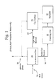
- FIG. 1 is a schematic diagram depicting an exemplary prior art process for removing vanadium from fuel containing vanadium (in contrast to the present invention which, as noted above, represents a significant departure from such processes).
- fuel source 10 is fed to a fractionation unit 20 comprising an adsorption material for extracting vanadium.
- the fuel is fractionated in fractionation unit 20 by separating the feed into a light fuel fraction 60 and a heavy fuel fraction 70.
- the light fuel fraction and gaseous phase are removed from the top of fractionation unit 20 and fed to a condenser (not shown).
- the light fuel fraction is condensed to a liquid and the gaseous phase, if present, remains in a vapor state.
- the condensate is then separated from the gaseous phase in separator 90.
- Gaseous phase 30, if any, may be combusted in a flare or fed to gas turbine 50 equipped with gas nozzles suitable for combusting hydrocarbon gases.
- the condensed light fuel fraction 60 forms as a liquid having a significantly reduced amount of vanadium and may be used to fuel a gas turbine 50.
- the heavy fuel fraction 70 typically has a high vanadium content and can be removed from the bottom of the fractionation unit 20 to be discarded or treated further for vanadium removal in a fuel partial oxidation or auto thermal cracking unit 80.
- the vanadium is oxidized in the fuel by partial oxidation or autothermal cracking to form a solid.
- FIG. 1 illustrates, the solid vanadium and ash from the fuel partial oxidation unit or autothermal cracking unit 80 are then separated from the treated fuel in separator 90.
- FIG. 2 is a schematic flow diagram depicting an exemplary embodiment of the steps taken according to the invention for forming and evaluating over time a sacrificial mitigation layer deposited on the thermal barrier coating of gas turbine engine components.
- the Ni-acetate solution is created as described above in solution forming step 100 and then applied in prescribed amounts to specific test coupons in Ni-acetate coating step 110.
- the amount of coating and application conditions may vary slightly for different coupons depending on the location and structure of the corresponding TBC components in the gas turbine engine.
- test coupons are heat treated to form NiO after being allowed to penetrate into the TBC as described above.
- the precise heat treatment and coating parameters for different coupons may vary slightly, depending on the exact location within the gas turbine engine in which they reside. Nominally, the coupons are coated and heat treated multiple times in order to ensure the structural integrity and uniform thickness of the final coating before being subjected to industrial gas turbine operating conditions.
- the coated coupons are exposed to the gas turbine exhaust at specific locations at step 170 with the installation taking place in a manner that allows the coupons to be physically removed and analyzed after fixed periods of time without shutting down the gas turbine engine.
- the coupons can be removed as shown in step 130 in order to determine the exact amount and composition of the remaining NiO layer. If, as indicated at step 140, the NiO layer has retained sufficient thickness and the NiO matrix has not deteriorated during the period of evaluation (see decision line 150), the coupon is returned to the same location inside the engine and the test continued as indicated at coating test feedback line 180.
- the test is discontinued at "Yes" line 160, indicating a possible shutdown of the engine for periodic maintenance.
- the time period between such maintenance shutdowns should be extended using the NiO coatings according to the invention.
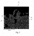
- FIG. 3 of the drawings is a scanning electron microscope (“SEM") photograph depicting the top surface of an exemplary gas turbine engine component having a single thermal barrier coating and a protective NiO coating applied thereon in accordance with the invention.
- a small cross section of the coated engine component is shown generally at 200 having thermal barrier coating 201 (such as an yttria-stabilized zirconia) applied to the top surface thereof.
- FIG. 3 also shows the presence of microscopic cracks 202 and 203 in the TBC, some of which extend up to the top surface of the coating, thereby making the TBC vulnerable to a reaction between vanadium pentoxide and the yttria-stabilized compounds in the TBC, i.e., by reacting with vanadium present in the gas turbine exhaust stream that forms nickel-vanadate.
- the NiO layer 204 in FIG. 3 forms a "sacrificial mitigation layer" that protects the underlying TBC from the unwanted vanadate reaction.
- NiO layer 204 is formed by initially applying a saturated liquid solution of nickel-acetate tetrahydrate in an amount sufficient to form a substantially uniform NiO layer over the TBC at room temperature and capable of penetrating into microscopic cracks 202 and 203.
- the relative thicknesses of the TBC and NiO layers can be seen by comparison to the 200 ⁇ m scale shown at the bottom left of FIG. 3 . Additional NiO layers can be deposited as described above, depending on the specific engine component involved and desired final NiO thickness.
Landscapes
- Chemical & Material Sciences (AREA)
- Engineering & Computer Science (AREA)
- Ceramic Engineering (AREA)
- Inorganic Chemistry (AREA)
- Physics & Mathematics (AREA)
- Thermal Sciences (AREA)
- General Chemical & Material Sciences (AREA)
- Chemical Kinetics & Catalysis (AREA)
- Materials Engineering (AREA)
- Mechanical Engineering (AREA)
- Metallurgy (AREA)
- Organic Chemistry (AREA)
- Turbine Rotor Nozzle Sealing (AREA)
- Other Surface Treatments For Metallic Materials (AREA)
Abstract
Description
- The present invention relates to a new process for forming an in situ layer of protective material over a thermal barrier coating ("TBC") used to protect the working components of a gas turbine engine and, in particular, to a new method for applying a sacrificial layer of material onto the TBC which effectively prevents the reaction of vanadium pentoxide with yttria-stabilized compounds in the TBC.
- Most gas turbine engines operate using compressed air that is burned with hydrocarbon fuel to produce hot exhaust gases which expand across a turbine to produce power. Turbine components, particularly turbine blades, often comprise nickel-based superalloys which provide excellent resistance to creep, metal fatigue and corrosion, i.e., the principle degradation mechanisms in the hot sections of the gas turbine engine, particularly the combustion chamber and turbine. Significant advances in high-temperature applications have been made in recent years, including by General Electric, using different nickel- and cobalt-based superalloys to form the key components of gas turbine engines, particularly the combustor and augmentor sections of the engines.
- Even the latest generation superalloys, however, are susceptible to damage by oxidation and hot corrosion which tend to accelerate the corrosion of the underlying metal substrate. For that reason, many engine components include some form of a thermal barrier coating. Because the number and severity of TBC applications have increased in the past decade, the premature spallation failure of TBCs during service is still a problem because a failure can often expose the bare metal to dangerously hot gases and remains a serious operational concern.
- The mechanisms by which TBCs fail are also varied and complex, the most important being thermal-expansion stresses, metal oxidation and physical changes in the TBC composition and properties. Ceramic materials, particularly yttria-stabilized zirconia (YSZ), are now widely used as a thermal barrier coating in TBC systems for gas turbine engines. Typically, the TBC used in the highest-temperature regions of the engines is deposited by electron beam physical vapor deposition (EBPVD) techniques that produce a grain structure capable of expanding and contracting without causing damaging stresses that lead to spallation.
- In addition, in order to promote adhesion and extend the service life of a TBC system, an oxidation-resistant bond coat is often employed, usually in the form of MCrAlX (where M is iron, cobalt and/or nickel, and X is yttrium or another rare earth element) or a diffusion aluminide coating. During exposure to high temperatures, such as during engine service, the bond coat oxidizes to form a tightly adherent alumina layer (e.g., aluminum oxide or Al2O3) that protects the underlying structure from catastrophic oxidation and adheres the TBC to the bond coat. Normally, the service life of a TBC system is limited by spallation at or near the interfaces of the bond coat with the TBC.
- It is known that vanadium pentoxide destabilizes yttria-stabilized zirconia by reacting with the yttria. The reaction results in formation of yttrium vanadate and monoclinic zirconia according to the following reaction:
Y2O3(s) (in YSZ) + V2O5(1) → 2YVO4(s) +m-ZrO2(s)
- The monoclinic phase of zirconia as shown above (m-ZrO2) is undesirable because it undergoes volume changes when thermally cycled, such as during the normal operation of the gas turbine engine. Such repeated cycling can lead to coating spallation and ultimately a potential catastrophic failure of critical engine components. It has been found that the problem of spallation may be accelerated by contaminants in the fuel being used to drive the gas turbine engine. That is, the hot corrosion is promoted by contaminants present in the hydrocarbon fuel and air mixture, particularly Middle East fuels containing even small amounts of vanadium. Vanadium is often found in residual fuel oils, as well as in some crude oils, typically in the form of a porphyrin or other organometallic complex. Inorganic compounds containing vanadium have also have been found in lower grade fuels.
- During combustion of the fuel, the vanadium reacts with oxygen to form various oxides, including VO, V2O3, V2O4(VO2) and V2O5. VO, V2O3 and V2O4(VO2) are considered refractory materials that have melting points above 1500°C, and thus normally will pass through the gas turbine as part of the exhaust stream. Vanadium pentoxide, V2O5, however, has a much lower melting point (in the range of about 650°C-670°C). Thus, V2O5 is normally a liquid at typical gas turbine operating temperatures and tends to deposit on the surfaces of hot components ultimately causing hot corrosion and contributing to spallation.
- In the past, various additives have been used as part of the combustor fuel in an effort to inhibit vanadium hot corrosion. For example, magnesium-containing compounds (e.g., MgSO4) have been used because they decompose to magnesium oxide (MgO), which in turn reacts with V2O5 to form magnesium vanadate (Mg3(VO4)2). Unfortunately, various residual sulfur compounds, such as from sodium sulfates and SO2 from the combustor fuel, tend to reduce the effectiveness of the MgO which preferentially reacts with the sulfur to form MgSO4, rather than with V2O5 to form magnesium vanadate. It has been found that magnesium-based compounds added to low-grade fuels, while helping to reduce the corrosive effect of vanadium, can result in the accumulation of ash-like deposits on interior gas turbine parts, which requires periodic shutdown and maintenance of the gas turbine engine to remove the accumulated deposits.
- Thus, notwithstanding various efforts in the past to control the adverse effects of vanadium pentoxide, the combustion of hydrocarbon fuels in gas turbine engines, particularly heavier fuels such as crude oils found in the Middle East which often contain vanadium, remains a serious problem, namely the accumulation of vanadium ash on the metallic surfaces of the hot gas path. Typically, the accumulated ash includes both V2O5 (vanadium pentoxide) and Na2SO4 (sodium sulfate). The ash material, which then forms a variety of sodium salts, causes fouling and corrosion of the hot gas path components due to the formation of low melting point reactive compounds containing vanadium. Eventually, as noted above, the fouling and corrosion over long periods of operation cause the metallic components to deteriorate or even fail, resulting in a need to shut down the entire gas turbine engine.
- The figures and accompanying text below describe a new method for providing a protective coating on gas turbine engine components comprising the steps of forming a saturated solution of nickel acetate tetrahydrate, applying a uniform thickness of the coating onto the thermal barrier coating of selected components of the gas turbine engine, and heat treating the coated component in air at a temperature sufficient to form an integral protective layer of NiO over the thermal barrier coating. Nominally, the saturated solution of nickel-acetate tetrahydrate is applied as a liquid in an amount sufficient to form a uniform NiO layer over the thermal barrier coating with sufficient solubility at room temperature to penetrate into the microscopic cracks of the thermal barrier coating.
- The NiO layer thus forms a "sacrificial mitigation layer" that substantially inhibits the reaction between vanadium pentoxide and yttria-stabilized compounds present in the thermal barrier coating by reacting with vanadium present in the exhaust stream of the gas turbine engine to form solid nickel-vanadate. Thus, in exemplary embodiments described herein, the nickel acetate tetrahydrate solution is applied in an amount sufficient to completely fill and seal all microscopic surface cracks in the thermal barrier coating, followed by a heat treatment carried out in an air furnace at a temperature of between 950°F and 1050°F.
- The present invention also includes gas turbine engine components treated in the manner described herein, i.e., components having a protective coating applied thereon which comprise a superalloy substrate, a thermal barrier coating applied to the superalloy substrate and a sacrificial NiO coating applied to the top of the thermal barrier coating. The invention also contemplates a new method for evaluating the effectiveness and expected life of a protective coating applied to the thermal barrier coating of gas turbine engine components which includes the steps of applying a uniform layer of nickel acetate tetrahydrate solution to test coupons having the same superalloy substrate and thermal barrier coating structure as selected components of the gas turbine engine, heat treating the coated test coupons in air at a temperature sufficient to form a protective layer of NiO having a defined thickness, inserting the test coupons into the gas turbine engine at locations corresponding to the target components, and determining the amount of NiO coating remaining on the test coupons after a defined period of time of operation of the gas turbine engine.
-
-
FIG. 1 is a schematic flow diagram showing an exemplary prior art process for treating the hot gas path of a conventional gas turbine engine in order to extract vanadium compounds present in the fuel for purposes of protecting selected TBC components from vanadium corrosion; -
FIG. 2 is a schematic flow diagram depicting an exemplary embodiment of the steps taken according to the invention for forming and evaluating over time a sacrificial mitigation layer deposited on the thermal barrier coating of selected gas turbine engine components; and -
FIG. 3 is a scanning electron microscope (SEM) photograph, depicting the cross section of the top surface of an exemplary gas turbine engine component having a thermal barrier coating and a NiO coating applied thereon in accordance with invention. - The present invention provides a different approach to resolving the problems inherent in using hydrocarbon fuel components in gas turbine engines that contain vanadium compounds (and thereby tend to generate vanadium pentoxide). In particular, the invention does not rely on any pre-treatment of the hydrocarbon fuel or the addition of NiO into the hydrocarbon fuel or the hot gas stream. Instead, a sacrificial mitigation layer of material is deposited directly on the thermal barrier coating of selected gas turbine engine components, namely those that form the hot gas path. The sacrificial mitigation layer effectively prevents or at least substantially inhibits the reaction over time between any vanadium pentoxide and yttria-stabilized compounds present in the TBC. Significantly, the protective layer can be formed from a saturated solution of Ni-acetate and then deposited (in effect "painted") directly onto the TBC surface. The entire coated components then undergo a prescribed thermal heat treatment to from a sacrificial NiO layer on the TBC. The coating and heat treatment steps may also be repeated as discussed below, depending on the specific end use application.
- The direct application coating method according to one aspect of the invention has been found superior in many respects to systems that introduce nickel or magnesium into the hot gas stream (or the base hydrocarbon fuel) in that the sacrificial mitigation layer tends to prolong gas turbine service life by inhibiting vanadium pentoxide from reacting with the yttria stabilized zirconia. The nickel oxide sacrificial layer on top of the TBC thus prevents adverse reactions from accruing to any significant extent until virtually all of the NiO layer has been depleted.
- The use of a layer of sacrificial mitigation layer also increases the anticipated life of hot gas path components that might otherwise suffer from spallation or a destabilized TBC. As a result, from a commercial standpoint, the gas turbine engine does not need to be inspected as often, nor does the engine need to be taken out of service in order to correct an ash accumulation problem. Such increases in the projected operating time offer significant commercial advantages where the units do not need to undergo maintenance during peak critical use periods.
- Nickel oxide on its own as a coating components is a relatively poor structural material. Nevertheless, nickel oxide has been found to be a valuable top coating for the TBC because it reacts with vanadium to form solid nickel-vanadate and will remain a solid at the anticipated elevated operating temperatures of most gas turbine engines. Vanadium, on the other hand, reacts with various materials to form a liquid at nominal gas turbine operating temperatures. It also reacts with MgO and NiO to produce solids. However, it has been found that nickel oxide outperforms magnesium as a potential TBC coating due to the likely interaction of the magnesium with sulfate, a compound often found in the gas turbine exhaust.
- Thus, even though NiO is considered a relatively poor structural material from the standpoint of strength, it has been found to be an ideal candidate as a protective layer on top of the TBC coating. The NiO coating applied to the TBC and treated in accordance with the invention penetrates into and seals the small surface porosity and cracks in the coating. In that manner, the final nickel oxide layer prevents vanadium pentoxide from penetrating into the TBC and reacting with the yttria. Because the vanadium pentoxide tends to penetrate the TBC layer across the entire cross-section of the coating, the invention effectively prevents the undesirable reactions from progressing across the same entire cross sectional area.
- An exemplary process for applying the nickel acetate tetrahydrate solution and related method of infiltration may be summarized as follows. A saturated solution of nickel acetate tetrahydrate is applied to the TBC in an amount sufficient to form a relatively uniform NiO particulate layer. The NiO-coated component then undergoes heat treatment of the NiO-coated component in air. Preferably, the saturated solution will be applied in the form of a matrix that remains a liquid and thus maintains its solubility long enough to thoroughly penetrate into the microscopic cracks of the TBC. The saturated solution is "painted" onto the thermal barrier coating to thereby infiltrate and completely fill and seal all TBC surface cracks. Normally, the entire exposed part will be coated after a thermal barrier coating heat treatment has been completed, i.e., after the TBC part has cooled to room temperature.
- It has been found that the Ni-acetate tetrahydrate coated TBC component should be heat treated in an air furnace to a temperature of between 950°F - 1050°F in order to expand the cracks and dry and convert the Ni precipitate to NiO. The engine component is held at the same temperature for a minimum of an hour and then furnace-cooled to below 800°F before removing the component from the furnace. The same nickel acetate tetrahydrate infiltration process can be repeated a second time by painting the part with a fresh saturated solution to again infiltrate and fill all remaining surface cracks. A similar heat treatment is then undertaken as described above. The infiltration process and heat treatment can be repeated a third time, if necessary, to ensure a uniform coating with uniform structural integrity.
- The following example illustrates the basic process steps and conditions used to form an in situ layer of protective material according to the invention.
-
FIG. 1 is a schematic diagram depicting an exemplary prior art process for removing vanadium from fuel containing vanadium (in contrast to the present invention which, as noted above, represents a significant departure from such processes). InFIG. 1 ,fuel source 10 is fed to afractionation unit 20 comprising an adsorption material for extracting vanadium. The fuel is fractionated infractionation unit 20 by separating the feed into alight fuel fraction 60 and aheavy fuel fraction 70. The light fuel fraction and gaseous phase are removed from the top offractionation unit 20 and fed to a condenser (not shown). The light fuel fraction is condensed to a liquid and the gaseous phase, if present, remains in a vapor state. The condensate is then separated from the gaseous phase inseparator 90. Gaseous phase 30, if any, may be combusted in a flare or fed togas turbine 50 equipped with gas nozzles suitable for combusting hydrocarbon gases. - Notably, the condensed
light fuel fraction 60 forms as a liquid having a significantly reduced amount of vanadium and may be used to fuel agas turbine 50. Theheavy fuel fraction 70 typically has a high vanadium content and can be removed from the bottom of thefractionation unit 20 to be discarded or treated further for vanadium removal in a fuel partial oxidation or auto thermal crackingunit 80. Normally, the vanadium is oxidized in the fuel by partial oxidation or autothermal cracking to form a solid. AsFIG. 1 illustrates, the solid vanadium and ash from the fuel partial oxidation unit orautothermal cracking unit 80 are then separated from the treated fuel inseparator 90. -
FIG. 2 is a schematic flow diagram depicting an exemplary embodiment of the steps taken according to the invention for forming and evaluating over time a sacrificial mitigation layer deposited on the thermal barrier coating of gas turbine engine components. The Ni-acetate solution is created as described above insolution forming step 100 and then applied in prescribed amounts to specific test coupons in Ni-acetate coating step 110. The amount of coating and application conditions may vary slightly for different coupons depending on the location and structure of the corresponding TBC components in the gas turbine engine. - In
step 120, the test coupons are heat treated to form NiO after being allowed to penetrate into the TBC as described above. Again, the precise heat treatment and coating parameters for different coupons may vary slightly, depending on the exact location within the gas turbine engine in which they reside. Nominally, the coupons are coated and heat treated multiple times in order to ensure the structural integrity and uniform thickness of the final coating before being subjected to industrial gas turbine operating conditions. - Once treated, the coated coupons are exposed to the gas turbine exhaust at specific locations at
step 170 with the installation taking place in a manner that allows the coupons to be physically removed and analyzed after fixed periods of time without shutting down the gas turbine engine. After a prescribed period of operation, the coupons can be removed as shown instep 130 in order to determine the exact amount and composition of the remaining NiO layer. If, as indicated atstep 140, the NiO layer has retained sufficient thickness and the NiO matrix has not deteriorated during the period of evaluation (see decision line 150), the coupon is returned to the same location inside the engine and the test continued as indicated at coatingtest feedback line 180. If, on the other hand, the coupon reflects a thickness decrease that endangers the underlying TBC, the test is discontinued at "Yes"line 160, indicating a possible shutdown of the engine for periodic maintenance. As noted above, the time period between such maintenance shutdowns should be extended using the NiO coatings according to the invention. -
FIG. 3 of the drawings is a scanning electron microscope ("SEM") photograph depicting the top surface of an exemplary gas turbine engine component having a single thermal barrier coating and a protective NiO coating applied thereon in accordance with the invention. A small cross section of the coated engine component is shown generally at 200 having thermal barrier coating 201 (such as an yttria-stabilized zirconia) applied to the top surface thereof. -
FIG. 3 also shows the presence ofmicroscopic cracks NiO layer 204 inFIG. 3 forms a "sacrificial mitigation layer" that protects the underlying TBC from the unwanted vanadate reaction. As noted above,NiO layer 204 is formed by initially applying a saturated liquid solution of nickel-acetate tetrahydrate in an amount sufficient to form a substantially uniform NiO layer over the TBC at room temperature and capable of penetrating intomicroscopic cracks FIG. 3 . Additional NiO layers can be deposited as described above, depending on the specific engine component involved and desired final NiO thickness. - While at least one embodiment of the invention has been described in connection with what is presently considered to be the most practical and preferred embodiment, it is to be understood that the invention is not to be limited to the disclosed embodiment, but on the contrary, is intended to cover various modifications and equivalent arrangements included within the scope of the appended claims.
Claims (19)
a superalloy substrate;
a thermal barrier coating applied to said superalloy substrate; and
a sacrificial NiO coating applied to the top of said thermal barrier coating.
applying a uniform layer of nickel acetate tetrahydrate solution to test coupons comprising the same superalloy substrate and thermal barrier coating structure as selected components of said gas turbine engine;
heat treating said coated test coupons in air at a temperature sufficient to form a protective layer of NiO having a defined thickness over said thermal barrier coating;
inserting said test coupons into said gas turbine engine at locations corresponding to said selected components;
determining the amount of NiO coating remaining on said test coupons after a defined period of time of operation of said gas turbine engine;
comparing said NiO coating thickness to specific NiO target values assigned to said selected components; and
removing said test coupons and shutting down said gas turbine engine when one or more of said NiO thickness levels fall below said NiO target values.
Applications Claiming Priority (1)
| Application Number | Priority Date | Filing Date | Title |
|---|---|---|---|
| US13/229,961 US20130065076A1 (en) | 2011-09-12 | 2011-09-12 | Nickel oxide mitigation layer for vanadium on thermal barrier coatings |
Publications (2)
| Publication Number | Publication Date |
|---|---|
| EP2573207A2 true EP2573207A2 (en) | 2013-03-27 |
| EP2573207A3 EP2573207A3 (en) | 2013-12-11 |
Family
ID=46963448
Family Applications (1)
| Application Number | Title | Priority Date | Filing Date |
|---|---|---|---|
| EP12183113.5A Withdrawn EP2573207A3 (en) | 2011-09-12 | 2012-09-05 | Nickel oxide mitigation layer for vandium on thermal barrier coatings |
Country Status (4)
| Country | Link |
|---|---|
| US (1) | US20130065076A1 (en) |
| EP (1) | EP2573207A3 (en) |
| JP (1) | JP2013060661A (en) |
| CN (1) | CN102994984A (en) |
Families Citing this family (4)
| Publication number | Priority date | Publication date | Assignee | Title |
|---|---|---|---|---|
| US9970305B2 (en) * | 2015-09-18 | 2018-05-15 | General Electric Company | Treatment process, oxide-forming treatment composition, and treated component |
| CN106917094A (en) * | 2015-12-24 | 2017-07-04 | 通用电气公司 | Protection product enable its can anti-sulphates corrosive method and the product with improved Sulfate corrosion resistance |
| JP6607837B2 (en) | 2016-10-06 | 2019-11-20 | 三菱重工業株式会社 | Thermal barrier coating film, turbine member and thermal barrier coating method |
| JP7169077B2 (en) | 2018-03-26 | 2022-11-10 | 三菱重工業株式会社 | Thermal barrier coating, turbine component, gas turbine, and method for producing thermal barrier coating |
Family Cites Families (2)
| Publication number | Priority date | Publication date | Assignee | Title |
|---|---|---|---|---|
| CA920037A (en) * | 1969-04-28 | 1973-01-30 | Nippon Steel Corporation | Method of making surface-treated steel plates high in the anticorrosiveness |
| US4639399A (en) * | 1985-11-26 | 1987-01-27 | The United States Of America As Represented By The Secretary Of The Navy | Nickel oxide, ceramic insulated, high temperature coating |
-
2011
- 2011-09-12 US US13/229,961 patent/US20130065076A1/en not_active Abandoned
-
2012
- 2012-09-05 EP EP12183113.5A patent/EP2573207A3/en not_active Withdrawn
- 2012-09-11 JP JP2012199091A patent/JP2013060661A/en active Pending
- 2012-09-12 CN CN201210335780.6A patent/CN102994984A/en active Pending
Non-Patent Citations (1)
| Title |
|---|
| None |
Also Published As
| Publication number | Publication date |
|---|---|
| US20130065076A1 (en) | 2013-03-14 |
| EP2573207A3 (en) | 2013-12-11 |
| JP2013060661A (en) | 2013-04-04 |
| CN102994984A (en) | 2013-03-27 |
Similar Documents
| Publication | Publication Date | Title |
|---|---|---|
| US9023486B2 (en) | Thermal barrier coating systems and processes therefor | |
| CA2709930C (en) | Thermal barrier coating systems including a rare earth aluminate layer for improved resistance to cmas infiltration and coated articles | |
| JP5802838B2 (en) | Thermal barrier coating system and method therefor | |
| US7862901B2 (en) | Yttria containing thermal barrier coating topcoat layer and method for applying the coating layer | |
| JP5160194B2 (en) | Ceramic corrosion resistant coating for oxidation resistance | |
| US20090169752A1 (en) | Method for Improving Resistance to CMAS Infiltration | |
| US7807231B2 (en) | Process for forming thermal barrier coating resistant to infiltration | |
| US20100028711A1 (en) | Thermal barrier coatings and methods of producing same | |
| EP2573207A2 (en) | Nickel oxide mitigation layer for vandium on thermal barrier coatings | |
| US8337996B2 (en) | Vanadium resistant coating system | |
| Marple et al. | Corrosion of thermal barrier coatings by vanadium and sulfur compounds | |
| US20100247755A1 (en) | Method of manufacturing or repairing a coating on a metallic substrate | |
| US20140094356A1 (en) | Treatment process, oxide-forming treatment composition, and treated component | |
| EP3144408B1 (en) | Treatment process, treatment composition | |
| Bernstein et al. | Corrosion of Industrial Gas Turbines | |
| US20130323518A1 (en) | Coating process, coating, and coated component | |
| US10514170B2 (en) | Treatment process, rejuvenation process, treatment composition, and treated component | |
| Meetham et al. | Coatings for High Temperature Materials |
Legal Events
| Date | Code | Title | Description |
|---|---|---|---|
| PUAI | Public reference made under article 153(3) epc to a published international application that has entered the european phase |
Free format text: ORIGINAL CODE: 0009012 |
|
| AK | Designated contracting states |
Kind code of ref document: A2 Designated state(s): AL AT BE BG CH CY CZ DE DK EE ES FI FR GB GR HR HU IE IS IT LI LT LU LV MC MK MT NL NO PL PT RO RS SE SI SK SM TR |
|
| AX | Request for extension of the european patent |
Extension state: BA ME |
|
| PUAL | Search report despatched |
Free format text: ORIGINAL CODE: 0009013 |
|
| AK | Designated contracting states |
Kind code of ref document: A3 Designated state(s): AL AT BE BG CH CY CZ DE DK EE ES FI FR GB GR HR HU IE IS IT LI LT LU LV MC MK MT NL NO PL PT RO RS SE SI SK SM TR |
|
| AX | Request for extension of the european patent |
Extension state: BA ME |
|
| RIC1 | Information provided on ipc code assigned before grant |
Ipc: C23C 18/12 20060101AFI20131105BHEP |
|
| STAA | Information on the status of an ep patent application or granted ep patent |
Free format text: STATUS: THE APPLICATION IS DEEMED TO BE WITHDRAWN |
|
| 18D | Application deemed to be withdrawn |
Effective date: 20140612 |