EP2573003A1 - Container - Google Patents
Container Download PDFInfo
- Publication number
- EP2573003A1 EP2573003A1 EP11783495A EP11783495A EP2573003A1 EP 2573003 A1 EP2573003 A1 EP 2573003A1 EP 11783495 A EP11783495 A EP 11783495A EP 11783495 A EP11783495 A EP 11783495A EP 2573003 A1 EP2573003 A1 EP 2573003A1
- Authority
- EP
- European Patent Office
- Prior art keywords
- storage
- container
- storage surface
- horizontal plane
- flange
- Prior art date
- Legal status (The legal status is an assumption and is not a legal conclusion. Google has not performed a legal analysis and makes no representation as to the accuracy of the status listed.)
- Withdrawn
Links
- 230000005484 gravity Effects 0.000 claims abstract description 14
- 238000003860 storage Methods 0.000 claims description 379
- 230000002093 peripheral effect Effects 0.000 claims description 7
- 238000004519 manufacturing process Methods 0.000 abstract description 39
- 238000002347 injection Methods 0.000 description 75
- 239000007924 injection Substances 0.000 description 75
- 238000007789 sealing Methods 0.000 description 53
- 238000000034 method Methods 0.000 description 30
- 238000003825 pressing Methods 0.000 description 25
- 230000000903 blocking effect Effects 0.000 description 23
- 238000005520 cutting process Methods 0.000 description 19
- 238000010438 heat treatment Methods 0.000 description 17
- 238000010276 construction Methods 0.000 description 9
- 239000000463 material Substances 0.000 description 7
- 238000003466 welding Methods 0.000 description 7
- 238000001816 cooling Methods 0.000 description 4
- 230000004927 fusion Effects 0.000 description 3
- 239000004677 Nylon Substances 0.000 description 2
- 239000004698 Polyethylene Substances 0.000 description 2
- 238000012217 deletion Methods 0.000 description 2
- 230000037430 deletion Effects 0.000 description 2
- 230000000694 effects Effects 0.000 description 2
- 229920001778 nylon Polymers 0.000 description 2
- -1 polyethylene Polymers 0.000 description 2
- 229920000573 polyethylene Polymers 0.000 description 2
- 239000000853 adhesive Substances 0.000 description 1
- 230000001070 adhesive effect Effects 0.000 description 1
- 230000004888 barrier function Effects 0.000 description 1
- 238000004140 cleaning Methods 0.000 description 1
- 230000007423 decrease Effects 0.000 description 1
- 230000005674 electromagnetic induction Effects 0.000 description 1
- 230000006698 induction Effects 0.000 description 1
- 239000002184 metal Substances 0.000 description 1
- 239000007769 metal material Substances 0.000 description 1
- 230000004048 modification Effects 0.000 description 1
- 238000012986 modification Methods 0.000 description 1
- 238000000465 moulding Methods 0.000 description 1
- 230000010355 oscillation Effects 0.000 description 1
- 239000004033 plastic Substances 0.000 description 1
- 229920003023 plastic Polymers 0.000 description 1
- 230000005855 radiation Effects 0.000 description 1
- 239000012780 transparent material Substances 0.000 description 1
Images





Classifications
-
- B—PERFORMING OPERATIONS; TRANSPORTING
- B65—CONVEYING; PACKING; STORING; HANDLING THIN OR FILAMENTARY MATERIAL
- B65D—CONTAINERS FOR STORAGE OR TRANSPORT OF ARTICLES OR MATERIALS, e.g. BAGS, BARRELS, BOTTLES, BOXES, CANS, CARTONS, CRATES, DRUMS, JARS, TANKS, HOPPERS, FORWARDING CONTAINERS; ACCESSORIES, CLOSURES, OR FITTINGS THEREFOR; PACKAGING ELEMENTS; PACKAGES
- B65D90/00—Component parts, details or accessories for large containers
- B65D90/12—Supports
-
- B—PERFORMING OPERATIONS; TRANSPORTING
- B65—CONVEYING; PACKING; STORING; HANDLING THIN OR FILAMENTARY MATERIAL
- B65D—CONTAINERS FOR STORAGE OR TRANSPORT OF ARTICLES OR MATERIALS, e.g. BAGS, BARRELS, BOTTLES, BOXES, CANS, CARTONS, CRATES, DRUMS, JARS, TANKS, HOPPERS, FORWARDING CONTAINERS; ACCESSORIES, CLOSURES, OR FITTINGS THEREFOR; PACKAGING ELEMENTS; PACKAGES
- B65D75/00—Packages comprising articles or materials partially or wholly enclosed in strips, sheets, blanks, tubes or webs of flexible sheet material, e.g. in folded wrappers
- B65D75/28—Articles or materials wholly enclosed in composite wrappers, i.e. wrappers formed by associating or interconnecting two or more sheets or blanks
- B65D75/30—Articles or materials enclosed between two opposed sheets or blanks having their margins united, e.g. by pressure-sensitive adhesive, crimping, heat-sealing, or welding
- B65D75/32—Articles or materials enclosed between two opposed sheets or blanks having their margins united, e.g. by pressure-sensitive adhesive, crimping, heat-sealing, or welding one or both sheets or blanks being recessed to accommodate contents
- B65D75/321—Both sheets being recessed
- B65D75/322—Both sheets being recessed and forming one compartment
-
- B—PERFORMING OPERATIONS; TRANSPORTING
- B65—CONVEYING; PACKING; STORING; HANDLING THIN OR FILAMENTARY MATERIAL
- B65D—CONTAINERS FOR STORAGE OR TRANSPORT OF ARTICLES OR MATERIALS, e.g. BAGS, BARRELS, BOTTLES, BOXES, CANS, CARTONS, CRATES, DRUMS, JARS, TANKS, HOPPERS, FORWARDING CONTAINERS; ACCESSORIES, CLOSURES, OR FITTINGS THEREFOR; PACKAGING ELEMENTS; PACKAGES
- B65D7/00—Containers having bodies formed by interconnecting or uniting two or more rigid, or substantially rigid, components made wholly or mainly of metal
- B65D7/02—Containers having bodies formed by interconnecting or uniting two or more rigid, or substantially rigid, components made wholly or mainly of metal characterised by shape
- B65D7/04—Containers having bodies formed by interconnecting or uniting two or more rigid, or substantially rigid, components made wholly or mainly of metal characterised by shape of curved cross-section, e.g. cans of circular or elliptical cross-section
-
- B—PERFORMING OPERATIONS; TRANSPORTING
- B65—CONVEYING; PACKING; STORING; HANDLING THIN OR FILAMENTARY MATERIAL
- B65D—CONTAINERS FOR STORAGE OR TRANSPORT OF ARTICLES OR MATERIALS, e.g. BAGS, BARRELS, BOTTLES, BOXES, CANS, CARTONS, CRATES, DRUMS, JARS, TANKS, HOPPERS, FORWARDING CONTAINERS; ACCESSORIES, CLOSURES, OR FITTINGS THEREFOR; PACKAGING ELEMENTS; PACKAGES
- B65D81/00—Containers, packaging elements, or packages, for contents presenting particular transport or storage problems, or adapted to be used for non-packaging purposes after removal of contents
- B65D81/18—Containers, packaging elements, or packages, for contents presenting particular transport or storage problems, or adapted to be used for non-packaging purposes after removal of contents providing specific environment for contents, e.g. temperature above or below ambient
- B65D81/20—Containers, packaging elements, or packages, for contents presenting particular transport or storage problems, or adapted to be used for non-packaging purposes after removal of contents providing specific environment for contents, e.g. temperature above or below ambient under vacuum or superatmospheric pressure, or in a special atmosphere, e.g. of inert gas
- B65D81/2046—Containers, packaging elements, or packages, for contents presenting particular transport or storage problems, or adapted to be used for non-packaging purposes after removal of contents providing specific environment for contents, e.g. temperature above or below ambient under vacuum or superatmospheric pressure, or in a special atmosphere, e.g. of inert gas under superatmospheric pressure
- B65D81/2053—Containers, packaging elements, or packages, for contents presenting particular transport or storage problems, or adapted to be used for non-packaging purposes after removal of contents providing specific environment for contents, e.g. temperature above or below ambient under vacuum or superatmospheric pressure, or in a special atmosphere, e.g. of inert gas under superatmospheric pressure in an least partially rigid container
-
- B—PERFORMING OPERATIONS; TRANSPORTING
- B65—CONVEYING; PACKING; STORING; HANDLING THIN OR FILAMENTARY MATERIAL
- B65D—CONTAINERS FOR STORAGE OR TRANSPORT OF ARTICLES OR MATERIALS, e.g. BAGS, BARRELS, BOTTLES, BOXES, CANS, CARTONS, CRATES, DRUMS, JARS, TANKS, HOPPERS, FORWARDING CONTAINERS; ACCESSORIES, CLOSURES, OR FITTINGS THEREFOR; PACKAGING ELEMENTS; PACKAGES
- B65D2207/00—Standing packages
Definitions
- This invention relates to a container for storing a storage article within a storage space.
- Japanese non-examined laid-open Patent Publication No. 2008-74478 discloses a container having two flexible barrel sheets and one bottom sheet.
- a bottom seal is formed by bonding a lower edge of the barrel sheet and a circumferential edge of the bottom sheet. Further, a side seal and a top seal are formed by bonding side edges and an upper edge of the barrel sheet.
- a storage article is stored in a storage space surrounded by the seals.
- the known container can freely stand on a horizontal plane by contact of the bottom-sealed edge with the horizontal plane when the edge is placed on the horizontal plane, but it is difficult to ensure large capacity of the storage space. It is, accordingly, an object of this invention to provide a rational technique for constructing a freestanding container.
- a representative embodiment of this invention is provided as a container formed by bonding a first storage member and a second storage member.
- the first and second storage members are preferably flexible.
- the first and second storage members for example, a sheet (film) formed of nylon and polyethylene and having a thickness of 50 to 200 ⁇ m is used.
- the materials and the thickness of the sheet are not limited to these.
- the first storage member has a first storage surface and a first flange extending from an edge of the first storage surface.
- the first storage surface has a bottom storage surface forming a bottom surface in a predetermined first direction on which the storage article is disposed.
- the first flange has a first lower flange extending along a second direction transverse to the first direction.
- the second storage member has a second storage surface and a second flange extending from an edge of the second storage surface.
- the second flange has a second lower flange extending along the second direction.
- the first and second storage members are bonded together at the edges of the first and second storage surfaces such that the first and second storage surfaces define the storage space.
- a line for projecting the center of gravity of the container perpendicularly to the horizontal plane passes through a region which is surrounded by a contact part between at least one of the first and second lower flanges and the horizontal plane and a contact part between the bottom storage surface and the horizontal plane, and the container freely stands on the horizontal plane.
- the storage article stored in the storage space is externally visible.
- at least one of the first and second storage members is formed by such a transparent material that the storage article stored in the storage space is externally visible.
- This transparency here refers to such transparency that at least the appearance of the storage article stored in the storage space can be checked.
- the container 10 of this embodiment is configured as a container which can freely stand on a horizontal plane with an article having a predetermined shape such as a cleaning article stored in a storage space. Naturally, an article having an appropriate shape can be stored in the storage space.
- the contour of the container 10, or the contours of a first storage member 20 and a second storage member 30 which form the container 10 can be appropriately changed according to an article to be stored.
- a first direction 70, a second direction 80 and a third direction 90 represent directions of the container 10 standing freely on the horizontal plane (standing on the horizontal plane without a support) when viewed from an upper storage surface 33 side (the left as viewed in FIG.
- the "first direction 70" represents a height direction (vertical direction as viewed in FIG. 2 ).
- the “one side in the first direction 70” and “the other side in the first direction 70” represent a lower side (lower side as viewed in FIG. 2 ) and an upper side (upper side as viewed in FIG. 2 ), respectively.
- the "second direction 80" represents a horizontal (transverse) direction (front-back direction as viewed in FIG. 2 ).
- the "one side in the second direction” and “the other side in the second direction” represent the right (front as viewed in FIG. 2 ) and the left (back as viewed in FIG. 2 ), respectively.
- the "third direction 90" represents a front-back direction (horizontal direction as viewed in FIG. 2 ).
- the "one side in the third direction” and “the other side in the third direction” represent the front (left as viewed in FIG. 2 ) and the back (right as viewed in FIG. 2 ), respectively.
- the "concave shape” and the “convex shape” are shapes as viewed from the storage space side and essentially refer to an outwardly bulged shape and an inwardly bulged shape, respectively.
- FIG. 1 is a perspective view of the container 10 and FIG. 2 is a view as viewed from a direction of arrow II in FIG. 1 .
- FIG. 3 is a perspective view showing lower and upper storage members 20, 30 which form the container 10.
- the container 10 of this embodiment is formed by bonding the lower and upper storage members 20,30 which are shown in FIG. 3 .
- a storage member which is placed on the lower side of the container 10 standing freely on the horizontal plane is referred to as the "lower storage member".
- the lower and upper storage members 20, 30 are formed by a sheet (film) which is flexible and has high airtightness (gas barrier property) and a moisture-proofing effect.
- this sheet (film) for example, a sheet formed of nylon and polyethylene and having a basis weight of 180 g/m 2 and a thickness of 50 to 200 ⁇ m is used. Naturally, the material, basis weight and thickness of the sheet are not limited to these.
- the lower and upper storage members 20, 30 may be formed by different sheets. Further, at least one of the lower and upper storage members 20, 30 is preferably so transparent that a storage article 400 stored in the storage space 10a is visible through the storage member, and it is formed, for example, of a transparent sheet. It is essential for such a sheet to be so transparent that at least the appearance of the storage article 400 stored in the storage space 10a can be checked.
- the lower storage member 20 has a concave lower storage surface 23 which defines a concave lower storage space 20a.
- the concave lower storage surface 23 has a bottom (on one side in the first direction 70) having a concave bottom storage surface 24 forming a concave bottom surface 24a.
- the lower storage surface 23 and the bottom storage surface 24 are shaped in a concave form having an opening on the other side (upper side) in the first direction 70.
- the storage article 400 is fixedly disposed on the concave bottom surface 24a.
- the construction in which the storage article 400 "is fixedly disposed” represents a construction in which the storage article 400 is fixed to the concave bottom surface 24a such that it can be prevented from moving within the storage space 10a during carriage of the container 10 and can be removed from the bottom surface 24a.
- the storage article 400 can be fixedly disposed on the bottom surface 24a by using appropriate methods. For example, the storage article 400 is removably mounted on a mat board and then the mat board is fixed on the bottom surface 24a by an adhesion tape or an adhesive.
- the bottom storage surface 24 is shaped such that the storage article 400 can be fixedly disposed on the concave bottom surface 24a, and the lower storage surface 23 is shaped such that the storage article can be stored in the storage space 10a.
- the lower storage member 20 has a flange 22 extending from an edge 21 of the lower storage surface 23.
- the edge 21 includes a lower edge 2 1 c on one side (lower side) in the first direction 70, an upper edge 21a on the other side (upper side) in the first direction 70, a right edge 21b on one side (right side) in the second direction 80 and a left edge 21d on the other side (left side) in the second direction 80.
- the flange 22 includes a lower flange 22c extending from the lower edge 21 c to the one side (lower side) in the first direction 70 (downward) and along the second direction 80, an upper flange 22a extending from the upper edge 21a to the other side (upper side) in the first direction 70 (upward) and along the second direction 80, a right flange 22b extending from the right edge 21b to the one side (right side) in the second direction 80 (rightward) and along the first direction 70, and a left flange 22d extending from the left edge 21d to the other side (left side) in the second direction 80 (leftward) and along the first direction 70.
- Each of the flanges 22a, 22b, 22c, 22d has an edge.
- the lower flange 22c has a lower edge 22c1 on the one side (lower side) in the first direction 70.
- the lower storage member 20, the lower storage surface 23, the bottom surface 24a, the bottom storage surface 24 are features that correspond to the "first storage member", the “first storage surface”, the “concave bottom surface”, the “bottom storage surface”, respectively, according to this invention.
- the edge 21 is a feature that corresponds to the "edge of the first storage surface (first edge)" according to this invention, and the edges 21a, 21b, 21c, 21d are features that correspond to the "first upper edge", the “first right edge", the "first lower edge” and the “first left edge”, respectively, according to this invention.
- the flange 22 is a feature that corresponds to the "first flange” according to this invention
- the flanges 22a, 22b, 22c, 22d are features that correspond to the "first upper flange", the “first right flange”, the “first lower flange” and the “first left flange”, respectively, according to this invention
- the lower edge 22c1of the lower flange 22c is a feature that corresponds to the "lower edge of the first lower flange” according to this invention.
- An upper storage member 30 has an upper storage surface 33.
- the upper storage surface 33 is shaped such the storage article can be stored in the storage space 10a.
- the upper storage surface 33 has a concave shape and defines a concave storage space 30a.
- the upper storage surface 33 is shaped in a concave form having an opening on the one side (lower side) in the first direction 70.
- the upper storage surface 33 may be shaped in a planar form.
- the upper storage member 30 has a flange 32 extending from an edge 31 of the upper storage surface 33.
- the edge 31 includes a lower edge 31c on the one side (lower side) in the first direction 70, an upper edge 31a on the other side (upper side) in the first direction 70, a right edge 31b on the one side (right side) in the second direction 80 and a left edge 31 d on the other side (left side) in the second direction 80.
- the flange 32 includes a lower flange 32c extending from the lower edge 31c to the one side (lower side) in the first direction 70 (downward) and along the second direction 80, an upper flange 32a extending from the upper edge 31a to the other side (upper side) in the first direction 70 (upward) and along the second direction 80, a right flange 32b extending from the right edge 31b to the one side (right side) in the second direction 80 (rightward) and along the first direction 70 and a left flange 32d extending from the left edge 31d to the other side (left side) in the second direction 80(leflward) and along the first direction 70.
- Each of the flanges 32a, 32b, 32c, 32d has an edge.
- the lower flange 32c has a lower edge 32c1 on the one side (lower side) in the first direction 70.
- the lower storage member 30 and the lower storage surface 33 are features that correspond to the "second storage member” and the “second storage surface”, respectively, according to this invention.
- the edge 31 is a feature that corresponds to the "edge of the second storage surface (second edge)" according to this invention, and the edges 31a, 31b, 31c, 31d are features that correspond to the "second upper edge", the “second right edge”, the "second lower edge” and the “second left edge”, respectively, according to this invention.
- the flange 32 is a feature that corresponds to the "second flange” according to this invention
- the flanges 32a, 32b, 32c, 32d are features that correspond to the "second upper flange", the “second right flange”, the “second lower flange” and the “second left flange”, respectively, according to this invention.
- the lower edge 32c1 of the lower flange 32c is a feature that corresponds to the "lower edge of the second lower flange” according to this invention.
- the edges of the flanges 22a to 22d of the lower storage member 20 and the edges of the flanges 32a to 32d of the upper storage member 30 are preferably opposed (aligned) with each other, but they may be displaced with respect to each other.
- the length (width) of the flanges 22a to 22d of the lower storage member 20 from the edges 21 b to 21 d and the length (width) of the flanges 32a to 32d of the upper storage member 30 from the edges 31b to 31 d are set, for example, to 5 to 10 mm.
- the container 10 of this embodiment is constructed to freely stand on a horizontal plane by contact of the lower flange 22c (32c) and the bottom storage surface 24 with the horizontal plane.
- the lower edge 22c (32c1) of the lower flange 22c (32c) and the bottom storage surface 24 get into contact with the horizontal plane.
- the lower flange 22c (32c) is configured to have sufficient strength for the container to freely stand.
- the lower flange 22c (32c) is formed of a sheet having desired strength.
- the lower flanges 22c, 32c are bonded together so as to provide the lower flange with desired strength.
- the lower and upper storage members 20, 30 are laid one on the other such that the lower storage surface 23 and the upper storage surface 33 (the edge 21 of the lower storage surface 23 and the edge 31 of the upper storage surface 33) are opposed to each other, and in this state, they are bonded together at a bonded part 11.
- the lower and upper storage members 20, 30 are bonded together at an upper bonded part 11 a provided in a region of the upper edge 21 a (31 a), a right bonded part 11b provided in a region of the right edge 21 b (31b), a lower bonded part 11c provided in a region of the lower edge 21 c (31c) and a left bonded part 11d provided in a region of the left edge 21 d (31 d).
- Each of the bonded parts 11a to lid has a width, for example, of about 3 mm.
- the container 10 has, for example, a length (height) of about 250 mm along the first direction 70, a length (width) of about 140 mm along the second direction 80 and a length (depth) of about 90 mm along the third direction 90.
- the container 10 can be easier to freely stand.
- the pressure in the storage space 10a is set in the range of 0.01 to 5 times atmospheric pressure, or suitably in the range of 1 to 5 times atmospheric pressure, or more suitably in the range of 1 to 3 times atmospheric pressure.
- the container 10 of this embodiment is configured to freely stand by contact of the lower flanges 22c, 32c and the lower storage surface 23 with a horizontal plane.
- the container 10 has the following construction. If a region surrounded by a contact part of the lower flanges 22c, 32c with a horizontal plane and a contact part of the lower storage surface 23 with the horizontal plane has a larger area, the container 10 can freely stand with greater stability and the storage article 400 can be easily disposed fixedly. Therefore, in this embodiment, the bottom storage surface 24 is formed such that the concave bottom surface 24a has a generally planar shape extending generally in parallel to the horizontal plane when the container 10 freely stands on the horizontal plane.
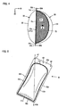
- the lower storage surface 23 having the bottom storage surface 24 is formed by deep drawing of the sheet. Further, the bottom storage surface 24 is formed to have a generally arcuate peripheral contour as viewed from the one side (or the other side) in the first direction 70. In this case, as shown in FIG. 4 , when the container 10 freely stands on the horizontal plane, the container 10 comes in contact with the horizontal plane at contact parts T1, T2.
- the contact part T1 is a contact part between the lower flanges 22c, 32c and the horizontal plane and provided along the lower edge 22c1 of the lower flange 22c and the lower edge 32c1 of the lower flange 32c.
- the contact part T2 is a contact part between the bottom storage surface 24 and the horizontal plane and provided along the peripheral contour of the bottom storage surface 24.
- the contact part T1 is provided along a straight line and the contact part T2 is provided along a circular arc.
- the positions of the contact parts T1, T2 are not limited to the positions shown in FIG. 4 .
- the lower flanges 22c, 32c may not become flat under heat or pressure caused when the lower and upper storage members 20, 30 are bonded together.
- the lower edge 22c1 of the lower flange 22c and the lower edge 32c1 of the lower flange 32c do not extend in a straight line, so that the contact part T1 is provided along not a straight line but a curved line.
- the peripheral contour of the bottom storage surface 24 is not limited to the arcuate contour.
- the contact part T2 between the bottom storage surface 24 and the horizontal plane is arranged along the peripheral contour of the bottom storage surface 24.
- the center of gravity G is positioned such that the container 10 is easy to freely stand.
- the position of the center of gravity G of the container 10 can be found, for example, by a method shown in FIGS. 5 and 6 .
- Holes 41, 42, 43 are formed at three points along the second direction 80 on the other (upper) end of the upper flange 22a (32a) of the container 10 in the first direction 70.
- the container 10 is supported at the hole 41 and dangled in a free state.
- a normal 41 G passing through the hole 41 is determined by viewing the container from the one side (the front) in the third direction 90.
- FIG. 5 the container 10 is supported at the hole 41 and dangled in a free state.
- a normal 41 G passing through the hole 41 is determined by viewing the container from the one side (the front) in the third direction 90.
- the container 10 is supported at the hole 42 and dangled in a free state. Then a normal 42G passing through the hole 42 is determined by viewing the container from the one side (the front) in the third direction 90. Thirdly, as shown in FIG. 7 , the container 10 is supported at the hole 43 and dangled in a free state. Then a normal 43G passing through the hole 43 is determined by viewing the container from the one side (the right) in the second direction 80. A point of intersection of the normals 41 G, 42G, 43G determined as described above is defined as the position of the center of gravity G of the container 10. Next, as shown in FIG.
- the container 10 is placed on the horizontal plane F such that the lower flange 22c (32c) and the bottom storage surface 24 are held in contact with the horizontal plane F. Then a line g for projecting the center of gravity G of the container 10 perpendicularly to the horizontal plane F is drawn. At this time, as shown in FIG. 4 , the line g passes through a region S which is surrounded by the contact part T1 between the lower flanges 22c, 32c and the horizontal plane F and the contact part T2 between the bottom storage surface 24 and the horizontal plane F.
- the region S refers to a region having the largest area in a region surrounded by a line connecting the contact part T1 between the lower flanges 22c, 32c and the horizontal plane F with the contact part T2 between the bottom storage surface 24 and the horizontal plane F. Further, preferably, the line g passes through the center of the region S.
- the flanges 22, 32 In the container 10 of this embodiment which is constructed to freely stand on the horizontal plane F by contact of the lower flanges 22c, 32c and the bottom storage surface 24 with the horizontal plane F, it is essential for the flanges 22, 32 to have at least the lower flanges 22c, 32c.
- the container 10 of this embodiment is constructed such that the right and left bonded parts 11b, 11d or the right and left flanges 22b (32b), 22d (32d) are inclined when viewed from the one side (or the other side) in the second direction 80.
- the right flange 22b (32b) and the left flange 22d (32d) are inclined such that their upper ends on the other side (upper side) in the first direction 70 are located to the other side in the third direction 90 (rearward) or to the lower storage surface 23 side with respect to their lower ends on the one side (lower side) in the first direction 70.
- the right and left bonded parts 11b, 11d or the right and left flanges 22b (32b), 22d (32d) form an angle 0 ( ⁇ 90°) with respect to the third direction (front-back direction) parallel to the horizontal plane when viewed from the one side (the right) in the second direction 80.
- the angle 0 is set in the range of 75 to 80°.
- the container 10 is allowed to freely stand on the horizontal plane F by placing the lower edge 22c1 of the lower flange 22c, the lower edge 32c1 of the lower flange 32c and the bottom storage surface 24 in contact with the horizontal plane F, but other methods may also be used to allow the container 10 to freely stand on the horizontal plane F.
- it may be constructed to freely stand by placing at least one of the lower edge 22c1 of the lower flange 22c and the lower edge 32c1 of the lower flange 32c and the bottom storage surface 24 in contact with the horizontal plane F.
- it may be constructed to freely stand by placing at least one of a region of the lower flange 22c other than the lower edge 22c1 and a region of the lower flange 32c other than the lower edge 32c1 and the bottom storage surface 24 in contact with the horizontal plane F. Further, the lower edge 22c1 of the lower flange 22c and the lower edge 32c1 of the lower flange 32c may come in contact with the horizontal plane F at the same positions (regions opposed to each other) or at different positions.
- FIGS. 8 and 9 A container 110 of another embodiment is shown in FIGS. 8 and 9 .
- FIG. 8 is a perspective view of the container 110 of another embodiment
- FIG. 9 is a sectional view taken along line IX-IX in FIG. 8 .
- the container 110 of this embodiment includes a lower storage member 120 and an upper storage member 130.
- the lower storage member 120 has a different structure from the lower storage member 20 of the container 10. Therefore, in the following description, the structure of the lower storage member 120 is mainly explained.
- the lower storage member 120 has a lower storage surface 123 defining a lower storage space 120a
- the lower storage surface 123 has concave bottom storage surfaces 124, 125 and a convex bottom storage surface 126 which form a convex bottom surface on one side (lower side) in the first direction 70.
- the concave bottom storage surface 124, the concave bottom storage surface 125 and the convex bottom storage surface 126 form a concave bottom surface 124a, a concave bottom surface 125a and a convex bottom surface 126a, respectively.
- the concave bottom storage surfaces 124,125 are formed along a peripheral contour of the convex bottom storage surface 126.
- the storage article 400 is fixedly mounted on the convex bottom surface 126a
- the "concave shape” and the “convex shape” refer to a shape having a concave on the storage space 110a side and a shape having a convex on the storage space 110a side, respectively.
- the convex bottom storage surface 126 is shaped such that the storage article 400 can be fixedly disposed on the convex bottom surface 126a.
- the convex bottom storage surface 126 is configured such that the convex bottom surface 126a has a generally planar shape extending generally in parallel to the horizontal plane when the container 110 freely stands on the horizontal plane.
- the container 110 of this embodiment is constructed to freely stand by contact of the concave bottom storage surfaces 124, 125 of the lower storage member 120 with a horizontal plane. Specifically, it is constructed such that, when the concave bottom storage surfaces 124,125 are in contact with the horizontal plane, a line g for projecting the center of gravity G of the container 110 perpendicularly to the horizontal plane passes through a region S which is surrounded by a contact part T1 between the concave bottom storage surface 124 and the horizontal plane and a contact part T2 between the concave bottom storage surface 125 and the horizontal plane.
- the region S refers to a region having the largest area in a region surrounded by a line connecting the contact part T1 between the concave bottom storage surface 124 and the horizontal plane and the contact part T2 between the concave bottom storage surface 125 and the horizontal plane.
- the container 110 of this embodiment is constructed such that right and left bonded parts or right and left flanges 122b (132b), 122d (132d) are inclined when viewed from the one side in the second direction 80. Further, the construction in which the right flange 122b (132b) and the left flange 122d (132d) are inclined may be omitted.
- the concave bottom storage surfaces 124, 125 are appropriately shaped and positioned such that the storage article 400 can be fixedly disposed on the convex bottom surface 126a and the container 110 can freely stand on the horizontal plane.
- the concave bottom storage surface 124 is formed generally in parallel to the second direction 80 (to the lower flange) and the concave bottom storage surface 125 is formed along a generally circular arc extending from both ends of the concave bottom storage surface 124.
- the concave bottom storage surfaces 124, 125 are contiguously formed with each other.
- the contact part T1 between the concave bottom storage surface 124 and the horizontal plane is provided along a straight line (including a generally straight line) and the contact part T2 between the concave bottom storage surface 125 and the horizontal plane is provided along a circular arc (including a generally circular arc).
- the concave bottom storage surfaces 124, 125 only have to be designed to come in contact with the horizontal plane at least partially along the straight line and the circular arc. For example, as shown in FIG.
- the concave bottom storage surface 124 comes in contact with the horizontal plane at a contact part T11 formed along part of the straight line and the concave bottom storage surface 125 comes in contact with the horizontal plane at contact parts T21, T22 formed along part of the circular arc.
- the concave bottom storage surface 24 of the container 10 and the concave bottom storage surfaces 124, 125 and the convex bottom storage surface 126 of the container 110 are formed by deep drawing, the sheet thickness of the deep-drawn parts is reduced, so that the strength may be reduced. Therefore, in order to increase the strength, a rubber or other similar materials may be provided in the deep-drawn parts. Further, the deep-drawn parts having a curved shape are easier to slide. Therefore, in order to prevent such sliding, a rubber or other similar materials may be provided in the deep-drawn parts. In order to facilitate removal of the storage article 400 from the storage space, an opening aid may be provided.
- a notch or a part (non-bonded part) which can be easily peeled off may be formed in the container.
- the container can freely stand on the horizontal plane not only when the storage article 400 is fixedly disposed on the concave bottom surface 24a of the container 10 (or on the convex bottom surface 126a of the container 110), but also when the storage article 400 is not stored in the storage space.
- a line for projecting the center of gravity of the container 10 (110) perpendicularly to the horizontal plane passes through a region surrounded by the contact parts when the storage article 400 is not stored in the storage space and at least one of the lower flanges 22c and 32c and the bottom storage surface 24 of the container 10 (or the concave bottom storage surfaces 124, 125 of the container 110) are placed on the horizontal plane.
- the container of this invention is formed of a flexible sheet in its entirety, so that it is soft and easy to handle. Further, the container can be reduced in size at the time of disposal, so that it can be easily disposed of and its disposal cost can be reduced.
- the container has the bottom storage surface on which the storage article is fixedly disposed, so that its storage capacity can be increased. Further, by pressurizing the storage space, the storage article can be protected from damage by external force applied to the upper and lower storage surfaces. Further, even if the upper and lower storage surfaces are dented by external force, they can be restored to their original state.
- FIG. 11 One embodiment of a container manufacturing method according to this invention is schematically shown in FIG. 11 .
- the container manufacturing method shown in FIG. 11 is suitable for manufacturing the container in which the pressure in the storage space 10a is set to be equal to or higher than the atmospheric pressure.
- Step P1 is a lower storage surface forming step.
- a lower storage surface of a lower storage member is formed in a first sheet.
- the lower storage surface of the container of this embodiment has a concave bottom storage surface which forms a concave bottom surface (or a concave bottom storage surface and a convex bottom storage surface which form a convex bottom surface).
- step P1 the lower storage surface having the concave bottom storage surface (or having the concave bottom storage surface and the convex bottom storage surface) is formed by deep drawing. Naturally, various other methods can also be used to form the lower storage surface.
- Step P1 is a feature that corresponds to the "first storage surface forming step” according to this invention.
- Step P2 is an air injection hole forming step. In step P2, an air injection hole is formed in the first sheet as an opening for air injection to inject air into the storage space.
- Step P2 is a feature that corresponds to the "gas injection hole forming step” according to this invention.
- Step P3 is a storage article supplying step. In step P3, a storage article is supplied into a lower storage space defined by the lower storage surface of the first sheet.
- Step P3 is a feature that corresponds to the "storage article supplying step” according to this invention.
- Step P4 is an upper storage surface forming step. In step P4, an upper storage surface of an upper storage member is formed in a second sheet. Various other methods can also be used to form the upper storage surface according to the shape of the upper storage surface.
- Step P4 is a feature that corresponds to the "second storage surface forming step” according to this invention.
- Step P5 is a sheet overlaying step. In step P5, the first sheet having the lower storage surface and the second sheet having the upper storage surface are overlaid one on the other.
- Step P5 is a feature that corresponds to the "sheet overlaying step" according to this invention.
- the air injection hole for injecting air is formed in the first sheet, but it may be formed in the second sheet.
- step P2 is bypassed and an air injection hole forming step of forming the air injection hole in the second sheet is provided between step P4 and step P5.
- Step P6 is a primary sealing step.
- the first and second sheets are bonded (primarily sealed) together at a region other than an air passage.
- the first and second sheets are bonded such that a storage space is formed by the lower and upper storage spaces and the air passage for injecting air into the storage space is formed between the air injection hole formed in the first sheet (or the second sheet) and the storage space.
- the first and second sheets are suitably bonded together at the edges of the lower and upper storage spaces. Naturally, they may be bonded together at regions other than the edges of the lower and upper storage spaces.
- the primary sealing step in order to form the bonded part, typically, parts of the first and second sheets are heated to the softening point of the sheet material or higher and melted, and the melted parts are pressed and fusion bonded, and then the fusion-bonded part is cooled.
- the primary sealing step consists of a heating step, a pressing step and a cooling step.
- Step P6 is a feature that corresponds to the "primary sealing step" according to this invention.
- Step P7 is an air injecting step. In step P7, air is injected into the storage space through the air injection hole via the air passage.
- an air injection nozzle is inserted into the air injection hole and air is injected into the storage space through the air injection nozzle via the air passage and an air inlet.
- the pressure in the storage space is set to be equal to or higher than the atmospheric pressure or, for example, in the range of 1 to 5 times atmospheric pressure, or suitably in the range of 1 to 3 times atmospheric pressure.
- the air, the air injection hole and step P7 are features that correspond to the "gas", the "gas injection hole” and the "gas injecting step", respectively, according to this invention.
- Step P8 is an air passage blocking step. In step P8, the air passage is temporarily blocked in order to prevent a subsequent secondary sealing from being performed in pressurized atmosphere.
- the air passage is suitably blocked at a position toward the storage space or, for example, in the vicinity of the air inlet of the storage space.
- the air passage can be temporarily blocked suitably by pressing at least one of the first and second sheets toward each other.
- a pair of pressing members can be used which are opposed to each other and can be controlled to be placed in a standby position or a working position. When the pressing members are controlled to be placed in the working position, the first and second sheets are pressed toward each other, so that the air passage is blocked.
- Various other methods can also be used to block the air passage.
- Step P8 is a feature that corresponds to the "gas passage blocking step" according to this invention. Further, in this specification, “blocking the gas passage” means “temporarily closing the gas passage at an arbitrary point so as to prevent gas from passing through this point".
- Step P9 is a secondary sealing step.
- the first and second sheets are bonded together at a region of the air passage.
- Step P9 is suitably performed when the region of the air passage toward the storage space is blocked and air injection from the air injection hole is stopped (for example, the air injection nozzle is removed from the air injection hole).
- the secondary sealing is performed in its entirety or in part of a region between the blocked point of the air passage and the air injection hole.
- the secondary sealing step typically includes a heating step, a pressing step and a cooling step.
- Step P9 is a feature that corresponds to the "secondary sealing step" according to this invention.
- the secondary sealing step is not performed in pressurized atmosphere, so that the bonding strength can be ensured.
- Step P10 is an air passage unblocking step.
- the air passage is unblocked.
- the pressing member is controlled to be held in the standby position.
- pressure upon the at least one of the first and second sheets is released and the air passage is unblocked.
- Step P10 is a feature that corresponds to the "gas passage unblocking step" according to this invention.
- Step P11 is a cutting step.
- the first and second sheets which are subjected to the primary and secondary sealing steps are cut off at cutting positions corresponding to the shape and the size of the container. For example, the first and second sheets are cut lengthwise along the longitudinal direction of the first and second sheets and cut widthwise along a direction transverse to the longitudinal direction.
- Step P11 is a feature that corresponds to the "cutting step" according to this invention.
- the container manufacturing method of this invention is not limited to that shown in FIG. 11 .
- a method of performing each of the steps shown in FIG. 11 and the sequence of performing each of the steps can be appropriately changed.
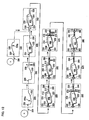
- FIG. 12 One embodiment of the container manufacturing device of this invention is schematically shown in FIG. 12 .
- the container manufacturing device shown in FIG. 12 is suitable for manufacturing the container in which the pressure in the storage space 10a is set to be equal to or higher than the atmospheric pressure.
- the container manufacturing device shown in FIG. 12 includes a lower storage surface forming section 500, an air injection hole forming section 510, a storage article supplying section 520, an upper storage surface forming section 530, a sheet overlaying section 540, a primary sealing section 550, an air injecting section 560, an air passage blocking section (air passage unblocking section) 570, a secondary sealing section 580 and a cutting section 590.
- a lower storage surface 223 having a bottom storage surface is formed in a first sheet 220.
- the lower storage surface 223 is formed by deep drawing.
- the lower storage surface forming section 500 can be configured as a device for forming the lower storage surface 223 by using a known method.
- the lower storage surface 223 defines a lower storage space 220a.
- the lower storage surface forming section 500 is a feature that corresponds to the "first storage surface forming section (first storage surface forming step)" according to this invention.
- an air injection opening in the form of an air injection hole 228 for injecting air into a storage space is formed in the first sheet 220.
- the air injection hole 228 is formed between adjacent lower storage surfaces 223.
- the air injection hole 228 is formed in the first sheet 220 by using a hole punch 240.
- Various other devices can also be used to form the air injection hole 228 in the first sheet 220.
- the shape of the air injection hole 228 is appropriately selected.
- the air injection hole 228 is shaped to allow the air injecting nozzle to be inserted.
- the air, the air injection hole 228 and the air injection hole forming section 510 are features that correspond to the "gas", the “gas injection opening” and the “gas injection hole forming section (gas injection hole forming step) ", respectively, according to this invention.
- the storage article supplying section 520 the storage article 400 is supplied into the lower storage space 220a defined by the lower storage surface 223 of the first sheet 220. Further, the storage article 400 is fixedly disposed on the concave bottom formed by the bottom storage surface of the lower storage surface 223 such that it can be prevented from moving within the storage space during carriage.
- the storage article supplying section 520 is a feature that corresponds to the "storage article supplying section" according to this invention.
- the upper storage surface 233 is formed in the second sheet 230.
- the upper storage surface forming section 530 can be configured as a device for forming the upper storage surface 233 by using a known method.
- the upper storage surface forming section 530 is a feature that corresponds to the "second storage surface forming section (second storage surface forming step)" according to this invention.
- the first and second sheets 220, 230 are overlaid one on the other. They are suitably overlaid such that the lower storage surface 223 of the first sheet 220 and the upper storage surface 233 of the second sheet 230 (edges of the lower and upper storage surfaces 223, 233) are opposed to each other.
- the sheet overlaying section 540 is a feature that corresponds to the "sheet overlaying section (sheet overlaying step)" according to this invention. Further, the air injection hole 228 can also be formed in the second sheet 230. When the air injection hole 228 is formed in the second sheet 230, the air injection hole forming section 510 is provided between the upper storage surface forming section 520 and the sheet overlaying section 540.
- the first and second sheets 220, 230 overlaid one on the other are bonded together (primarily sealed) such that the storage space is defined by the lower and upper storage surfaces 223, 233 and the air passage 213 is formed between the air injection hole 228 and the storage space (an air inlet 212 of the storage space).
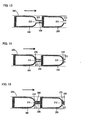
- a bonded part 250 (first bonded part) at which the first and second sheets 220, 230 are bonded together is formed in a region of the edges of the lower and upper storage surfaces 223, 233 other than the air passage 213 between the air injection hole 228 and the air inlet 212 of the storage space (see FIG. 13 ).
- the primary sealing section 550 is a feature that corresponds to the "primary sealing section (primary sealing step)" according to this invention.
- the primary sealing section 550 includes, for example, a heating section that heats the first and second sheets 220, 230 to melt sheet materials, a pressing section that applies pressure on (presses) the melted part to fusion bond them, and a cooling section that cools the fusion-bonded part to form the bonded part.
- heating section various types of heating sections can be used, including a heating section of a type that heats with heat generated from a heating wire to which low voltage and large current are supplied in a short time (impulse welding method), a heating section of a type that heats with radiant heat from a highly-heated hot plate (noncontact-type hot plate welding method), a heating section of a type that heats by contact of a highly-heated hot plate (contact-type hot plate welding method), a heating section of a type that heats with friction heat generated by pressing and rotating a circular molding at high speed (spin welder welding method), a heating section of a type that heats with heat generated by molecular motion of plastic which is caused by high-frequency polarity change (high-frequency induction welding method), a heating section of a type that fusion-bonds portions to be bonded by radiation of high frequencies, where the portions of the sheets to be bonded are shaped to be mated with each other and a metal material (such as a wire) is a heating
- the air injecting section 560 air is injected into the storage space.
- a nozzle (air injection nozzle) 260 is inserted into the air injection hole 228, and then air is injected from the nozzle 260 into the storage space via the air passage 213 and the air inlet 212.
- the pressure in the storage space is set, for example, in the range of 1 to 5 times atmospheric pressure, or suitably in the range of 1 to 3 times atmospheric pressure.
- the air injecting section 560 is a feature that corresponds to the "gas injecting section (gas injecting step)" according to this invention.
- the air passage blocking section 570 after air is injected into the storage space, the air passage is temporarily blocked.
- the air passage 213 is blocked at a position toward the storage space (the air inlet 212).
- the air passage blocking section 570 has a pair of pressing members 270 opposed to each other.
- the pair pressing members 270 can be controlled to be placed in the working position in which the first and second sheets 220, 230 are pressed toward each other, or in the standby position in which the first and second sheets 220, 230 are not pressed.
- the opposed pair pressing members 270 are moved to the working position and bring the first and second sheets 220, 230 into contact with each other in the region of the air passage 213 toward the storage space (in the vicinity of the air inlet 212 of the storage space) (see FIG. 14 ).
- the pressing members 270 and the air passage blocking section 570 are features that correspond to the "pressing member” and the “gas passage blocking section (gas passage blocking step)", respectively, according to this invention. Further, in order to bring the first and second sheets 220, 230 into contact with each other, at least one of the first and second sheets 220, 230 only has to be pressed toward the other. Therefore, it is essential for the air passage blocking section 570 to have a pressing member which presses at least one of the first and second sheets 220, 230 toward the other.
- the first and second sheets 220, 230 are bonded together (secondarily sealed) such that the air passage 213 blocked by the pressing members 270 is closed.
- a bonded part 280 (second bonded part) is formed between a part of the air passage 213 which is blocked by the pressing members 270 and the air injection hole 228, and bonds the first and second sheets 220, 230 (see FIG. 15 ). It is essential for the bonded part 280 to be formed such that the air injection hole 228 and the storage space (the air inlet 213) do not communicate with each other when pressing of the pressing members 270 is released, and the bonded part 280 may be formed in part of the region between the blocked part and the air injection hole 228.
- the secondary sealing section 580 can be formed by a heating section that heats the first and second sheets 220, 230 to melt sheet materials, a pressing section that applies pressure on (presses) the melted parts to fusion bond them, and a cooling section that cools the fusion-bonded part to form the bonded part.
- a heating section that heats the first and second sheets 220, 230 to melt sheet materials
- a pressing section that applies pressure on (presses) the melted parts to fusion bond them
- a cooling section that cools the fusion-bonded part to form the bonded part.
- the secondary sealing section 580 is a feature that corresponds to the "secondary sealing section (secondary sealing step)" according to this invention.
- the air passage blocking section 570 after secondary sealing by the secondary sealing section 580, the air passage is unblocked.
- the pair pressing members 270 are controlled to be placed in the standby position in which the first and second sheets 220, 230 are not pressed.
- the air passage blocking section 570 is a feature that corresponds to the "air passage unblocking section (air passage unblocking step)" according to this invention.
- the first and second sheets 220, 230 subjected to the primary sealing and the secondary sealing are cut (for example, cut lengthwise along the longitudinal direction and cut widthwise along a direction transverse to the longitudinal direction) by a cutting member (cutter) 290, so that the container 10 is obtained (see FIG. 16 ).
- the cutting section 590 is a feature that corresponds to the "cutting section (cutting step)" according to this invention.
- the air injection hole 228 is formed in the first sheet 220 or the second sheet 230 as the air injection opening, but the method for forming the air injection opening (gas injection opening) is not limited to this.
- a container manufacturing device container manufacturing method
- an opening defined by edges of the first and second sheets is used as the air injection opening.
- the air injection hole forming step P2 shown in FIG. 11 and the air injection hole forming section 510 shown in FIG. 12 can be omitted. As shown in FIG.
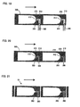
- FIG. 17 shows a section (step) corresponding to the "primary sealing section (primary sealing step) 550" shown in FIG. 12 .
- FIG. 17 shows a section (step) corresponding to the "primary sealing section (primary sealing step) 550" shown in FIG. 12 .
- FIG. 18 shows a section (step) corresponding to the "air injection section (air injection step) 560" shown in FIG. 12 .
- FIG. 19 shows a section (step) corresponding to the "air passage blocking section (air passage blocking step) 570" shown in FIG. 12 .
- a bonded part (secondary sealing) 380 is formed to bond the first and second sheets 320, 330 together such that the air passage 313 is closed.
- FIG. 20 shows a section (step) corresponding to the "secondary sealing section (secondary sealing step) 580" shown in FIG. 12 .
- FIG. 21 shows a section (step) corresponding to the "cutting section (cutting step) 590" shown in FIG. 12 .
- the air injection hole forming step air injection hole forming section
- the air injecting step air injecting section
- the air passage blocking step air passage blocking section
- the secondary sealing step secondary sealing section
- the container, the container manufacturing method and the container manufacturing device of this invention are not limited to those described in the above embodiments, but rather, may be added to, changed, replaced with alternatives or otherwise modified.
- the storage article to be stored in the container can be appropriately selected.
- the shape of the container (for example, the shapes of the bottom storage surface, the lower storage surface and the upper storage surface) is designed such that the container is easy to freely stand (can stand on the horizontal plane without a support). Further, the shape of the container can be appropriately changed according to the shape of the storage article.
- the pressure in the storage space is set within a range in which the container can freely stand, and preferably in the range in which the storage article can be protected against damage by external force applied to the upper and lower storage surfaces.
- the pressure in the storage space is set, for example, in the range of 0.01 to 5 times atmospheric pressure, or suitably in the range of 1 to 3 times atmospheric pressure.
- Each of the features or constructions of the container explained in the embodiments can be used separately or in combination of appropriately selected ones.
- air is injected into the storage space of one container through one air injection opening (gas injection opening), but air can be injected into storage spaces of a plurality of containers through one air injection opening (gas injection opening).
- it can be constructed such that adjacent containers are arranged with the storage spaces in opposite orientations along the feeding direction of the sheets (first and second sheets) and air is injected into the storage spaces of two containers adjacent along the feeding direction of the sheets through one air injection opening (gas injection opening) at the same time.
- it can be constructed such that air is injected into the storage spaces of two containers adjacent in a direction transverse to the feeding direction of the sheets through one air injection opening (gas injection opening) at the same time.
- Gas to be injected into the storage space is not limited to air.
- the container manufacturing method and the container manufacturing device explained in the embodiments can be appropriately changed. For example, as for the steps of the container manufacturing method, change of sequence, addition, deletion, combination and division can be appropriately made.
- a known container manufacturing method and a known container manufacturing device may be used in place of the container manufacturing method and the container manufacturing device described in the above embodiments. For example, they can be used to manufacture the container in which the pressure in the storage space is set to be equal to or lower than the atmospheric pressure.
Landscapes
- Engineering & Computer Science (AREA)
- Mechanical Engineering (AREA)
- Chemical & Material Sciences (AREA)
- Composite Materials (AREA)
- Packages (AREA)
Abstract
Provided is a technology to manufacture a large capacity self-standing container at a low cost. A container (10) comprises a lower container member (20) and an upper container member (30) joined at joint portions (11a to 11d). The container (10) has a content space (10a) formed by a lower container face (23) and an upper container face (33), and lower flanges (22c and 32c). The lower container face (23) has a concave bottom container face (24) at the bottom, which forms a concave bottom face (24a) wherein an object to be contained (400) is fixed. The container is structured so that when at least one of the lower flanges (22c and 32c) and the bottom container face (24) are arranged on a horizontal plane, a line perpendicularly projected to the horizontal surface from the gravity center of the container (10) passes an area framed by a contact portion between the at least one of the lower flanges (22c and 32c) and the horizontal surface and a contact portion between the bottom container face (24) and the horizontal surface.
Description
- This invention relates to a container for storing a storage article within a storage space.
- Japanese non-examined laid-open Patent Publication No.
2008-74478 - The known container can freely stand on a horizontal plane by contact of the bottom-sealed edge with the horizontal plane when the edge is placed on the horizontal plane, but it is difficult to ensure large capacity of the storage space.
It is, accordingly, an object of this invention to provide a rational technique for constructing a freestanding container. - The above-described problem is solved by features as defined in claims of this invention. A representative embodiment of this invention is provided as a container formed by bonding a first storage member and a second storage member. The first and second storage members are preferably flexible.
- As the first and second storage members, for example, a sheet (film) formed of nylon and polyethylene and having a thickness of 50 to 200 µm is used. The materials and the thickness of the sheet are not limited to these. The first storage member has a first storage surface and a first flange extending from an edge of the first storage surface.
- The first storage surface has a bottom storage surface forming a bottom surface in a predetermined first direction on which the storage article is disposed.
- The first flange has a first lower flange extending along a second direction transverse to the first direction.
- The second storage member has a second storage surface and a second flange extending from an edge of the second storage surface.
- The second flange has a second lower flange extending along the second direction.
The first and second storage members are bonded together at the edges of the first and second storage surfaces such that the first and second storage surfaces define the storage space. - When at least one of the first and second lower flanges and the bottom storage surface are placed on a horizontal plane, a line for projecting the center of gravity of the container perpendicularly to the horizontal plane passes through a region which is surrounded by a contact part between at least one of the first and second lower flanges and the horizontal plane and a contact part between the bottom storage surface and the horizontal plane, and the container freely stands on the horizontal plane.
- Further, it is preferably constructed such that the storage article stored in the storage space is externally visible. For example, at least one of the first and second storage members is formed by such a transparent material that the storage article stored in the storage space is externally visible. This transparency here refers to such transparency that at least the appearance of the storage article stored in the storage space can be checked.
- According to this invention, a rational technique for constructing a freestanding container is provided.
Other objects, features and advantages of this invention will be readily understood after reading the following detailed description together with the accompanying drawings and the claims. -
-
FIG. 1 is a perspective view showing one embodiment of a container according to this invention. -
FIG. 2 is a view as viewed from a direction of arrow II inFIG.1 . -
FIG. 3 is a perspective view showing an upper storage member and a lower storage member which form the container of the one embodiment. -
FIG. 4 is a sectional view taken along line IV-IV inFIG. 1 . -
FIG. 5 schematically illustrates a method for obtaining the center of gravity. -
FIG. 6 schematically illustrates a method for obtaining the center of gravity. -
FIG. 7 schematically illustrates a method for obtaining the center of gravity. -
FIG. 8 is a perspective view showing another embodiment of the container according to this invention. -
FIG. 9 is a sectional view taken along line IX-IX inFIG. 8 . -
FIG. 10 is a view showing a modification of the second embodiment of the container according to this invention. -
FIG. 11 schematically shows one embodiment of a container manufacturing method according to this invention. -
FIG. 12 schematically shows one embodiment of a container manufacturing device according to this invention. -
FIG. 13 schematically shows a primary sealing section (primary sealing step) in the embodiment of the container manufacturing device. -
FIG. 14 schematically shows an air passage blocking section (air passage blocking step) in the embodiment of the container manufacturing device. -
FIG. 15 schematically shows a secondary sealing section (secondary sealing step) in the embodiment of the container manufacturing device. -
FIG. 16 schematically shows a cutting section (cutting step) in the embodiment of the container manufacturing device. -
FIG. 17 schematically shows a primary sealing section (primary sealing step) in another embodiment of the container manufacturing device. -
FIG. 18 schematically shows an air injecting section (air injecting step) in the second embodiment of the container manufacturing device. -
FIG.19 schematically shows an air passage blocking section (air passage blocking step) in the second embodiment of the container manufacturing device. -
FIG. 20 schematically shows a secondary sealing section (secondary sealing step) in the second embodiment of the container manufacturing device. -
FIG. 21 schematically shows a cutting section (cutting step) in the second embodiment of the container manufacturing device. - Each of the additional features and method steps disclosed above and below may be utilized separately or in conjunction with other features and method steps to provide and manufacture improved containers and methods for using such containers and devices utilized therein. Representative examples of the present invention, which examples utilized many of these additional features and method steps in conjunction, will now be described in detail with reference to the drawings. This detailed description is merely intended to teach a person skilled in the art further details for practicing preferred aspects of the present teachings and is not intended to limit the scope of the invention. Only the claims define the scope of the claimed invention. Therefore, combinations of features and steps disclosed within the following detailed description may not be necessary to practice the invention in the broadest sense, and are instead taught merely to particularly describe some representative examples of the invention, which detailed description will now be given with reference to the accompanying drawings.
Oneembodiment 10 of a container of this invention is now explained with reference toFIGS. 1 to 7 . Thecontainer 10 of this embodiment is configured as a container which can freely stand on a horizontal plane with an article having a predetermined shape such as a cleaning article stored in a storage space. Naturally, an article having an appropriate shape can be stored in the storage space. The contour of thecontainer 10, or the contours of afirst storage member 20 and asecond storage member 30 which form thecontainer 10 can be appropriately changed according to an article to be stored. Further, in the following explanation, afirst direction 70, asecond direction 80 and athird direction 90 represent directions of thecontainer 10 standing freely on the horizontal plane (standing on the horizontal plane without a support) when viewed from anupper storage surface 33 side (the left as viewed inFIG. 2 ). The "first direction 70" represents a height direction (vertical direction as viewed inFIG. 2 ). The "one side in thefirst direction 70" and "the other side in thefirst direction 70" represent a lower side (lower side as viewed inFIG. 2 ) and an upper side (upper side as viewed inFIG. 2 ), respectively. Further, the "second direction 80" represents a horizontal (transverse) direction (front-back direction as viewed inFIG. 2 ). The "one side in the second direction" and "the other side in the second direction" represent the right (front as viewed inFIG. 2 ) and the left (back as viewed inFIG. 2 ), respectively. Further, the "third direction 90" represents a front-back direction (horizontal direction as viewed inFIG. 2 ). The "one side in the third direction" and "the other side in the third direction" represent the front (left as viewed inFIG. 2 ) and the back (right as viewed inFIG. 2 ), respectively.
Further, in this embodiment, the "concave shape" and the "convex shape" are shapes as viewed from the storage space side and essentially refer to an outwardly bulged shape and an inwardly bulged shape, respectively. - The construction of the
container 10 according to this embodiment is described in brief with reference toFIGS. 1 to 3 .FIG. 1 is a perspective view of thecontainer 10 andFIG. 2 is a view as viewed from a direction of arrow II inFIG. 1 . Further,FIG. 3 is a perspective view showing lower andupper storage members container 10.
Thecontainer 10 of this embodiment is formed by bonding the lower andupper storage members FIG. 3 . Further, in this specification, a storage member which is placed on the lower side of thecontainer 10 standing freely on the horizontal plane is referred to as the "lower storage member". The lower andupper storage members upper storage members upper storage members storage article 400 stored in thestorage space 10a is visible through the storage member, and it is formed, for example, of a transparent sheet. It is essential for such a sheet to be so transparent that at least the appearance of thestorage article 400 stored in thestorage space 10a can be checked. - The
lower storage member 20 has a concavelower storage surface 23 which defines a concavelower storage space 20a. The concavelower storage surface 23 has a bottom (on one side in the first direction 70) having a concavebottom storage surface 24 forming aconcave bottom surface 24a. Specifically, thelower storage surface 23 and thebottom storage surface 24 are shaped in a concave form having an opening on the other side (upper side) in thefirst direction 70. Thestorage article 400 is fixedly disposed on theconcave bottom surface 24a. The construction in which thestorage article 400 "is fixedly disposed" represents a construction in which thestorage article 400 is fixed to theconcave bottom surface 24a such that it can be prevented from moving within thestorage space 10a during carriage of thecontainer 10 and can be removed from thebottom surface 24a. Thestorage article 400 can be fixedly disposed on thebottom surface 24a by using appropriate methods. For example, thestorage article 400 is removably mounted on a mat board and then the mat board is fixed on thebottom surface 24a by an adhesion tape or an adhesive. Thebottom storage surface 24 is shaped such that thestorage article 400 can be fixedly disposed on theconcave bottom surface 24a, and thelower storage surface 23 is shaped such that the storage article can be stored in thestorage space 10a.
Further, thelower storage member 20 has a flange 22 extending from an edge 21 of thelower storage surface 23. In this embodiment, the edge 21 includes a lower edge 2 1 c on one side (lower side) in thefirst direction 70, anupper edge 21a on the other side (upper side) in thefirst direction 70, aright edge 21b on one side (right side) in thesecond direction 80 and aleft edge 21d on the other side (left side) in thesecond direction 80. Further, the flange 22 includes alower flange 22c extending from thelower edge 21 c to the one side (lower side) in the first direction 70 (downward) and along thesecond direction 80, anupper flange 22a extending from theupper edge 21a to the other side (upper side) in the first direction 70 (upward) and along thesecond direction 80, aright flange 22b extending from theright edge 21b to the one side (right side) in the second direction 80 (rightward) and along thefirst direction 70, and aleft flange 22d extending from theleft edge 21d to the other side (left side) in the second direction 80 (leftward) and along thefirst direction 70. Each of theflanges lower flange 22c has a lower edge 22c1 on the one side (lower side) in thefirst direction 70.
Thelower storage member 20, thelower storage surface 23, thebottom surface 24a, thebottom storage surface 24 are features that correspond to the "first storage member", the "first storage surface", the "concave bottom surface", the "bottom storage surface", respectively, according to this invention. The edge 21 is a feature that corresponds to the "edge of the first storage surface (first edge)" according to this invention, and theedges flanges lower flange 22c is a feature that corresponds to the "lower edge of the first lower flange" according to this invention. - An
upper storage member 30 has anupper storage surface 33. Theupper storage surface 33 is shaped such the storage article can be stored in thestorage space 10a. In this embodiment, theupper storage surface 33 has a concave shape and defines aconcave storage space 30a. Specifically, theupper storage surface 33 is shaped in a concave form having an opening on the one side (lower side) in thefirst direction 70. Further, theupper storage surface 33 may be shaped in a planar form.
Further, theupper storage member 30 has a flange 32 extending from an edge 31 of theupper storage surface 33. In this embodiment, the edge 31 includes alower edge 31c on the one side (lower side) in thefirst direction 70, anupper edge 31a on the other side (upper side) in thefirst direction 70, aright edge 31b on the one side (right side) in thesecond direction 80 and aleft edge 31 d on the other side (left side) in thesecond direction 80. Further, the flange 32 includes alower flange 32c extending from thelower edge 31c to the one side (lower side) in the first direction 70 (downward) and along thesecond direction 80, anupper flange 32a extending from theupper edge 31a to the other side (upper side) in the first direction 70 (upward) and along thesecond direction 80, aright flange 32b extending from theright edge 31b to the one side (right side) in the second direction 80 (rightward) and along thefirst direction 70 and aleft flange 32d extending from theleft edge 31d to the other side (left side) in the second direction 80(leflward) and along thefirst direction 70. Each of theflanges lower flange 32c has a lower edge 32c1 on the one side (lower side) in thefirst direction 70.
Thelower storage member 30 and thelower storage surface 33 are features that correspond to the "second storage member" and the "second storage surface", respectively, according to this invention. The edge 31 is a feature that corresponds to the "edge of the second storage surface (second edge)" according to this invention, and theedges flanges lower flange 32c is a feature that corresponds to the "lower edge of the second lower flange" according to this invention. - Further, when the
lower storage member 20 and theupper storage member 30 are bonded together, the edges of theflanges 22a to 22d of thelower storage member 20 and the edges of theflanges 32a to 32d of theupper storage member 30 are preferably opposed (aligned) with each other, but they may be displaced with respect to each other. The length (width) of theflanges 22a to 22d of thelower storage member 20 from theedges 21 b to 21 d and the length (width) of theflanges 32a to 32d of theupper storage member 30 from theedges 31b to 31 d are set, for example, to 5 to 10 mm.
Further, thecontainer 10 of this embodiment is constructed to freely stand on a horizontal plane by contact of thelower flange 22c (32c) and thebottom storage surface 24 with the horizontal plane. Specifically, thelower edge 22c (32c1) of thelower flange 22c (32c) and thebottom storage surface 24 get into contact with the horizontal plane. For this purpose, thelower flange 22c (32c) is configured to have sufficient strength for the container to freely stand. For example, thelower flange 22c (32c) is formed of a sheet having desired strength. Alternatively, thelower flanges - As shown in
FIGS. 1 and2 , the lower andupper storage members lower storage surface 23 and the upper storage surface 33 (the edge 21 of thelower storage surface 23 and the edge 31 of the upper storage surface 33) are opposed to each other, and in this state, they are bonded together at a bonded part 11. In this embodiment, the lower andupper storage members part 11 a provided in a region of theupper edge 21 a (31 a), a right bondedpart 11b provided in a region of theright edge 21 b (31b), a lower bondedpart 11c provided in a region of thelower edge 21 c (31c) and a left bondedpart 11d provided in a region of theleft edge 21 d (31 d). Each of the bondedparts 11a to lid has a width, for example, of about 3 mm. Further, thecontainer 10 has, for example, a length (height) of about 250 mm along thefirst direction 70, a length (width) of about 140 mm along thesecond direction 80 and a length (depth) of about 90 mm along thethird direction 90. - Suitably, air is injected into the
storage space 10a If pressure in thestorage space 10a is lower, thecontainer 10 can be easier to freely stand. In order to protect thestorage article 400 from damage by external force applied to thelower storage surface 23 and theupper storage surface 33, however, it is better to increase pressure in thestorage space 10a so as to increase resilience of thelower storage surface 23 and theupper storage surface 33.
In this embodiment, the pressure in thestorage space 10a is set in the range of 0.01 to 5 times atmospheric pressure, or suitably in the range of 1 to 5 times atmospheric pressure, or more suitably in the range of 1 to 3 times atmospheric pressure. - The
container 10 of this embodiment is configured to freely stand by contact of thelower flanges lower storage surface 23 with a horizontal plane. For this purpose, thecontainer 10 has the following construction.
If a region surrounded by a contact part of thelower flanges lower storage surface 23 with the horizontal plane has a larger area, thecontainer 10 can freely stand with greater stability and thestorage article 400 can be easily disposed fixedly. Therefore, in this embodiment, thebottom storage surface 24 is formed such that theconcave bottom surface 24a has a generally planar shape extending generally in parallel to the horizontal plane when thecontainer 10 freely stands on the horizontal plane. Further, in this embodiment, thelower storage surface 23 having thebottom storage surface 24 is formed by deep drawing of the sheet.
Further, thebottom storage surface 24 is formed to have a generally arcuate peripheral contour as viewed from the one side (or the other side) in thefirst direction 70. In this case, as shown inFIG. 4 , when thecontainer 10 freely stands on the horizontal plane, thecontainer 10 comes in contact with the horizontal plane at contact parts T1, T2. The contact part T1 is a contact part between thelower flanges lower flange 22c and the lower edge 32c1 of thelower flange 32c. The contact part T2 is a contact part between thebottom storage surface 24 and the horizontal plane and provided along the peripheral contour of thebottom storage surface 24. InFIG. 4 , the contact part T1 is provided along a straight line and the contact part T2 is provided along a circular arc. Further, the positions of the contact parts T1, T2 are not limited to the positions shown inFIG. 4 . For example, thelower flanges upper storage members lower flange 22c and the lower edge 32c1 of thelower flange 32c do not extend in a straight line, so that the contact part T1 is provided along not a straight line but a curved line.
Further, the peripheral contour of thebottom storage surface 24 is not limited to the arcuate contour. The contact part T2 between thebottom storage surface 24 and the horizontal plane is arranged along the peripheral contour of thebottom storage surface 24. - Further, in the
container 10 of this embodiment, the center of gravity G is positioned such that thecontainer 10 is easy to freely stand.
The position of the center of gravity G of thecontainer 10 can be found, for example, by a method shown inFIGS. 5 and6 .Holes second direction 80 on the other (upper) end of theupper flange 22a (32a) of thecontainer 10 in thefirst direction 70. First, as shown inFIG. 5 , thecontainer 10 is supported at thehole 41 and dangled in a free state. Then a normal 41 G passing through thehole 41 is determined by viewing the container from the one side (the front) in thethird direction 90. Secondly, as shown inFIG. 6 , thecontainer 10 is supported at thehole 42 and dangled in a free state. Then a normal 42G passing through thehole 42 is determined by viewing the container from the one side (the front) in thethird direction 90. Thirdly, as shown inFIG. 7 , thecontainer 10 is supported at thehole 43 and dangled in a free state. Then a normal 43G passing through thehole 43 is determined by viewing the container from the one side (the right) in thesecond direction 80. A point of intersection of thenormals container 10.
Next, as shown inFIG. 2 , thecontainer 10 is placed on the horizontal plane F such that thelower flange 22c (32c) and thebottom storage surface 24 are held in contact with the horizontal plane F. Then a line g for projecting the center of gravity G of thecontainer 10 perpendicularly to the horizontal plane F is drawn. At this time, as shown inFIG. 4 , the line g passes through a region S which is surrounded by the contact part T1 between thelower flanges bottom storage surface 24 and the horizontal plane F. The region S refers to a region having the largest area in a region surrounded by a line connecting the contact part T1 between thelower flanges bottom storage surface 24 and the horizontal plane F. Further, preferably, the line g passes through the center of the region S. By provision of such a construction, thecontainer 10 becomes easier to freely stand with thelower flange 22c (32c) and thebottom storage surface 24 in contact with the horizontal plane.
In thecontainer 10 of this embodiment which is constructed to freely stand on the horizontal plane F by contact of thelower flanges bottom storage surface 24 with the horizontal plane F, it is essential for the flanges 22, 32 to have at least thelower flanges - Further, the
container 10 of this embodiment is constructed such that the right and left bondedparts flanges 22b (32b), 22d (32d) are inclined when viewed from the one side (or the other side) in thesecond direction 80.
As shown inFIG. 2 , theright flange 22b (32b) and theleft flange 22d (32d) are inclined such that their upper ends on the other side (upper side) in thefirst direction 70 are located to the other side in the third direction 90 (rearward) or to thelower storage surface 23 side with respect to their lower ends on the one side (lower side) in thefirst direction 70. In other words, when thelower flanges bottom storage surface 24 of thecontainer 10 come in contact with the horizontal plane F, the right and left bondedparts flanges 22b (32b), 22d (32d) form an angle 0 (< 90°) with respect to the third direction (front-back direction) parallel to the horizontal plane when viewed from the one side (the right) in thesecond direction 80. In this embodiment, the angle 0 is set in the range of 75 to 80°. By provision of the construction in which the right and left bondedparts flanges 22b (32b), 22d (32d) are inclined, thecontainer 10 is easier to freely stand.
Further, the construction in which theright flange 22b (32b) and theleft flange 22d (32d) are inclined may be omitted. - In the above description, the
container 10 is allowed to freely stand on the horizontal plane F by placing the lower edge 22c1 of thelower flange 22c, the lower edge 32c1 of thelower flange 32c and thebottom storage surface 24 in contact with the horizontal plane F, but other methods may also be used to allow thecontainer 10 to freely stand on the horizontal plane F. For example, it may be constructed to freely stand by placing at least one of the lower edge 22c1 of thelower flange 22c and the lower edge 32c1 of thelower flange 32c and thebottom storage surface 24 in contact with the horizontal plane F. Alternatively, it may be constructed to freely stand by placing at least one of a region of thelower flange 22c other than the lower edge 22c1 and a region of thelower flange 32c other than the lower edge 32c1 and thebottom storage surface 24 in contact with the horizontal plane F.
Further, the lower edge 22c1 of thelower flange 22c and the lower edge 32c1 of thelower flange 32c may come in contact with the horizontal plane F at the same positions (regions opposed to each other) or at different positions. - The
container 10 of the above-described embodiment freely stands on the horizontal plane by thelower flange 22c (32c) and the lower storage surface 23 (the bottom storage surface 24), but thecontainer 10 may be constructed to freely stand on the horizontal plane solely by the lower storage surface. Acontainer 110 of another embodiment is shown inFIGS. 8 and9 .FIG. 8 is a perspective view of thecontainer 110 of another embodiment andFIG. 9 is a sectional view taken along line IX-IX inFIG. 8 .
Like thecontainer 10, thecontainer 110 of this embodiment includes alower storage member 120 and anupper storage member 130. In thecontainer 110 of this embodiment, thelower storage member 120 has a different structure from thelower storage member 20 of thecontainer 10. Therefore, in the following description, the structure of thelower storage member 120 is mainly explained.
Thelower storage member 120 has alower storage surface 123 defining alower storage space 120a Thelower storage surface 123 has concave bottom storage surfaces 124, 125 and a convexbottom storage surface 126 which form a convex bottom surface on one side (lower side) in thefirst direction 70. The concavebottom storage surface 124, the concavebottom storage surface 125 and the convexbottom storage surface 126 form aconcave bottom surface 124a, aconcave bottom surface 125a and aconvex bottom surface 126a, respectively. In this embodiment, the concave bottom storage surfaces 124,125 are formed along a peripheral contour of the convexbottom storage surface 126. Thestorage article 400 is fixedly mounted on theconvex bottom surface 126a The "concave shape" and the "convex shape" refer to a shape having a concave on the storage space 110a side and a shape having a convex on the storage space 110a side, respectively.
The convexbottom storage surface 126 is shaped such that thestorage article 400 can be fixedly disposed on theconvex bottom surface 126a. For example, the convexbottom storage surface 126 is configured such that theconvex bottom surface 126a has a generally planar shape extending generally in parallel to the horizontal plane when thecontainer 110 freely stands on the horizontal plane. - The
container 110 of this embodiment is constructed to freely stand by contact of the concave bottom storage surfaces 124, 125 of thelower storage member 120 with a horizontal plane. Specifically, it is constructed such that, when the concave bottom storage surfaces 124,125 are in contact with the horizontal plane, a line g for projecting the center of gravity G of thecontainer 110 perpendicularly to the horizontal plane passes through a region S which is surrounded by a contact part T1 between the concavebottom storage surface 124 and the horizontal plane and a contact part T2 between the concavebottom storage surface 125 and the horizontal plane. The region S refers to a region having the largest area in a region surrounded by a line connecting the contact part T1 between the concavebottom storage surface 124 and the horizontal plane and the contact part T2 between the concavebottom storage surface 125 and the horizontal plane.
Further, like thecontainer 10, thecontainer 110 of this embodiment is constructed such that right and left bonded parts or right and leftflanges 122b (132b), 122d (132d) are inclined when viewed from the one side in thesecond direction 80. Further, the construction in which theright flange 122b (132b) and theleft flange 122d (132d) are inclined may be omitted. - The concave bottom storage surfaces 124, 125 are appropriately shaped and positioned such that the
storage article 400 can be fixedly disposed on theconvex bottom surface 126a and thecontainer 110 can freely stand on the horizontal plane.
In this embodiment, as shown inFIG. 9 , the concavebottom storage surface 124 is formed generally in parallel to the second direction 80 (to the lower flange) and the concavebottom storage surface 125 is formed along a generally circular arc extending from both ends of the concavebottom storage surface 124. Specifically, the concave bottom storage surfaces 124, 125 are contiguously formed with each other. In this case, the contact part T1 between the concavebottom storage surface 124 and the horizontal plane is provided along a straight line (including a generally straight line) and the contact part T2 between the concavebottom storage surface 125 and the horizontal plane is provided along a circular arc (including a generally circular arc).
The concave bottom storage surfaces 124, 125 only have to be designed to come in contact with the horizontal plane at least partially along the straight line and the circular arc. For example, as shown inFIG. 10 , it may be constructed such that the concavebottom storage surface 124 comes in contact with the horizontal plane at a contact part T11 formed along part of the straight line and the concavebottom storage surface 125 comes in contact with the horizontal plane at contact parts T21, T22 formed along part of the circular arc. - Further, when the concave
bottom storage surface 24 of thecontainer 10 and the concave bottom storage surfaces 124, 125 and the convexbottom storage surface 126 of thecontainer 110 are formed by deep drawing, the sheet thickness of the deep-drawn parts is reduced, so that the strength may be reduced. Therefore, in order to increase the strength, a rubber or other similar materials may be provided in the deep-drawn parts.
Further, the deep-drawn parts having a curved shape are easier to slide. Therefore, in order to prevent such sliding, a rubber or other similar materials may be provided in the deep-drawn parts.
In order to facilitate removal of thestorage article 400 from the storage space, an opening aid may be provided. For example, a notch or a part (non-bonded part) which can be easily peeled off may be formed in the container.
Further, preferably, the container can freely stand on the horizontal plane not only when thestorage article 400 is fixedly disposed on theconcave bottom surface 24a of the container 10 (or on theconvex bottom surface 126a of the container 110), but also when thestorage article 400 is not stored in the storage space. Specifically, it is preferably constructed such that a line for projecting the center of gravity of the container 10 (110) perpendicularly to the horizontal plane passes through a region surrounded by the contact parts when thestorage article 400 is not stored in the storage space and at least one of thelower flanges bottom storage surface 24 of the container 10 (or the concave bottom storage surfaces 124, 125 of the container 110) are placed on the horizontal plane.
Further, even if a line for projecting the center of gravity of the container 10 (or the container 110) perpendicularly to the horizontal plane does not pass through a region surrounded by the contact parts when the container 10 (or the container 110) is placed on the horizontal plane without thestorage article 400 in the storage space, it is only necessary for such a line to pass through the region surrounded by the contact parts when thestorage article 400 is fixedly disposed on theconcave bottom surface 24a of the container 10 (or on theconvex bottom surface 126a of the container 110). - As described above, the container of this invention is formed of a flexible sheet in its entirety, so that it is soft and easy to handle. Further, the container can be reduced in size at the time of disposal, so that it can be easily disposed of and its disposal cost can be reduced.
The container has the bottom storage surface on which the storage article is fixedly disposed, so that its storage capacity can be increased.
Further, by pressurizing the storage space, the storage article can be protected from damage by external force applied to the upper and lower storage surfaces. Further, even if the upper and lower storage surfaces are dented by external force, they can be restored to their original state. - A method for manufacturing the container of this invention is now explained. One embodiment of a container manufacturing method according to this invention is schematically shown in
FIG. 11 . The container manufacturing method shown inFIG. 11 is suitable for manufacturing the container in which the pressure in thestorage space 10a is set to be equal to or higher than the atmospheric pressure.
Step P1 is a lower storage surface forming step. In step P1, a lower storage surface of a lower storage member is formed in a first sheet. The lower storage surface of the container of this embodiment has a concave bottom storage surface which forms a concave bottom surface (or a concave bottom storage surface and a convex bottom storage surface which form a convex bottom surface). Therefore, in step P1, the lower storage surface having the concave bottom storage surface (or having the concave bottom storage surface and the convex bottom storage surface) is formed by deep drawing. Naturally, various other methods can also be used to form the lower storage surface. Step P1 is a feature that corresponds to the "first storage surface forming step" according to this invention.
Step P2 is an air injection hole forming step. In step P2, an air injection hole is formed in the first sheet as an opening for air injection to inject air into the storage space. Step P2 is a feature that corresponds to the "gas injection hole forming step" according to this invention.
Step P3 is a storage article supplying step. In step P3, a storage article is supplied into a lower storage space defined by the lower storage surface of the first sheet. At this time, the storage article is fixedly disposed on a bottom surface formed by the bottom storage surface such that it can be prevented from moving within the storage space during carriage. Step P3 is a feature that corresponds to the "storage article supplying step" according to this invention.
Step P4 is an upper storage surface forming step. In step P4, an upper storage surface of an upper storage member is formed in a second sheet. Various other methods can also be used to form the upper storage surface according to the shape of the upper storage surface. Step P4 is a feature that corresponds to the "second storage surface forming step" according to this invention.
Step P5 is a sheet overlaying step. In step P5, the first sheet having the lower storage surface and the second sheet having the upper storage surface are overlaid one on the other. At this time, suitably, the first and second sheets are overlaid such that the lower and upper storage surfaces are opposed to each other or such that edges of the lower and upper storage surfaces are opposed to each other. Step P5 is a feature that corresponds to the "sheet overlaying step" according to this invention.
Further, in this embodiment, the air injection hole for injecting air is formed in the first sheet, but it may be formed in the second sheet. In this case, step P2 is bypassed and an air injection hole forming step of forming the air injection hole in the second sheet is provided between step P4 and step P5. - Step P6 is a primary sealing step. In step P6, the first and second sheets are bonded (primarily sealed) together at a region other than an air passage. Specifically, the first and second sheets are bonded such that a storage space is formed by the lower and upper storage spaces and the air passage for injecting air into the storage space is formed between the air injection hole formed in the first sheet (or the second sheet) and the storage space. The first and second sheets are suitably bonded together at the edges of the lower and upper storage spaces. Naturally, they may be bonded together at regions other than the edges of the lower and upper storage spaces. In the primary sealing step, in order to form the bonded part, typically, parts of the first and second sheets are heated to the softening point of the sheet material or higher and melted, and the melted parts are pressed and fusion bonded, and then the fusion-bonded part is cooled. Specifically, the primary sealing step consists of a heating step, a pressing step and a cooling step. Naturally, the method of bonding the first and second sheets is not limited to this. Step P6 is a feature that corresponds to the "primary sealing step" according to this invention.
Step P7 is an air injecting step. In step P7, air is injected into the storage space through the air injection hole via the air passage. For example, an air injection nozzle is inserted into the air injection hole and air is injected into the storage space through the air injection nozzle via the air passage and an air inlet. At this time, the pressure in the storage space is set to be equal to or higher than the atmospheric pressure or, for example, in the range of 1 to 5 times atmospheric pressure, or suitably in the range of 1 to 3 times atmospheric pressure. In this embodiment, the air, the air injection hole and step P7 are features that correspond to the "gas", the "gas injection hole" and the "gas injecting step", respectively, according to this invention.
Step P8 is an air passage blocking step. In step P8, the air passage is temporarily blocked in order to prevent a subsequent secondary sealing from being performed in pressurized atmosphere. The air passage is suitably blocked at a position toward the storage space or, for example, in the vicinity of the air inlet of the storage space. The air passage can be temporarily blocked suitably by pressing at least one of the first and second sheets toward each other. For example, a pair of pressing members can be used which are opposed to each other and can be controlled to be placed in a standby position or a working position. When the pressing members are controlled to be placed in the working position, the first and second sheets are pressed toward each other, so that the air passage is blocked. Various other methods can also be used to block the air passage. Step P8 is a feature that corresponds to the "gas passage blocking step" according to this invention. Further, in this specification, "blocking the gas passage" means "temporarily closing the gas passage at an arbitrary point so as to prevent gas from passing through this point". - Step P9 is a secondary sealing step. In step P9, the first and second sheets are bonded together at a region of the air passage. Step P9 is suitably performed when the region of the air passage toward the storage space is blocked and air injection from the air injection hole is stopped (for example, the air injection nozzle is removed from the air injection hole). The secondary sealing is performed in its entirety or in part of a region between the blocked point of the air passage and the air injection hole. Like the primary sealing step, the secondary sealing step typically includes a heating step, a pressing step and a cooling step. Step P9 is a feature that corresponds to the "secondary sealing step" according to this invention. The secondary sealing step is not performed in pressurized atmosphere, so that the bonding strength can be ensured.
Step P10 is an air passage unblocking step. In step P10, the air passage is unblocked. For example, when the pressing member is used, the pressing member is controlled to be held in the standby position. Thus, pressure upon the at least one of the first and second sheets is released and the air passage is unblocked. Step P10 is a feature that corresponds to the "gas passage unblocking step" according to this invention.
Step P11 is a cutting step. In step P11, the first and second sheets which are subjected to the primary and secondary sealing steps are cut off at cutting positions corresponding to the shape and the size of the container. For example, the first and second sheets are cut lengthwise along the longitudinal direction of the first and second sheets and cut widthwise along a direction transverse to the longitudinal direction. Step P11 is a feature that corresponds to the "cutting step" according to this invention.
Further, the container manufacturing method of this invention is not limited to that shown inFIG. 11 . For example, a method of performing each of the steps shown inFIG. 11 and the sequence of performing each of the steps can be appropriately changed. - A manufacturing device for manufacturing the container of this invention is now explained. One embodiment of the container manufacturing device of this invention is schematically shown in
FIG. 12 . The container manufacturing device shown inFIG. 12 is suitable for manufacturing the container in which the pressure in thestorage space 10a is set to be equal to or higher than the atmospheric pressure.
The container manufacturing device shown inFIG. 12 includes a lower storagesurface forming section 500, an air injectionhole forming section 510, a storagearticle supplying section 520, an upper storagesurface forming section 530, asheet overlaying section 540, aprimary sealing section 550, anair injecting section 560, an air passage blocking section (air passage unblocking section) 570, asecondary sealing section 580 and acutting section 590. - An operation of each section shown in
FIG. 12 is explained with reference toFIGS. 13 to 16 .
In the lower storagesurface forming section 500, alower storage surface 223 having a bottom storage surface is formed in afirst sheet 220. In this embodiment, thelower storage surface 223 is formed by deep drawing. The lower storagesurface forming section 500 can be configured as a device for forming thelower storage surface 223 by using a known method. Thelower storage surface 223 defines alower storage space 220a. The lower storagesurface forming section 500 is a feature that corresponds to the "first storage surface forming section (first storage surface forming step)" according to this invention.
In the air injectionhole forming section 510, an air injection opening in the form of anair injection hole 228 for injecting air into a storage space is formed in thefirst sheet 220. In this embodiment, theair injection hole 228 is formed between adjacent lower storage surfaces 223. In this embodiment, in the air injectionhole forming section 510, theair injection hole 228 is formed in thefirst sheet 220 by using ahole punch 240. Various other devices can also be used to form theair injection hole 228 in thefirst sheet 220. The shape of theair injection hole 228 is appropriately selected. In this embodiment, theair injection hole 228 is shaped to allow the air injecting nozzle to be inserted. The air, theair injection hole 228 and the air injectionhole forming section 510 are features that correspond to the "gas", the "gas injection opening" and the "gas injection hole forming section (gas injection hole forming step) ", respectively, according to this invention.
In the storagearticle supplying section 520, thestorage article 400 is supplied into thelower storage space 220a defined by thelower storage surface 223 of thefirst sheet 220. Further, thestorage article 400 is fixedly disposed on the concave bottom formed by the bottom storage surface of thelower storage surface 223 such that it can be prevented from moving within the storage space during carriage. The storagearticle supplying section 520 is a feature that corresponds to the "storage article supplying section" according to this invention. - In the upper storage
surface forming section 530, theupper storage surface 233 is formed in thesecond sheet 230. The upper storagesurface forming section 530 can be configured as a device for forming theupper storage surface 233 by using a known method. The upper storagesurface forming section 530 is a feature that corresponds to the "second storage surface forming section (second storage surface forming step)" according to this invention.
In thesheet overlaying section 540, the first andsecond sheets lower storage surface 223 of thefirst sheet 220 and theupper storage surface 233 of the second sheet 230 (edges of the lower and upper storage surfaces 223, 233) are opposed to each other. Thesheet overlaying section 540 is a feature that corresponds to the "sheet overlaying section (sheet overlaying step)" according to this invention.
Further, theair injection hole 228 can also be formed in thesecond sheet 230. When theair injection hole 228 is formed in thesecond sheet 230, the air injectionhole forming section 510 is provided between the upper storagesurface forming section 520 and thesheet overlaying section 540. - In the
primary sealing section 550, the first andsecond sheets air passage 213 is formed between theair injection hole 228 and the storage space (anair inlet 212 of the storage space). For example, a bonded part 250 (first bonded part) at which the first andsecond sheets air passage 213 between theair injection hole 228 and theair inlet 212 of the storage space (seeFIG. 13 ). Further, it is essential for the bonded part to be formed such that the storage space and theair passage 213 can be formed, and location of the bonded part is not limited to that shown inFIG. 13 . Theprimary sealing section 550 is a feature that corresponds to the "primary sealing section (primary sealing step)" according to this invention.
Theprimary sealing section 550 includes, for example, a heating section that heats the first andsecond sheets
Further, the heating section and the pressing section can also be provided in one device.
Various other known bonding methods can be used to bond the first andsecond sheets - In the
air injecting section 560, air is injected into the storage space. In this embodiment, a nozzle (air injection nozzle) 260 is inserted into theair injection hole 228, and then air is injected from thenozzle 260 into the storage space via theair passage 213 and theair inlet 212. The pressure in the storage space is set, for example, in the range of 1 to 5 times atmospheric pressure, or suitably in the range of 1 to 3 times atmospheric pressure. Theair injecting section 560 is a feature that corresponds to the "gas injecting section (gas injecting step)" according to this invention.
In the airpassage blocking section 570, after air is injected into the storage space, the air passage is temporarily blocked. Suitably, theair passage 213 is blocked at a position toward the storage space (the air inlet 212). In this embodiment, the airpassage blocking section 570 has a pair of pressingmembers 270 opposed to each other. Thepair pressing members 270 can be controlled to be placed in the working position in which the first andsecond sheets second sheets passage blocking section 570, the opposedpair pressing members 270 are moved to the working position and bring the first andsecond sheets air passage 213 toward the storage space (in the vicinity of theair inlet 212 of the storage space) (seeFIG. 14 ). Thus, even if air injection through theair injection hole 228 is stopped, the pressure in the storage space never decreases. Thepressing members 270 and the airpassage blocking section 570 are features that correspond to the "pressing member" and the "gas passage blocking section (gas passage blocking step)", respectively, according to this invention. Further, in order to bring the first andsecond sheets second sheets passage blocking section 570 to have a pressing member which presses at least one of the first andsecond sheets - In the
secondary sealing section 580, the first andsecond sheets air passage 213 blocked by thepressing members 270 is closed. For example, a bonded part 280 (second bonded part) is formed between a part of theair passage 213 which is blocked by thepressing members 270 and theair injection hole 228, and bonds the first andsecond sheets 220, 230 (seeFIG. 15 ). It is essential for the bondedpart 280 to be formed such that theair injection hole 228 and the storage space (the air inlet 213) do not communicate with each other when pressing of thepressing members 270 is released, and the bondedpart 280 may be formed in part of the region between the blocked part and theair injection hole 228. Like theprimary sealing section 550, thesecondary sealing section 580 can be formed by a heating section that heats the first andsecond sheets part 280 is formed by thesecondary sealing section 580, air injection is stopped. For example, theair injection nozzle 260 is pulled out of theair injection hole 228. Therefore, the region forming the bondedpart 280 is not subjected to pressure, so that the bonding strength of the bondedpart 280 can be ensured. Further, the region between theair injection hole 228 and the storage space (the air inlet 212) is blocked by thepressing members 270, so that the secondary sealing can be performed while the pressure in the storage space is held within a set range. Thesecondary sealing section 580 is a feature that corresponds to the "secondary sealing section (secondary sealing step)" according to this invention.
In the airpassage blocking section 570, after secondary sealing by thesecondary sealing section 580, the air passage is unblocked. For example, thepair pressing members 270 are controlled to be placed in the standby position in which the first andsecond sheets passage blocking section 570 is a feature that corresponds to the "air passage unblocking section (air passage unblocking step)" according to this invention.
In thecutting section 590, the first andsecond sheets container 10 is obtained (seeFIG. 16 ). Thecutting section 590 is a feature that corresponds to the "cutting section (cutting step)" according to this invention. - In the above description, the
air injection hole 228 is formed in thefirst sheet 220 or thesecond sheet 230 as the air injection opening, but the method for forming the air injection opening (gas injection opening) is not limited to this. Another embodiment of a container manufacturing device (container manufacturing method) is briefly explained with reference toFIGS. 17 to 21 . In this embodiment, an opening defined by edges of the first and second sheets is used as the air injection opening. Further, in the following description, only an essential part of this embodiment is briefly explained.
In this embodiment, the air injection hole forming step P2 shown inFIG. 11 and the air injectionhole forming section 510 shown inFIG. 12 can be omitted.
As shown inFIG. 17 , a storage space and a bonded part (primary sealing) 350 are formed with first andsecond sheets second sheets part 350 such that the storage space (anair inlet 312 of the storage space) communicates with anopening 313a via anair passage 313. In this embodiment, theopening 313a is formed between an edge of thefirst sheet 320 and an edge of thesecond sheet 330.FIG. 17 shows a section (step) corresponding to the "primary sealing section (primary sealing step) 550" shown inFIG. 12 .
Next, as shown inFIG. 18 , anair injection nozzle 360 is inserted into theopening 313a and air is injected into the storage space via theair passage 313 and theair inlet 312.FIG. 18 shows a section (step) corresponding to the "air injection section (air injection step) 560" shown inFIG. 12 .
Next, as shown inFIG. 19 , theair passage 313 is blocked by a pressingmember 370.FIG. 19 shows a section (step) corresponding to the "air passage blocking section (air passage blocking step) 570" shown inFIG. 12 .
Then, as shown inFIG. 20 , a bonded part (secondary sealing) 380 is formed to bond the first andsecond sheets air passage 313 is closed.FIG. 20 shows a section (step) corresponding to the "secondary sealing section (secondary sealing step) 580" shown inFIG. 12 .
Next, as shown inFIG. 21 , the first andsecond sheets primary sealing 350 andsecondary sealing 380 are cut by a cutting member (cutter).FIG. 21 shows a section (step) corresponding to the "cutting section (cutting step) 590" shown inFIG. 12 . - Further, if air is not injected into the storage space, the air injection hole forming step (air injection hole forming section), the air injecting step (air injecting section), the air passage blocking step (air passage blocking section) and the secondary sealing step (secondary sealing section) can be bypassed.
- The container, the container manufacturing method and the container manufacturing device of this invention are not limited to those described in the above embodiments, but rather, may be added to, changed, replaced with alternatives or otherwise modified.
The storage article to be stored in the container can be appropriately selected.
The shape of the container (for example, the shapes of the bottom storage surface, the lower storage surface and the upper storage surface) is designed such that the container is easy to freely stand (can stand on the horizontal plane without a support). Further, the shape of the container can be appropriately changed according to the shape of the storage article.
The pressure in the storage space is set within a range in which the container can freely stand, and preferably in the range in which the storage article can be protected against damage by external force applied to the upper and lower storage surfaces. The pressure in the storage space is set, for example, in the range of 0.01 to 5 times atmospheric pressure, or suitably in the range of 1 to 3 times atmospheric pressure.
Each of the features or constructions of the container explained in the embodiments can be used separately or in combination of appropriately selected ones.
In the container manufacturing method and the container manufacturing device of the above-described embodiments, air is injected into the storage space of one container through one air injection opening (gas injection opening), but air can be injected into storage spaces of a plurality of containers through one air injection opening (gas injection opening). For example, it can be constructed such that adjacent containers are arranged with the storage spaces in opposite orientations along the feeding direction of the sheets (first and second sheets) and air is injected into the storage spaces of two containers adjacent along the feeding direction of the sheets through one air injection opening (gas injection opening) at the same time. Alternatively, it can be constructed such that air is injected into the storage spaces of two containers adjacent in a direction transverse to the feeding direction of the sheets through one air injection opening (gas injection opening) at the same time.
Gas to be injected into the storage space is not limited to air.
The container manufacturing method and the container manufacturing device explained in the embodiments can be appropriately changed. For example, as for the steps of the container manufacturing method, change of sequence, addition, deletion, combination and division can be appropriately made. Further, as for the sections which form the container manufacturing device, change of sequence of arrangement, addition, deletion, combination and division can be appropriately made.
A known container manufacturing method and a known container manufacturing device may be used in place of the container manufacturing method and the container manufacturing device described in the above embodiments. For example, they can be used to manufacture the container in which the pressure in the storage space is set to be equal to or lower than the atmospheric pressure. -
- 10,110 container
- 10a storage space
- 11a -11d,111a -111d bonded part
- 20,120 lower storage member
- 20a, 120a, 220a, 320a lower storage space
- 21, 31 edge
- 21 a, 31 a upper edge
- 21b,31b right edge
- 21c,31c lower edge
- 21d, 31d left edge
- 22,32,122,132 flange
- 22a, 32a, 122a, 132a upper flange
- 22b, 32b,122b,132b right flange
- 22c, 32c, 122c, 132c lower flange
- 22d, 32d,122d,132d left flange
- 22c, 33c lower edge of the lower flange
- 22a - 22d, 32a - 32d, 122a - 122d, 132a - 132d flange
- 23,123, 223, 323 lower storage surface
- 24 concave bottom storage surface
- 24a concave bottom surface
- 30,130 upper storage member
- 30a, 130a, 230a, 330a upper storage space
- 31a - 31d edge
- 33,133, 233, 333 upper storage surface
- 124,125 concave bottom storage surface
- 124a,125a concave bottom surface
- 126 convex bottom storage surface
- 126a convex bottom surface
- 228 air injection hole (gas injection opening)
- 212, 312 air inlet
- 213, 313 air passage (gas passage)
- 220, 320 first sheet
- 230, 330 second sheet
- 240 hole punch
- 250, 280, 350, 380 bonded part
- 260, 360 nozzle
- 270,370 pressing member
- 290 cutting member
- 313a opening (gas injection opening)
- 500 lower storage surface forming section (lower storage surface forming step)
- 510 air injection hole forming section (air injection hole forming step)
- 520 storage article supplying section (storage article supplying step)
- 530 upper storage surface forming section (upper storage surface forming step)
- 540 sheet overlaying section (sheet overlaying step)
- 550 primary sealing section (primary sealing step)
- 560 air injecting section (air injecting step)
- 570 air passage blocking section (air passage blocking step)
- 580 secondary sealing section (secondary sealing step)
- 590 cutting section (cutting step)
- 400 storage article
- T1, T2, T11, T21, T22 contact part
Claims (10)
- A container, having a storage space, comprising:a first storage member and a second storage member, wherein:the first storage member has a first storage surface and a first flange extending from an edge of the first storage surface,the first storage surface has a bottom storage surface forming a bottom surface in a predetermined first direction on which a storage article is disposed,the first flange has a first lower flange extending along a second direction transverse to the first direction,the second storage member has a second storage surface and a second flange extending from an edge of the second storage surface, andthe second flange has a second lower flange extending along the second direction,the first and second storage members are bonded together at the edges of the first and second storage surfaces such that the first and second storage surfaces define the storage space,characterized in thatwhen at least one of the first lower flange and the second lower flange and the bottom storage surface are placed on a horizontal plane, a line for projecting the center of gravity of the container perpendicularly to the horizontal plane passes through a region which is surrounded by a contact part between at least one of the first and second lower flanges and the horizontal plane and a contact part between the bottom storage surface and the horizontal plane, and the container freely stands on the horizontal plane.
- The container as defined in claim 1, wherein, when the storage article is disposed on the bottom surface and at least one of the first and second lower flanges and the bottom storage surface are placed on the horizontal plane, a line for projecting the center of gravity of the container perpendicularly to the horizontal plane passes through the region which is surrounded by the contact part between at least one of the first and second lower flanges and the horizontal plane and the contact part between the bottom storage surface and the horizontal plane, and the container freely stands on the horizontal plane.
- The container as defined in claim 1 or 2, wherein the bottom surface and the bottom storage surface have a concave shape.
- The container as defined in claim 1 or 2, wherein the bottom surface has a convex shape and the bottom storage surface has a concave bottom storage surface and a convex bottom storage surface.
- The container as defined in claim 4, wherein the concave bottom storage surface is formed along a peripheral contour of the convex bottom storage surface as viewed from the first direction.
- The container as defined in any one of claims 1 to 5, wherein each of the first and second storage members is flexible.
- The container as defined in any one of claims 1 to 6, wherein at least one of the first and second lower flanges at least partially comes in contact with the horizontal plane.
- The container as defined in any one of claims 1 to 7, wherein the bottom storage surface has an arcuate peripheral contour as viewed from the first direction.
- The container as defined in any one of claims 1 to 8, wherein:the first flange has a first right flange extending from an edge of the first storage surface to one side in the second direction and along the first direction, and a first left flange extending from the edge of the first storage surface to the other side in the second direction and along the first direction,the second flange has a second right flange extending from an edge of the second storage surface to one side in the second direction and along the first direction, and a second left flange extending from the edge of the second storage surface to the other side in the second direction and along the first direction, andthe first right flange, the first left flange, the second right flange and the second left flange are inclined such that their upper ends on the other side in the first direction are located to the first storage surface side with respect to their lower ends on one side in the first direction as viewed from one side in the second direction.
- The container as defined in any one of claims 1 to 9, wherein the storage space is filled with gas.
Applications Claiming Priority (2)
| Application Number | Priority Date | Filing Date | Title |
|---|---|---|---|
| JP2010113568A JP5679697B2 (en) | 2010-05-17 | 2010-05-17 | Container |
| PCT/JP2011/061198 WO2011145561A1 (en) | 2010-05-17 | 2011-05-16 | Container |
Publications (1)
| Publication Number | Publication Date |
|---|---|
| EP2573003A1 true EP2573003A1 (en) | 2013-03-27 |
Family
ID=44991664
Family Applications (1)
| Application Number | Title | Priority Date | Filing Date |
|---|---|---|---|
| EP11783495A Withdrawn EP2573003A1 (en) | 2010-05-17 | 2011-05-16 | Container |
Country Status (5)
| Country | Link |
|---|---|
| US (1) | US20130126524A1 (en) |
| EP (1) | EP2573003A1 (en) |
| JP (1) | JP5679697B2 (en) |
| CN (1) | CN102905984A (en) |
| WO (1) | WO2011145561A1 (en) |
Cited By (1)
| Publication number | Priority date | Publication date | Assignee | Title |
|---|---|---|---|---|
| GB2511560B (en) * | 2013-03-07 | 2018-11-14 | Mondelez Uk R&D Ltd | Improved Packaging and Method of Forming Packaging |
Families Citing this family (9)
| Publication number | Priority date | Publication date | Assignee | Title |
|---|---|---|---|---|
| GB201205243D0 (en) | 2012-03-26 | 2012-05-09 | Kraft Foods R & D Inc | Packaging and method of opening |
| AU2013370677A1 (en) | 2012-12-26 | 2015-05-07 | Kraft Foods Group Brands Llc | Packaged food product |
| KR20150116828A (en) * | 2013-02-07 | 2015-10-16 | 크래프트 푸즈 그룹 브랜즈 엘엘씨 | Packaged Food Product |
| GB2511559B (en) | 2013-03-07 | 2018-11-14 | Mondelez Uk R&D Ltd | Improved Packaging and Method of Forming Packaging |
| WO2016168278A1 (en) * | 2015-04-15 | 2016-10-20 | Dow Global Technologies Llc | Flexible container with a spray valve |
| JP6909558B2 (en) * | 2016-03-29 | 2021-07-28 | 中央化学株式会社 | Food packaging |
| USD862248S1 (en) | 2017-03-29 | 2019-10-08 | Kraft Foods Group Brands Llc | Package |
| US20190248534A1 (en) * | 2018-02-09 | 2019-08-15 | Transcontinental Holding Corp (formerly Coveris Holding Corp.) | Standing packages and related methods of use |
| JP7210055B2 (en) * | 2021-04-12 | 2023-01-23 | 大成工業株式会社 | blister packaging container |
Family Cites Families (13)
| Publication number | Priority date | Publication date | Assignee | Title |
|---|---|---|---|---|
| JPS5614176Y2 (en) * | 1976-08-13 | 1981-04-02 | ||
| US5018622A (en) * | 1990-06-27 | 1991-05-28 | P.T.P. Industries | Battery display package |
| US5143215A (en) * | 1990-06-27 | 1992-09-01 | P.T.P. Industries | Battery display package |
| JP3526161B2 (en) * | 1997-02-13 | 2004-05-10 | ユニ・チャーム株式会社 | Storage body of laminated sheet and method of manufacturing the same |
| USD394207S (en) * | 1997-08-22 | 1998-05-12 | Sony Corporation | Battery pack |
| JP3044211B2 (en) * | 1998-09-25 | 2000-05-22 | 住友ゴム工業株式会社 | Pressure-resistant wide-mouth container made of synthetic resin and method for manufacturing the container |
| US6672473B2 (en) * | 2001-04-12 | 2004-01-06 | General Mills, Inc. | Microwavable food container with reinforcing flange and sidewall |
| US6920980B2 (en) * | 2002-06-24 | 2005-07-26 | Hewlett-Packard Development Company, L.P. | Container |
| GB0313306D0 (en) * | 2003-06-10 | 2003-07-16 | Kevin Clarke & Company Ltd | Container |
| JP4291740B2 (en) * | 2003-06-25 | 2009-07-08 | 朋和産業株式会社 | Manufacturing method for food packaging bags such as sandwiches |
| ATE519512T1 (en) * | 2006-06-02 | 2011-08-15 | Fresenius Medical Care De Gmbh | CONTAINER FILLED WITH LIQUID CONCENTRATE FOR PREPARING DIALYSIS FLUID |
| JP2008074478A (en) | 2006-09-25 | 2008-04-03 | Kao Corp | Refill bag |
| CN101583546B (en) * | 2006-11-02 | 2011-06-22 | 立花容器株式会社 | Packages and Containers |
-
2010
- 2010-05-17 JP JP2010113568A patent/JP5679697B2/en not_active Expired - Fee Related
-
2011
- 2011-05-16 EP EP11783495A patent/EP2573003A1/en not_active Withdrawn
- 2011-05-16 WO PCT/JP2011/061198 patent/WO2011145561A1/en not_active Ceased
- 2011-05-16 US US13/698,756 patent/US20130126524A1/en not_active Abandoned
- 2011-05-16 CN CN2011800246044A patent/CN102905984A/en active Pending
Non-Patent Citations (1)
| Title |
|---|
| See references of WO2011145561A1 * |
Cited By (1)
| Publication number | Priority date | Publication date | Assignee | Title |
|---|---|---|---|---|
| GB2511560B (en) * | 2013-03-07 | 2018-11-14 | Mondelez Uk R&D Ltd | Improved Packaging and Method of Forming Packaging |
Also Published As
| Publication number | Publication date |
|---|---|
| JP5679697B2 (en) | 2015-03-04 |
| US20130126524A1 (en) | 2013-05-23 |
| CN102905984A (en) | 2013-01-30 |
| WO2011145561A1 (en) | 2011-11-24 |
| JP2011240952A (en) | 2011-12-01 |
Similar Documents
| Publication | Publication Date | Title |
|---|---|---|
| US20130126524A1 (en) | Container | |
| JP7181339B2 (en) | Formed thermoplastic article with smooth edges | |
| JP6897035B2 (en) | Anvil and ultrasonic sealing equipment | |
| JP6553890B2 (en) | Packaging and filling equipment | |
| EP1955961A2 (en) | Packaging bag and manufacturing method thereof | |
| JPWO2019198816A1 (en) | Ultrasonic welding method, ultrasonic welding device | |
| US20250145358A1 (en) | Pouch with frangible seal formed by ultrasonic sealing and methods of forming thereof | |
| JP2011031892A (en) | Lateral sealing device, vertical filling packaging machine, and method for heat sealing using the same | |
| US3695419A (en) | Hinged container | |
| EP3186159B1 (en) | Heat sealing device | |
| JP2006044704A (en) | Packaging bag sealing method, packaging bag, packaging bag sealing device, and bag making device | |
| KR102312772B1 (en) | Apparatus for packing bag | |
| US20040129337A1 (en) | Flexible pouch with self-contained straw and method of forming | |
| JP5634122B2 (en) | Container manufacturing method and container manufacturing apparatus | |
| US20070278123A1 (en) | Fillable Cushion and Method and Apparatus for Producing a Cushion | |
| JP2011011794A (en) | Connecting member, box body using the same, and manufacturing method therefor | |
| JP2013086808A (en) | Packing bag | |
| CA2486111C (en) | Non-invasive tear mechanism for flexible packaging and apparatus | |
| JP6063253B2 (en) | Manufacturing method and manufacturing apparatus for packaged injection molded product | |
| JP4282740B1 (en) | Method for producing containerized food | |
| JP2013180794A (en) | Packaging bag | |
| JPH0199815A (en) | Preparation of buffer material having gelled material | |
| JPS59109317A (en) | Heat welding method for synthetic resin | |
| JP3739338B2 (en) | Packaging bag | |
| JP2938113B2 (en) | Blister pack manufacturing method |
Legal Events
| Date | Code | Title | Description |
|---|---|---|---|
| PUAI | Public reference made under article 153(3) epc to a published international application that has entered the european phase |
Free format text: ORIGINAL CODE: 0009012 |
|
| 17P | Request for examination filed |
Effective date: 20121206 |
|
| AK | Designated contracting states |
Kind code of ref document: A1 Designated state(s): AL AT BE BG CH CY CZ DE DK EE ES FI FR GB GR HR HU IE IS IT LI LT LU LV MC MK MT NL NO PL PT RO RS SE SI SK SM TR |
|
| AX | Request for extension of the european patent |
Extension state: BA ME |
|
| STAA | Information on the status of an ep patent application or granted ep patent |
Free format text: STATUS: THE APPLICATION HAS BEEN WITHDRAWN |
|
| 18W | Application withdrawn |
Effective date: 20140522 |