EP2572984A1 - Tiltrotor vectored exhaust system - Google Patents
Tiltrotor vectored exhaust system Download PDFInfo
- Publication number
- EP2572984A1 EP2572984A1 EP12182849A EP12182849A EP2572984A1 EP 2572984 A1 EP2572984 A1 EP 2572984A1 EP 12182849 A EP12182849 A EP 12182849A EP 12182849 A EP12182849 A EP 12182849A EP 2572984 A1 EP2572984 A1 EP 2572984A1
- Authority
- EP
- European Patent Office
- Prior art keywords
- exhaust
- nacelle
- exhaust duct
- exhaust system
- primary
- Prior art date
- Legal status (The legal status is an assumption and is not a legal conclusion. Google has not performed a legal analysis and makes no representation as to the accuracy of the status listed.)
- Granted
Links
Images



Classifications
-
- B—PERFORMING OPERATIONS; TRANSPORTING
- B64—AIRCRAFT; AVIATION; COSMONAUTICS
- B64C—AEROPLANES; HELICOPTERS
- B64C27/00—Rotorcraft; Rotors peculiar thereto
- B64C27/22—Compound rotorcraft, i.e. aircraft using in flight the features of both aeroplane and rotorcraft
- B64C27/28—Compound rotorcraft, i.e. aircraft using in flight the features of both aeroplane and rotorcraft with forward-propulsion propellers pivotable to act as lifting rotors
-
- B—PERFORMING OPERATIONS; TRANSPORTING
- B64—AIRCRAFT; AVIATION; COSMONAUTICS
- B64C—AEROPLANES; HELICOPTERS
- B64C15/00—Attitude, flight direction, or altitude control by jet reaction
- B64C15/02—Attitude, flight direction, or altitude control by jet reaction the jets being propulsion jets
-
- B—PERFORMING OPERATIONS; TRANSPORTING
- B64—AIRCRAFT; AVIATION; COSMONAUTICS
- B64C—AEROPLANES; HELICOPTERS
- B64C29/00—Aircraft capable of landing or taking-off vertically, e.g. vertical take-off and landing [VTOL] aircraft
- B64C29/0008—Aircraft capable of landing or taking-off vertically, e.g. vertical take-off and landing [VTOL] aircraft having its flight directional axis horizontal when grounded
- B64C29/0016—Aircraft capable of landing or taking-off vertically, e.g. vertical take-off and landing [VTOL] aircraft having its flight directional axis horizontal when grounded the lift during taking-off being created by free or ducted propellers or by blowers
- B64C29/0033—Aircraft capable of landing or taking-off vertically, e.g. vertical take-off and landing [VTOL] aircraft having its flight directional axis horizontal when grounded the lift during taking-off being created by free or ducted propellers or by blowers the propellers being tiltable relative to the fuselage
-
- B—PERFORMING OPERATIONS; TRANSPORTING
- B64—AIRCRAFT; AVIATION; COSMONAUTICS
- B64D—EQUIPMENT FOR FITTING IN OR TO AIRCRAFT; FLIGHT SUITS; PARACHUTES; ARRANGEMENT OR MOUNTING OF POWER PLANTS OR PROPULSION TRANSMISSIONS IN AIRCRAFT
- B64D33/00—Arrangement in aircraft of power plant parts or auxiliaries not otherwise provided for
- B64D33/04—Arrangement in aircraft of power plant parts or auxiliaries not otherwise provided for of exhaust outlets or jet pipes
Definitions
- the present application relates to a vectored exhaust system for an aircraft.
- a conventional tiltrotor aircraft has an exhaust that is fixed in a specific direction.
- the hot exhaust gases are directed downward.
- the tiltrotor nacelles are horizontally oriented to fly in airplane mode, the hot exhaust gases are directed aft.
- the nacelles are vertically oriented such that the hot exhaust gases are directed towards the ground.
- a ground run can cause a risk of damage to the ground surface due to a concentration of the hot exhaust gases.
- a conventional tiltrotor aircraft does not have an ability to actively control the perceived infrared (IR) signature of the hot exhaust.
- Aircraft 101 includes a fuselage 105, a wing 107 and a tail member 109.
- Rotatable nacelles 111 are coupled to each end portion of wing 107.
- the nacelle 111 located on the left side of wing 107 is a mirror image of the nacelle 111 located on the right side of wing 107.
- Each nacelle 111 houses a propulsion system including an engine 102, a gearbox 104, and drive shaft 106.
- a plurality of rotor blades 110 are operably associated with a drive shaft in each nacelle 111.
- Aircraft 101 is configured to fly in a helicopter mode, in which nacelles 111 are positioned approximately vertical. In addition, aircraft 101 is configured to fly in an airplane mode, in which nacelles 111 are positioned approximately horizontal. It should be appreciated that nacelles 111 can be oriented at any positioned between vertical and horizontal, which can correspond with flying in a conversion mode.
- An exhaust system 103 is located on each nacelle 111.
- the right side nacelle 111 is a mirror image of the left side nacelle 111, as one of ordinary skill in the art would fully appreciate having benefit of this disclosure.
- Exhaust system 103 is configured with a vector nozzle 113.
- Vector nozzle 113 can be selectively rotated in relation to aircraft 101 and/or nacelle 111 in order to achieve certain desirables.
- vector nozzle 113 can be oriented to provide maximum flight performance, reduce IR signature, or even to reduce/prevent ground heating, as further described herein.
- aircraft 101 is illustrated in an airplane mode with vector nozzle 113 selectively oriented to direct exhaust gases in an aft direction.
- thrust from the exhaust gas is directed aftward, thereby contributing to forward propulsion of aircraft 101.
- aircraft 101 is illustrated in an airplane mode with vector nozzle 113 selectively oriented to direct exhaust gases in an upward direction.
- a hot interior portion of exhaust system 103 is hidden from line-of-site of most potential threats, thereby directionally suppressing the perceived infrared (IR) signature of aircraft 101.
- IR infrared
- a heat seeking weapon deployable from a lower elevation location, as compared to the elevation of aircraft 101 may not have a line-of-site view of the hot interior portion of exhaust system 103, when vector nozzle 113 is positioned accordingly.
- aircraft 101 is illustrated in a helicopter mode with vector nozzle 113 selectively oriented to direct exhaust gases in a downward direction.
- thrust from the exhaust gas is directed down, thereby contributing to vertical lift of aircraft 101.
- the hot exhaust gases can contribute to ground heating; however, the directional thrust from the exhaust gas contributes to lift performance of aircraft 101.
- aircraft 101 is illustrated in a helicopter mode with vector nozzle 113 selectively oriented to direct exhaust gases in an aft direction.
- the flow of hot exhaust gas is directed aft so as to reduce/prevent heating of the ground surface below each nacelle 111.
- the directed thrust from vector nozzle 113 does not contribute or hinder vertical lift of the aircraft 101.
- a hot portion of the interior of the exhaust system 103 may be viewable in a line-of-site view from a position aft of the aircraft 101.
- the directed thrust from vector nozzle 113 may reduce vertical thrust of the aircraft 101; however, a hot portion of the interior of the exhaust system 103 can be substantially hidden from line-of-sight viewing from ground positions.
- Vector nozzle 113 can be selectively rotated to achieve certain desirables even during rotation of nacelle 111 between helicopter mode and airplane mode orientations.
- vector nozzle 113 has a nozzle rotational axis 130 that is approximately parallel to a nacelle rotational axis 132
- vector nozzle 113 can approximately maintain its relative orientation even while nacelle 111 rotates.
- the relative angle ⁇ between nozzle rotational axis 130 and nacelle rotational axis 132 is preferably approximately zero; however, even acute angles, such as less than 20 degrees, can provide desirable results.
- aircraft 101 can be in IR suppression mode such that vector nozzle 113 can be oriented to maintain the direction of exhaust gas in an upward/outboard direction.
- vector nozzle 113 When tiltrotor 101 is in helicopter mode, vector nozzle 113 can be oriented as shown in Figures 5 and 6 . However, as nacelle 111 is rotated into airplane mode position, vector nozzle 113 can be rotated in the opposite direction (relative to nacelle 111) so that the exhaust gas direction is maintained in an upward/outboard direction. Because the nozzle rotational axis 130 and nacelle rotational axis 132 are approximately parallel, the exhaust gas direction can be maintained in an upward/outboard direction through the relative rotation between nacelle 111 and vector nozzle 113. This feature of vector nozzle 113 provides for effective suppression of the IR signature through conversion from helicopter mode to airplane mode.
- Vector nozzle 113 can include an outer exhaust duct 115 and a primary exhaust duct 117.
- Primary exhaust duct 117 is in gaseous fluid communication with the hot engine exhaust via a main engine fixed exhaust 133.
- a gap 119 between outer exhaust duct 115 and primary exhaust duct 117 can promote the flow of cooling air between of outer exhaust duct 115 and primary exhaust duct 117, so that the IR signature of exhaust system 103 is reduced. More specifically, cool air from the inside of an exhaust fairing 121 is drawn into gap 119 via an inlet 141, so as to provide cooling between the hot primary exhaust duct 117 and outer exhaust duct 115.
- outer exhaust duct 115 at least partially hides primary exhaust duct 117 from line-of-site vision. As discussed further herein, certain rotational positions of vector nozzle 113 hide primary exhaust duct 117 from line-of-site vision of IR detectors. During operation, primary exhaust duct 117 is considerably hotter than outer exhaust duct 115. As such, exhaust system 103 is configured to selectively position vector nozzle 113 to hide of primary exhaust duct 117 from line-of-site vision of the predicted threat location.
- Vector nozzle 113 can be selectively rotated with a control system and a vector nozzle pivot assembly 135.
- Pivot assembly 135 can include a pivot drive motor 137 mounted to a non-rotating structure.
- Drive motor 137 imparts a rotational force upon vector nozzle 113 with a flexible drive belt 131 wrapped around a rotating portion of the vector nozzle 113.
- pivot drive motor 137 is merely illustrative of a wide variety of actuator systems that may be used to rotate vector nozzle 113.
- rotation of vector nozzle 113 can be accomplished with a single pivot joint, thus decreasing complication as compared to other possible vectoring systems.
- vector nozzle 113 is configured to only rotate about a single axis of rotation 130, thereby achieving efficiency in the mechanical system.
- a thrust bearing includes a non-rotating portion 143 and a rotating portion 145.
- Rotating portion 145 is coupled to a rotating flange 147.
- Rotating flange 147 is also coupled to primary exhaust duct 117 and a bellows seal 151.
- Bellows seal 151 presses against non-rotating portion 143 of the thrust bearing to create a seal capable of withstanding thermal expansion/contraction.
- Bellows seal 151 also presses against the main engine fixed exhaust 133.
- a flange clamp 149 can be used to secure the flange components.
- Exhaust system 103 illustrated in Figures 7-14 is merely illustrative of a variety of configurations that may be used to allow a vector nozzle 113 to selectively rotate adjacent to a non-rotating exhaust 133.
- System 1501 can include a pilot input 1503 for allowing the pilot to input desired positions of the vector nozzle.
- An automatic control input 1505 can allow the system 1501 to automatically position the vector nozzle.
- a control system 1509 can receive a data 1507 pertaining to operating conditions of the aircraft.
- data 1507 can include information related to any perceived threats, the locations of the perceived threats, nacelle position, current aircraft speed/altitude, and current aircraft payload, to name a few.
- Control system 1509 is configured to send actuation signals to an actuator 1511 in order to selectively position the vector nozzle. Further, control system 1509 determines and dictates the appropriate position of the vector nozzle in part from data 1507.
- the position of vector nozzle in an airplane thrust mode 1513 corresponds with the position illustrated in Figure 1 .
- the position of vector nozzle in an airplane IR suppression mode 1515 corresponds with the position illustrated in Figure 2 .
- the position of vector nozzle in a helicopter (hover) thrust mode 1517 corresponds with the position illustrated in Figure 3 .
- the position of vector nozzle in a helicopter (hover) ground heating mode 1519 corresponds with the position illustrated in Figure 4 .
- the position of vector nozzle in a helicopter (hover) IR suppression mode 1521 corresponds with the position illustrated in Figures 5 and 6 .
- control system 1509 can command actuator 1511 to position vector nozzle in airplane IR suppression mode 1515 (when in airplane mode) and helicopter IR suppression mode 1521 (when in a hover). Further, if operation condition 1507 sends data to control system 1509 indicating that the aircraft is not operating in a high enemy threat situation and it is desirable to have maximum aircraft performance, then control system 1509 can command actuator 1511 to position vector nozzle in airplane thrust mode 1513 (when in airplane mode) and helicopter thrust mode 1517 (when in a hover).
- control system 1509 can command actuator 1511 to position vector nozzle in helicopter ground heating reduction mode 1519 (when in a hover). It should be appreciated that system 1501 can be configured to position vector nozzle 113 in hybrid positions, especially during operation of the aircraft between airplane and helicopter modes.
- the exhaust system of the present application provides significant advantages, including: 1) providing IR suppression that is threat selectable; 2) providing an exhaust system that can reduce ground heating when in helicopter mode; and 3) providing an exhaust system that can selectively position the thrust vector to increase performance in a variety of flight situations.
Landscapes
- Engineering & Computer Science (AREA)
- Aviation & Aerospace Engineering (AREA)
- Chemical & Material Sciences (AREA)
- Combustion & Propulsion (AREA)
- Mechanical Engineering (AREA)
- Exhaust Silencers (AREA)
Abstract
Description
- The present application relates to a vectored exhaust system for an aircraft.
- A conventional tiltrotor aircraft has an exhaust that is fixed in a specific direction. When the tiltrotor nacelles are vertically oriented to fly in helicopter mode, the hot exhaust gases are directed downward. When the tiltrotor nacelles are horizontally oriented to fly in airplane mode, the hot exhaust gases are directed aft. When the tiltrotor is on the ground, the nacelles are vertically oriented such that the hot exhaust gases are directed towards the ground. In some operational situations, a ground run can cause a risk of damage to the ground surface due to a concentration of the hot exhaust gases. Further, a conventional tiltrotor aircraft does not have an ability to actively control the perceived infrared (IR) signature of the hot exhaust.
- Hence, there is a need for an improved exhaust system for a tiltrotor aircraft.
- The novel features believed characteristic of the system of the present application are set forth in the appended claims. However, the system itself, as well as a preferred mode of use, and further objectives and advantages thereof, will best be understood by reference to the following detailed description when read in conjunction with the accompanying drawings, wherein:
-
Figure 1 is a side view of a tiltrotor aircraft having an exhaust system, according to an illustrative embodiment of the present application; -
Figure 2 is a side view of the tiltrotor aircraft having the exhaust system, according to the illustrative embodiment of the present application; -
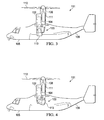
Figure 3 is a side view of the tiltrotor aircraft having the exhaust system, according to the illustrative embodiment of the present application; -
Figure 4 is a side view of the tiltrotor aircraft having the exhaust system, according to the illustrative embodiment of the present application; -
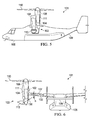
Figure 5 is a side view of the tiltrotor aircraft having the exhaust system, according to the illustrative embodiment of the present application; -
Figure 6 is a rear view of the tiltrotor aircraft having the exhaust system, according to an illustrative embodiment of the present application; -
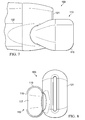
Figure 7 is a side view of an exhaust system, according to an illustrative embodiment of the present application; -
Figure 8 is a rear view of the exhaust system, according to the illustrative embodiment of the present application; -
Figure 9 is a partially removed top view of the exhaust system, according to the illustrative embodiment of the present application; -
Figure 10 is a partially removed rear view of the exhaust system, according to the illustrative embodiment of the present application; -
Figure 11 is a partially removed side view of the exhaust system, according to the illustrative embodiment of the present application; -
Figure 12 is a partially removed bottom view of the exhaust system, according to the illustrative embodiment of the present application; -
Figure 13 is a partially removed side view of the exhaust system, according to the illustrative embodiment of the present application; -
Figure 14 is a partially removed cross-sectional view of the exhaust system, taken at section lines 14-14 inFigure 12 , according to the illustrative embodiment of the present application; and -
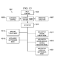
Figure 15 is a schematic view of a control system for controlling the exhaust system, according to an illustrative embodiment of the present application. - Illustrative embodiments of the system are described below. In the interest of clarity, all features of an actual implementation may not be described in this specification. It will of course be appreciated that in the development of any such actual embodiment, numerous implementation-specific decisions must be made to achieve the developer's specific goals, such as compliance with system-related and business-related constraints, which will vary from one implementation to another. Moreover, it will be appreciated that such a development effort might be complex and time-consuming but would nevertheless be a routine undertaking for those of ordinary skill in the art having the benefit of this disclosure.
- In the specification, reference may be made to the spatial relationships between various components and to the spatial orientation of various aspects of components as the devices are depicted in the attached drawings. However, as will be recognized by those skilled in the art after a complete reading of the present application, the devices, members, apparatuses, etc. described herein may be positioned in any desired orientation. Thus, the use of terms such as "above," "below," "upper," "lower," or other like terms to describe a spatial relationship between various components or to describe the spatial orientation of aspects of such components should be understood to describe a relative relationship between the components or a spatial orientation of aspects of such components, respectively, as the system described herein may be oriented in any desired direction.
- Referring to
Figures 1-6 , anexample tiltrotor aircraft 101 is illustrated.Aircraft 101 includes afuselage 105, awing 107 and atail member 109.Rotatable nacelles 111 are coupled to each end portion ofwing 107. Thenacelle 111 located on the left side ofwing 107 is a mirror image of thenacelle 111 located on the right side ofwing 107. Eachnacelle 111 houses a propulsion system including anengine 102, agearbox 104, anddrive shaft 106. A plurality ofrotor blades 110 are operably associated with a drive shaft in eachnacelle 111. -
Aircraft 101 is configured to fly in a helicopter mode, in whichnacelles 111 are positioned approximately vertical. In addition,aircraft 101 is configured to fly in an airplane mode, in whichnacelles 111 are positioned approximately horizontal. It should be appreciated thatnacelles 111 can be oriented at any positioned between vertical and horizontal, which can correspond with flying in a conversion mode. - An
exhaust system 103 is located on eachnacelle 111. For clarity, only theleft side nacelle 111 andexhaust system 103 are detailed herein. Theright side nacelle 111 is a mirror image of theleft side nacelle 111, as one of ordinary skill in the art would fully appreciate having benefit of this disclosure.Exhaust system 103 is configured with avector nozzle 113. Vectornozzle 113 can be selectively rotated in relation toaircraft 101 and/ornacelle 111 in order to achieve certain desirables. For example,vector nozzle 113 can be oriented to provide maximum flight performance, reduce IR signature, or even to reduce/prevent ground heating, as further described herein. - Referring to
Figure 1 ,aircraft 101 is illustrated in an airplane mode withvector nozzle 113 selectively oriented to direct exhaust gases in an aft direction. In such a configuration, thrust from the exhaust gas is directed aftward, thereby contributing to forward propulsion ofaircraft 101. - Referring to
Figure 2 ,aircraft 101 is illustrated in an airplane mode withvector nozzle 113 selectively oriented to direct exhaust gases in an upward direction. In such a configuration, a hot interior portion ofexhaust system 103 is hidden from line-of-site of most potential threats, thereby directionally suppressing the perceived infrared (IR) signature ofaircraft 101. More specifically, a heat seeking weapon deployable from a lower elevation location, as compared to the elevation ofaircraft 101, may not have a line-of-site view of the hot interior portion ofexhaust system 103, whenvector nozzle 113 is positioned accordingly. - Referring to
Figure 3 ,aircraft 101 is illustrated in a helicopter mode withvector nozzle 113 selectively oriented to direct exhaust gases in a downward direction. In such a configuration, thrust from the exhaust gas is directed down, thereby contributing to vertical lift ofaircraft 101. In such a configuration, the hot exhaust gases can contribute to ground heating; however, the directional thrust from the exhaust gas contributes to lift performance ofaircraft 101. - Referring to
Figure 4 ,aircraft 101 is illustrated in a helicopter mode withvector nozzle 113 selectively oriented to direct exhaust gases in an aft direction. In such a configuration, the flow of hot exhaust gas is directed aft so as to reduce/prevent heating of the ground surface below eachnacelle 111. In such a configuration, the directed thrust fromvector nozzle 113 does not contribute or hinder vertical lift of theaircraft 101. However, a hot portion of the interior of theexhaust system 103 may be viewable in a line-of-site view from a position aft of theaircraft 101. - Referring to
Figures 5 and 6 ,aircraft 101 illustrated in a helicopter mode withvector nozzle 113 selectively oriented to direct exhaust gas in an upward/outboard direction. In such a configuration, the directed thrust fromvector nozzle 113 may reduce vertical thrust of theaircraft 101; however, a hot portion of the interior of theexhaust system 103 can be substantially hidden from line-of-sight viewing from ground positions. -
Vector nozzle 113 can be selectively rotated to achieve certain desirables even during rotation ofnacelle 111 between helicopter mode and airplane mode orientations. For example, becausevector nozzle 113 has a nozzlerotational axis 130 that is approximately parallel to a nacellerotational axis 132,vector nozzle 113 can approximately maintain its relative orientation even whilenacelle 111 rotates. The relative angle α between nozzlerotational axis 130 and nacellerotational axis 132 is preferably approximately zero; however, even acute angles, such as less than 20 degrees, can provide desirable results. During operation,aircraft 101 can be in IR suppression mode such thatvector nozzle 113 can be oriented to maintain the direction of exhaust gas in an upward/outboard direction. When tiltrotor 101 is in helicopter mode,vector nozzle 113 can be oriented as shown inFigures 5 and 6 . However, asnacelle 111 is rotated into airplane mode position,vector nozzle 113 can be rotated in the opposite direction (relative to nacelle 111) so that the exhaust gas direction is maintained in an upward/outboard direction. Because the nozzlerotational axis 130 and nacellerotational axis 132 are approximately parallel, the exhaust gas direction can be maintained in an upward/outboard direction through the relative rotation betweennacelle 111 andvector nozzle 113. This feature ofvector nozzle 113 provides for effective suppression of the IR signature through conversion from helicopter mode to airplane mode. - Referring now also to
Figures 7-14 ,exhaust system 103 illustrated in further detail.Vector nozzle 113 can include anouter exhaust duct 115 and aprimary exhaust duct 117.Primary exhaust duct 117 is in gaseous fluid communication with the hot engine exhaust via a main engine fixedexhaust 133. Agap 119 betweenouter exhaust duct 115 andprimary exhaust duct 117 can promote the flow of cooling air between ofouter exhaust duct 115 andprimary exhaust duct 117, so that the IR signature ofexhaust system 103 is reduced. More specifically, cool air from the inside of anexhaust fairing 121 is drawn intogap 119 via aninlet 141, so as to provide cooling between the hotprimary exhaust duct 117 andouter exhaust duct 115. Further,outer exhaust duct 115 at least partially hidesprimary exhaust duct 117 from line-of-site vision. As discussed further herein, certain rotational positions ofvector nozzle 113 hideprimary exhaust duct 117 from line-of-site vision of IR detectors. During operation,primary exhaust duct 117 is considerably hotter thanouter exhaust duct 115. As such,exhaust system 103 is configured to selectively positionvector nozzle 113 to hide ofprimary exhaust duct 117 from line-of-site vision of the predicted threat location. -
Vector nozzle 113 can be selectively rotated with a control system and a vectornozzle pivot assembly 135.Pivot assembly 135 can include apivot drive motor 137 mounted to a non-rotating structure.Drive motor 137 imparts a rotational force uponvector nozzle 113 with aflexible drive belt 131 wrapped around a rotating portion of thevector nozzle 113. It should be appreciated thatpivot drive motor 137 is merely illustrative of a wide variety of actuator systems that may be used to rotatevector nozzle 113. However, with the illustrated geometry, rotation ofvector nozzle 113 can be accomplished with a single pivot joint, thus decreasing complication as compared to other possible vectoring systems. Further,vector nozzle 113 is configured to only rotate about a single axis ofrotation 130, thereby achieving efficiency in the mechanical system. - Referring now in particular to
Figure 14 , a sectional view is illustrated to detail the rotating and non-rotating portions of theexhaust system 103. A thrust bearing includes anon-rotating portion 143 and arotating portion 145. Rotatingportion 145 is coupled to arotating flange 147.Rotating flange 147 is also coupled toprimary exhaust duct 117 and abellows seal 151.Bellows seal 151 presses againstnon-rotating portion 143 of the thrust bearing to create a seal capable of withstanding thermal expansion/contraction.Bellows seal 151 also presses against the main engine fixedexhaust 133. Aflange clamp 149 can be used to secure the flange components. -
Exhaust system 103 illustrated inFigures 7-14 is merely illustrative of a variety of configurations that may be used to allow avector nozzle 113 to selectively rotate adjacent to anon-rotating exhaust 133. - Referring now to
Figure 15 , asystem 1501 is schematically illustrated to detail the functionality and capabilities of the exhaust system of the present application.System 1501 can include apilot input 1503 for allowing the pilot to input desired positions of the vector nozzle. Anautomatic control input 1505 can allow thesystem 1501 to automatically position the vector nozzle. Acontrol system 1509 can receive adata 1507 pertaining to operating conditions of the aircraft. For example,data 1507 can include information related to any perceived threats, the locations of the perceived threats, nacelle position, current aircraft speed/altitude, and current aircraft payload, to name a few.Control system 1509 is configured to send actuation signals to anactuator 1511 in order to selectively position the vector nozzle. Further,control system 1509 determines and dictates the appropriate position of the vector nozzle in part fromdata 1507. - The position of vector nozzle in an
airplane thrust mode 1513 corresponds with the position illustrated inFigure 1 . The position of vector nozzle in an airplaneIR suppression mode 1515 corresponds with the position illustrated inFigure 2 . The position of vector nozzle in a helicopter (hover)thrust mode 1517 corresponds with the position illustrated inFigure 3 . The position of vector nozzle in a helicopter (hover)ground heating mode 1519 corresponds with the position illustrated inFigure 4 . The position of vector nozzle in a helicopter (hover)IR suppression mode 1521 corresponds with the position illustrated inFigures 5 and 6 . - Further, if
operation condition 1507 sends data to controlsystem 1509 indicating that the aircraft is operating in a high enemy threat situation, then controlsystem 1509 can command actuator 1511 to position vector nozzle in airplane IR suppression mode 1515 (when in airplane mode) and helicopter IR suppression mode 1521 (when in a hover). Further, ifoperation condition 1507 sends data to controlsystem 1509 indicating that the aircraft is not operating in a high enemy threat situation and it is desirable to have maximum aircraft performance, then controlsystem 1509 can command actuator 1511 to position vector nozzle in airplane thrust mode 1513 (when in airplane mode) and helicopter thrust mode 1517 (when in a hover). Further, ifoperation condition 1507 sends data to controlsystem 1509 indicating that the aircraft is not operating in a high enemy threat situation and it is desirable to prevent ground surface heating, then controlsystem 1509 can command actuator 1511 to position vector nozzle in helicopter ground heating reduction mode 1519 (when in a hover). It should be appreciated thatsystem 1501 can be configured to positionvector nozzle 113 in hybrid positions, especially during operation of the aircraft between airplane and helicopter modes. - The exhaust system of the present application provides significant advantages, including: 1) providing IR suppression that is threat selectable; 2) providing an exhaust system that can reduce ground heating when in helicopter mode; and 3) providing an exhaust system that can selectively position the thrust vector to increase performance in a variety of flight situations.
- The particular embodiments disclosed above are illustrative only, as the apparatus may be modified and practiced in different but equivalent manners apparent to those skilled in the art having the benefit of the teachings herein. Modifications, additions, or omissions may be made to the apparatuses described herein without departing from the scope of the invention. The components of the apparatus may be integrated or separated. Moreover, the operations of the apparatus may be performed by more, fewer, or other components.
- Furthermore, no limitations are intended to the details of construction or design herein shown, other than as described in the claims below. It is therefore evident that the particular embodiments disclosed above may be altered or modified and all such variations are considered within the scope and spirit of the application. Accordingly, the protection sought herein is as set forth in the claims below.
- To aid the Patent Office, and any readers of any patent issued on this application in interpreting the claims appended hereto, applicants wish to note that they do not intend any of the appended claims to invoke paragraph 6 of 35 U.S.C. § 112 as it exists on the date of filing hereof unless the words "means for" or "step for" are explicitly used in the particular claim.
Claims (16)
the exhaust system according to claim 3 or claim 14, wherein the control system is configured to selectively position the vector nozzle in a helicopter hover ground heating reduction mode such that an exhaust flow is directed in an aftward direction while the nacelle is positioned approximately vertical.
the exhaust system according to claim 3 or claim 14, wherein the control system is configured to selectively position the vector nozzle in a helicopter hover infrared signature suppression mode such that an exhaust flow is directed in an upward direction while the nacelle is positioned approximately vertical.
the exhaust system according to claim 3 or claim 14, wherein the control system is configured to selectively position the vector nozzle in an airplane infrared signature suppression mode such that an exhaust flow is directed in an upward direction while the nacelle is positioned approximately horizontal.
the exhaust system according to claim 3 the vector nozzle further comprising:
Applications Claiming Priority (2)
| Application Number | Priority Date | Filing Date | Title |
|---|---|---|---|
| US201161536650P | 2011-09-20 | 2011-09-20 | |
| US13/584,286 US20140060004A1 (en) | 2011-09-20 | 2012-08-13 | Tiltrotor vectored exhaust system |
Publications (2)
| Publication Number | Publication Date |
|---|---|
| EP2572984A1 true EP2572984A1 (en) | 2013-03-27 |
| EP2572984B1 EP2572984B1 (en) | 2014-03-26 |
Family
ID=46826272
Family Applications (1)
| Application Number | Title | Priority Date | Filing Date |
|---|---|---|---|
| EP12182849.5A Active EP2572984B1 (en) | 2011-09-20 | 2012-09-03 | Vectored exhaust system for tiltrotor aircraft and method |
Country Status (2)
| Country | Link |
|---|---|
| US (1) | US20140060004A1 (en) |
| EP (1) | EP2572984B1 (en) |
Cited By (4)
| Publication number | Priority date | Publication date | Assignee | Title |
|---|---|---|---|---|
| CN103466088A (en) * | 2013-08-23 | 2013-12-25 | 中国航空工业集团公司西安飞机设计研究所 | Nacelle gear tilting mechanism for tilt rotor aircraft |
| EP2837559A1 (en) * | 2013-08-14 | 2015-02-18 | Bell Helicopter Textron Inc. | Fixed engine and rotating proprotor arrangement for a tiltrotor aircraft |
| EP3181455A1 (en) * | 2015-12-16 | 2017-06-21 | AIRBUS HELICOPTERS DEUTSCHLAND GmbH | An aircraft with a hot air exhaust that comprises two pivotally mounted exhaust sections |
| US9834303B2 (en) | 2013-08-14 | 2017-12-05 | Bell Helicopter Textron Inc. | Method and apparatus of connecting a fixed drive system to a rotating drive system for a tiltrotor aircraft |
Families Citing this family (10)
| Publication number | Priority date | Publication date | Assignee | Title |
|---|---|---|---|---|
| US10926874B2 (en) * | 2016-01-15 | 2021-02-23 | Aurora Flight Sciences Corporation | Hybrid propulsion vertical take-off and landing aircraft |
| RU2674731C1 (en) * | 2017-06-13 | 2018-12-12 | Николай Алексеевич Цуриков | High speed helicopter |
| US10822101B2 (en) | 2017-07-21 | 2020-11-03 | General Electric Company | Vertical takeoff and landing aircraft having a forward thrust propulsor |
| US10480386B2 (en) | 2017-09-22 | 2019-11-19 | Bell Helicopter Textron Inc. | Exhaust manifold for combining system exhaust plume |
| US20190256202A1 (en) | 2018-02-19 | 2019-08-22 | Parallel Flight Technologies, Inc. | Method and apparatus for lifting a payload |
| US11148820B1 (en) | 2018-02-19 | 2021-10-19 | Parallel Flight Technologies, Inc. | System defining a hybrid power unit for thrust generation in an aerial vehicle and method for controlling the same |
| US11643198B2 (en) * | 2019-01-15 | 2023-05-09 | Curtis Miller | Vertical lift single engine vehicle system |
| US11279479B2 (en) | 2020-03-28 | 2022-03-22 | Textron Innovations Inc. | Fluidic yaw control systems for use in hover |
| US11858632B2 (en) | 2020-12-28 | 2024-01-02 | Parallel Flight Technologies, Inc. | System defining a hybrid power unit for thrust generation in an aerial vehicle and method for controlling the same |
| JP7838755B2 (en) * | 2022-03-29 | 2026-04-01 | 株式会社石川エナジーリサーチ | flight equipment |
Citations (3)
| Publication number | Priority date | Publication date | Assignee | Title |
|---|---|---|---|---|
| FR1373010A (en) * | 1961-12-07 | 1964-09-25 | Bristol Siddeley Engines Ltd | Aircraft engine unit |
| FR2039324A1 (en) * | 1969-04-21 | 1971-01-15 | Westland Aircraft Ltd | |
| WO1991005704A1 (en) * | 1989-10-16 | 1991-05-02 | Bell Helicopter Textron Inc. | Drive system for tiltrotor aircraft |
Family Cites Families (13)
| Publication number | Priority date | Publication date | Assignee | Title |
|---|---|---|---|---|
| US2231239A (en) * | 1939-05-16 | 1941-02-11 | Curtiss Wright Corp | Cowling exhaust outlet |
| GB1033429A (en) * | 1964-10-10 | 1966-06-22 | Rolls Royce | Improvements in or relating to aircraft |
| US4312480A (en) * | 1979-11-26 | 1982-01-26 | Hughes Helicopters, Inc. | Radiation shielding and gas diffusion apparatus |
| FR2565293B1 (en) * | 1984-06-04 | 1986-10-17 | Aerospatiale | JET DIFFERER-DEVIATOR ASSEMBLY FOR AERODYNE TURBOMOTOR |
| US4732324A (en) * | 1984-12-19 | 1988-03-22 | Rolls-Royce Inc. | Variable flow area nozzle |
| US5197855A (en) * | 1991-07-01 | 1993-03-30 | United Technologies Corporation | Engine exhaust/blade interaction noise suppression |
| US6109562A (en) * | 1998-04-22 | 2000-08-29 | Pratt & Whitney Canada Corp. | Aircraft construction |
| US6296378B1 (en) * | 1999-06-23 | 2001-10-02 | Bell Helicopter Textron, Inc. | Position light for aircraft |
| US6382556B1 (en) * | 1999-12-20 | 2002-05-07 | Roger N. C. Pham | VTOL airplane with only one tiltable prop-rotor |
| US6969028B2 (en) * | 2003-01-22 | 2005-11-29 | The Boeing Company | Scarf nozzle for a jet engine and method of using the same |
| DE07873413T1 (en) * | 2006-06-09 | 2009-07-30 | Bell Helicopter Textron, Inc., Fort Worth | ENGINE EXHAUST SYSTEM WITH DIRECTIONAL NOZZLE |
| DE102007061995B4 (en) * | 2007-12-21 | 2012-03-01 | Airbus Operations Gmbh | Device for the mechanically decoupled attachment of an aircraft component through which hot gas flows |
| JP2009235971A (en) * | 2008-03-26 | 2009-10-15 | Mitsubishi Heavy Ind Ltd | Seal member, steam turbine, and method of avoiding resonance |
-
2012
- 2012-08-13 US US13/584,286 patent/US20140060004A1/en not_active Abandoned
- 2012-09-03 EP EP12182849.5A patent/EP2572984B1/en active Active
Patent Citations (3)
| Publication number | Priority date | Publication date | Assignee | Title |
|---|---|---|---|---|
| FR1373010A (en) * | 1961-12-07 | 1964-09-25 | Bristol Siddeley Engines Ltd | Aircraft engine unit |
| FR2039324A1 (en) * | 1969-04-21 | 1971-01-15 | Westland Aircraft Ltd | |
| WO1991005704A1 (en) * | 1989-10-16 | 1991-05-02 | Bell Helicopter Textron Inc. | Drive system for tiltrotor aircraft |
Cited By (10)
| Publication number | Priority date | Publication date | Assignee | Title |
|---|---|---|---|---|
| EP2837559A1 (en) * | 2013-08-14 | 2015-02-18 | Bell Helicopter Textron Inc. | Fixed engine and rotating proprotor arrangement for a tiltrotor aircraft |
| US9174731B2 (en) | 2013-08-14 | 2015-11-03 | Bell Helicopter Textron Inc. | Fixed engine and rotating proprotor arrangement for a tiltrotor aircraft |
| US9834303B2 (en) | 2013-08-14 | 2017-12-05 | Bell Helicopter Textron Inc. | Method and apparatus of connecting a fixed drive system to a rotating drive system for a tiltrotor aircraft |
| CN103466088A (en) * | 2013-08-23 | 2013-12-25 | 中国航空工业集团公司西安飞机设计研究所 | Nacelle gear tilting mechanism for tilt rotor aircraft |
| EP3181455A1 (en) * | 2015-12-16 | 2017-06-21 | AIRBUS HELICOPTERS DEUTSCHLAND GmbH | An aircraft with a hot air exhaust that comprises two pivotally mounted exhaust sections |
| CN106882392A (en) * | 2015-12-16 | 2017-06-23 | 空客直升机德国有限公司 | The aircraft of the exhaust of hot air part with the discharge section being pivotally mounted on including two |
| KR20170072130A (en) * | 2015-12-16 | 2017-06-26 | 에어버스 헬리콥터스 도이칠란트 게엠베하 | An aircraft with a hot air exhaust that comprises two pivotally mounted exhaust sections |
| KR101857211B1 (en) * | 2015-12-16 | 2018-06-20 | 에어버스 헬리콥터스 도이칠란트 게엠베하 | An aircraft with a hot air exhaust that comprises two pivotally mounted exhaust sections |
| CN106882392B (en) * | 2015-12-16 | 2019-09-03 | 空客直升机德国有限公司 | Aircraft with hot air discharge including two pivotally mounted discharge sections |
| US10527000B2 (en) | 2015-12-16 | 2020-01-07 | Airbus Helicopters Deutschland GmbH | Aircraft with a hot air exhaust that comprises two pivotally mounted exhaust sections |
Also Published As
| Publication number | Publication date |
|---|---|
| EP2572984B1 (en) | 2014-03-26 |
| US20140060004A1 (en) | 2014-03-06 |
Similar Documents
| Publication | Publication Date | Title |
|---|---|---|
| EP2572984B1 (en) | Vectored exhaust system for tiltrotor aircraft and method | |
| US11518504B2 (en) | Compound helicopters having auxiliary propulsive systems | |
| US11267579B2 (en) | Compound helicopters having hybrid propulsion engines | |
| US8469308B2 (en) | Aircraft wing extension and nozzle system | |
| EP2808253B1 (en) | Helicopter with cross flow fan | |
| US9862486B2 (en) | Vertical takeoff and landing aircraft | |
| US20190329858A1 (en) | Aircraft Drag Reduction System And Internally Cooled Electric Motor System And Aircraft Using Same | |
| CN111301692A (en) | Motor cooling system and method | |
| US11926429B2 (en) | Aircraft having cooling system for distributing heat transfer liquid to different regions of aircraft | |
| US8636243B2 (en) | Anti-torque nozzle system with internal sleeve valve for a rotorcraft | |
| US8636244B2 (en) | Propulsive anti-torque nozzle system with rotating thrust director for a rotorcraft | |
| KR101654505B1 (en) | Equipped with thrust controls of controlled variable pitch type drone | |
| CN112424065B (en) | Aircraft propulsion and torque mitigation technology | |
| EP3330182A1 (en) | Low infrared signature exhaust through active film cooling, active mixing and active vane rotation | |
| US8910464B2 (en) | Lift fan spherical thrust vectoring nozzle | |
| US20200070994A1 (en) | Engine Exhaust Suppressor | |
| CA2789329C (en) | Tiltrotor vectored exhaust system | |
| US20200231293A1 (en) | Dedicated core inflow inlet for convertible engine | |
| US20170175673A1 (en) | Aircraft with a hot air exhaust that comprises two pivotally mounted exhaust sections | |
| US20190315461A1 (en) | Rotary-winged vehicle systems and devices | |
| US20220128013A1 (en) | Takeoff power boost | |
| US11332241B2 (en) | Centrifugal fans for vertical take-off and landing (VTOL) aircraft propulsion | |
| US20170121033A1 (en) | Convertible engine exhaust for rotocraft | |
| US20260077855A1 (en) | Aircraft having a propulsion system | |
| KR101150855B1 (en) | Flight control structure of duct type flight robot |
Legal Events
| Date | Code | Title | Description |
|---|---|---|---|
| PUAI | Public reference made under article 153(3) epc to a published international application that has entered the european phase |
Free format text: ORIGINAL CODE: 0009012 |
|
| 17P | Request for examination filed |
Effective date: 20120903 |
|
| AK | Designated contracting states |
Kind code of ref document: A1 Designated state(s): AL AT BE BG CH CY CZ DE DK EE ES FI FR GB GR HR HU IE IS IT LI LT LU LV MC MK MT NL NO PL PT RO RS SE SI SK SM TR |
|
| AX | Request for extension of the european patent |
Extension state: BA ME |
|
| GRAP | Despatch of communication of intention to grant a patent |
Free format text: ORIGINAL CODE: EPIDOSNIGR1 |
|
| INTG | Intention to grant announced |
Effective date: 20130603 |
|
| GRAS | Grant fee paid |
Free format text: ORIGINAL CODE: EPIDOSNIGR3 |
|
| GRAA | (expected) grant |
Free format text: ORIGINAL CODE: 0009210 |
|
| AK | Designated contracting states |
Kind code of ref document: B1 Designated state(s): AL AT BE BG CH CY CZ DE DK EE ES FI FR GB GR HR HU IE IS IT LI LT LU LV MC MK MT NL NO PL PT RO RS SE SI SK SM TR |
|
| REG | Reference to a national code |
Ref country code: GB Ref legal event code: FG4D |
|
| REG | Reference to a national code |
Ref country code: CH Ref legal event code: EP |
|
| REG | Reference to a national code |
Ref country code: AT Ref legal event code: REF Ref document number: 658835 Country of ref document: AT Kind code of ref document: T Effective date: 20140415 |
|
| REG | Reference to a national code |
Ref country code: IE Ref legal event code: FG4D |
|
| REG | Reference to a national code |
Ref country code: DE Ref legal event code: R096 Ref document number: 602012001213 Country of ref document: DE Effective date: 20140508 |
|
| PG25 | Lapsed in a contracting state [announced via postgrant information from national office to epo] |
Ref country code: LT Free format text: LAPSE BECAUSE OF FAILURE TO SUBMIT A TRANSLATION OF THE DESCRIPTION OR TO PAY THE FEE WITHIN THE PRESCRIBED TIME-LIMIT Effective date: 20140326 Ref country code: NO Free format text: LAPSE BECAUSE OF FAILURE TO SUBMIT A TRANSLATION OF THE DESCRIPTION OR TO PAY THE FEE WITHIN THE PRESCRIBED TIME-LIMIT Effective date: 20140626 |
|
| REG | Reference to a national code |
Ref country code: AT Ref legal event code: MK05 Ref document number: 658835 Country of ref document: AT Kind code of ref document: T Effective date: 20140326 |
|
| REG | Reference to a national code |
Ref country code: NL Ref legal event code: VDEP Effective date: 20140326 |
|
| REG | Reference to a national code |
Ref country code: LT Ref legal event code: MG4D |
|
| PG25 | Lapsed in a contracting state [announced via postgrant information from national office to epo] |
Ref country code: FI Free format text: LAPSE BECAUSE OF FAILURE TO SUBMIT A TRANSLATION OF THE DESCRIPTION OR TO PAY THE FEE WITHIN THE PRESCRIBED TIME-LIMIT Effective date: 20140326 Ref country code: SE Free format text: LAPSE BECAUSE OF FAILURE TO SUBMIT A TRANSLATION OF THE DESCRIPTION OR TO PAY THE FEE WITHIN THE PRESCRIBED TIME-LIMIT Effective date: 20140326 |
|
| PG25 | Lapsed in a contracting state [announced via postgrant information from national office to epo] |
Ref country code: RS Free format text: LAPSE BECAUSE OF FAILURE TO SUBMIT A TRANSLATION OF THE DESCRIPTION OR TO PAY THE FEE WITHIN THE PRESCRIBED TIME-LIMIT Effective date: 20140326 Ref country code: LV Free format text: LAPSE BECAUSE OF FAILURE TO SUBMIT A TRANSLATION OF THE DESCRIPTION OR TO PAY THE FEE WITHIN THE PRESCRIBED TIME-LIMIT Effective date: 20140326 Ref country code: HR Free format text: LAPSE BECAUSE OF FAILURE TO SUBMIT A TRANSLATION OF THE DESCRIPTION OR TO PAY THE FEE WITHIN THE PRESCRIBED TIME-LIMIT Effective date: 20140326 |
|
| PG25 | Lapsed in a contracting state [announced via postgrant information from national office to epo] |
Ref country code: NL Free format text: LAPSE BECAUSE OF FAILURE TO SUBMIT A TRANSLATION OF THE DESCRIPTION OR TO PAY THE FEE WITHIN THE PRESCRIBED TIME-LIMIT Effective date: 20140326 Ref country code: CZ Free format text: LAPSE BECAUSE OF FAILURE TO SUBMIT A TRANSLATION OF THE DESCRIPTION OR TO PAY THE FEE WITHIN THE PRESCRIBED TIME-LIMIT Effective date: 20140326 Ref country code: BE Free format text: LAPSE BECAUSE OF FAILURE TO SUBMIT A TRANSLATION OF THE DESCRIPTION OR TO PAY THE FEE WITHIN THE PRESCRIBED TIME-LIMIT Effective date: 20140326 Ref country code: IS Free format text: LAPSE BECAUSE OF FAILURE TO SUBMIT A TRANSLATION OF THE DESCRIPTION OR TO PAY THE FEE WITHIN THE PRESCRIBED TIME-LIMIT Effective date: 20140726 Ref country code: EE Free format text: LAPSE BECAUSE OF FAILURE TO SUBMIT A TRANSLATION OF THE DESCRIPTION OR TO PAY THE FEE WITHIN THE PRESCRIBED TIME-LIMIT Effective date: 20140326 Ref country code: RO Free format text: LAPSE BECAUSE OF FAILURE TO SUBMIT A TRANSLATION OF THE DESCRIPTION OR TO PAY THE FEE WITHIN THE PRESCRIBED TIME-LIMIT Effective date: 20140326 Ref country code: BG Free format text: LAPSE BECAUSE OF FAILURE TO SUBMIT A TRANSLATION OF THE DESCRIPTION OR TO PAY THE FEE WITHIN THE PRESCRIBED TIME-LIMIT Effective date: 20140626 Ref country code: CY Free format text: LAPSE BECAUSE OF FAILURE TO SUBMIT A TRANSLATION OF THE DESCRIPTION OR TO PAY THE FEE WITHIN THE PRESCRIBED TIME-LIMIT Effective date: 20140326 |
|
| PG25 | Lapsed in a contracting state [announced via postgrant information from national office to epo] |
Ref country code: PL Free format text: LAPSE BECAUSE OF FAILURE TO SUBMIT A TRANSLATION OF THE DESCRIPTION OR TO PAY THE FEE WITHIN THE PRESCRIBED TIME-LIMIT Effective date: 20140326 Ref country code: AT Free format text: LAPSE BECAUSE OF FAILURE TO SUBMIT A TRANSLATION OF THE DESCRIPTION OR TO PAY THE FEE WITHIN THE PRESCRIBED TIME-LIMIT Effective date: 20140326 Ref country code: SK Free format text: LAPSE BECAUSE OF FAILURE TO SUBMIT A TRANSLATION OF THE DESCRIPTION OR TO PAY THE FEE WITHIN THE PRESCRIBED TIME-LIMIT Effective date: 20140326 Ref country code: ES Free format text: LAPSE BECAUSE OF FAILURE TO SUBMIT A TRANSLATION OF THE DESCRIPTION OR TO PAY THE FEE WITHIN THE PRESCRIBED TIME-LIMIT Effective date: 20140326 |
|
| PG25 | Lapsed in a contracting state [announced via postgrant information from national office to epo] |
Ref country code: PT Free format text: LAPSE BECAUSE OF FAILURE TO SUBMIT A TRANSLATION OF THE DESCRIPTION OR TO PAY THE FEE WITHIN THE PRESCRIBED TIME-LIMIT Effective date: 20140728 |
|
| REG | Reference to a national code |
Ref country code: DE Ref legal event code: R097 Ref document number: 602012001213 Country of ref document: DE |
|
| PG25 | Lapsed in a contracting state [announced via postgrant information from national office to epo] |
Ref country code: DK Free format text: LAPSE BECAUSE OF FAILURE TO SUBMIT A TRANSLATION OF THE DESCRIPTION OR TO PAY THE FEE WITHIN THE PRESCRIBED TIME-LIMIT Effective date: 20140326 |
|
| PLBE | No opposition filed within time limit |
Free format text: ORIGINAL CODE: 0009261 |
|
| STAA | Information on the status of an ep patent application or granted ep patent |
Free format text: STATUS: NO OPPOSITION FILED WITHIN TIME LIMIT |
|
| 26N | No opposition filed |
Effective date: 20150106 |
|
| REG | Reference to a national code |
Ref country code: DE Ref legal event code: R097 Ref document number: 602012001213 Country of ref document: DE Effective date: 20150106 |
|
| PG25 | Lapsed in a contracting state [announced via postgrant information from national office to epo] |
Ref country code: LU Free format text: LAPSE BECAUSE OF FAILURE TO SUBMIT A TRANSLATION OF THE DESCRIPTION OR TO PAY THE FEE WITHIN THE PRESCRIBED TIME-LIMIT Effective date: 20140903 Ref country code: MC Free format text: LAPSE BECAUSE OF FAILURE TO SUBMIT A TRANSLATION OF THE DESCRIPTION OR TO PAY THE FEE WITHIN THE PRESCRIBED TIME-LIMIT Effective date: 20140326 |
|
| REG | Reference to a national code |
Ref country code: IE Ref legal event code: MM4A |
|
| PG25 | Lapsed in a contracting state [announced via postgrant information from national office to epo] |
Ref country code: SI Free format text: LAPSE BECAUSE OF FAILURE TO SUBMIT A TRANSLATION OF THE DESCRIPTION OR TO PAY THE FEE WITHIN THE PRESCRIBED TIME-LIMIT Effective date: 20140326 |
|
| PG25 | Lapsed in a contracting state [announced via postgrant information from national office to epo] |
Ref country code: IE Free format text: LAPSE BECAUSE OF NON-PAYMENT OF DUE FEES Effective date: 20140903 |
|
| REG | Reference to a national code |
Ref country code: CH Ref legal event code: PL |
|
| PG25 | Lapsed in a contracting state [announced via postgrant information from national office to epo] |
Ref country code: SM Free format text: LAPSE BECAUSE OF FAILURE TO SUBMIT A TRANSLATION OF THE DESCRIPTION OR TO PAY THE FEE WITHIN THE PRESCRIBED TIME-LIMIT Effective date: 20140326 |
|
| PG25 | Lapsed in a contracting state [announced via postgrant information from national office to epo] |
Ref country code: GR Free format text: LAPSE BECAUSE OF FAILURE TO SUBMIT A TRANSLATION OF THE DESCRIPTION OR TO PAY THE FEE WITHIN THE PRESCRIBED TIME-LIMIT Effective date: 20140627 Ref country code: MT Free format text: LAPSE BECAUSE OF FAILURE TO SUBMIT A TRANSLATION OF THE DESCRIPTION OR TO PAY THE FEE WITHIN THE PRESCRIBED TIME-LIMIT Effective date: 20140326 |
|
| PG25 | Lapsed in a contracting state [announced via postgrant information from national office to epo] |
Ref country code: CH Free format text: LAPSE BECAUSE OF NON-PAYMENT OF DUE FEES Effective date: 20150930 Ref country code: LI Free format text: LAPSE BECAUSE OF NON-PAYMENT OF DUE FEES Effective date: 20150930 Ref country code: TR Free format text: LAPSE BECAUSE OF FAILURE TO SUBMIT A TRANSLATION OF THE DESCRIPTION OR TO PAY THE FEE WITHIN THE PRESCRIBED TIME-LIMIT Effective date: 20140326 Ref country code: HU Free format text: LAPSE BECAUSE OF FAILURE TO SUBMIT A TRANSLATION OF THE DESCRIPTION OR TO PAY THE FEE WITHIN THE PRESCRIBED TIME-LIMIT; INVALID AB INITIO Effective date: 20120903 |
|
| REG | Reference to a national code |
Ref country code: FR Ref legal event code: PLFP Year of fee payment: 5 |
|
| REG | Reference to a national code |
Ref country code: FR Ref legal event code: PLFP Year of fee payment: 6 |
|
| PG25 | Lapsed in a contracting state [announced via postgrant information from national office to epo] |
Ref country code: MK Free format text: LAPSE BECAUSE OF FAILURE TO SUBMIT A TRANSLATION OF THE DESCRIPTION OR TO PAY THE FEE WITHIN THE PRESCRIBED TIME-LIMIT Effective date: 20140326 |
|
| REG | Reference to a national code |
Ref country code: FR Ref legal event code: PLFP Year of fee payment: 7 |
|
| PG25 | Lapsed in a contracting state [announced via postgrant information from national office to epo] |
Ref country code: AL Free format text: LAPSE BECAUSE OF FAILURE TO SUBMIT A TRANSLATION OF THE DESCRIPTION OR TO PAY THE FEE WITHIN THE PRESCRIBED TIME-LIMIT Effective date: 20140326 |
|
| PGFP | Annual fee paid to national office [announced via postgrant information from national office to epo] |
Ref country code: IT Payment date: 20210922 Year of fee payment: 10 |
|
| PGFP | Annual fee paid to national office [announced via postgrant information from national office to epo] |
Ref country code: GB Payment date: 20210927 Year of fee payment: 10 |
|
| GBPC | Gb: european patent ceased through non-payment of renewal fee |
Effective date: 20220903 |
|
| P01 | Opt-out of the competence of the unified patent court (upc) registered |
Effective date: 20230602 |
|
| PG25 | Lapsed in a contracting state [announced via postgrant information from national office to epo] |
Ref country code: IT Free format text: LAPSE BECAUSE OF NON-PAYMENT OF DUE FEES Effective date: 20220903 Ref country code: GB Free format text: LAPSE BECAUSE OF NON-PAYMENT OF DUE FEES Effective date: 20220903 |
|
| PGFP | Annual fee paid to national office [announced via postgrant information from national office to epo] |
Ref country code: DE Payment date: 20250929 Year of fee payment: 14 |
|
| PGFP | Annual fee paid to national office [announced via postgrant information from national office to epo] |
Ref country code: FR Payment date: 20250925 Year of fee payment: 14 |