EP2572408B1 - Airline passenger seat modular user interface device - Google Patents
Airline passenger seat modular user interface device Download PDFInfo
- Publication number
- EP2572408B1 EP2572408B1 EP11784060.3A EP11784060A EP2572408B1 EP 2572408 B1 EP2572408 B1 EP 2572408B1 EP 11784060 A EP11784060 A EP 11784060A EP 2572408 B1 EP2572408 B1 EP 2572408B1
- Authority
- EP
- European Patent Office
- Prior art keywords
- display unit
- video display
- interface modules
- passenger interface
- sockets
- Prior art date
- Legal status (The legal status is an assumption and is not a legal conclusion. Google has not performed a legal analysis and makes no representation as to the accuracy of the status listed.)
- Active
Links
Images

Classifications
-
- B—PERFORMING OPERATIONS; TRANSPORTING
- B60—VEHICLES IN GENERAL
- B60R—VEHICLES, VEHICLE FITTINGS, OR VEHICLE PARTS, NOT OTHERWISE PROVIDED FOR
- B60R11/00—Arrangements for holding or mounting articles, not otherwise provided for
- B60R11/02—Arrangements for holding or mounting articles, not otherwise provided for for radio sets, television sets, telephones, or the like; Arrangement of controls thereof
- B60R11/0229—Arrangements for holding or mounting articles, not otherwise provided for for radio sets, television sets, telephones, or the like; Arrangement of controls thereof for displays, e.g. cathodic tubes
- B60R11/0235—Arrangements for holding or mounting articles, not otherwise provided for for radio sets, television sets, telephones, or the like; Arrangement of controls thereof for displays, e.g. cathodic tubes of flat type, e.g. LCD
-
- B—PERFORMING OPERATIONS; TRANSPORTING
- B60—VEHICLES IN GENERAL
- B60N—SEATS SPECIALLY ADAPTED FOR VEHICLES; VEHICLE PASSENGER ACCOMMODATION NOT OTHERWISE PROVIDED FOR
- B60N2/00—Seats specially adapted for vehicles; Arrangement or mounting of seats in vehicles
- B60N2/02—Seats specially adapted for vehicles; Arrangement or mounting of seats in vehicles the seat or part thereof being movable, e.g. adjustable
- B60N2/0224—Non-manual adjustments, e.g. with electrical operation
- B60N2/0244—Non-manual adjustments, e.g. with electrical operation with logic circuits
- B60N2/0264—Non-manual adjustments, e.g. with electrical operation with logic circuits characterised by the type of electrical connection, e.g. wiring, plugs or USB
-
- B—PERFORMING OPERATIONS; TRANSPORTING
- B64—AIRCRAFT; AVIATION; COSMONAUTICS
- B64D—EQUIPMENT FOR FITTING IN OR TO AIRCRAFT; FLIGHT SUITS; PARACHUTES; ARRANGEMENT OR MOUNTING OF POWER PLANTS OR PROPULSION TRANSMISSIONS IN AIRCRAFT
- B64D11/00—Passenger or crew accommodation; Flight-deck installations not otherwise provided for
- B64D11/0015—Arrangements for entertainment or communications, e.g. radio, television
-
- B—PERFORMING OPERATIONS; TRANSPORTING
- B64—AIRCRAFT; AVIATION; COSMONAUTICS
- B64D—EQUIPMENT FOR FITTING IN OR TO AIRCRAFT; FLIGHT SUITS; PARACHUTES; ARRANGEMENT OR MOUNTING OF POWER PLANTS OR PROPULSION TRANSMISSIONS IN AIRCRAFT
- B64D11/00—Passenger or crew accommodation; Flight-deck installations not otherwise provided for
- B64D11/0015—Arrangements for entertainment or communications, e.g. radio, television
- B64D11/00153—Monitors mounted on or in the seat other than the seat back
-
- B—PERFORMING OPERATIONS; TRANSPORTING
- B64—AIRCRAFT; AVIATION; COSMONAUTICS
- B64D—EQUIPMENT FOR FITTING IN OR TO AIRCRAFT; FLIGHT SUITS; PARACHUTES; ARRANGEMENT OR MOUNTING OF POWER PLANTS OR PROPULSION TRANSMISSIONS IN AIRCRAFT
- B64D11/00—Passenger or crew accommodation; Flight-deck installations not otherwise provided for
- B64D11/06—Arrangements of seats, or adaptations or details specially adapted for aircraft seats
- B64D11/0602—Seat modules, i.e. seat systems including furniture separate from the seat itself
-
- B—PERFORMING OPERATIONS; TRANSPORTING
- B64—AIRCRAFT; AVIATION; COSMONAUTICS
- B64D—EQUIPMENT FOR FITTING IN OR TO AIRCRAFT; FLIGHT SUITS; PARACHUTES; ARRANGEMENT OR MOUNTING OF POWER PLANTS OR PROPULSION TRANSMISSIONS IN AIRCRAFT
- B64D11/00—Passenger or crew accommodation; Flight-deck installations not otherwise provided for
- B64D11/06—Arrangements of seats, or adaptations or details specially adapted for aircraft seats
- B64D11/0624—Arrangements of electrical connectors, e.g. for earphone, internet or electric supply
-
- B—PERFORMING OPERATIONS; TRANSPORTING
- B60—VEHICLES IN GENERAL
- B60R—VEHICLES, VEHICLE FITTINGS, OR VEHICLE PARTS, NOT OTHERWISE PROVIDED FOR
- B60R11/00—Arrangements for holding or mounting articles, not otherwise provided for
- B60R2011/0001—Arrangements for holding or mounting articles, not otherwise provided for characterised by position
- B60R2011/0003—Arrangements for holding or mounting articles, not otherwise provided for characterised by position inside the vehicle
- B60R2011/0012—Seats or parts thereof
Definitions
- the present invention relates to the field of modular user interfaces for computer-based systems used in vehicles, particularly to in-flight entertainment (IFE) systems.
- IFE in-flight entertainment
- IFE systems provide passengers with a wide range of entertainment options, from listening to audio, watching video, playing video games, etc.
- US 2002/0195523 discloses a seat track mounted passenger interface device.
- the device includes a base removably coupled to an aircraft seat track.
- a riser coupled to the base extends generally vertically away from the seat track.
- An interface head coupled to the distal end of the riser is located adjacent a passenger seat bottom cushion.
- One or more jacks and/or sockets are disposed within the interface head. Electrical leads interconnect the jacks and/or sockets with a power source. The electrical leads extend from the interface head, through the riser and base, and then through the seat track raceway.
- WO 2008/014352 discloses a mounting system suitable for use with user interface devices and methods for manufacturing and using same.
- the mounting system can be installed at any suitable location and, once installed, can receive and engage a selected user interface device.
- the user interface device thereby can select and present viewing content and, when not in use, can be stowed in a manner that does not interfere with the user.
- Being provided as modular units, a malfunctioning user interface device can be easily removed from the mounting system and replaced with another user interface device, minimizing inconvenience to the user and facilitating repairs
- a video display unit for a vehicle comprising a module carrier unit according to claim is provided.
- Passenger interface modules having a predefined shape and size, and each containing a different interface unit, can be plugged into various sockets of the communication unit. When one of the modules becomes non-functional, or a different configuration is desired, the modules can easily be removed and replaced.
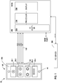
- FIG. 1 illustrates a system using an exemplary embodiment of a module carrier unit 10 that connects into an entertainment system 200, 300 of a vehicle.
- a primary server 300 comprises storage that is used to store entertainment-related data, such as multi-media content, programs, such as games, and other related data and programs that might be of interest to a vehicle passenger.
- entertainment-related data such as multi-media content
- programs such as games, and other related data and programs that might be of interest to a vehicle passenger.
- a seat video display unit (SVDU) 200 is located near the seat of the passenger and comprises an interface back to the server 300 over which entertainment system-related data is transmitted.
- the SVDU 200 comprises, among other things, a processor 210, an I/O adapter 220 for communicating both with the carrier unit 10 and the server 300, and a display 230, such as an LCD, LED, plasma, touchscreen, or other type of known display.
- the SVDU 200 contains hardware and software for processing multi-media or other related data.
- the carrier unit 10 may be located in an arm rest, near the display, or any other location that is readily accessible by a seated passenger.
- the carrier unit 10 could be mounted in a cavity of the seating area (not shown) of a size designed to accept the unit 10.
- the mounting could comprise fasteners, such as screws, bolts, and the like, but could also include various locking mechanisms such as slots and tabs, and the like.
- a communications interface 100 is provided between the carrier unit 10 and the SVDU 200.
- This interface 100 can provide two-way communications that includes information such as video data, audio data, user interface control data, game data, etc.
- the communications interface 100 comprises two USB lines, a video line, an audio line, and a power line that may be used to power the carrier unit 100.
- the carrier unit 100 connects to the I/O adapter 220 of the SVDU 200. This connection can be either hardwired or could use any connector of a suitable grade. Similarly, the connection to the carrier unit 10 can be hardwired or use a similar connector.
- the personal carrier unit 10 comprises a number of passenger interface modules (smart Passenger Interface Module-PIM) 20.
- the exemplary modules shown include an RCA video jack module 20.1, RCA audio left and right jack module 20.2, an audio headphone module 20.3, and a USB module 20.4.
- Other modules can be envisioned, such as a DIN connector module, a module that permits turning an overhead light on and off, and an attendant call/cancel button.
- the carrier unit 10 comprises an outer case 40 made up of a bottom portion 40a and a faceplate 40b that can be affixed to the bottom portion 40a with one or more fasteners 44.
- the faceplate 40b could also be affixed using tabs, slots, and the like, as well. Holes in the faceplate 40b can be used to help secure the modules 20 into the carrier unit 10.
- the bottom portion 40a may comprise a group of similarly shaped and sized sockets 42, into which the passenger interface modules 20 are inserted.
- the modules 20 are designed with a common shape and size so that any module 20 can plug into any socket 42.
- a common interface between the modules 20 and the sockets 42 is defined.
- the modules 20 may comprise a connector 22 in the form of pins, electrical contacts, etc. that are designed to mate with corresponding sockets or electrical contacts 43 that form a bus 45 of the carrier unit 10.
- a module lock 47 may be provided to help ensure that the modules remain in the socket. Such a lock could be formed, e.g., by a sliding mechanism that slides an interfering surface on top of a surface of the module that prevents its removal from the socket 42 via an interference fit. Such locks 47 could be placed on both sides of the module 20, and could be placed adjacent to each module 20.
- the modules 20 themselves are designed to be relatively easy to remove from the sockets 42 and replace. This may involve, e.g., removing the faceplate 40b, releasing the module lock 47, or other simple mechanical procedures.
- the module 20 is preferably not more permanently affixed in the sockets 42 through the use, e.g., of soldered wires, adhesives, and the like.
- the modules 20 are very simply designed.
- the audio connectors can be designed simply to pass through the analog audio signal via a simple pair of conductors to corresponding lines on the bus 45 of the carrier unit 10.
- digital communication modules 20, such as a USB 2.0 connector can simply pass through the signals directly via connectors to the bus 45. This is consistent with keeping the cost of the modules 20 very inexpensive and easy to replace if they are damaged. Furthermore, with a very simple design, the likelihood of failure is relatively small.
- the modules can comprise electronic circuitry or even processors for handling complex signal processing, such as MP3 conversion to audio signals, video decompression and decoding, wireless communications (e.g., Wi-Fi, Bluetooth), etc.
- Modules such as a web camera and microphone could also be included.
- the carrier unit 10 is designed to be of a size to fit in an existing footprint for such controls in present airplanes. Therefore, although any number of sockets 42 could be provided, a preferred embodiment uses four sockets 42. As can be seen in the example presented above, where the number or size of the interface device, such as the RCA audio/video, makes it impossible to fit on a single module 20, the interface can be split across multiple modules 20.
- the carrier unit 10 may comprise a printed circuit board (PCB) 60 upon which the socket connectors 43 are positioned.
- the PCB 60 may also comprise a processor, volatile and non-volatile memory, and the I/O adapter 50, as well as other circuitry, such as level shifting circuitry, analog-to-digital (A/D) and digital-to-analog (D/A) converters, and other signal conditioning circuitry to translate signals received from user devices to the SVDU 200, and vice versa.
- the processor and software may also comprise algorithms for handling various communications protocols that can be utilized both by user devices and for communicating with the SVDU 200.
- the module type is automatically determined and the carrier unit 10 contains circuitry that permits it to accommodate and adapt to the functional needs of the module 20 that is inserted.
- the communications bus 100 can be shared between the carriers 10. This can be the case in which a plurality of carrier units 10 are tethered together, where one carrier unit 10 is (or multiple carrier units 10 are) mounted, e.g., on the SVDU 200, or in any other mounting or configuration of the carrier units 10.
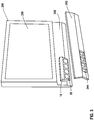
- FIG. 3 illustrates an embodiment in which the carrier unit 10 comprising modules 20 is mounted to the SVDU 200.
- the carrier unit 10 is affixed to a bottom portion 240 of the display unit 200, and a cover 242 having access holes 244 is placed over the bottom portion 240 and the carrier unit 10 in order to provide an aesthetic look and feel.
- the carrier unit 10 is integrated into the SVDU 200.
- the carrier unit 10 could also be located in a part of the passenger's seat, such as in the arm rest or other portion. In such a configuration, it is also possible to provide a cable or tether that connects the carrier unit 10 with the SVDU 200.
- FIG. 4 A further embodiment of the invention is shown in Figure 4 .
- the passenger interface modules 20.x are integrated into a passenger tray table 400.
- the tray table 400 is typically located within a tray storage area 414 to which a display 410 and display arm 412 holding the display may be affixed.
- the upper two images of the tray table 400 show a thin tray design having a broadened end portion 405 that is wide enough to accommodate the modules 20.
- a thick tray design 400a is provided that can accommodate additional electronics, etc.
- Figure 4 shows the modules located in a preferable position on a front part of the tray table, it is possible that they could be located on either side or even on the top surface of the tray.
- the modules 20 when the modules 20 are located on the side surface of the tray 400 (depending on the tray configuration), they can be advantageously accessed even when the tray is in a stowed position. In other configurations for storing the tray 400, the modules 20 can be placed so that they are accessible when the tray 400 is stowed.
- the integration of the modules 20 into the tray table advantageously creates additional space for passengers and respective peripherals, particularly in front-row economy seating (and other space-limited seating) where space is at a premium.
- peripherals no longer protrude into the seat area and are more easily accessible.
- this design also provides access to PSS functions such as attendant call/cancel, volume, channel.
- the system or systems described herein may be implemented on any form of computer or computers and the components may be implemented as dedicated applications or in client-server architectures, including a web-based architecture, and can include functional programs, codes, and code segments.
- Any of the computers may comprise a processor, a memory for storing program data and executing it, a permanent storage such as a disk drive, a communications port for handling communications with external devices, and user interface devices, including a display, keyboard, mouse, etc.
- these software modules may be stored as program instructions or computer readable codes executable on the processor on a computer-readable media such as read-only memory (ROM), random-access memory (RAM), CD-ROMs, magnetic tapes, floppy disks, and optical data storage devices.
- the computer readable recording medium can also be distributed over network coupled computer systems so that the computer readable code is stored and executed in a distributed fashion. This media can be read by the computer, stored in the memory, and executed by the processor.
- the present invention may be described in terms of functional block components and various processing steps. Such functional blocks may be realized by any number of hardware and/or software components configured to perform the specified functions.
- the present invention may employ various integrated circuit components, e.g., memory elements, processing elements, logic elements, look-up tables, and the like, which may carry out a variety of functions under the control of one or more microprocessors or other control devices.
- the elements of the present invention are implemented using software programming or software elements the invention may be implemented with any programming or scripting language such as C, C++, Java, assembler, or the like, with the various algorithms being implemented with any combination of data structures, objects, processes, routines or other programming elements.
- Functional aspects may be implemented in algorithms that execute on one or more processors.
- the present invention could employ any number of conventional techniques for electronics configuration, signal processing and/or control, data processing and the like.
- the words “mechanism” and “element” are used broadly and are not limited to mechanical or physical embodiments, but can include software routines in conjunction with processors, etc.
Landscapes
- Engineering & Computer Science (AREA)
- Aviation & Aerospace Engineering (AREA)
- Mechanical Engineering (AREA)
- Transportation (AREA)
- Fittings On The Vehicle Exterior For Carrying Loads, And Devices For Holding Or Mounting Articles (AREA)
- Two-Way Televisions, Distribution Of Moving Picture Or The Like (AREA)
- Passenger Equipment (AREA)
Description
- The present invention relates to the field of modular user interfaces for computer-based systems used in vehicles, particularly to in-flight entertainment (IFE) systems.
- IFE systems provide passengers with a wide range of entertainment options, from listening to audio, watching video, playing video games, etc.
- Historically, user interfaces for an IFE have been designed with interface elements-headphone jacks, video jacks, and the like-directly mounted within a seating element, such as an armrest or other structural element near the passenger. However, when such an interface element becomes non-functional, it is difficult and costly to replace. Furthermore, as technology advances, and new forms of standardized interfaces evolve, the directly mounted elements cannot be easily upgraded to take advantage of such advances.
-
US 2002/0195523 discloses a seat track mounted passenger interface device. The device includes a base removably coupled to an aircraft seat track. A riser coupled to the base extends generally vertically away from the seat track. An interface head coupled to the distal end of the riser is located adjacent a passenger seat bottom cushion. One or more jacks and/or sockets are disposed within the interface head. Electrical leads interconnect the jacks and/or sockets with a power source. The electrical leads extend from the interface head, through the riser and base, and then through the seat track raceway. -
WO 2008/014352 discloses a mounting system suitable for use with user interface devices and methods for manufacturing and using same. The mounting system can be installed at any suitable location and, once installed, can receive and engage a selected user interface device. The user interface device thereby can select and present viewing content and, when not in use, can be stowed in a manner that does not interfere with the user. Being provided as modular units, a malfunctioning user interface device can be easily removed from the mounting system and replaced with another user interface device, minimizing inconvenience to the user and facilitating repairs - Accordingly, a video display unit for a vehicle, comprising a module carrier unit according to claim is provided.
- Passenger interface modules having a predefined shape and size, and each containing a different interface unit, can be plugged into various sockets of the communication unit. When one of the modules becomes non-functional, or a different configuration is desired, the modules can easily be removed and replaced.
- Although an in-flight entertainment system is described, it should be understood that use of the terms "flight", "aircraft", and the like herein are proxies used for the sake of convenience that apply to and are defined as being associated with broader concepts of "travel" and "vehicle", and the like. Furthermore, the term "entertainment" data is defined broadly as any data that may be of interest to the passenger.
- Various embodiments of the invention are illustrated below in the drawings.
- FIG. 1
- is a pictorial top view diagram illustrating an embodiment of a module carrier unit having inserted modules, and a block schematic diagram illustrating the associated IFE components;
- FIG. 2A
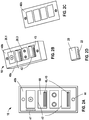
- is a pictorial top view of the communications unit with two of the modules removed, showing the sockets;
- FIG. 2B
- is a perspective view of the communications unit shown in
FIG. 2A ; - FIG. 2C
- is a perspective view of a faceplate that covers the communications unit;
- FIG. 2D
- is a perspective view of a passenger interface module that may be inserted into the communication unit;
- FIG. 3
- is a perspective view of a display having the carrier unit mounted on it; and
- FIG. 4
- is a pictorial perspective view of a further embodiment.
-
FIG. 1 illustrates a system using an exemplary embodiment of amodule carrier unit 10 that connects into anentertainment system - In this system, a
primary server 300 comprises storage that is used to store entertainment-related data, such as multi-media content, programs, such as games, and other related data and programs that might be of interest to a vehicle passenger. - A seat video display unit (SVDU) 200 is located near the seat of the passenger and comprises an interface back to the
server 300 over which entertainment system-related data is transmitted. The SVDU 200 comprises, among other things, aprocessor 210, an I/O adapter 220 for communicating both with thecarrier unit 10 and theserver 300, and adisplay 230, such as an LCD, LED, plasma, touchscreen, or other type of known display. The SVDU 200 contains hardware and software for processing multi-media or other related data. Thecarrier unit 10 may be located in an arm rest, near the display, or any other location that is readily accessible by a seated passenger. - The
carrier unit 10 could be mounted in a cavity of the seating area (not shown) of a size designed to accept theunit 10. The mounting could comprise fasteners, such as screws, bolts, and the like, but could also include various locking mechanisms such as slots and tabs, and the like. - As can be seen in
FIG. 1 , acommunications interface 100 is provided between thecarrier unit 10 and the SVDU 200. Thisinterface 100 can provide two-way communications that includes information such as video data, audio data, user interface control data, game data, etc. In one embodiment, thecommunications interface 100 comprises two USB lines, a video line, an audio line, and a power line that may be used to power thecarrier unit 100. Thecarrier unit 100 connects to the I/O adapter 220 of the SVDU 200. This connection can be either hardwired or could use any connector of a suitable grade. Similarly, the connection to thecarrier unit 10 can be hardwired or use a similar connector. - The
personal carrier unit 10, as shown inFIG. 1 , comprises a number of passenger interface modules (smart Passenger Interface Module-PIM) 20. The exemplary modules shown include an RCA video jack module 20.1, RCA audio left and right jack module 20.2, an audio headphone module 20.3, and a USB module 20.4. Other modules can be envisioned, such as a DIN connector module, a module that permits turning an overhead light on and off, and an attendant call/cancel button. - Referring additionally to
Figures 2A-D , it can be seen that thecarrier unit 10 comprises anouter case 40 made up of abottom portion 40a and afaceplate 40b that can be affixed to thebottom portion 40a with one ormore fasteners 44. Thefaceplate 40b could also be affixed using tabs, slots, and the like, as well. Holes in thefaceplate 40b can be used to help secure themodules 20 into thecarrier unit 10. - The
bottom portion 40a may comprise a group of similarly shaped andsized sockets 42, into which thepassenger interface modules 20 are inserted. Themodules 20 are designed with a common shape and size so that anymodule 20 can plug into anysocket 42. Importantly, a common interface between themodules 20 and thesockets 42 is defined. Themodules 20 may comprise aconnector 22 in the form of pins, electrical contacts, etc. that are designed to mate with corresponding sockets orelectrical contacts 43 that form a bus 45 of thecarrier unit 10. Amodule lock 47 may be provided to help ensure that the modules remain in the socket. Such a lock could be formed, e.g., by a sliding mechanism that slides an interfering surface on top of a surface of the module that prevents its removal from thesocket 42 via an interference fit.Such locks 47 could be placed on both sides of themodule 20, and could be placed adjacent to eachmodule 20. - The
modules 20 themselves are designed to be relatively easy to remove from thesockets 42 and replace. This may involve, e.g., removing thefaceplate 40b, releasing themodule lock 47, or other simple mechanical procedures. However, themodule 20 is preferably not more permanently affixed in thesockets 42 through the use, e.g., of soldered wires, adhesives, and the like. - In a preferred embodiment, the
modules 20 are very simply designed. For example, the audio connectors can be designed simply to pass through the analog audio signal via a simple pair of conductors to corresponding lines on the bus 45 of thecarrier unit 10. Similarly,digital communication modules 20, such as a USB 2.0 connector, can simply pass through the signals directly via connectors to the bus 45. This is consistent with keeping the cost of themodules 20 very inexpensive and easy to replace if they are damaged. Furthermore, with a very simple design, the likelihood of failure is relatively small. - However, it is also possible to have relatively
smart modules 20 used as well. In such a configuration, the modules can comprise electronic circuitry or even processors for handling complex signal processing, such as MP3 conversion to audio signals, video decompression and decoding, wireless communications (e.g., Wi-Fi, Bluetooth), etc. Modules such as a web camera and microphone could also be included. - In a preferred embodiment, the
carrier unit 10 is designed to be of a size to fit in an existing footprint for such controls in present airplanes. Therefore, although any number ofsockets 42 could be provided, a preferred embodiment uses foursockets 42. As can be seen in the example presented above, where the number or size of the interface device, such as the RCA audio/video, makes it impossible to fit on asingle module 20, the interface can be split acrossmultiple modules 20. - The
carrier unit 10 may comprise a printed circuit board (PCB) 60 upon which thesocket connectors 43 are positioned. ThePCB 60 may also comprise a processor, volatile and non-volatile memory, and the I/O adapter 50, as well as other circuitry, such as level shifting circuitry, analog-to-digital (A/D) and digital-to-analog (D/A) converters, and other signal conditioning circuitry to translate signals received from user devices to theSVDU 200, and vice versa. The processor and software may also comprise algorithms for handling various communications protocols that can be utilized both by user devices and for communicating with theSVDU 200. - The module type is automatically determined and the
carrier unit 10 contains circuitry that permits it to accommodate and adapt to the functional needs of themodule 20 that is inserted. - It is further possible to connect a plurality of
carrier units 10 to each other in order to expand the number ofmodules 20 used in the system. In such a configuration, thecommunications bus 100 can be shared between thecarriers 10. This can be the case in which a plurality ofcarrier units 10 are tethered together, where onecarrier unit 10 is (ormultiple carrier units 10 are) mounted, e.g., on theSVDU 200, or in any other mounting or configuration of thecarrier units 10. -
Figure 3 illustrates an embodiment in which thecarrier unit 10 comprisingmodules 20 is mounted to theSVDU 200. In this embodiment, thecarrier unit 10 is affixed to abottom portion 240 of thedisplay unit 200, and acover 242 havingaccess holes 244 is placed over thebottom portion 240 and thecarrier unit 10 in order to provide an aesthetic look and feel. Thus, thecarrier unit 10 is integrated into theSVDU 200. - Although not shown, the
carrier unit 10 could also be located in a part of the passenger's seat, such as in the arm rest or other portion. In such a configuration, it is also possible to provide a cable or tether that connects thecarrier unit 10 with theSVDU 200. - A further embodiment of the invention is shown in
Figure 4 . In this embodiment, the passenger interface modules 20.x are integrated into a passenger tray table 400. The tray table 400 is typically located within atray storage area 414 to which adisplay 410 anddisplay arm 412 holding the display may be affixed. - The upper two images of the tray table 400 show a thin tray design having a broadened
end portion 405 that is wide enough to accommodate themodules 20. In the bottom image, athick tray design 400a is provided that can accommodate additional electronics, etc. - Although
Figure 4 shows the modules located in a preferable position on a front part of the tray table, it is possible that they could be located on either side or even on the top surface of the tray. However, when themodules 20 are located on the side surface of the tray 400 (depending on the tray configuration), they can be advantageously accessed even when the tray is in a stowed position. In other configurations for storing thetray 400, themodules 20 can be placed so that they are accessible when thetray 400 is stowed. - The integration of the
modules 20 into the tray table advantageously creates additional space for passengers and respective peripherals, particularly in front-row economy seating (and other space-limited seating) where space is at a premium. By integrating themodules 20 into the tray table 400, 400a, peripherals no longer protrude into the seat area and are more easily accessible. In addition, this design also provides access to PSS functions such as attendant call/cancel, volume, channel. - The system or systems described herein may be implemented on any form of computer or computers and the components may be implemented as dedicated applications or in client-server architectures, including a web-based architecture, and can include functional programs, codes, and code segments. Any of the computers may comprise a processor, a memory for storing program data and executing it, a permanent storage such as a disk drive, a communications port for handling communications with external devices, and user interface devices, including a display, keyboard, mouse, etc. When software modules are involved, these software modules may be stored as program instructions or computer readable codes executable on the processor on a computer-readable media such as read-only memory (ROM), random-access memory (RAM), CD-ROMs, magnetic tapes, floppy disks, and optical data storage devices. The computer readable recording medium can also be distributed over network coupled computer systems so that the computer readable code is stored and executed in a distributed fashion. This media can be read by the computer, stored in the memory, and executed by the processor.
- All references, including publications, patent applications, and patents, cited herein are hereby incorporated by reference to the same extent as if each reference were individually and specifically indicated to be incorporated by reference and were set forth in its entirety herein.
- For the purposes of promoting an understanding of the principles of the invention, reference has been made to the preferred embodiments illustrated in the drawings, and specific language has been used to describe these embodiments. However, no limitation of the scope of the invention is intended by this specific language, and the invention should be construed to encompass all embodiments that would normally occur to one of ordinary skill in the art.
- The present invention may be described in terms of functional block components and various processing steps. Such functional blocks may be realized by any number of hardware and/or software components configured to perform the specified functions. For example, the present invention may employ various integrated circuit components, e.g., memory elements, processing elements, logic elements, look-up tables, and the like, which may carry out a variety of functions under the control of one or more microprocessors or other control devices. Similarly, where the elements of the present invention are implemented using software programming or software elements the invention may be implemented with any programming or scripting language such as C, C++, Java, assembler, or the like, with the various algorithms being implemented with any combination of data structures, objects, processes, routines or other programming elements. Functional aspects may be implemented in algorithms that execute on one or more processors. Furthermore, the present invention could employ any number of conventional techniques for electronics configuration, signal processing and/or control, data processing and the like. The words "mechanism" and "element" are used broadly and are not limited to mechanical or physical embodiments, but can include software routines in conjunction with processors, etc.
- The particular implementations shown and described herein are illustrative examples of the invention and are not intended to otherwise limit the scope of the invention in any way. For the sake of brevity, conventional electronics, control systems, software development and other functional aspects of the systems (and components of the individual operating components of the systems) may not be described in detail. Furthermore, the connecting lines, or connectors shown in the various figures presented are intended to represent exemplary functional relationships and/or physical or logical couplings between the various elements. It should be noted that many alternative or additional functional relationships, physical connections or logical connections may be present in a practical device. Moreover, no item or component is essential to the practice of the invention unless the element is specifically described as "essential" or "critical".
- The use of "including," "comprising," or "having" and variations thereof herein is meant to encompass the items listed thereafter and equivalents thereof as well as additional items. Unless specified or limited otherwise, the terms "mounted," "connected," "supported," and "coupled" and variations thereof are used broadly and encompass both direct and indirect mountings, connections, supports, and couplings. Further, "connected" and "coupled" are not restricted to physical or mechanical connections or couplings.
- The use of the terms "a" and "an" and "the" and similar referents in the context of describing the invention (especially in the context of the following claims) are to be construed to cover both the singular and the plural. Furthermore, recitation of ranges of values herein are merely intended to serve as a shorthand method of referring individually to each separate value falling within the range, unless otherwise indicated herein, and each separate value is incorporated into the specification as if it were individually recited herein. Finally, the steps of all methods described herein can be performed in any suitable order unless otherwise indicated herein or otherwise clearly contradicted by context. The use of any and all examples, or exemplary language (e.g., "such as") provided herein, is intended merely to better illuminate the invention and does not pose a limitation on the scope of the invention unless otherwise claimed. Numerous modifications and adaptations will be readily apparent to those skilled in this art without departing from the scope of the appended claims.
-
- 10
- (module) carrier unit, integrated vehicle passenger interface and communication unit
- 20, 20.x
- passenger interface module, connector insert
- 22
- module connector
- 40
- outer case
- 40a
- outer case bottom portion
- 40b
- outer case faceplate
- 42
- socket, hole
- 43
- socket connector
- 44
- outer case fastener
- 45
- interface unit bus
- 47
- module lock
- 50
- I/O adapter
- 60
- interface unit PCB
- 100
- communications interface
- 200
- seat video display unit
- 210
- processor, passenger proximate processor, processor board
- 220
- SVDU I/O adapter
- 230
- display, screen
- 240
- display bottom portion
- 242
- display cover
- 244
- display cover holes
- 300
- in-flight entertainment system server
- 400
- tray table
- 405
- broadened end portion
- 410
- display
- 412
- display arm
- 414
- tray storage area
Claims (13)
- A video display unit (200) for a vehicle, comprising a module carrier unit (10) directly affixed to a portion of the video display unit (200), comprising:a plurality of passenger interface modules (20) that perform different functions, the functions including at least one of inputting signals from one or more user devices and outputting signals to one or more user devices, the modules (20) having a common size and shape, and a common electrical connector (22);an outer case portion (40) comprising a plurality of recessed sockets (42), each having a common size and shape, and a common electrical connector (43),the plurality of sockets (42) being configured so that any one of passenger interface modules (20) having the different functions is connected to any one of the sockets (42) to electrically mate the electrical connector (22) of the one of the passenger interface modules (20) to the electrical connector (42) of the one of the sockets (42);a communications interface (100) connected to a processor (210) located near a seat of a passenger in the vehicle; anda cover panel (242) having holes (244)in it, the cover panel being affixed to a portion (240) of the video display unit (200) and covering the module carrier unit (10) while providing access to the passenger interface modules (20) through the holes.
- The video display unit (200) according to claim 1, wherein:
the passenger interface modules (20) are selected from the group consisting of a USB port (20.4), a DIN audio port, a headphone jack (20.3), an RCA video jack (20.1), RCA stereo audio jacks (20.2), and an attendant call button. - The video display unit (200) according to claim 1, wherein the outer case portion (40) is generally rectangular in shape.
- The video display unit (200) according to claim 1, wherein while the video display unit (200) is upright the module carrier unit (10) is directly affixed to the video display unit (200) below a display (230).
- The video display unit (200) according to claim 1, further comprising:
a printed circuit board (PCB) (60) comprising socket connectors (43) that form a bus (45), which socket connectors (43) mate with the electrical connectors (22) of the passenger interface modules (20). - The video display unit (200) according to claim 5, wherein the PCB (60) comprises:a processor that processes signals sent to the one or more user devices through one or more of the passenger interface modules (20) or that processes signals received from the one or more of the user devices through one or more of the passenger interface modules (20); anda memory used by the processor during processing.
- The video display unit (200) according to claim 6, further comprising:
a communication protocol algorithm stored in the memory that when executed by the processor causes the processor to interface with the one or more user devices through one or more of the passenger interface modules (20). - The video display unit (200) according to claim 1, further comprising:
hardware that performs multiplexed communication between the passenger interface modules (20) and the processor (210) through the communication interface. - The video display unit (200) according to claim 5, wherein the PCB (60) comprises:
electrical signal level shifting circuitry that translates signals received from or provided to a user device connected to one of the passenger interface modules (20) connected to one of the sockets (42) of the module carrier unit (10). - The video display unit (200) according to claim 5, wherein the PCB (60) comprises an analog-to-digital converter that translates signals received from or provided to a user device connected to one of the passenger interface modules (20) connected to one of the sockets (42) of the module carrier unit (10).
- The video display unit (200) according to claim 5, wherein the PCB (60) comprises a digital-to-analog converter that translates signals received from or provided to a user device connected to one of the passenger interface modules (20) connected to one of the sockets (42) of the module carrier unit (10).
- The video display unit (200) according to claim 1, further comprising circuitry configured to accommodate and adapt to a functional need of one of the passenger interface modules (20) connected to one of the sockets (42) of the module carrier unit (10).
- The video display unit (200) according to claim 1, wherein the cover panel (242) retains the passenger interface modules (20) within the sockets (42) while covering the module carrier unit (10).
Applications Claiming Priority (2)
| Application Number | Priority Date | Filing Date | Title |
|---|---|---|---|
| US34528610P | 2010-05-17 | 2010-05-17 | |
| PCT/US2011/036741 WO2011146429A1 (en) | 2010-05-17 | 2011-05-17 | Airline passenger seat modular user interface device |
Publications (3)
| Publication Number | Publication Date |
|---|---|
| EP2572408A1 EP2572408A1 (en) | 2013-03-27 |
| EP2572408A4 EP2572408A4 (en) | 2017-03-29 |
| EP2572408B1 true EP2572408B1 (en) | 2021-07-07 |
Family
ID=44992012
Family Applications (1)
| Application Number | Title | Priority Date | Filing Date |
|---|---|---|---|
| EP11784060.3A Active EP2572408B1 (en) | 2010-05-17 | 2011-05-17 | Airline passenger seat modular user interface device |
Country Status (5)
| Country | Link |
|---|---|
| US (1) | US8929082B2 (en) |
| EP (1) | EP2572408B1 (en) |
| CN (1) | CN102939691B (en) |
| BR (1) | BR112012028245B1 (en) |
| WO (1) | WO2011146429A1 (en) |
Families Citing this family (25)
| Publication number | Priority date | Publication date | Assignee | Title |
|---|---|---|---|---|
| GB201121409D0 (en) * | 2011-12-13 | 2012-01-25 | Ifpl Group Ltd | User control interface |
| GB201205275D0 (en) * | 2012-03-26 | 2012-05-09 | Soundchip Sa | Media/communications system |
| WO2014130973A1 (en) | 2013-02-22 | 2014-08-28 | Greig, Nigel | Converter jack |
| CA151587S (en) | 2013-06-10 | 2015-11-30 | Inflight Invest Inc | Aircraft passenger control unit with electric power outlet |
| CN103581692A (en) * | 2013-11-05 | 2014-02-12 | 成都金本华科技股份有限公司 | Airborne entertainment system based on combination of streaming media unicast and multicast and unicast control method thereof |
| US9487134B2 (en) | 2015-03-04 | 2016-11-08 | Panasonic Avionics Corporation | Seat back illumination module |
| US9420314B1 (en) * | 2015-05-07 | 2016-08-16 | The Boeing Company | Distribution of in-flight entertainment content to portable electronic devices |
| CA3005395C (en) * | 2015-11-23 | 2023-04-18 | Bombardier Inc. | System and a method of operation of the system incorporating a graphical user interface in a bulkhead of a vehicle cabin |
| EP3229475A1 (en) * | 2016-04-04 | 2017-10-11 | Nigel Greig | Ife system |
| CN106218453B (en) * | 2016-08-18 | 2019-05-10 | 安路普(北京)汽车技术有限公司 | A kind of control system and gas suspension seat of gas suspension seat |
| GB201712310D0 (en) * | 2017-07-31 | 2017-09-13 | Ifpl Group Ltd | Passenger vehicle interface system |
| WO2019043992A1 (en) | 2017-09-04 | 2019-03-07 | パナソニックIpマネジメント株式会社 | Electronic apparatus |
| US11424816B2 (en) | 2018-05-15 | 2022-08-23 | Pratt & Whitney Canada Corp. | Communication module for transmission of aircraft data |
| DE102018133176A1 (en) * | 2018-12-20 | 2020-06-25 | Airbus Operations Gmbh | Electrical adapter, aircraft display system and aircraft |
| US11208211B2 (en) * | 2019-04-26 | 2021-12-28 | Burrana Ip And Assets, Llc | Replaceable connection modules for high use electronic device receptacles |
| CN111169409B (en) * | 2020-02-21 | 2022-03-18 | 广州小鹏汽车科技有限公司 | Control method and vehicle |
| JP7242723B2 (en) * | 2021-01-29 | 2023-03-20 | 本田技研工業株式会社 | vehicle seat |
| JP7157834B2 (en) * | 2021-01-29 | 2022-10-20 | 本田技研工業株式会社 | vehicle seat |
| US12073205B2 (en) | 2021-09-14 | 2024-08-27 | Targus International Llc | Independently upgradeable docking stations |
| US20230125019A1 (en) * | 2021-10-19 | 2023-04-20 | Kien Hoe Daniel Chin | Advanced hub apparatus for mobile computer |
| CN114498218B (en) * | 2022-03-02 | 2024-04-09 | 沈阳旭阳中冶座椅有限公司 | High-speed railway table top with socket |
| USD1066291S1 (en) | 2022-05-12 | 2025-03-11 | Panasonic Avionics Corporation | Display system |
| US12012222B2 (en) | 2022-05-12 | 2024-06-18 | Panasonic Avionics Corporation | Programmable lighting methods and systems for a removable peripheral bar |
| US12208899B2 (en) | 2022-05-12 | 2025-01-28 | Panasonic Avionics Corporation | Display systems with a modular peripheral bar assembly and associated methods thereof |
| US11607957B1 (en) * | 2022-05-12 | 2023-03-21 | Panasonic Avionics Corporation | Accent lighting based display systems and associated methods thereof |
Family Cites Families (124)
| Publication number | Priority date | Publication date | Assignee | Title |
|---|---|---|---|---|
| US1368307A (en) | 1918-04-13 | 1921-02-15 | Western Electric Co | Earpiece |
| US1498727A (en) | 1923-04-07 | 1924-06-24 | Haskel Fred | Removable ear-cushion for telephones |
| US1514152A (en) | 1923-12-28 | 1924-11-04 | Gernsback Hugo | Ear cushion |
| US1586140A (en) | 1924-12-09 | 1926-05-25 | Ralph W S Bonnette | Receiver for radio and telephone apparatus |
| US1807225A (en) | 1928-03-09 | 1931-05-26 | Utah Radio Products Company In | Sound propagating diaphragm |
| US2346395A (en) | 1942-05-04 | 1944-04-11 | Rca Corp | Sound pickup device |
| US2379891A (en) | 1942-10-06 | 1945-07-10 | Bell Telephone Labor Inc | Sound translating device |
| US2427844A (en) | 1942-12-16 | 1947-09-23 | Gylling & Co Ab | Vibratory unit for electrodynamic loud-speakers |
| US2490466A (en) | 1944-07-19 | 1949-12-06 | Rca Corp | Loudspeaker diaphragm support comprising plural compliant members |
| US2603724A (en) | 1948-10-30 | 1952-07-15 | Rca Corp | Sound translating device arranged to eliminate extraneous sound |
| US2622159A (en) | 1950-03-11 | 1952-12-16 | Sydney K Herman | Ear pad for earpieces |
| US2714134A (en) | 1951-02-27 | 1955-07-26 | Martin L Touger | Headset receiver |
| US2761912A (en) | 1951-05-31 | 1956-09-04 | Martin L Touger | Sound translating apparatus |
| US2972018A (en) | 1953-11-30 | 1961-02-14 | Rca Corp | Noise reduction system |
| US2775309A (en) | 1954-03-15 | 1956-12-25 | Acoustic Res Inc | Sound translating devices |
| US2848560A (en) | 1954-09-20 | 1958-08-19 | Beltone Hearing Aid Company | Hearing aid receiver |
| USRE26030E (en) | 1956-02-28 | 1966-05-24 | Dynamic transducer | |
| US3112005A (en) | 1960-07-28 | 1963-11-26 | Ca Nat Research Council | Earphones |
| NL257376A (en) | 1959-10-29 | |||
| US2989598A (en) | 1960-02-24 | 1961-06-20 | Martin L Touger | Hard shell liquid seal earmuff with isolated inner close coupling ear shell |
| US3367040A (en) | 1964-06-05 | 1968-02-06 | A J Ind Inc | Automobile drier unit with muffler means and selectively operable air diverting means |
| US3403235A (en) | 1965-03-17 | 1968-09-24 | Newmarkets Inc | Wide-range loudspeaker |
| US3727004A (en) | 1967-12-04 | 1973-04-10 | Bose Corp | Loudspeaker system |
| US3532837A (en) | 1967-12-19 | 1970-10-06 | Ibm | Headset featuring collapsibility for storage |
| US3602329A (en) | 1970-01-07 | 1971-08-31 | Columbia Broadcasting Systems | Conformal ear enclosure |
| US3644939A (en) | 1970-10-12 | 1972-02-29 | American Optical Corp | Air damped hearing protector earseal |
| US3766332A (en) | 1971-05-17 | 1973-10-16 | Industrial Res Prod Inc | Electroacoustic transducer |
| SE377025B (en) | 1972-01-10 | 1975-06-16 | Northern Electric Co | |
| DE2329851C2 (en) | 1973-06-12 | 1975-08-14 | Neckermann Versand Kgaa, 6000 Frankfurt | Headphones for the playback of real quadrophonically recorded information |
| US4005267A (en) | 1974-05-17 | 1977-01-25 | Akg Akustische U. Kino-Gerate Gesellschaft M.B.H. | Arrangement for converting oscillations in headphones |
| CA1032479A (en) | 1974-09-16 | 1978-06-06 | Rudolf Gorike | Headphone |
| JPS5162819U (en) | 1974-11-13 | 1976-05-18 | ||
| DE2461278B2 (en) | 1974-12-23 | 1976-12-16 | Foster Electric Co., Ltd., Tokio | ELECTROACOUSTIC CONVERTER |
| US4006318A (en) | 1975-04-21 | 1977-02-01 | Dyna Magnetic Devices, Inc. | Inertial microphone system |
| JPS51129217A (en) | 1975-05-06 | 1976-11-10 | Victor Co Of Japan Ltd | Headphone |
| US4058688A (en) | 1975-05-27 | 1977-11-15 | Matsushita Electric Industrial Co., Ltd. | Headphone |
| AT355646B (en) | 1977-02-02 | 1980-03-10 | Akg Akustische Kino Geraete | HEADPHONES FOR IMPROVED SPATIAL HEARINGS |
| US4211898A (en) | 1977-07-11 | 1980-07-08 | Matsushita Electric Industrial Co., Ltd. | Headphone with two resonant peaks for simulating loudspeaker reproduction |
| US4156118A (en) | 1978-04-10 | 1979-05-22 | Hargrave Frances E | Audiometric headset |
| AT361555B (en) | 1979-02-12 | 1981-03-25 | Akg Akustische Kino Geraete | HEADPHONE |
| US4297537A (en) | 1979-07-16 | 1981-10-27 | Babb Burton A | Dynamic loudspeaker |
| US4581496A (en) | 1979-09-04 | 1986-04-08 | Emhart Industries, Inc. | Diaphragm for attenuating harmonic response in an electroacoustic transducer |
| US4347405A (en) | 1979-09-06 | 1982-08-31 | Cbs Inc. | Sound reproducing systems utilizing acoustic processing unit |
| JPS6042558Y2 (en) | 1980-04-17 | 1985-12-27 | ソニー株式会社 | speaker |
| GB2082020B (en) | 1980-06-30 | 1985-05-30 | Pioneer Electronic Corp | Ear speaker |
| ZA825676B (en) | 1981-08-11 | 1983-06-29 | Sound Attenuators Ltd | Method and apparatus for low frequency active attennuation |
| US4528689A (en) | 1981-09-22 | 1985-07-09 | International Acoustics Incorporated | Sound monitoring apparatus |
| US4418248A (en) | 1981-12-11 | 1983-11-29 | Koss Corporation | Dual element headphone |
| US4441576A (en) | 1982-04-19 | 1984-04-10 | Allen Clayton H | Nonlinear passive acoustic filtering |
| US4455675A (en) | 1982-04-28 | 1984-06-19 | Bose Corporation | Headphoning |
| US4494074A (en) | 1982-04-28 | 1985-01-15 | Bose Corporation | Feedback control |
| AT377664B (en) | 1983-05-26 | 1985-04-25 | Akg Akustische Kino Geraete | EAR CUSHION |
| DE3512405A1 (en) | 1984-04-06 | 1985-10-31 | Bose Corp., Framingham, Mass. | Circuit arrangement for generating an output signal controlled by a supplied input signal, and headphones |
| US4592366A (en) | 1984-04-16 | 1986-06-03 | Matsushita Electric Works, Ltd. | Automated blood pressure monitoring instrument |
| US4529058A (en) | 1984-09-17 | 1985-07-16 | Emery Earl L | Earphones |
| JPH0733508Y2 (en) | 1984-10-31 | 1995-07-31 | ソニー株式会社 | earphone |
| GB2172470B (en) | 1985-03-16 | 1989-01-11 | Plessey Co Plc | Improvement relating to noise reduction arrangements |
| GB8506860D0 (en) | 1985-03-16 | 1985-04-17 | Plessey Co Plc | Noise reduction arrangements |
| US4644581A (en) | 1985-06-27 | 1987-02-17 | Bose Corporation | Headphone with sound pressure sensing means |
| US4670733A (en) | 1985-07-01 | 1987-06-02 | Bell Microsensors, Inc. | Differential pressure transducer |
| AT383930B (en) | 1985-11-18 | 1987-09-10 | Akg Akustische Kino Geraete | EAR PADS FOR HEADPHONES |
| JPH0450718Y2 (en) | 1986-02-28 | 1992-11-30 | ||
| GB8607047D0 (en) | 1986-03-21 | 1986-04-30 | Univ Southampton | Acoustic noise reduction |
| US4669129A (en) | 1986-04-07 | 1987-06-02 | Chance Richard L | Earmuff apparatus for use with headsets |
| US4852177A (en) | 1986-08-28 | 1989-07-25 | Sensesonics, Inc. | High fidelity earphone and hearing aid |
| NL8602451A (en) | 1986-09-29 | 1988-04-18 | Philips Nv | SPEAKER WITH A TWO-PIECE MEMBRANE FOR USE AS A CAR SPEAKER. |
| NZ225001A (en) | 1987-06-16 | 1990-09-26 | Matsushita Electric Industrial Co Ltd | Loudspeaker: reflected sound waves absorbed |
| US4922542A (en) | 1987-12-28 | 1990-05-01 | Roman Sapiejewski | Headphone comfort |
| US5181252A (en) | 1987-12-28 | 1993-01-19 | Bose Corporation | High compliance headphone driving |
| US4905322A (en) | 1988-04-18 | 1990-03-06 | Gentex Corporation | Energy-absorbing earcup assembly |
| US4985925A (en) | 1988-06-24 | 1991-01-15 | Sensor Electronics, Inc. | Active noise reduction system |
| US4949806A (en) | 1988-12-20 | 1990-08-21 | Stanton Magnetics, Inc. | Headset for underwater use |
| US5020163A (en) | 1989-06-29 | 1991-06-04 | Gentex Corporation | Earseal for sound-attenuating earcup assembly |
| GB2234882B (en) | 1989-08-03 | 1994-01-12 | Plessey Co Plc | Noise reduction system |
| US5134659A (en) | 1990-07-10 | 1992-07-28 | Mnc, Inc. | Method and apparatus for performing noise cancelling and headphoning |
| US5001763A (en) | 1989-08-10 | 1991-03-19 | Mnc Inc. | Electroacoustic device for hearing needs including noise cancellation |
| US5117461A (en) | 1989-08-10 | 1992-05-26 | Mnc, Inc. | Electroacoustic device for hearing needs including noise cancellation |
| CA2023142A1 (en) | 1989-08-23 | 1991-02-24 | Roman Sapiejewski | High compliance headphone driving |
| US4989271A (en) | 1989-08-24 | 1991-02-05 | Bose Corporation | Headphone cushioning |
| US5305387A (en) | 1989-10-27 | 1994-04-19 | Bose Corporation | Earphoning |
| GB9003938D0 (en) | 1990-02-21 | 1990-04-18 | Ross Colin F | Noise reducing system |
| US5182774A (en) | 1990-07-20 | 1993-01-26 | Telex Communications, Inc. | Noise cancellation headset |
| JPH06503897A (en) | 1990-09-14 | 1994-04-28 | トッドター、クリス | Noise cancellation system |
| US5208868A (en) | 1991-03-06 | 1993-05-04 | Bose Corporation | Headphone overpressure and click reducing |
| JP2814772B2 (en) | 1991-05-16 | 1998-10-27 | ソニー株式会社 | Earbud headphones |
| US5267321A (en) | 1991-11-19 | 1993-11-30 | Edwin Langberg | Active sound absorber |
| US5640302A (en) * | 1992-06-29 | 1997-06-17 | Elonex Ip Holdings | Modular portable computer |
| US5343523A (en) | 1992-08-03 | 1994-08-30 | At&T Bell Laboratories | Telephone headset structure for reducing ambient noise |
| US5732143A (en) | 1992-10-29 | 1998-03-24 | Andrea Electronics Corp. | Noise cancellation apparatus |
| US7103188B1 (en) | 1993-06-23 | 2006-09-05 | Owen Jones | Variable gain active noise cancelling system with improved residual noise sensing |
| EP0967592B1 (en) | 1993-06-23 | 2007-01-24 | Noise Cancellation Technologies, Inc. | Variable gain active noise cancellation system with improved residual noise sensing |
| WO1995008907A1 (en) | 1993-09-20 | 1995-03-30 | Noise Cancellation Technologies, Inc. | Optimum headset and method of adjusting same |
| CN1050962C (en) | 1993-09-29 | 2000-03-29 | 黄大伟 | Anti-noise earphone |
| US5497426A (en) | 1993-11-15 | 1996-03-05 | Jay; Gregory D. | Stethoscopic system for high-noise environments |
| US5504281A (en) | 1994-01-21 | 1996-04-02 | Minnesota Mining And Manufacturing Company | Perforated acoustical attenuators |
| US5652799A (en) | 1994-06-06 | 1997-07-29 | Noise Cancellation Technologies, Inc. | Noise reducing system |
| US6567525B1 (en) | 1994-06-17 | 2003-05-20 | Bose Corporation | Supra aural active noise reduction headphones |
| SE505203C2 (en) | 1995-02-01 | 1997-07-14 | Bilsom Ab | A method for changing the sound attenuation of an earmuff as well as the earmuff according to the method |
| US5675658A (en) | 1995-07-27 | 1997-10-07 | Brittain; Thomas Paige | Active noise reduction headset |
| US6163615A (en) | 1997-08-06 | 2000-12-19 | University Research & Engineers & Associates, Inc. | Circumaural ear cup audio seal for use in connection with a headset, ear defender, helmet and the like |
| SE507884C2 (en) | 1996-05-03 | 1998-07-27 | Ericsson Telefon Ab L M | Device and method for sound recording in a speech communicator |
| US5740257A (en) | 1996-12-19 | 1998-04-14 | Lucent Technologies Inc. | Active noise control earpiece being compatible with magnetic coupled hearing aids |
| US20010050993A1 (en) | 1997-03-19 | 2001-12-13 | Andrea Douglas | Active noise reduction apparatus having a headset with dual stereo jacks and an electronic device having switch means |
| CN1190993C (en) | 1997-04-17 | 2005-02-23 | 伯斯有限公司 | Acoustic noise reducing |
| US6278786B1 (en) | 1997-07-29 | 2001-08-21 | Telex Communications, Inc. | Active noise cancellation aircraft headset system |
| CN1087243C (en) | 1997-10-07 | 2002-07-10 | 财团法人工业技术研究院 | Car anti-theft system using FM subcarrier radio data system and differential global positioning system |
| CN2311860Y (en) * | 1997-10-10 | 1999-03-24 | 周时敏 | Building block type source junction box |
| US6326973B1 (en) | 1998-12-07 | 2001-12-04 | Compaq Computer Corporation | Method and system for allocating AGP/GART memory from the local AGP memory controller in a highly parallel system architecture (HPSA) |
| US6597792B1 (en) | 1999-07-15 | 2003-07-22 | Bose Corporation | Headset noise reducing |
| US6601798B2 (en) * | 2001-06-26 | 2003-08-05 | The Boeing Company | Seat track mounted passenger interface |
| US6665189B1 (en) * | 2002-07-18 | 2003-12-16 | Rockwell Collins, Inc. | Modular electronics system package |
| WO2004055949A1 (en) | 2002-12-18 | 2004-07-01 | Pirelli & C. S.P.A. | Modular apparatus and method for data communication between a distribution network and a residential network |
| US7445507B1 (en) | 2003-12-19 | 2008-11-04 | Nortel Networks Limited | Connector module with embedded physical layer support and method |
| EP1749404A4 (en) * | 2004-05-27 | 2010-12-22 | Thales Avionics Inc | System for delivering multimedia content to airline passengers |
| US20060258226A1 (en) | 2005-05-12 | 2006-11-16 | Henry Milan | Interchangeable Cover Power Strip |
| US8166506B2 (en) * | 2005-09-12 | 2012-04-24 | The Boeing Company | Simplified cabin services system for an aircraft |
| US7248705B1 (en) | 2005-12-29 | 2007-07-24 | Van Hauser Llc | Noise reducing headphones with sound conditioning |
| WO2008013729A2 (en) * | 2006-07-21 | 2008-01-31 | Thales Avionics, Inc. | Aircraft video display unit and system |
| WO2008014352A1 (en) | 2006-07-25 | 2008-01-31 | Panasonic Avionics Corporation | System and method for mounting user interface devices |
| TWM337156U (en) | 2008-01-11 | 2008-07-21 | Micro Star Int Co Ltd | Composite input/output port electric connector |
| US20090288123A1 (en) * | 2008-05-14 | 2009-11-19 | Havlovick Ron G | Passenger tray convenience system |
| US8145821B2 (en) * | 2008-05-20 | 2012-03-27 | Honeywell International Inc. | Docking station for portable electronic devices |
| JP4936197B2 (en) * | 2008-08-26 | 2012-05-23 | パナソニック株式会社 | Wiring device |
| EP2226902A3 (en) * | 2009-03-06 | 2013-03-13 | Phitek Systems Limited | In-flight entertainment system connector |
-
2011
- 2011-05-17 CN CN201180024304.6A patent/CN102939691B/en active Active
- 2011-05-17 BR BR112012028245-0A patent/BR112012028245B1/en active IP Right Grant
- 2011-05-17 WO PCT/US2011/036741 patent/WO2011146429A1/en not_active Ceased
- 2011-05-17 EP EP11784060.3A patent/EP2572408B1/en active Active
- 2011-05-17 US US13/109,143 patent/US8929082B2/en active Active
Non-Patent Citations (1)
| Title |
|---|
| None * |
Also Published As
| Publication number | Publication date |
|---|---|
| US8929082B2 (en) | 2015-01-06 |
| CN102939691B (en) | 2015-08-05 |
| BR112012028245B1 (en) | 2021-04-20 |
| CN102939691A (en) | 2013-02-20 |
| BR112012028245A2 (en) | 2016-08-02 |
| WO2011146429A1 (en) | 2011-11-24 |
| EP2572408A4 (en) | 2017-03-29 |
| US20120039048A1 (en) | 2012-02-16 |
| EP2572408A1 (en) | 2013-03-27 |
Similar Documents
| Publication | Publication Date | Title |
|---|---|---|
| US8929082B2 (en) | Airline passenger seat modular user interface device | |
| US12050494B2 (en) | Desktop electronic device | |
| EP2226902A2 (en) | In-flight entertainment system connector | |
| US10863644B1 (en) | Double-layer compute sled and cam mounting mechanism | |
| JP5544018B2 (en) | System and method for providing an integrated user interface system to a seat | |
| US20150227277A1 (en) | System and method for providing an integrated user interface system at a seat | |
| EP3005019B1 (en) | Computer internal architecture | |
| US7099152B2 (en) | Computer system with configurable docking station | |
| EP2917106B1 (en) | Personal electronic device mounting assemblies | |
| US8819745B2 (en) | Media device interface system and method for vehicle information systems | |
| US10816943B2 (en) | User control interface | |
| US20230364993A1 (en) | Display systems and associated methods thereof | |
| CN101861563A (en) | Portable user control device and method for vehicle information system | |
| US20100138581A1 (en) | Universal Docking System | |
| WO2009036362A1 (en) | System and method for interfacing a portable media device with a vehicle information system | |
| WO2011140039A1 (en) | Video desplay with detachable input/ output console | |
| US11042189B2 (en) | Docking cradle for a handheld computing device having multiple mounting orientations | |
| US9407034B2 (en) | Communication connector system and method | |
| US12528598B2 (en) | Programmable lighting methods and systems for a removable peripheral bar | |
| US20120250879A1 (en) | Media and communication system | |
| US20230365259A1 (en) | Display systems with a modular peripheral bar assembly and associated methods thereof | |
| US11072428B2 (en) | Reconfigurable modular in-vehicle entertainment monitor systems | |
| US20090190297A1 (en) | Motherboard expansion device | |
| JP2016129219A (en) | Electronic assembly including multiple electronic packages | |
| US20140153178A1 (en) | Secure Housing for a Portable Computer |
Legal Events
| Date | Code | Title | Description |
|---|---|---|---|
| PUAI | Public reference made under article 153(3) epc to a published international application that has entered the european phase |
Free format text: ORIGINAL CODE: 0009012 |
|
| 17P | Request for examination filed |
Effective date: 20121210 |
|
| AK | Designated contracting states |
Kind code of ref document: A1 Designated state(s): AL AT BE BG CH CY CZ DE DK EE ES FI FR GB GR HR HU IE IS IT LI LT LU LV MC MK MT NL NO PL PT RO RS SE SI SK SM TR |
|
| DAX | Request for extension of the european patent (deleted) | ||
| RA4 | Supplementary search report drawn up and despatched (corrected) |
Effective date: 20170228 |
|
| RIC1 | Information provided on ipc code assigned before grant |
Ipc: B60R 11/00 20060101ALI20170222BHEP Ipc: B60N 2/02 20060101ALI20170222BHEP Ipc: B60R 11/02 20060101ALI20170222BHEP Ipc: B60N 2/48 20060101AFI20170222BHEP Ipc: B64D 11/06 20060101ALI20170222BHEP Ipc: B64D 11/00 20060101ALI20170222BHEP |
|
| STAA | Information on the status of an ep patent application or granted ep patent |
Free format text: STATUS: EXAMINATION IS IN PROGRESS |
|
| 17Q | First examination report despatched |
Effective date: 20200511 |
|
| REG | Reference to a national code |
Ref country code: DE Ref legal event code: R079 Ref document number: 602011071329 Country of ref document: DE Free format text: PREVIOUS MAIN CLASS: H01R0013600000 Ipc: B60R0011020000 |
|
| RIC1 | Information provided on ipc code assigned before grant |
Ipc: B64D 11/00 20060101ALI20201123BHEP Ipc: B60R 11/02 20060101AFI20201123BHEP Ipc: B60R 11/00 20060101ALI20201123BHEP Ipc: B60N 2/02 20060101ALI20201123BHEP Ipc: B64D 11/06 20060101ALI20201123BHEP |
|
| GRAP | Despatch of communication of intention to grant a patent |
Free format text: ORIGINAL CODE: EPIDOSNIGR1 |
|
| STAA | Information on the status of an ep patent application or granted ep patent |
Free format text: STATUS: GRANT OF PATENT IS INTENDED |
|
| INTG | Intention to grant announced |
Effective date: 20210114 |
|
| GRAS | Grant fee paid |
Free format text: ORIGINAL CODE: EPIDOSNIGR3 |
|
| GRAA | (expected) grant |
Free format text: ORIGINAL CODE: 0009210 |
|
| STAA | Information on the status of an ep patent application or granted ep patent |
Free format text: STATUS: THE PATENT HAS BEEN GRANTED |
|
| AK | Designated contracting states |
Kind code of ref document: B1 Designated state(s): AL AT BE BG CH CY CZ DE DK EE ES FI FR GB GR HR HU IE IS IT LI LT LU LV MC MK MT NL NO PL PT RO RS SE SI SK SM TR |
|
| REG | Reference to a national code |
Ref country code: GB Ref legal event code: FG4D |
|
| REG | Reference to a national code |
Ref country code: AT Ref legal event code: REF Ref document number: 1408264 Country of ref document: AT Kind code of ref document: T Effective date: 20210715 |
|
| REG | Reference to a national code |
Ref country code: DE Ref legal event code: R096 Ref document number: 602011071329 Country of ref document: DE |
|
| REG | Reference to a national code |
Ref country code: IE Ref legal event code: FG4D |
|
| REG | Reference to a national code |
Ref country code: LT Ref legal event code: MG9D |
|
| REG | Reference to a national code |
Ref country code: NL Ref legal event code: MP Effective date: 20210707 |
|
| REG | Reference to a national code |
Ref country code: AT Ref legal event code: MK05 Ref document number: 1408264 Country of ref document: AT Kind code of ref document: T Effective date: 20210707 |
|
| PG25 | Lapsed in a contracting state [announced via postgrant information from national office to epo] |
Ref country code: HR Free format text: LAPSE BECAUSE OF FAILURE TO SUBMIT A TRANSLATION OF THE DESCRIPTION OR TO PAY THE FEE WITHIN THE PRESCRIBED TIME-LIMIT Effective date: 20210707 Ref country code: SE Free format text: LAPSE BECAUSE OF FAILURE TO SUBMIT A TRANSLATION OF THE DESCRIPTION OR TO PAY THE FEE WITHIN THE PRESCRIBED TIME-LIMIT Effective date: 20210707 Ref country code: NO Free format text: LAPSE BECAUSE OF FAILURE TO SUBMIT A TRANSLATION OF THE DESCRIPTION OR TO PAY THE FEE WITHIN THE PRESCRIBED TIME-LIMIT Effective date: 20211007 Ref country code: PT Free format text: LAPSE BECAUSE OF FAILURE TO SUBMIT A TRANSLATION OF THE DESCRIPTION OR TO PAY THE FEE WITHIN THE PRESCRIBED TIME-LIMIT Effective date: 20211108 Ref country code: NL Free format text: LAPSE BECAUSE OF FAILURE TO SUBMIT A TRANSLATION OF THE DESCRIPTION OR TO PAY THE FEE WITHIN THE PRESCRIBED TIME-LIMIT Effective date: 20210707 Ref country code: RS Free format text: LAPSE BECAUSE OF FAILURE TO SUBMIT A TRANSLATION OF THE DESCRIPTION OR TO PAY THE FEE WITHIN THE PRESCRIBED TIME-LIMIT Effective date: 20210707 Ref country code: ES Free format text: LAPSE BECAUSE OF FAILURE TO SUBMIT A TRANSLATION OF THE DESCRIPTION OR TO PAY THE FEE WITHIN THE PRESCRIBED TIME-LIMIT Effective date: 20210707 Ref country code: FI Free format text: LAPSE BECAUSE OF FAILURE TO SUBMIT A TRANSLATION OF THE DESCRIPTION OR TO PAY THE FEE WITHIN THE PRESCRIBED TIME-LIMIT Effective date: 20210707 Ref country code: BG Free format text: LAPSE BECAUSE OF FAILURE TO SUBMIT A TRANSLATION OF THE DESCRIPTION OR TO PAY THE FEE WITHIN THE PRESCRIBED TIME-LIMIT Effective date: 20211007 Ref country code: AT Free format text: LAPSE BECAUSE OF FAILURE TO SUBMIT A TRANSLATION OF THE DESCRIPTION OR TO PAY THE FEE WITHIN THE PRESCRIBED TIME-LIMIT Effective date: 20210707 Ref country code: LT Free format text: LAPSE BECAUSE OF FAILURE TO SUBMIT A TRANSLATION OF THE DESCRIPTION OR TO PAY THE FEE WITHIN THE PRESCRIBED TIME-LIMIT Effective date: 20210707 |
|
| PG25 | Lapsed in a contracting state [announced via postgrant information from national office to epo] |
Ref country code: PL Free format text: LAPSE BECAUSE OF FAILURE TO SUBMIT A TRANSLATION OF THE DESCRIPTION OR TO PAY THE FEE WITHIN THE PRESCRIBED TIME-LIMIT Effective date: 20210707 Ref country code: LV Free format text: LAPSE BECAUSE OF FAILURE TO SUBMIT A TRANSLATION OF THE DESCRIPTION OR TO PAY THE FEE WITHIN THE PRESCRIBED TIME-LIMIT Effective date: 20210707 Ref country code: GR Free format text: LAPSE BECAUSE OF FAILURE TO SUBMIT A TRANSLATION OF THE DESCRIPTION OR TO PAY THE FEE WITHIN THE PRESCRIBED TIME-LIMIT Effective date: 20211008 |
|
| REG | Reference to a national code |
Ref country code: DE Ref legal event code: R097 Ref document number: 602011071329 Country of ref document: DE |
|
| PG25 | Lapsed in a contracting state [announced via postgrant information from national office to epo] |
Ref country code: DK Free format text: LAPSE BECAUSE OF FAILURE TO SUBMIT A TRANSLATION OF THE DESCRIPTION OR TO PAY THE FEE WITHIN THE PRESCRIBED TIME-LIMIT Effective date: 20210707 |
|
| PLBE | No opposition filed within time limit |
Free format text: ORIGINAL CODE: 0009261 |
|
| STAA | Information on the status of an ep patent application or granted ep patent |
Free format text: STATUS: NO OPPOSITION FILED WITHIN TIME LIMIT |
|
| PG25 | Lapsed in a contracting state [announced via postgrant information from national office to epo] |
Ref country code: SM Free format text: LAPSE BECAUSE OF FAILURE TO SUBMIT A TRANSLATION OF THE DESCRIPTION OR TO PAY THE FEE WITHIN THE PRESCRIBED TIME-LIMIT Effective date: 20210707 Ref country code: SK Free format text: LAPSE BECAUSE OF FAILURE TO SUBMIT A TRANSLATION OF THE DESCRIPTION OR TO PAY THE FEE WITHIN THE PRESCRIBED TIME-LIMIT Effective date: 20210707 Ref country code: RO Free format text: LAPSE BECAUSE OF FAILURE TO SUBMIT A TRANSLATION OF THE DESCRIPTION OR TO PAY THE FEE WITHIN THE PRESCRIBED TIME-LIMIT Effective date: 20210707 Ref country code: EE Free format text: LAPSE BECAUSE OF FAILURE TO SUBMIT A TRANSLATION OF THE DESCRIPTION OR TO PAY THE FEE WITHIN THE PRESCRIBED TIME-LIMIT Effective date: 20210707 Ref country code: CZ Free format text: LAPSE BECAUSE OF FAILURE TO SUBMIT A TRANSLATION OF THE DESCRIPTION OR TO PAY THE FEE WITHIN THE PRESCRIBED TIME-LIMIT Effective date: 20210707 Ref country code: AL Free format text: LAPSE BECAUSE OF FAILURE TO SUBMIT A TRANSLATION OF THE DESCRIPTION OR TO PAY THE FEE WITHIN THE PRESCRIBED TIME-LIMIT Effective date: 20210707 |
|
| 26N | No opposition filed |
Effective date: 20220408 |
|
| PG25 | Lapsed in a contracting state [announced via postgrant information from national office to epo] |
Ref country code: IT Free format text: LAPSE BECAUSE OF FAILURE TO SUBMIT A TRANSLATION OF THE DESCRIPTION OR TO PAY THE FEE WITHIN THE PRESCRIBED TIME-LIMIT Effective date: 20210707 |
|
| REG | Reference to a national code |
Ref country code: DE Ref legal event code: R119 Ref document number: 602011071329 Country of ref document: DE |
|
| REG | Reference to a national code |
Ref country code: CH Ref legal event code: PL |
|
| REG | Reference to a national code |
Ref country code: BE Ref legal event code: MM Effective date: 20220531 |
|
| PG25 | Lapsed in a contracting state [announced via postgrant information from national office to epo] |
Ref country code: MC Free format text: LAPSE BECAUSE OF FAILURE TO SUBMIT A TRANSLATION OF THE DESCRIPTION OR TO PAY THE FEE WITHIN THE PRESCRIBED TIME-LIMIT Effective date: 20210707 Ref country code: LU Free format text: LAPSE BECAUSE OF NON-PAYMENT OF DUE FEES Effective date: 20220517 Ref country code: LI Free format text: LAPSE BECAUSE OF NON-PAYMENT OF DUE FEES Effective date: 20220531 Ref country code: CH Free format text: LAPSE BECAUSE OF NON-PAYMENT OF DUE FEES Effective date: 20220531 |
|
| PG25 | Lapsed in a contracting state [announced via postgrant information from national office to epo] |
Ref country code: IE Free format text: LAPSE BECAUSE OF NON-PAYMENT OF DUE FEES Effective date: 20220517 |
|
| PG25 | Lapsed in a contracting state [announced via postgrant information from national office to epo] |
Ref country code: DE Free format text: LAPSE BECAUSE OF NON-PAYMENT OF DUE FEES Effective date: 20221201 Ref country code: BE Free format text: LAPSE BECAUSE OF NON-PAYMENT OF DUE FEES Effective date: 20220531 |
|
| PG25 | Lapsed in a contracting state [announced via postgrant information from national office to epo] |
Ref country code: HU Free format text: LAPSE BECAUSE OF FAILURE TO SUBMIT A TRANSLATION OF THE DESCRIPTION OR TO PAY THE FEE WITHIN THE PRESCRIBED TIME-LIMIT; INVALID AB INITIO Effective date: 20110517 |
|
| PG25 | Lapsed in a contracting state [announced via postgrant information from national office to epo] |
Ref country code: MK Free format text: LAPSE BECAUSE OF FAILURE TO SUBMIT A TRANSLATION OF THE DESCRIPTION OR TO PAY THE FEE WITHIN THE PRESCRIBED TIME-LIMIT Effective date: 20210707 Ref country code: CY Free format text: LAPSE BECAUSE OF FAILURE TO SUBMIT A TRANSLATION OF THE DESCRIPTION OR TO PAY THE FEE WITHIN THE PRESCRIBED TIME-LIMIT Effective date: 20210707 |
|
| PG25 | Lapsed in a contracting state [announced via postgrant information from national office to epo] |
Ref country code: TR Free format text: LAPSE BECAUSE OF FAILURE TO SUBMIT A TRANSLATION OF THE DESCRIPTION OR TO PAY THE FEE WITHIN THE PRESCRIBED TIME-LIMIT Effective date: 20210707 |
|
| PG25 | Lapsed in a contracting state [announced via postgrant information from national office to epo] |
Ref country code: MT Free format text: LAPSE BECAUSE OF FAILURE TO SUBMIT A TRANSLATION OF THE DESCRIPTION OR TO PAY THE FEE WITHIN THE PRESCRIBED TIME-LIMIT Effective date: 20210707 |
|
| PGFP | Annual fee paid to national office [announced via postgrant information from national office to epo] |
Ref country code: GB Payment date: 20250527 Year of fee payment: 15 |
|
| PGFP | Annual fee paid to national office [announced via postgrant information from national office to epo] |
Ref country code: FR Payment date: 20250526 Year of fee payment: 15 |